JP4900940B2 - Liquid crystal projector device and control method thereof - Google Patents
Liquid crystal projector device and control method thereof Download PDFInfo
- Publication number
- JP4900940B2 JP4900940B2 JP2006331138A JP2006331138A JP4900940B2 JP 4900940 B2 JP4900940 B2 JP 4900940B2 JP 2006331138 A JP2006331138 A JP 2006331138A JP 2006331138 A JP2006331138 A JP 2006331138A JP 4900940 B2 JP4900940 B2 JP 4900940B2
- Authority
- JP
- Japan
- Prior art keywords
- liquid crystal
- temperature
- light
- color
- crystal panel
- Prior art date
- Legal status (The legal status is an assumption and is not a legal conclusion. Google has not performed a legal analysis and makes no representation as to the accuracy of the status listed.)
- Expired - Fee Related
Links
Images


Landscapes
- Liquid Crystal (AREA)
- Liquid Crystal Display Device Control (AREA)
- Video Image Reproduction Devices For Color Tv Systems (AREA)
- Projection Apparatus (AREA)
- Control Of Indicators Other Than Cathode Ray Tubes (AREA)
- Controls And Circuits For Display Device (AREA)
Description
本発明は、液晶プロジェクタ装置における色再現性の補正に関する。 The present invention relates to the correction of color reproducibility in the liquid crystal projector.
近年、プレゼンテーション等を目的として、PC上で編集したRGBカラー画像データを、プロジェクタを用いて表示する機会が増えている。このようなプロジェクタとしては、液晶プロジェクタや、DMD(Digital Micromirror Device)方式のDLP(Digital Light Processing)プロジェクタが知られている。液晶パネルを使用した一般的な液晶プロジェクタの構造としては、例えば以下のようなものがある。まず、光源用としてのランプからの光をレンズを通して集光した後、赤色(R)光、緑色(G)光、青色(B)光に分光する。そして更に偏光板に入射させ、この偏光板を通過した光を夫々R,G,B用の各液晶パネルに入射し、各液晶パネルの偏光作用を用いることで、R,G,Bの入射光を夫々原色映像信号に応じて光量を調整する。その後、これらの光の合成光をスクリーン上に拡大投射することで、スクリーン上へのカラー画像の投影を実現する。 In recent years, there are increasing opportunities to display RGB color image data edited on a PC using a projector for the purpose of presentation or the like. As such projectors, liquid crystal projectors and DMD (Digital Micromirror Device) DLP (Digital Light Processing) projectors are known. Examples of the structure of a general liquid crystal projector using a liquid crystal panel include the following. First, light from a lamp for a light source is collected through a lens, and then is split into red (R) light, green (G) light, and blue (B) light. Then, the light is further incident on the polarizing plate, and the light passing through the polarizing plate is incident on each of the liquid crystal panels for R, G, and B. By using the polarization action of each liquid crystal panel, the incident light of R, G, and B is used. The amount of light is adjusted according to the primary color video signal. Thereafter, the combined light of these lights is projected on the screen in an enlarged manner, thereby realizing the projection of a color image on the screen.
ところが、このようなプロジェクタにおいては、光源ランプの発熱によりレンズに歪が生じて分光分布が変動したり、RGBの透過特性が変動したりすることによって、RGBのバランスがくずれたり、焦点位置がずれたりしてしまう。その結果、輝度あるいは分光放射輝度が変化し、これに起因して階調特性が変化したり、解像度が低下したり、RGBの焦点位置がずれる色ずれ現象が起こる可能性がある。そしてこれに伴って、コントラストの減少、ホワイトバランスの変化、あるいは中間調の色再現の変化といった種々の問題が画像に現れてしまう。 However, in such a projector, the lens is distorted by the heat generated by the light source lamp and the spectral distribution changes or the RGB transmission characteristics fluctuate, causing the RGB balance to be lost or the focal position to be shifted. I will. As a result, the luminance or spectral radiance changes, resulting in a change in gradation characteristics, a decrease in resolution, or a color shift phenomenon in which the RGB focal position shifts. Along with this, various problems such as a decrease in contrast, a change in white balance, or a change in halftone color reproduction appear in the image.
そこで、光源ランプの発熱に伴う色再現の変化を抑えることを目的として、従来よりさまざまな手法が提案されている。例えば、予め温度によるランプの色度挙動を記憶しておき、実際に測定されたランプ温度に応じた補正値を読み出し、該補正値に基づいて駆動電圧を変化させることによって、色温度を一定に保つ方法がある(例えば、特許文献1参照)。また、ランプ消耗等に起因するホワイトバランスの変動を補正すべく、光源用ランプの色度の経時変化に応じてホワイトバランスの補正を行なうものもある。さらに他の方法として、輝度の経時変化に対する補正を行う方法もあり、例えば、最大輝度の低下に対して、RGB最大信号値の輝度測定値から、相対値にて階調特性を補正する。具体的には経時時間によってR色体、G色体、B色体各々の電圧を変更し、点灯時間に応じたデューティー比のパルス幅変調信号の初期状態を保つ(例えば、特許文献2参照)。これにより、使用時間による光源ランプ消耗に伴う経時変化によるホワイトバランスの変動が抑制される。
上記従来の色再現の変化を抑制するための補正技術はいずれも、光源ランプの発熱、消耗によるホワイトバランスの変動の補正を目的としたものであり、ホワイトの色度変動情報のみから補正値が算出される。しかしながら実際には、ホワイトの色度変動とRGBプライマリ、あるいはグレイの変動が連動していない場合も多く、このような場合には、色ずれへの補正が保証されない。したがって上記従来の補正技術においては、ホワイト以外の色変動が補正されないばかりか、補正された色が適切な色にはならず、意図していない色相、彩度になってしまうことがある。 All of the above-described conventional correction techniques for suppressing changes in color reproduction are aimed at correcting white balance fluctuations due to heat generation and consumption of the light source lamp, and correction values are obtained only from white chromaticity fluctuation information. Calculated. However, in practice, there are many cases in which the chromaticity variation of white and the RGB primary or gray variation are not linked, and in such a case, correction to color misregistration is not guaranteed. Therefore, in the above conventional correction technique, not only the color variation other than white is not corrected, but also the corrected color may not be an appropriate color, resulting in an unintended hue and saturation.
本発明は、液晶プロジェクタ装置の光源ランプの経時変化にともなう投影画像の色再現性の変動を補正して色再現性を維持することを目的とする。 The present invention aims to variations in color reproducibility of the projected image due to aging of the light source lamp of a liquid crystal projector device corrects maintaining the color reproducibility.
本発明は、光源ランプの光をR光、G光、B光に分け、該R光、G光、B光を、それぞれに対応する液晶パネルを介してスクリーンに拡大投射して該スクリーンにカラー画像を投影する液晶プロジェクタ装置において、前記光源ランプの温度を測定し、前記液晶パネルそれぞれの温度を測定し、前記測定した前記光源ランプの温度、および、前記光源ランプの温度と分光分布の関係を示すテーブルを参照して、該光源ランプの分光分布を取得し、前記測定した前記液晶パネルそれぞれの温度、および、前記液晶パネルの温度と反射率の関係を示すテーブルを参照して、該液晶パネルそれぞれの反射率または透過率を取得し、前記分光分布、および、前記液晶パネルそれぞれの反射率または透過率に基づいて、前記液晶プロジェクタ装置における色再現情報を算出し、前記算出された色再現情報に基づいて、前記カラー画像を表すRGB値を補正する補正用プロファイルを作成することを特徴とする。 The present invention is a light source lamp R light, G light, Divide the B light, the R light, G light, B light, on the screen and enlarged and projected on a screen via the liquid crystal panel corresponding to each in the liquid crystal projector apparatus for projecting a color image, the light source lamp temperature measured in the temperature of the liquid crystal panel respectively measured, the temperature of the light source lamp described above measured, and the relationship between temperature and spectral distribution of the light source lamp referring to a table indicating the to obtain the spectral distribution of the light source lamp, the measured liquid crystal panel each of temperature, and, by referring to the table showing the relationship between the temperature and the reflectivity of the liquid crystal panel, the liquid crystal panel acquires the respective reflectance or transmittance, the spectral distribution, and, based on the reflectance or transmittance of each of the liquid crystal panel, re color in the liquid crystal projector device Current information is calculated, and a correction profile for correcting an RGB value representing the color image is created based on the calculated color reproduction information.
本発明によれば、液晶プロジェクタ装置の光源ランプの経時変化にともなう投影画像の色再現性の変動を補正して色再現性を維持することが可能となる。 According to the present invention, it is possible to maintain the color reproducibility by correcting the variation of the color reproducibility of the projected image due to aging of the light source lamp of a liquid crystal projector device.
以下、添付の図面を参照して、本発明をその好適な実施形態に基づいて詳細に説明する。なお、以下の実施形態において示す構成は一例に過ぎず、本発明は図示された構成に限定されるものではない。 Hereinafter, the present invention will be described in detail based on preferred embodiments with reference to the accompanying drawings. The configurations shown in the following embodiments are merely examples, and the present invention is not limited to the illustrated configurations.
<第1実施形態>
●装置概要
図1は、本実施形態に係るプロジェクタとして動作する画像処理装置の構成を示すブロック図である。同図において、101はCPU、102はメインメモリ、103はSCSIインタフェース、105はHDD、104はネットワークインタフェース、113はローカルエリアネットワークである。また、106はグラフィックアクセラレータ、107はプロジェクタ、108はRC232Cユニット、109〜112は温度計、115はキーボード/マウスコントローラ、116はキーボード、117はマウス、118はタイマーである。上記構成は、メインバス114によって互いに接続されている。
<First Embodiment>
Apparatus Overview FIG. 1 is a block diagram showing a configuration of an image processing apparatus that operates as a projector according to the present embodiment. In the figure, 101 is a CPU, 102 is a main memory, 103 is a SCSI interface, 105 is an HDD, 104 is a network interface, and 113 is a local area network. Also, 106 is a graphic accelerator, 107 is a projector, 108 is an RC232C unit, 109 to 112 are thermometers, 115 is a keyboard / mouse controller, 116 is a keyboard, 117 is a mouse, and 118 is a timer. The above configuration is connected to each other by the
ここで、図1に示す構成における、プロジェクタのランプ温度に対応した画像補正動作の概要について説明する。まず、HDD105に格納されている画像補正アプリケーションが、ユーザの指示を受けたOSプログラムに基づき、CPU101にて起動される。続いて、補正アプリケーションに対するユーザ指示が、CPU101からの指令に基づきSCSII/F103を介してPCIバス117経由により温度計109〜112に転送される。ここで、温度計109〜112はそれぞれ、不図示の光源ランプおよびRGBの液晶パネルの温度を測定する。これらの計測が行われると、該測定結果がRC232Cユニット108を経由してHDD105に転送されるとともに、光源ランプの温度およびRGBの液晶パネル温度を測定した旨が、CPU101に送信される。するとCPU101では、後述する補正プロファイル作成処理に従って、補正用プロファイルを生成する。そして、生成された補正用プロファイルを用いて補正対象画像のRGB値を変換し、画像補正を完了する。
Here, an outline of the image correction operation corresponding to the lamp temperature of the projector in the configuration shown in FIG. 1 will be described. First, an image correction application stored in the HDD 105 is activated by the
●補正プロファイル作成処理(概要)
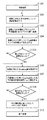
以下、本実施形態における補正プロファイル作成処理について、図2のフローチャートを用いて説明する。本実施形態における補正プロファイル作成アプリケーションは、以下の6つの処理を経て、色再現補正用プロファイルを作成する。すなわち、光源ランプ(以下、単にランプと称する)の温度測定、液晶パネルの温度測定、測定温度に基づくランプの分光分布算出、RGB反射率算出、プロジェクタの色再現情報推定、色再現補正用プロファイル作成、である。
● Creation profile creation process (outline)
Hereinafter, the correction profile creation processing in the present embodiment will be described with reference to the flowchart of FIG. The correction profile creation application in the present embodiment creates a color reproduction correction profile through the following six processes. That is, temperature measurement of a light source lamp (hereinafter simply referred to as a lamp), temperature measurement of a liquid crystal panel, calculation of a spectral distribution of the lamp based on the measurement temperature, calculation of RGB reflectance, estimation of projector color reproduction information, creation of a color reproduction correction profile .
まず、ステップS201において初期化動作を行い、次にステップS202において、後述するUIにより設定された条件を読み込む。そしてステップS203では、設定された条件から補正間隔情報を参照するとともに、タイマー118での計測を開始する。そしてステップS204において、タイマー118のカウント時間が設定間隔に達していればステップS205へ進み、それ以外であればタイマー118のカウントを継続する。
First, an initialization operation is performed in step S201, and then in step S202, conditions set by a UI described later are read. In step S203, the correction interval information is referred to from the set conditions, and measurement by the
ステップS205では、温度計109によってランプの温度を測定するとともに、温度計110〜112によって液晶パネル温度を測定する。このとき、測定した温度および測定が行われた旨を、CPU101へ送信する。
In step S205, the temperature of the lamp is measured by the
ステップS206では、温度計109にて測定した温度と、予め装置内の例えばHDD105に保持されている温度とランプの分光分布の関係情報から、ランプの分光分布情報を算出する。この分光分布情報の算出処理の詳細については後述する。
In step S206, the spectral distribution information of the lamp is calculated from the temperature measured by the
次にステップS207,S208,S209において、それぞれ温度計110,111,112にて測定した温度と、予め装置内の例えばHDD105に保持されている温度と各色パネル反射率の関係情報から、R,G,Bの液晶パネル反射率情報を算出する。この液晶パネル反射率情報の算出処理の詳細については後述する。
Next, in steps S207, S208, and S209, from the temperature measured by the
そしてステップS210において、ステップS206で算出したランプの分光分布情報と、ステップS207〜S209にて算出した液晶パネルの反射率情報、および等色関数とに基づき、RGB最大信号値の三刺激値を算出する。この三刺激値(XRYRZR等)の算出処理の詳細については後述する。 In step S210, the tristimulus value of the RGB maximum signal value is calculated based on the spectral distribution information of the lamp calculated in step S206, the reflectance information of the liquid crystal panel calculated in steps S207 to S209, and the color matching function. To do. Details of the processing for calculating the tristimulus values (X R Y R Z R, etc.) will be described later.
そしてステップS211において、ステップS210で得られたRGBの三刺激値に基づいて、以下の(1)式によりホワイト色(W)の三刺激値を算出する。 In step S211, based on the RGB tristimulus values obtained in step S210, the white (W) tristimulus values are calculated by the following equation (1).
XW=XR+XG+XB
YW=YR+YG+YB ・・・(1)
ZW=ZR+ZG+ZB
すなわち、RGBの合計としての最大信号値が、Wの三刺激値として得られる。
X W = X R + X G + X B
Y W = Y R + Y G + Y B (1)
Z W = Z R + Z G + Z B
That is, the maximum signal value as the sum of RGB is obtained as the W tristimulus value.
次にステップS212において、RGBおよびWの三刺激値に基づいてプロジェクタの色再現情報を算出するが、この詳細については後述する。 In step S212, projector color reproduction information is calculated based on the RGB and W tristimulus values, details of which will be described later.
そしてステップS213において、プロジェクタの色再現情報に基づいて補正用モニタプロファイル作成するが、この詳細については後述する。 In step S213, a correction monitor profile is created based on the color reproduction information of the projector. This will be described later in detail.
そしてステップS214において、補正プロファイル作成処理の終了に関する動作を行う。 In step S214, an operation related to the end of the correction profile creation process is performed.
●ユーザインタフェース(UI)
図3は、本実施形態における補正プロファイル作成アプリケーションUIのダイアログウィンドウである。同図において、301は補正を実行する時間間隔を設定するテキストボックスであり、ボックス内に数値(min)を入力する。302は維持すべき設定色温度を設定するテキストボックスであり、ボックス内に数値(K)を入力する。303は経時変化の許容ずれ量を設定するテキストボックスであり、ボックス内に数値(K)を入力する。304は補正プロファイルの適用タイミングについて、手動で適用させるか自動で適用させるかを選択するためのチェックボックスであり、手動で適用させる場合にはチェックを入れる。305は処理開始ボタンであり、このボタンを押下すると補正プロファイル作成処理を開始する。306は終了ボタンであり、このボタンを押下すると補正プロファイル作成アプリケーションを終了する。
● User interface (UI)
FIG. 3 is a dialog window of the correction profile creation application UI in the present embodiment. In the figure,
ここで、上記UIに基づく、本実施形態における補正プロファイル作成動作を、図4の状態図を用いて説明する。同図において、ステート401では、初期設定値を読み込むといった初期化動作を行う。ステート402では、図3に示すUIにおけるユーザ操作判断待ち状態となる。ここで、補正間隔テキストボックス301に変更が入力されるとステート403へ移行し、設定色温度設定テキストボックス302が変更されるとステート404へ移行する。また、経時変化の許容ずれ量を設定するテキストボックス303が変更されるとステート405へ移行し、自動手動選択チェックボックス305がチェックされるとステート406へ移行する。また、処理開始ボタン306が押下されるとステート407へ移行し、終了ボタン307が押下されるとステート408へ移行する。
Here, the correction profile creation operation in the present embodiment based on the UI will be described with reference to the state diagram of FIG. In the figure, in
●ランプの分光分布算出処理(S206)
以下、図2のステップS206における、ランプ温度からランプの分光分布を算出する処理について、図5のフローチャートを用いて説明する。
Lamp spectral distribution calculation process (S206)
Hereinafter, the process of calculating the spectral distribution of the lamp from the lamp temperature in step S206 of FIG. 2 will be described with reference to the flowchart of FIG.
まずステップS501において、ランプの温度と分光分布の関係情報の取得や、図3に示すダイアログウィンドウにて設定された情報の取得、およびメモリ領域の確保、等の初期化を行う。ここで、ランプの温度と分光分布の関係情報として、図6に示すLUTを取得するとする。 First, in step S501, initialization is performed such as acquisition of relationship information between lamp temperature and spectral distribution, acquisition of information set in the dialog window shown in FIG. 3, and securing of a memory area. Here, it is assumed that the LUT shown in FIG. 6 is acquired as the relationship information between the lamp temperature and the spectral distribution.
そしてステップS502において、温度計109にて測定したランプの温度を取得する。ステップS503では、ステップS502で取得したランプ温度と、図6に示すLUTに基づき、ランプの分光分布を算出する。このとき、波長の間隔は10nmとし、範囲は一般的な可視領域である380nm〜780nmとする。そしてステップS504で、終了に関する動作を行う。
In step S502, the lamp temperature measured by the
●パネル反射率算出処理(S207〜S209)
以下、図2のステップS207,S208,S209のそれぞれにおける、R,G,Bの各液晶パネルの反射率情報を算出する処理について、図7のフローチャートを用いて説明する。
Panel reflectance calculation process (S207 to S209)
Hereinafter, the process of calculating the reflectance information of each of the R, G, and B liquid crystal panels in each of steps S207, S208, and S209 of FIG. 2 will be described with reference to the flowchart of FIG.
まずステップS701において、温度とパネル反射率の関係情報の取得や、図3に示すダイアログウィンドウにて設定された情報の取得、およびメモリ領域の確保、等の初期化を行う。ここで、例えばR液晶パネルの温度と反射率の関係情報として、図8に示すようなLUTを取得するとする。 First, in step S701, initialization is performed such as acquisition of relationship information between temperature and panel reflectance, acquisition of information set in the dialog window shown in FIG. 3, and securing of a memory area. Here, for example, it is assumed that an LUT as shown in FIG. 8 is acquired as the relationship information between the temperature and reflectance of the R liquid crystal panel.
そしてステップS702において、各色用の温度計110〜112にて測定したRGBの各色パネルの温度を取得する。すなわち、ステップS707であればR色用の温度計110を用い、同様にステップS708であればG色用の温度計111を、ステップS709であればB色用の温度計112を用いて、それぞれのパネル温度を測定する。そしてさらに、階調を表す変数iに0を設定する。
In step S702, the temperatures of the RGB color panels measured by the
次にステップS703において、ステップS702にて取得した各色のパネル温度と、例えばR色であれば図8に示すような、温度と反射率の関係を表すLUTに基づき、RGBの各液晶パネルの反射率を算出する。そしてステップS704で、終了に関する動作を行う。 Next, in step S703, the reflection of each liquid crystal panel of RGB is based on the panel temperature of each color acquired in step S702 and the LUT indicating the relationship between temperature and reflectance as shown in FIG. Calculate the rate. In step S704, an operation related to termination is performed.
●RGB三刺激値算出処理(S210)
以下、図2のステップS210におけるRGBの三刺激値算出処理について、図9のフローチャートを用いて説明する。
RGB tristimulus value calculation process (S210)
Hereinafter, the RGB tristimulus value calculation processing in step S210 of FIG. 2 will be described using the flowchart of FIG.
まずステップS1101において、ステップS206にて算出したランプの分光分布、およびステップS207〜S209にて算出した各液晶パネルの反射率を取得する。 First, in step S1101, the spectral distribution of the lamp calculated in step S206 and the reflectance of each liquid crystal panel calculated in steps S207 to S209 are acquired.
そしてステップS1102において、等色関数を含む(2)式に基づいて、現在の色再現情報の白色情報からXYZを算出する。ここで、ランプの分光分布をE(λ)にて表すものとし、RGB各パネルの反射率をOR(λ),OG(λ),OB(λ)とする。また、Kは定数であり、K=683lm/Wである。 In step S1102, XYZ is calculated from the white color information of the current color reproduction information based on equation (2) including the color matching function. Here, the spectral distribution of the lamp is represented by E (λ), and the reflectance of each of the RGB panels is represented by O R (λ), O G (λ), and O B (λ). K is a constant, and K = 683 lm / W.

そしてステップS1103において、終了に関する処理を行う。 In step S1103, processing related to termination is performed.
これにより、RGB各単色における最大信号値が、三刺激値として得られる。 Thereby, the maximum signal value in each RGB single color is obtained as a tristimulus value.
●プロジェクタ色再現算出処理
以下、図2のステップS212におけるプロジェクタの色再現情報作成処理について、図10のフローチャートを用いて説明する。
Projector Color Reproduction Calculation Processing The projector color reproduction information creation processing in step S212 in FIG. 2 will be described below using the flowchart in FIG.
まずステップS1201において、ステップS210,S211で算出されたRGBおよびWのXYZ三刺激値の色再現情報を取得するとともに、メモリ領域の確保といった初期化を行う。 First, in step S1201, the color reproduction information of the RGB and W XYZ tristimulus values calculated in steps S210 and S211 is acquired, and initialization such as securing a memory area is performed.
そしてステップS1202において、RGB信号値とXYZ三刺激値から、以下の(3)式に基づいて色再現行列を作成する。ここで、xi,yi,zi,Si(i=R,G,B)はそれぞれ、RGBの色度座標および刺激和である。 In step S1202, a color reproduction matrix is created from the RGB signal values and the XYZ tristimulus values based on the following equation (3). Here, x i , y i , z i , and S i (i = R, G, B) are RGB chromaticity coordinates and stimulus sums, respectively.
(R)≡SR{xR(X)+yR(Y)+zR(Z)}
(G)≡SG{xG(X)+yG(Y)+zG(Z)} ・・・(3)
(B)≡SB{xB(X)+yB(Y)+zB(Z)}
また、ステップS211で算出された(W)の三刺激値については、以下の(4)式のように表せる。
(R) ≡S R {x R (X) + y R (Y) + z R (Z)}
(G) ≡S G {x G (X) + y G (Y) + z G (Z)} (3)
(B) ≡S B {x B (X) + y B (Y) + z B (Z)}
Further, the tristimulus value (W) calculated in step S211 can be expressed by the following equation (4).
(W)≡(R)+(G)+(B)
≡SW{xW(X)+yW(Y)+zW(Z)} ・・・(4)
ここで、(3)式を(4)式に代入すると、(5)式の関係が成り立つ。
(W) ≡ (R) + (G) + (B)
≡S W {x W (X) + y W (Y) + z W (Z)} (4)
Here, when the expression (3) is substituted into the expression (4), the relation of the expression (5) is established.
SRxR+SGxG+SBxB=SWxW
SRyR+SGyG+SByB=SWyW ・・・(5)
SRzR+SGzG+SBzB=SWzW
(5)式をSR,SG,SBについて解くと、以下の(6)式が得られる。
SR=SW(xWΔ11−yWΔ21+zWΔ31)/Δ
SG=SW(−xWΔ12+yWΔ22−zWΔ32)/Δ
SB=SW(xWΔ13−yWΔ23+zWΔ33)/Δ
・・・(6)
ただし、
S R x R + S G x G + S B x B = S W x W
S R y R + S G y G + S B y B = S W y W (5)
S R z R + S G z G + S B z B = S W z W
When the equation (5) is solved for S R , S G and S B , the following equation (6) is obtained.
S R = S W (x W Δ 11 −y W Δ 21 + z W Δ 31 ) / Δ
S G = S W (−x W Δ 12 + y W Δ 22 −z W Δ 32 ) / Δ
S B = S W (x W Δ 13 −y W Δ 23 + z W Δ 33 ) / Δ
... (6)
However,
このとき、ある色(F)の三刺激値をX,Y,Zとし、3原色表色系のそれをR,G,Bとすれば、等色式は以下の(7)式になる。 At this time, if the tristimulus values of a certain color (F) are X, Y, and Z, and those of the three primary color systems are R, G, and B, the color matching formula becomes the following formula (7).
(F)≡X(X)+Y(Y)+Z(Z)
≡R(R)+G(G)+B(B) ・・・(7)
これに、(5)式を代入することによって、等色が成り立つ条件として以下に示す(8)式が得られる。
(F) ≡X (X) + Y (Y) + Z (Z)
≡R (R) + G (G) + B (B) (7)
By substituting the equation (5) into this, the following equation (8) is obtained as a condition for achieving the same color.
SRxRR+SGxGG+SBxBB=X
SRyRR+SGyGG+SByBB=Y ・・・(8)
SRzRR+SGzGG+SBzBB=Z
この式をR,G,Bについて解き、(6)式を用いると、RGB信号値とXYZ値の関係は以下の(9)式として得られる。
S R x R R + S G x G G + S B x B B = X
S R y R R + S G y G G + S B y B B = Y (8)
S R z R R + S G z G G + S B z B B = Z
When this equation is solved for R, G, and B and equation (6) is used, the relationship between RGB signal values and XYZ values is obtained as the following equation (9).
以上のようにプロジェクタの色再現情報が得られると、次にステップS1203において、終了に関する処理を行う。 When the color reproduction information of the projector is obtained as described above, next, processing related to termination is performed in step S1203.
このように本実施形態においては、(2)式に示すようにランプの分光分布および液晶パネルの反射率、および等色関数に基づいて、RGBおよびWの三刺激値を算出し、該RGBWの三刺激値により、現在のプロジェクタ色再現情報を推測する。 Thus, in this embodiment, RGB and W tristimulus values are calculated based on the spectral distribution of the lamp, the reflectance of the liquid crystal panel, and the color matching function as shown in the equation (2). The current projector color reproduction information is estimated from the tristimulus values.
●補正プロファイル算出処理
以下、図2のステップS213における補正用モニタプロファイルの算出処理について、図11のフローチャートを用いて説明する。
Correction Profile Calculation Processing Hereinafter, the correction monitor profile calculation processing in step S213 in FIG. 2 will be described with reference to the flowchart in FIG.
まずステップS1301では、ステップS212にて生成したプロジェクタの色再現情報と、予め設定された補正後の目標色情報を取得するとともに、メモリ領域の確保や、3DLUTの各格子番号を表す変数iを0に設定する、等の初期化を行う。以下、3DLUTにおけるRGBの各値を、変数iを用いたRiGiBiにて表記する。 First, in step S1301, the projector color reproduction information generated in step S212 and target color information after correction set in advance are acquired, and a memory area is secured and a variable i representing each grid number of the 3DLUT is set to 0. , Etc. to initialize. Hereinafter, each RGB value in the 3DLUT is represented by RiGiBi using the variable i.
次にステップS1302では、変数iに対応するRGB値について、以下の(10)式を用いた非線形演算によって階調補正を行う。なお、ここで用いる階調特性をγとする。また、白色情報を示す最大信号値をRwGwBw、変換後の値をRi'Gi'Bi'とする。 In step S1302, tone correction is performed on the RGB value corresponding to the variable i by nonlinear calculation using the following equation (10). Note that the gradation characteristic used here is γ. Further, the maximum signal value indicating the white information is RwGwBw, and the converted value is Ri′Gi′Bi ′.
Ri'=(Ri/Rw)γ
Gi'=(Gi/Gw)γ ・・・(10)
Bi'=(Bi/Bw)γ
次にステップS1303において、ステップS1302で変換したRGB値について、ステップS212で算出したプロジェクタ色再現情報を示す変換行列((9)式)を用いて、以下の(11)式によりXYZ値へ変換する。このときの変換行列をM(m11,m12,…,m33)にてあらわすものとし、mijのiはi行、jはj列を表す。また、変換後の値をXiYiZiとする。
Ri ′ = (Ri / Rw) γ
Gi ′ = (Gi / Gw) γ (10)
Bi ′ = (Bi / Bw) γ
In step S1303, the RGB values converted in step S1302 are converted into XYZ values by the following equation (11) using the conversion matrix (equation (9)) indicating the projector color reproduction information calculated in step S212. . The conversion matrix at this time is represented by M (m11, m12,..., M33), i in mij represents i rows, and j represents j columns. The converted value is XiYiZi.
Xi = Ri'm11 + Gi'm12 + Bi'm13
Yi = Ri'm21 + Gi'm22 + Bi'm23 …(11)
Zi = Ri'm31 + Gi'm32 + Bi'm33
そしてステップS1304において、ステップS1303で算出したXiYiZiについて、以下の(12)式によりLab値に変換する。この変換後の値をLi*ai*bi*とし、このときの白色基準をXnYnZnとする。また、変数iに1を加算する。
Xi = Ri'm11 + Gi'm12 + Bi'm13
Yi = Ri'm21 + Gi'm22 + Bi'm23… (11)
Zi = Ri'm31 + Gi'm32 + Bi'm33
In step S1304, XiYiZi calculated in step S1303 is converted into an Lab value by the following equation (12). The value after this conversion is Li * ai * bi *, and the white reference at this time is XnYnZn. Also, 1 is added to the variable i.
この処理により、RGBとLabの対応関係を表す色情報LUTの一要素が得られる。 By this processing, one element of the color information LUT representing the correspondence between RGB and Lab is obtained.
そしてステップS1305において、変数iが所定値である、すなわち全ての色についてステップS1302〜S1304の演算が終了したのであればステップS1306へ進み、そうでなければステップS1302に戻って次の色についての処理を行う。 In step S1305, if the variable i is a predetermined value, that is, if the calculation in steps S1302 to S1304 has been completed for all colors, the process proceeds to step S1306; otherwise, the process returns to step S1302 and processing for the next color is performed. I do.
以上の処理により、現在のプロジェクタにおけるRGBとLabの対応関係を表す色情報LUTが得られる。 Through the above processing, color information LUT representing the correspondence between RGB and Lab in the current projector is obtained.
ステップS1306では、ステップS1301で得た補正後の目標色情報から、プロファイルを構成する色情報として、変数jに対応するLabtagを取得する。なおこのとき、tagの番号を表すjは0に設定されている。 In step S1306, Labtag corresponding to the variable j is acquired as color information constituting the profile from the corrected target color information obtained in step S1301. At this time, j representing the tag number is set to 0.
そしてステップS1307では、以上のように作成された色情報LUTを用いた四面体補間演算により、Labtag→RGB変換を施す。なお、色情報LUTは、Lab色空間での格子点の色座標データと、該格子点が再現するRGB色空間の座標値との対応を記したデータ構造からなる。また四面体補間とは、隣接する8つの格子点で囲まれる6面体領域を、6つに分割された四面体領域毎に補間する演算である。演算後のRGB値をRjGjBjとする。また、変数jに1を加算する。 In step S1307, Labtag → RGB conversion is performed by tetrahedral interpolation using the color information LUT created as described above. The color information LUT has a data structure that describes the correspondence between the color coordinate data of the grid point in the Lab color space and the coordinate value of the RGB color space reproduced by the grid point. Further, the tetrahedral interpolation is an operation for interpolating a hexahedral area surrounded by eight adjacent lattice points for every tetrahedral area divided into six. The RGB value after the calculation is RjGjBj. Also, 1 is added to the variable j.
そしてステップS1308において、変数jが所定値である、すなわち全ての色についてステップS1306〜S1307の演算が終了したのであればステップS1309へ進み、そうでなければステップS1306に戻って次の色についての処理を行う。 In step S1308, if the variable j is a predetermined value, that is, if the calculation in steps S1306 to S1307 has been completed for all colors, the process proceeds to step S1309. If not, the process returns to step S1306 to process the next color. I do.
ステップS1309では、求められたRjGjBjを補正用LUTとして、メモリ102へ書き込む。そしてステップS1310において、終了に関する動作を行う。
In step S1309, the obtained RjGjBj is written in the
以上のように本実施形態の補正プロファイルとしては、RGBが各単色レベルで変動した場合や、またホワイトと他の色の変動傾向が異なっていた場合であっても、高精度な補正プロファイルを作成することが可能である。 As described above, as the correction profile of the present embodiment, a highly accurate correction profile is created even when RGB fluctuates at each single color level or when the fluctuation tendency of white and other colors is different. Is possible.
●本実施形態の効果
以上説明したように本実施形態によれば、ランプおよび液晶パネルの温度を測定し、得られた温度に基づいて、ランプの分光分布、およびパネルの反射率を算出し、プロジェクタの現在の状態に応じたRGBWの三刺激値XYZを求める。そして、このRGBWのXYZ値からプロジェクタ色再現を推定し、適切な補正プロファイル(LUT)を作成する。これにより、プロジェクタの経時変化、すなわちランプの発熱による色再現の変動を排除するような補正プロファイルをリアルタイムかつ簡易に作成することができ、プロジェクタ色再現を一定に保つことが可能となる。
As described above, according to this embodiment, the temperature of the lamp and the liquid crystal panel is measured, and based on the obtained temperature, the spectral distribution of the lamp and the reflectance of the panel are calculated. RGBW tristimulus values XYZ corresponding to the current state of the projector are obtained. Then, projector color reproduction is estimated from the RGBW XYZ values, and an appropriate correction profile (LUT) is created. As a result, a correction profile that eliminates changes in the projector over time, that is, fluctuations in color reproduction due to heat generation of the lamp, can be easily created in real time, and projector color reproduction can be kept constant.
<第2実施形態>
以下、本発明に係る第2実施形態について説明する。第2実施形態における画像処理装置の構成は、上述した第1実施形態で図1に示した構成と同様であるため、ここでは説明を省略する。
Second Embodiment
Hereinafter, a second embodiment according to the present invention will be described. Since the configuration of the image processing apparatus in the second embodiment is the same as that shown in FIG. 1 in the first embodiment described above, description thereof is omitted here.
第2実施形態においても、上述した第1実施形態と同様に、ランプの分光分布およびパネルの反射率によってRGBWの三刺激値XYZを算出し、これによって推定されるプロジェクタ色再現に基づいて適切な補正プロファイルを作成する。ただし第2実施形態では、上述した第1実施形態で図2のフローチャートに示した補正プロファイル作成処理において、ステップS207〜S211でのRGBWの三刺激値算出時に、RGB等色グレイの三刺激値も合わせて算出する。そして該算出結果を用いて、ステップS212における色再現情報の作成を行なうことによって、グレイ近傍の補正精度を向上させることを特徴とする。 Also in the second embodiment, as in the first embodiment described above, RGBW tristimulus values XYZ are calculated from the spectral distribution of the lamp and the reflectance of the panel, and appropriate values are obtained based on the projector color reproduction estimated thereby. Create a correction profile. However, in the second embodiment, in the correction profile creation process shown in the flowchart of FIG. 2 in the first embodiment described above, when the RGBW tristimulus values are calculated in steps S207 to S211, the RGB trichromatic gray tristimulus values are also calculated. Calculate together. Then, using the calculation result, the color reproduction information is created in step S212, thereby improving the correction accuracy near gray.
以下では、特に第1実施形態と異なる点について、説明する。 Below, especially a different point from 1st Embodiment is demonstrated.
●補正プロファイル作成処理
第2実施形態における補正プロファイル作成処理の概要について、図12のフローチャートを用いて説明する。第2実施形態における補正プロファイル作成アプリケーションも、上述した第1実施形態と同様の6つの処理を経て、色再現補正用プロファイルを作成する。すなわち、光源ランプの温度測定、液晶パネルの温度測定、測定温度に基づくランプの分光分布算出、RGB反射率算出、プロジェクタの色再現情報推定、色再現補正用プロファイル作成、の6つである。
Correction Profile Creation Process An outline of the correction profile creation process in the second embodiment will be described using the flowchart of FIG. The correction profile creation application in the second embodiment also creates a color reproduction correction profile through the same six processes as in the first embodiment described above. That is, there are six types of measurement: light source lamp temperature measurement, liquid crystal panel temperature measurement, lamp spectral distribution calculation based on the measurement temperature, RGB reflectance calculation, projector color reproduction information estimation, and color reproduction correction profile creation.
まず、ステップS1401において初期化動作を行い、次にステップS1402において、第1実施形態で図3に示したUIにより設定された条件を読み込む。そしてステップS1403では、設定された条件から補正間隔情報を参照するとともに、タイマー118での計測を開始する。そしてステップS1404において、タイマー118のカウント時間が設定間隔に達していればステップS1405へ進み、それ以外であればタイマー118のカウントを継続する。
First, an initialization operation is performed in step S1401, and then in step S1402, conditions set by the UI shown in FIG. 3 in the first embodiment are read. In step S1403, the correction interval information is referred to from the set condition, and measurement by the
ステップS1405では、温度計109によってランプの温度を測定するとともに、温度計110〜112によって液晶パネル温度を測定する。このとき、測定した温度および測定が行われた旨を、CPU101へ送信する。
In step S1405, the temperature of the lamp is measured by the
ステップS1406では、温度計109にて測定した温度と、予め装置内の例えばHDD105に保持されている温度とランプの分光分布の関係情報から、ランプの分光分布情報を算出する。この分光分布情報の算出処理の詳細については後述する。
In step S1406, the spectral distribution information of the lamp is calculated from the temperature measured by the
次にステップS1407,S1408,S1409において、それぞれ温度計110,111,112にて測定した温度と、予め装置内に保持されている、温度とR,G,B液晶パネル反射率の関係情報から、R,G,Bの液晶パネル反射率情報を算出する。この液晶パネル反射率情報の算出処理の詳細については後述する。
Next, in steps S1407, S1408, and S1409, from the temperature measured by the
そしてステップS1410において、ステップS1406で算出したランプの分光分布情報と、ステップS1407〜S1409にて算出した液晶パネルの反射率情報、および等色関数とに基づき、RGB信号値の三刺激値を算出する。この三刺激値の算出処理については、上述した第1実施形態と同様であるため、説明を省略する。 In step S1410, tristimulus values of RGB signal values are calculated based on the spectral distribution information of the lamp calculated in step S1406, the reflectance information of the liquid crystal panel calculated in steps S1407 to S1409, and the color matching function. . Since this tristimulus value calculation process is the same as that of the first embodiment described above, the description thereof is omitted.
そしてステップS1411において、以下の(13)式によりRGB等色グレイの三刺激値を算出する。ここで、階調数をjで示し、階調jにおけるRGB等色グレイの三刺激値XYZを、XGray j YGray j ZGray jとする。 In step S1411, tristimulus values of RGB equal gray are calculated by the following equation (13). Here, the number of gradations is indicated by j, and the RGB trichromatic gray tristimulus values XYZ at the gradation j are assumed to be X Gray j Y Gray j Z Gray j .
XGray j=XRj+XGj+XBj
YGray j=YRj+YGj+YBj (13)
ZGray j=ZRj+ZGj+ZBj
そして、ステップS1412において、上述した第1実施形態と同様にプロジェクタの色再現情報を算出し、ステップS1413で補正用モニタプロファイル作成する。なお、この補正用モニタプロファイルの算出処理の詳細については後述する。
X Gray j = X Rj + X Gj + X Bj
Y Gray j = Y Rj + Y Gj + Y Bj (13)
Z Gray j = Z Rj + Z Gj + Z Bj
In step S1412, the projector color reproduction information is calculated in the same manner as in the first embodiment described above. In step S1413, a correction monitor profile is created. Details of the correction monitor profile calculation process will be described later.
そして、ステップS214で終了に関する動作を行う。 In step S214, an operation related to termination is performed.
●ランプの分光分布算出処理(S1406)
以下、図12のステップS1406における、ランプ温度からランプの分光分布を算出する処理について、図13のフローチャートを用いて説明する。
Lamp spectral distribution calculation process (S1406)
Hereinafter, the process of calculating the spectral distribution of the lamp from the lamp temperature in step S1406 of FIG. 12 will be described with reference to the flowchart of FIG.
まずステップS1501において、ランプの温度と分光分布の関係情報の取得や、図3に示すダイアログウィンドウにて設定された情報の取得、およびメモリ領域の確保、等の初期化を行う。ここで、ランプの温度と分光分布の関係情報として、図6に示すLUTを取得するとする。 First, in step S1501, initialization is performed such as acquisition of relationship information between lamp temperature and spectral distribution, acquisition of information set in the dialog window shown in FIG. 3, and securing of a memory area. Here, it is assumed that the LUT shown in FIG. 6 is acquired as the relationship information between the lamp temperature and the spectral distribution.
そしてステップS1502において、温度計109にて測定したランプの温度を取得するとともに、階調を表す変数iに0を設定する。
In step S1502, the temperature of the lamp measured by the
ステップS1503では、ステップS1502で取得したランプ温度と、図6に示すLUTに基づき、変数iに対応したランプの分光分布を算出する。そしてさらに、変数iに1を加算する。 In step S1503, the spectral distribution of the lamp corresponding to the variable i is calculated based on the lamp temperature acquired in step S1502 and the LUT shown in FIG. Further, 1 is added to the variable i.
そしてステップS1504において、変数iが所定の数に達した、すなわち全ての階調について分光分布の算出が終了したのであればステップS1505へ進み、そうでなければステップS1503へ戻る。 In step S1504, if the variable i has reached a predetermined number, that is, if the calculation of the spectral distribution has been completed for all the gradations, the process proceeds to step S1505; otherwise, the process returns to step S1503.
そしてステップS1505で、終了に関する動作を行う。 In step S1505, an operation related to termination is performed.
●パネル反射率算出処理(S1407〜S1409)
以下、図12のステップS1407,S1408,S1409のそれぞれにおける、R,G,Bの各液晶パネルの反射率情報を算出する処理について、図14のフローチャートを用いて説明する。
Panel reflectance calculation process (S1407 to S1409)
Hereinafter, processing for calculating reflectance information of each of the R, G, and B liquid crystal panels in steps S1407, S1408, and S1409 of FIG. 12 will be described with reference to the flowchart of FIG.
まずステップS1601において、温度とパネル反射率の関係情報の取得や、図3に示すダイアログウィンドウにて設定された情報の取得、およびメモリ領域の確保、等の初期化を行う。ここで、例えばR液晶パネルの温度とパネル反射率の関係情報として、図8に示すようなLUTを取得するとする。 First, in step S1601, initialization is performed such as acquisition of relationship information between temperature and panel reflectance, acquisition of information set in the dialog window shown in FIG. 3, and securing of a memory area. Here, for example, it is assumed that an LUT as shown in FIG. 8 is acquired as the relationship information between the temperature of the R liquid crystal panel and the panel reflectance.
そしてステップS1602において、各色用の温度計110〜112にて測定した、RGBの各液晶パネルの温度を取得する。すなわち、ステップS1407であればR色用の温度計110を用い、同様にステップS1408であればG色用の温度計111を、ステップS1409であればB色用の温度計112を用いて、それぞれのパネル温度を測定する。そしてさらに、階調を表す変数iに0を設定する。
In step S1602, the temperatures of the RGB liquid crystal panels measured by the
次にステップS1603において、ステップS1602にて取得した各色のパネル温度と、例えばR色であれば図8に示すような、温度とパネル反射率の関係を表すLUTに基づき、変数iに対応した、RGBの各液晶パネルの反射率を算出する。そしてさらに、変数iに1を加算する。 Next, in step S1603, based on the panel temperature of each color acquired in step S1602 and the LUT representing the relationship between the temperature and the panel reflectance as shown in FIG. The reflectance of each RGB liquid crystal panel is calculated. Further, 1 is added to the variable i.
そしてステップS1604において、変数iが所定の数に達した、すなわち全ての階調について各色パネルの反射率の算出が終了したのであればステップS1605へ進み、そうでなければステップS1603へ戻る。 In step S1604, if the variable i has reached a predetermined number, that is, if the calculation of the reflectance of each color panel has been completed for all gradations, the process proceeds to step S1605; otherwise, the process returns to step S1603.
そしてステップS1605で、終了に関する動作を行う。 In step S1605, an operation related to termination is performed.
●補正プロファイル算出処理
以下、図12のステップS1413における補正用モニタプロファイルの算出処理について、図15のフローチャートを用いて説明する。
Correction Profile Calculation Processing Hereinafter, the correction monitor profile calculation processing in step S1413 in FIG. 12 will be described with reference to the flowchart in FIG.
まずステップS1901では、ステップS1412にて生成したモニタ色再現情報、補正後の目標色情報を取得するとともに、メモリ領域の確保や、3DLUTの各格子番号を表す変数iを0に設定する、等の初期化を行う。以下、3DLUTにおけるRGBの各値を、変数iを用いたRiGiBiにて表記する。 First, in step S1901, monitor color reproduction information and corrected target color information generated in step S1412 are acquired, a memory area is secured, and a variable i representing each grid number of the 3DLUT is set to 0. Perform initialization. Hereinafter, each RGB value in the 3DLUT is represented by RiGiBi using the variable i.
次にステップS1902では、変数iに対応するRGB値について、R、G、Bが等量であるか否か、すなわち等色グレイであるか否かを判定する。ここでR、G、Bが等量であればステップS1905へ進み、該RGB値のXYZ変換値としてステップS1411で算出した対応するグレイのXYZ値を充てて、ステップS1906へ進む。R、G、Bが等量でなければステップS1903へ進む。 Next, in step S1902, it is determined whether or not R, G, and B are equal amounts, that is, whether they are equal color gray, for the RGB value corresponding to the variable i. If R, G, and B are equal, the process proceeds to step S1905, and the corresponding XYZ value calculated in step S1411 is used as the XYZ conversion value of the RGB value, and the process proceeds to step S1906. If R, G, and B are not equal, the process proceeds to step S1903.
ステップS1903では、変数iに対応するRGB値について、ステップS1407〜ステップS1409にて算出したRGBの各階調特性情報を用いた1DLUTにより、階調補正を行う。また、変換後の値をRi'Gi'Bi'とする。 In step S1903, gradation correction is performed on the RGB value corresponding to the variable i by 1DLUT using each gradation characteristic information of RGB calculated in steps S1407 to S1409. The converted value is Ri′Gi′Bi ′.
次にステップS1904において、ステップS1903で変換したRGB値について、ステップS1412で算出したプロジェクタ色再現情報を示す変換行列((9)式)を用いて、上述した第1実施形態で示した(11)式によりXYZ値へ変換する。また、変換後の値をXiYiZiとする。 Next, in step S1904, the RGB values converted in step S1903 are shown in the above-described first embodiment using the conversion matrix (formula (9)) indicating the projector color reproduction information calculated in step S1412 (11). Convert to XYZ value by formula. The converted value is XiYiZi.
そしてステップS1906において、ステップS1904で算出したXiYiZiについて、上述した第1実施形態で示した(12)式によりLab値に変換する。この変換後の値をLi*ai*bi*とし、このときの白色異基準をXnYnZnとする。また、変数iに1を加算する。 In step S1906, XiYiZi calculated in step S1904 is converted into a Lab value by the expression (12) shown in the first embodiment. The value after this conversion is Li * ai * bi *, and the white reference at this time is XnYnZn. Also, 1 is added to the variable i.
この処理により、RGBとLabの対応関係を表す色情報LUTの一要素が得られる。 そしてステップS1907において、変数iが所定値である、すなわち全ての色についてステップS1902〜S1906の演算が終了したのであればステップS1908へ進み、そうでなければステップS1902に戻って次の色についての処理を行う。 By this processing, one element of the color information LUT representing the correspondence between RGB and Lab is obtained. In step S1907, if the variable i is a predetermined value, that is, if the calculation in steps S1902 to S1906 has been completed for all colors, the process proceeds to step S1908; otherwise, the process returns to step S1902 and processing for the next color is performed. I do.
以上の処理により、現在のプロジェクタにおけるRGBとLabの対応関係を表す色情報LUTが得られる。 Through the above processing, color information LUT representing the correspondence between RGB and Lab in the current projector is obtained.
ステップS1908では、ステップS1901で得た補正後の目標色情報から、プロファイルを構成する色情報として、変数jに対応するLabtagを取得する。なおこのとき、tagの番号を表すjは0に設定されている。 In step S1908, Labtag corresponding to the variable j is acquired as color information constituting the profile from the corrected target color information obtained in step S1901. At this time, j representing the tag number is set to 0.
そしてステップS1909では第1実施形態と同様に、以上のように作成された色情報LUTを用いた四面体補間演算により、Labtag→RGB変換を施す。また、変数jに1を加算する。 In step S1909, as in the first embodiment, Labtag → RGB conversion is performed by tetrahedral interpolation using the color information LUT created as described above. Also, 1 is added to the variable j.
そしてステップS1909では、色情報LUTを用いた四面体補間演算により、Labtag→RGB変換を施す。また、演算後のRGB値をRjGjBjとする。また、変数jに1を加算する。 In step S1909, Labtag → RGB conversion is performed by tetrahedral interpolation using the color information LUT. Further, the RGB value after the calculation is RjGjBj. Also, 1 is added to the variable j.
そしてステップS1910において、変数jが所定値である、すなわち全ての色についてステップS1908〜S1909の演算が終了したのであればステップS1910へ進み、そうでなければステップS1908に戻って次の色についての処理を行う。 In step S1910, if the variable j is a predetermined value, that is, if the calculations in steps S1908 to S1909 have been completed for all colors, the process proceeds to step S1910. Otherwise, the process returns to step S1908 and the process for the next color is performed. I do.
ステップS1911では、求められたRjGjBjを補正用LUTとして、メモリ102へ書き込む。そしてステップS1912において、終了に関する動作を行う。
In step S1911, the obtained RjGjBj is written in the
●第2実施形態の効果
以上説明したように第2実施形態によれば、補正プロファイルの作成時にグレイの各階調をより高精度な補正値に置き換えることにより、上述した第1実施形態に対してさらに、中間調においてより高精度な色補正を行うことが可能となる。
Advantages of the Second Embodiment As described above, according to the second embodiment, the gray levels are replaced with higher-accuracy correction values at the time of creating a correction profile, so that the first embodiment described above can be obtained. Furthermore, it is possible to perform color correction with higher accuracy in the halftone.
<変形例>
上述した各実施形態においては、補正対象となる変動量を色温度にて指定する例を示したが、これを色差や色度にて指定することも可能である。
<Modification>
In each of the above-described embodiments, an example in which the variation amount to be corrected is designated by the color temperature has been shown, but this can also be designated by the color difference or chromaticity.
また、上述した各実施形態においては、液晶パネルの反射率を算出する例を示したが、これを透過率によって代替することも可能である。 Moreover, in each embodiment mentioned above, although the example which calculates the reflectance of a liquid crystal panel was shown, it is also possible to substitute this with the transmittance | permeability.
また、上述した各実施形態においては、温度と分光分布の関係を記した情報からランプの分光分布を算出する例を示したが、各波長の温度と分光分布の関係を表す数式から算出することも可能である。同様に、温度とパネル反射率の関係を記した情報から液晶パネルの反射率を算出する例を示したが、各波長の温度と反射率の関係を表す数式から算出する方法を用いることも可能である。 Further, in each of the above-described embodiments, the example in which the spectral distribution of the lamp is calculated from the information describing the relationship between the temperature and the spectral distribution is shown. Is also possible. Similarly, the example of calculating the reflectance of the liquid crystal panel from the information describing the relationship between the temperature and the panel reflectance has been shown, but it is also possible to use a method of calculating from a mathematical expression representing the relationship between the temperature and the reflectance of each wavelength. It is.
また、上述した第1実施形態においては、補正プロファイル作成時の階調補正処理としてγ演算を行う例を示したが、これを1DLUTによる補間演算で代替することも可能である。また、対数演算等の様々な演算を組み合わせることも可能である。 In the first embodiment described above, an example in which the γ operation is performed as the gradation correction processing at the time of creating the correction profile has been described. However, this can be replaced by an interpolation operation using a 1DLUT. It is also possible to combine various operations such as logarithmic operations.
また、上述した各実施形態においては、プロジェクタの色再現を算出する際(S212,S1412)の色変換方法として、色変換行列を用いる例を示したが、演算時間の短縮のために、LUTを用いた近似演算による色変換を行うことも可能である。また、D.L.S.法や直交化法、準ニュートン法等の最適化手法を適用して、実測値と高精度に近似する多項式による色変換行列作成を行うことも可能である。さらに、色変換行列に白色あるいは特定の色を保存する拘束条件を付加することも可能である。 In each of the above-described embodiments, an example of using a color conversion matrix as a color conversion method when calculating the color reproduction of the projector (S212, S1412) has been described. However, in order to reduce the calculation time, an LUT is used. It is also possible to perform color conversion by the approximate calculation used. D. L. S. It is also possible to create a color conversion matrix by using polynomials that approximate measured values and high accuracy by applying an optimization method such as a method, an orthogonalization method, or a quasi-Newton method. Furthermore, it is possible to add a constraint condition for storing white or a specific color to the color conversion matrix.
<他の実施形態>
以上、実施形態例を詳述したが、本発明は例えば、システム、装置、方法、プログラム若しくは記憶媒体(記録媒体)等としての実施態様をとることが可能である。具体的には、複数の機器(例えば、ホストコンピュータ、インタフェース機器、撮像装置、webアプリケーション等)から構成されるシステムに適用しても良いし、また、一つの機器からなる装置に適用しても良い。
<Other embodiments>
Although the embodiment has been described in detail above, the present invention can take an embodiment as a system, apparatus, method, program, storage medium (recording medium), or the like. Specifically, the present invention may be applied to a system composed of a plurality of devices (for example, a host computer, an interface device, an imaging device, a web application, etc.), or may be applied to a device composed of a single device. good.
尚本発明は、前述した実施形態の機能を実現するソフトウェアのプログラムを、システムあるいは装置に直接あるいは遠隔から供給し、そのシステムあるいは装置のコンピュータが該供給されたプログラムコードを読み出して実行することによっても達成される。なお、この場合のプログラムとは、実施形態において図に示したフローチャートに対応したプログラムである。 In the present invention, a software program for realizing the functions of the above-described embodiments is supplied directly or remotely to a system or apparatus, and the computer of the system or apparatus reads and executes the supplied program code. Is also achieved. The program in this case is a program corresponding to the flowchart shown in the drawing in the embodiment.
従って、本発明の機能処理をコンピュータで実現するために、該コンピュータにインストールされるプログラムコード自体も本発明を実現するものである。つまり、本発明は、本発明の機能処理を実現するためのコンピュータプログラム自体も含まれる。 Accordingly, since the functions of the present invention are implemented by computer, the program code installed in the computer also implements the present invention. In other words, the present invention includes a computer program itself for realizing the functional processing of the present invention.
その場合、プログラムの機能を有していれば、オブジェクトコード、インタプリタにより実行されるプログラム、OSに供給するスクリプトデータ等の形態であっても良い。 In this case, as long as it has a program function, it may be in the form of object code, a program executed by an interpreter, script data supplied to the OS, or the like.
プログラムを供給するための記録媒体としては、以下に示す媒体がある。例えば、フロッピー(登録商標)ディスク、ハードディスク、光ディスク、光磁気ディスク、MO、CD-ROM、CD-R、CD-RW、磁気テープ、不揮発性のメモリカード、ROM、DVD(DVD-ROM,DVD-R)などである。 Recording media for supplying the program include the following media. For example, floppy disk, hard disk, optical disk, magneto-optical disk, MO, CD-ROM, CD-R, CD-RW, magnetic tape, nonvolatile memory card, ROM, DVD (DVD-ROM, DVD- R).
プログラムの供給方法としては、以下に示す方法も可能である。すなわち、クライアントコンピュータのブラウザからインターネットのホームページに接続し、そこから本発明のコンピュータプログラムそのもの(又は圧縮され自動インストール機能を含むファイル)をハードディスク等の記録媒体にダウンロードする。また、本発明のプログラムを構成するプログラムコードを複数のファイルに分割し、それぞれのファイルを異なるホームページからダウンロードすることによっても実現可能である。つまり、本発明の機能処理をコンピュータで実現するためのプログラムファイルを複数のユーザに対してダウンロードさせるWWWサーバも、本発明に含まれるものである。 As a program supply method, the following method is also possible. That is, the browser of the client computer is connected to a homepage on the Internet, and the computer program itself (or a compressed file including an automatic installation function) of the present invention is downloaded to a recording medium such as a hard disk. It can also be realized by dividing the program code constituting the program of the present invention into a plurality of files and downloading each file from a different homepage. That is, a WWW server that allows a plurality of users to download a program file for realizing the functional processing of the present invention on a computer is also included in the present invention.
また、本発明のプログラムを暗号化してCD-ROM等の記憶媒体に格納してユーザに配布し、所定の条件をクリアしたユーザに対し、インターネットを介してホームページから暗号化を解く鍵情報をダウンロードさせることも可能である。すなわち該ユーザは、その鍵情報を使用することによって暗号化されたプログラムを実行し、コンピュータにインストールさせることができる。 In addition, the program of the present invention is encrypted, stored in a storage medium such as a CD-ROM, distributed to users, and key information for decryption is downloaded from a homepage via the Internet to users who have cleared predetermined conditions. It is also possible to make it. That is, the user can execute the encrypted program by using the key information and install it on the computer.
また、コンピュータが、読み出したプログラムを実行することによって、前述した実施形態の機能が実現される。さらに、そのプログラムの指示に基づき、コンピュータ上で稼動しているOSなどが、実際の処理の一部または全部を行い、その処理によっても前述した実施形態の機能が実現され得る。 Further, the functions of the above-described embodiments are realized by the computer executing the read program. Furthermore, based on the instructions of the program, an OS or the like running on the computer performs part or all of the actual processing, and the functions of the above-described embodiments can also be realized by the processing.
さらに、記録媒体から読み出されたプログラムが、コンピュータに挿入された機能拡張ボードやコンピュータに接続された機能拡張ユニットに備わるメモリに書き込まれた後、実行されることによっても、前述した実施形態の機能が実現される。すなわち、該プログラムの指示に基づき、その機能拡張ボードや機能拡張ユニットに備わるCPUなどが実際の処理の一部または全部を行うことが可能である。 Further, the program read from the recording medium is written in a memory provided in a function expansion board inserted into the computer or a function expansion unit connected to the computer, and then executed, so that the program of the above-described embodiment can be obtained. Function is realized. That is, based on the instructions of the program, the CPU provided in the function expansion board or function expansion unit can perform part or all of the actual processing.
Claims (4)
前記光源ランプの温度を測定するランプ温度測定手段と、
前記液晶パネルそれぞれの温度を測定するパネル温度測定手段と、
前記測定した前記光源ランプの温度、および、前記光源ランプの温度と分光分布の関係を示すテーブルを参照して、該光源ランプの分光分布を取得する第一の取得手段と、
前記測定した前記液晶パネルそれぞれの温度、および、前記液晶パネルの温度と反射率の関係を示すテーブルを参照して、該液晶パネルそれぞれの反射率または透過率を取得する第二の取得手段と、
前記分光分布、および、前記液晶パネルそれぞれの反射率または透過率に基づいて、前記液晶プロジェクタ装置における色再現情報を算出する算出手段と、
前記算出された色再現情報に基づいて、前記カラー画像を表すRGB値を補正する補正用プロファイルを作成するプロファイル作成手段とを有することを特徴とする液晶プロジェクタ装置。 The light source lamp R light, G light, Divide the B light, the R light, G light, B light, and enlarged and projected on a screen via the liquid crystal panel corresponding to each projected color images on the screen A liquid crystal projector device,
Lamp temperature measuring means for measuring the temperature of the light source lamp;
Panel temperature measuring means for measuring the temperature of each of the liquid crystal panels;
A first acquisition means for acquiring a spectral distribution of the light source lamp with reference to a table showing a relationship between the measured temperature of the light source lamp and the temperature of the light source lamp and a spectral distribution;
The measured liquid crystal panel each of temperature, and, by referring to the table showing the relationship between the temperature and the reflectivity of the liquid crystal panel, a second acquiring means for acquiring a reflectance or transmittance of each said liquid crystal panel,
The spectral distribution and the calculation means based on the reflectance or transmittance of each of the liquid crystal panel, and calculates the color reproduction information in the liquid crystal projector device,
A liquid crystal projector apparatus comprising: a profile creating unit that creates a correction profile for correcting an RGB value representing the color image based on the calculated color reproduction information.
前記光源ランプの温度を測定するステップと、
前記液晶パネルそれぞれの温度を測定するステップと、
前記測定した前記光源ランプの温度、および、前記光源ランプの温度と分光分布の関係を示すテーブルを参照して、該光源ランプの分光分布を取得するステップと、
前記測定した前記液晶パネルそれぞれの温度、および、前記液晶パネルの温度と反射率の関係を示すテーブルを参照して、該液晶パネルそれぞれの反射率または透過率を取得するステップと、
前記分光分布、および、前記液晶パネルそれぞれの反射率または透過率に基づいて、前記液晶プロジェクタ装置における色再現情報を算出するステップと、
前記算出された色再現情報に基づいて、前記カラー画像を表すRGB値を補正する補正用プロファイルを作成するステップとを有することを特徴とする液晶プロジェクタ装置の制御方法。 The light source lamp R light, G light, Divide the B light, the R light, G light, B light, and enlarged and projected on a screen via the liquid crystal panel corresponding to each projected color images on the screen A liquid crystal projector device control method comprising:
Measuring the temperature of the light source lamp;
Measuring the temperature of each of the liquid crystal panels;
Obtaining the spectral distribution of the light source lamp with reference to the measured temperature of the light source lamp and a table showing the relationship between the temperature of the light source lamp and the spectral distribution;
The measured liquid crystal panel each of temperature, and a step of referring to a table showing the relationship between the temperature and the reflectivity of the liquid crystal panel to obtain a reflectance or transmittance of each said liquid crystal panel,
A step wherein the spectral distribution, and, based on the reflectance or transmittance of each of the liquid crystal panel, and calculates the color reproduction information in the liquid crystal projector device,
And a step of creating a correction profile for correcting RGB values representing the color image based on the calculated color reproduction information.
Priority Applications (1)
| Application Number | Priority Date | Filing Date | Title |
|---|---|---|---|
| JP2006331138A JP4900940B2 (en) | 2006-12-07 | 2006-12-07 | Liquid crystal projector device and control method thereof |
Applications Claiming Priority (1)
| Application Number | Priority Date | Filing Date | Title |
|---|---|---|---|
| JP2006331138A JP4900940B2 (en) | 2006-12-07 | 2006-12-07 | Liquid crystal projector device and control method thereof |
Publications (3)
| Publication Number | Publication Date |
|---|---|
| JP2008145608A JP2008145608A (en) | 2008-06-26 |
| JP2008145608A5 JP2008145608A5 (en) | 2010-01-28 |
| JP4900940B2 true JP4900940B2 (en) | 2012-03-21 |
Family
ID=39605877
Family Applications (1)
| Application Number | Title | Priority Date | Filing Date |
|---|---|---|---|
| JP2006331138A Expired - Fee Related JP4900940B2 (en) | 2006-12-07 | 2006-12-07 | Liquid crystal projector device and control method thereof |
Country Status (1)
| Country | Link |
|---|---|
| JP (1) | JP4900940B2 (en) |
Families Citing this family (4)
| Publication number | Priority date | Publication date | Assignee | Title |
|---|---|---|---|---|
| WO2013108646A1 (en) * | 2012-01-16 | 2013-07-25 | シャープ株式会社 | Display device |
| JP6212713B2 (en) * | 2013-01-17 | 2017-10-18 | パナソニックIpマネジメント株式会社 | Image projection apparatus and image projection method |
| JP2017003949A (en) * | 2015-06-16 | 2017-01-05 | 大日本印刷株式会社 | Liquid crystal display and color correction program |
| JP6789845B2 (en) | 2017-02-22 | 2020-11-25 | 三菱電機株式会社 | White balance adjustment method, method of manufacturing a display device with white balance adjustment, white balance adjustment device and display device |
Family Cites Families (4)
| Publication number | Priority date | Publication date | Assignee | Title |
|---|---|---|---|---|
| JP2004101722A (en) * | 2002-09-06 | 2004-04-02 | Matsushita Electric Ind Co Ltd | Illumination optical device, projection type display device, and back projection type display device using same |
| JP4417784B2 (en) * | 2003-09-05 | 2010-02-17 | シャープ株式会社 | Light emitting device and display device |
| JP4508754B2 (en) * | 2004-07-14 | 2010-07-21 | 三菱電機株式会社 | Image display device and image display method |
| JP4805026B2 (en) * | 2006-05-29 | 2011-11-02 | シャープ株式会社 | LIGHT EMITTING DEVICE, DISPLAY DEVICE, AND LIGHT EMITTING DEVICE CONTROL METHOD |
-
2006
- 2006-12-07 JP JP2006331138A patent/JP4900940B2/en not_active Expired - Fee Related
Also Published As
| Publication number | Publication date |
|---|---|
| JP2008145608A (en) | 2008-06-26 |
Similar Documents
| Publication | Publication Date | Title |
|---|---|---|
| US20070263265A1 (en) | Color processing apparatus and method thereof | |
| JP2003333355A (en) | Color evaluation apparatus and method | |
| JP2010114839A (en) | Image processing device and image processing method | |
| JP2005175806A (en) | Image processor and image processing method | |
| JP2010103863A (en) | Image processing system, image processing apparatus, and image processing method | |
| JP2007081586A (en) | Image processing unit and image processing method, program thereof, and recording medium | |
| JP4900940B2 (en) | Liquid crystal projector device and control method thereof | |
| JP2006113535A (en) | Image processing apparatus and method | |
| US20090273819A1 (en) | Image processing method, image processing apparatus and computer program | |
| JP2008278055A (en) | Color processor and method therefor | |
| JP2007163979A (en) | Profile preparation apparatus, profile preparation program and image output apparatus | |
| JP6907748B2 (en) | Color adjusters, color processing methods, color processing systems and programs | |
| JP4646681B2 (en) | Color processing apparatus and method | |
| JP2002094822A (en) | Correction curve generation method, image processing method, image display device, and recording medium | |
| EP2394423B1 (en) | Method, apparatus and system for providing a color device characterization with a quality evaluation | |
| JP2010217644A (en) | Method, device and program of making correction value of image display device | |
| US9613435B1 (en) | Color maps | |
| JP2009276391A (en) | Image processing apparatus, image display system, program, and method | |
| JP6717058B2 (en) | Reproduction color profile correction system, reproduction color profile correction method and program | |
| JP2007065192A (en) | Image processing method, image processing apparatus, and program | |
| JP2004064543A (en) | Image processing apparatus and method | |
| JP6659116B2 (en) | Projection apparatus and projection method | |
| US7847986B2 (en) | Multiband color management | |
| JP2006343957A (en) | Color processing method and device | |
| JP4314381B2 (en) | Color reproduction processing apparatus, program, and color reproduction processing method |
Legal Events
| Date | Code | Title | Description |
|---|---|---|---|
| A521 | Written amendment |
Free format text: JAPANESE INTERMEDIATE CODE: A523 Effective date: 20091203 |
|
| A621 | Written request for application examination |
Free format text: JAPANESE INTERMEDIATE CODE: A621 Effective date: 20091203 |
|
| TRDD | Decision of grant or rejection written | ||
| A01 | Written decision to grant a patent or to grant a registration (utility model) |
Free format text: JAPANESE INTERMEDIATE CODE: A01 Effective date: 20111222 |
|
| A01 | Written decision to grant a patent or to grant a registration (utility model) |
Free format text: JAPANESE INTERMEDIATE CODE: A01 |
|
| A61 | First payment of annual fees (during grant procedure) |
Free format text: JAPANESE INTERMEDIATE CODE: A61 Effective date: 20111226 |
|
| R151 | Written notification of patent or utility model registration |
Ref document number: 4900940 Country of ref document: JP Free format text: JAPANESE INTERMEDIATE CODE: R151 |
|
| FPAY | Renewal fee payment (event date is renewal date of database) |
Free format text: PAYMENT UNTIL: 20150113 Year of fee payment: 3 |
|
| LAPS | Cancellation because of no payment of annual fees |