JP4898147B2 - Ink tank - Google Patents
Ink tank Download PDFInfo
- Publication number
- JP4898147B2 JP4898147B2 JP2005161316A JP2005161316A JP4898147B2 JP 4898147 B2 JP4898147 B2 JP 4898147B2 JP 2005161316 A JP2005161316 A JP 2005161316A JP 2005161316 A JP2005161316 A JP 2005161316A JP 4898147 B2 JP4898147 B2 JP 4898147B2
- Authority
- JP
- Japan
- Prior art keywords
- ink
- ink tank
- light
- tank
- light emitting
- Prior art date
- Legal status (The legal status is an assumption and is not a legal conclusion. Google has not performed a legal analysis and makes no representation as to the accuracy of the status listed.)
- Expired - Fee Related
Links
Images


Classifications
-
- B—PERFORMING OPERATIONS; TRANSPORTING
- B41—PRINTING; LINING MACHINES; TYPEWRITERS; STAMPS
- B41J—TYPEWRITERS; SELECTIVE PRINTING MECHANISMS, i.e. MECHANISMS PRINTING OTHERWISE THAN FROM A FORME; CORRECTION OF TYPOGRAPHICAL ERRORS
- B41J2/00—Typewriters or selective printing mechanisms characterised by the printing or marking process for which they are designed
- B41J2/005—Typewriters or selective printing mechanisms characterised by the printing or marking process for which they are designed characterised by bringing liquid or particles selectively into contact with a printing material
- B41J2/01—Ink jet
- B41J2/17—Ink jet characterised by ink handling
- B41J2/175—Ink supply systems ; Circuit parts therefor
- B41J2/17503—Ink cartridges
- B41J2/17543—Cartridge presence detection or type identification
- B41J2/17546—Cartridge presence detection or type identification electronically
-
- B—PERFORMING OPERATIONS; TRANSPORTING
- B41—PRINTING; LINING MACHINES; TYPEWRITERS; STAMPS
- B41J—TYPEWRITERS; SELECTIVE PRINTING MECHANISMS, i.e. MECHANISMS PRINTING OTHERWISE THAN FROM A FORME; CORRECTION OF TYPOGRAPHICAL ERRORS
- B41J2/00—Typewriters or selective printing mechanisms characterised by the printing or marking process for which they are designed
- B41J2/005—Typewriters or selective printing mechanisms characterised by the printing or marking process for which they are designed characterised by bringing liquid or particles selectively into contact with a printing material
- B41J2/01—Ink jet
- B41J2/17—Ink jet characterised by ink handling
- B41J2/175—Ink supply systems ; Circuit parts therefor
- B41J2/17566—Ink level or ink residue control
- B41J2002/17573—Ink level or ink residue control using optical means for ink level indication
Description
本発明は、インクジェット記録装置用のインクタンクであって、詳しくはLEDなどの発光部を備えたインクタンクに関する。 The present invention relates to an ink tank for an ink jet recording apparatus , and more particularly to an ink tank including a light emitting unit such as an LED.
近年、デジタルカメラの普及に伴って、パーソナルコンピュータ(PC)を介さずにデジタルカメラと記録装置としてのプリンタとを直接接続して印刷する用途(ノンPC記録)が増えつつある。さらにデジタルカメラに着脱可能に用いられる情報記憶媒体であるカードタイプの情報記憶媒体を直接プリンタに装着してデータ転送を行い、印刷を行う形態(ノンPC記録)も増えつつある。一般的にプリンタのインクタンク内のインク残量はPCを介してモニタ上で確認する手法が知られているが、上記ノンPC記録を行う場合においても、PCを介することなくインクタンク内のインク残量を把握したいという要望が高まっていた。つまりユーザが、インクタンク内のインク残量が少ないことが分かれば、例えば、記録を始める前に予め新しいインクタンクに交換し記録の途中でインク量不足のために記録が実質的にできなくなる事態を未然に防止できる。 In recent years, with the widespread use of digital cameras, applications (non-PC recording) in which a digital camera and a printer as a recording apparatus are directly connected without using a personal computer (PC) are increasing. Further, an increasing number of forms (non-PC recording) in which a card type information storage medium, which is an information storage medium detachably used in a digital camera, is directly attached to a printer for data transfer and printing. In general, there is known a method in which the remaining amount of ink in the ink tank of the printer is confirmed on a monitor via a PC. However, even when performing the non-PC recording, the ink in the ink tank is not via the PC. There was an increasing demand to know the remaining amount. In other words, if the user knows that the remaining amount of ink in the ink tank is small, for example, a situation where the recording is substantially impossible because the ink is replaced with a new ink tank in advance before starting the recording and the ink amount is insufficient during the recording. Can be prevented.
従来、このようなインクタンクの状態をユーザに報知する構成として、LEDなどの表示素子を用いたものが知られている。特許文献1には、記録ヘッドと一体のインクタンクに2つのLEDが設けられ、これらが2段階のインク残量に応じてそれぞれ点灯することが記載されている。また、特許文献2にも同様に、インク残量に応じて点灯するランプをインクタンクに設けることが記載されている。同文献では、記録装置で用いる4つのインクタンクそれぞれに上記のランプを設けることも開示されている。
Conventionally, a configuration using a display element such as an LED is known as a configuration for notifying the user of the state of such an ink tank.
一方、さらなる高画質化の要求から従来の4色(ブラック、イエロー、マゼンタ、シアン)インクに、濃度の薄い淡色マゼンタ、淡色シアンといったインクが使われるようになってきており、さらにはレッド、ブルーインクといったいわゆる特色インクの使用も提案されてきている。このような場合、インクジェットプリンタに対しては7〜8個といったインクタンクを個別に搭載することになる。その際に、間違った装着位置へのインクタンクの搭載を防止する機構が必要となってくる。特許文献3には、インクタンクがキャリッジに搭載される際の、キャリッジの搭載部とインクタンク相互の係合の形状をインクタンクごとに異ならせ、これにより、インクタンクが誤った位置に装着されることを防止している構成が開示されている。
上述の特許文献2に記載されているようにインクタンクにランプが設けられている場合であっても、インク残量が少ないとして認識しているインクタンクを本体側制御部が特定する場合には、そのような認識に基づくランプの点灯などのために信号を送るべきインクタンクを特定しなければならない。例えばインクタンクが間違った位置に装着されていた場合には、インクがなくなっていないインクタンクについてインク残量なしと間違って表示する可能性がある。従って、ランプ等表示器の発光制御では、搭載されるインクタンクの搭載位置を特定することが必要となる。
Even when the ink tank is provided with a lamp as described in
インクタンクの搭載位置を特定する構成としては、上述したように、搭載部とインクタンクが係合する相互の形状を搭載位置ごとに異ならせるものがある。しかしながら、この場合は特に、インクの色ないし種類ごとに異なる形状のインクタンクを製造する必要があり、製造効率やコストの点で不利となる。 As described above, as a configuration for specifying the mounting position of the ink tank, there is a configuration in which the mutual shape in which the mounting portion and the ink tank are engaged differs for each mounting position. However, in this case, in particular, it is necessary to manufacture ink tanks having different shapes for each color or type of ink, which is disadvantageous in terms of manufacturing efficiency and cost.
他の構成として、インクタンクの電気接点とキャリッジ等の搭載位置における本体側の電気接点とが接続して形成される回路の信号線を、搭載位置ごとに個別のものとする構成が考慮される。例えば、インクタンクのインク色情報をそのインクタンクから読み出し、LEDの点灯などを制御するための信号線を搭載位置ごとに個別のものとすることにより、読み出した色情報がその搭載位置に適合していなければインクタンクが誤って搭載されていることを知ることができる。 As another configuration, a configuration is considered in which the signal line of the circuit formed by connecting the electrical contact of the ink tank and the electrical contact on the main body side at the mounting position of the carriage or the like is individual for each mounting position. . For example, the ink color information of the ink tank is read from the ink tank, and the signal line for controlling the lighting of the LED is made individual for each mounting position, so that the read color information matches the mounting position. If not, it is possible to know that the ink tank is installed by mistake.
しかしながら、このような信号線をインクタンクもしくは搭載位置ごとに個別なものとする構成は、信号線の数を増すものである。特に、上述したように最近のインクジェットプリンタなどでは、用いるインクの種類を多くすることにより画質の向上を図るのが一つの傾向としてある。このようなプリンタでは、特に信号線の数が増すことはコストを増すなどの要因となる。一方で、配線数を削減するためにはバス接続といった所謂共通の信号線の構成が有効であるが、単にバス接続のような共通の信号線を用いる構成では、インクタンクもしくはその搭載位置を特定することができないことは明らかである。 However, the configuration in which such signal lines are individually provided for each ink tank or mounting position increases the number of signal lines. In particular, as described above, in recent inkjet printers and the like, one tendency is to improve image quality by increasing the types of ink used. In such a printer, an increase in the number of signal lines particularly causes an increase in cost. On the other hand, in order to reduce the number of wires, a so-called common signal line configuration such as bus connection is effective, but in a configuration using only a common signal line such as bus connection, the ink tank or its mounting position is specified. Obviously you can't.
本発明の目的は、インクタンクの装着位置の正誤判定を実行可能なインクジェット記録装置の装着部に対して取り外し可能に装着され得るインクタンクであって、インクタンクと記録装置本体との間の無線通信及びインクタンクに備えられた発光部の発光制御を利用して、記録装置本体でのタンク装着位置正誤判定を可能とさせるようなインクタンクを提供することにある。 SUMMARY OF THE INVENTION An object of the present invention is an ink tank that can be detachably mounted on a mounting portion of an ink jet recording apparatus that can determine whether an ink tank mounting position is correct, and wirelessly between the ink tank and the recording apparatus main body. An object of the present invention is to provide an ink tank that makes it possible to determine whether a tank mounting position is correct in a recording apparatus body by using communication and light emission control of a light emitting unit provided in the ink tank .
本発明の第1の形態は、(a)装置本体側アンテナと、(b)インクタンクが取り外し可能に装着され得る複数の装着位置を備えた装着部と、(c)光を受光するための受光部と、(d)前記受光部の受光結果に基づいて前記インクタンクが前記装着部内の正しい装着位置に装着されているか否かを判定する判定手段と、を有するインクジェット記録装置の前記装着部に対して着脱可能なインクタンクであって、
インク収納室と、
前記装置本体側アンテナと非接触で情報の通信が可能なタンク側アンテナと、
前記インク収納室に収納されているインクの色に関する色情報が記憶されているメモリと、
前記受光部へ向けて前記光を発光可能な発光部と、
(I)前記タンク側アンテナを介して前記装置本体側アンテナから受けた色情報および前記発光部の発光を制御するための制御情報と(II)前記メモリに記憶されている色情報とに基づいて、前記発光部の発光を制御する制御部と、
を有し、
前記タンク側アンテナ、前記メモリ、前記発光部及び前記制御部は、前記インク収納室の外に設けられていることを特徴とするものである。
The first aspect of the present invention includes: (a) an apparatus main body side antenna; (b) a mounting portion having a plurality of mounting positions where an ink tank can be detachably mounted; and (c) a light receiving unit. The mounting unit of the ink jet recording apparatus, comprising: a light receiving unit; and (d) a determination unit that determines whether the ink tank is mounted at a correct mounting position in the mounting unit based on a light reception result of the light receiving unit. An ink tank that can be attached to and detached from
An ink storage chamber;
A tank side antenna capable of communicating information in a non-contact manner with the apparatus main body side antenna;
A memory storing color information relating to the color of the ink stored in the ink storage chamber;
A light emitting unit capable of emitting the light toward the light receiving unit;
(I) Based on color information received from the apparatus main body side antenna via the tank side antenna, control information for controlling light emission of the light emitting unit, and (II) color information stored in the memory A control unit for controlling light emission of the light emitting unit;
Have
The tank antenna, the memory, the light emitting unit, and the control unit are provided outside the ink storage chamber.
上記第1の形態において、前記制御部は、前記正しい装着位置が前記受光部に対向しているときの前記発光部の発光に対する前記受光部の受光結果に基づいて前記インクタンクが前記正しい装着位置に装着されているか否かを前記判定手段が判定できるように、前記発光部の発光を制御可能なように構成されていることが好適な一例である。 In the first embodiment, the control unit may determine that the ink tank is in the correct mounting position based on a light reception result of the light receiving unit with respect to light emission of the light emitting unit when the correct mounting position faces the light receiving unit. It is a preferable example that the light emission of the light emitting unit is controllable so that the determination means can determine whether or not it is attached to the device.
本発明の第2の形態は、(a)装置本体側アンテナと、(b)光を受光するための受光部と、(c)前記インクタンクが取り外し可能に装着され得る複数の装着位置を備えたキャリッジであって、前記インクタンクが正しい装着位置に装着されている場合と間違った装着位置に装着されている場合とで前記発光部の発光に対する前記受光部の受光結果に違いが生じるような所定の位置に移動可能なキャリッジと、(d)前記キャリッジが前記所定の位置にあるときの前記発光部の発光に対する前記受光部の受光結果に基づいて、前記インクタンクが前記正しい装着位置に装着されているか否かを判定する判定手段と、を有するインクジェット記録装置の前記キャリッジに対して着脱可能なインクタンクであって、
インク収納室と、
前記装置本体側アンテナと非接触で情報の通信が可能なタンク側アンテナと、
前記インク収納室に収納されているインクの色に関する色情報が記憶されているメモリと、
前記受光部へ向けて前記光を発光可能な前記発光部と、
(I)前記タンク側アンテナを介して前記装置本体側アンテナから受けた色情報および前記発光部の発光を制御するための制御情報と(II)前記メモリに記憶されている色情報に基づいて、前記発光部の発光を制御する制御部と、
を有し、
前記タンク側アンテナ、前記メモリ、前記発光部及び前記制御部は、前記インク収納室の外に設けられていることを特徴とするものである。
The second aspect of the present invention includes (a) an apparatus main body side antenna, (b) a light receiving unit for receiving light, and (c) a plurality of mounting positions where the ink tank can be detachably mounted. A difference in the light reception result of the light receiving unit with respect to the light emission of the light emitting unit between the case where the ink tank is mounted in the correct mounting position and the case where the ink tank is mounted in the wrong mounting position. A carriage movable to a predetermined position; and (d) the ink tank is mounted at the correct mounting position based on a light reception result of the light receiving unit with respect to light emission of the light emitting unit when the carriage is at the predetermined position. An ink tank that can be attached to and detached from the carriage of the ink jet recording apparatus.
An ink storage chamber;
A tank side antenna capable of communicating information in a non-contact manner with the apparatus main body side antenna;
A memory storing color information relating to the color of the ink stored in the ink storage chamber;
The light emitting unit capable of emitting the light toward the light receiving unit;
(I) Based on color information received from the apparatus main body side antenna via the tank side antenna and control information for controlling light emission of the light emitting unit, and (II) color information stored in the memory, A control unit for controlling light emission of the light emitting unit;
Have
The tank antenna, the memory, the light emitting unit, and the control unit are provided outside the ink storage chamber.
本発明の第3の形態は、(a)装置本体側アンテナと、(b)複数のインクタンクが取り外し可能に装着され得るキャリッジと、(c)前記複数のインクタンクの発光部からの光を受光するための受光部と、(d)前記発光部の発光に対する前記受光部の受光結果に基づいて、前記インクタンクが前記キャリッジ内の正しい装着位置に装着されているか否かを判定する判定手段と、を有するインクジェット記録装置の前記キャリッジに対して着脱可能なインクタンクであって、
インク収納室と、
前記装置本体側アンテナと非接触で情報の通信が可能なタンク側アンテナと、
前記インク収納室に収納されているインクの色に関する色情報が記憶されているメモリと、
前記受光部へ向けて前記光を発光可能な前記発光部と、
(I)前記タンク側アンテナを介して前記装置本体側アンテナから受けた色情報および前記発光部の発光を制御するための制御情報と(II)前記メモリに記憶されている色情報とに基づいて、前記発光部の発光を制御する制御部と、
を有し、
前記タンク側アンテナ、前記メモリ、前記発光部及び前記制御部は、前記インク収納室の外に設けられていることを特徴とするものである。
According to a third aspect of the present invention, (a) an apparatus main body side antenna, (b) a carriage on which a plurality of ink tanks can be detachably mounted, and (c) light from the light emitting portions of the plurality of ink tanks. A light receiving unit for receiving light; and (d) a determination unit that determines whether the ink tank is mounted at a correct mounting position in the carriage based on a light reception result of the light receiving unit with respect to light emission of the light emitting unit. An ink tank that can be attached to and detached from the carriage of the inkjet recording apparatus,
An ink storage chamber;
A tank side antenna capable of communicating information in a non-contact manner with the apparatus main body side antenna;
A memory storing color information relating to the color of the ink stored in the ink storage chamber;
The light emitting unit capable of emitting the light toward the light receiving unit;
(I) Based on color information received from the apparatus main body side antenna via the tank side antenna, control information for controlling light emission of the light emitting unit, and (II) color information stored in the memory A control unit for controlling light emission of the light emitting unit;
Have
The tank antenna, the memory, the light emitting unit, and the control unit are provided outside the ink storage chamber.
上記の各形態において、前記制御部は、(A)前記タンク側アンテナを介して受けた前記制御情報が、前記発光部を発光させるための発光コマンドであって、且つ、(B)前記タンク側アンテナを介して受けた色情報が前記メモリに記憶されている色情報に対応する場合に、前記発光部を発光させるように構成されていることが好適な一例である。 In each of the above embodiments, the control unit is configured such that (A) the control information received via the tank side antenna is a light emission command for causing the light emitting unit to emit light, and (B) the tank side In a preferred example, the light emitting unit is configured to emit light when the color information received via the antenna corresponds to the color information stored in the memory.
また、上記の各形態において、前記発光部は可視光を発光可能なLEDであり、前記制御部は、前記正しい装着位置に装着されていないと前記判定手段により判定されたインクタンクに収納されているインクの色に関連する前記色情報及び前記制御情報を前記装置本体側アンテナから前記タンク側アンテナを介して受け取り、当該受け取った前記色情報及び前記制御情報と前記メモリに記憶されている前記色情報とに基づいて前記発光部を点滅させるように構成されていることが好適な一例である。 Further, in each of the above embodiments, the light emitting unit is an LED capable of emitting visible light, and the control unit is stored in the ink tank determined by the determination unit as not being mounted in the correct mounting position. The color information and the control information relating to the color of the ink being received are received from the apparatus main body side antenna via the tank side antenna, and the received color information and control information and the color stored in the memory It is a preferable example that the light emitting unit is configured to blink based on the information.
また、上記の各形態において、前記タンク側アンテナ、前記メモリ、前記発光部及び前記制御部を備えた基体を更に有することが好適な一例である。さらに好ましい形態としては、例えば、前記基体が前記インクタンクの内部に向いた第1の面と前記第1の面の裏側の第2の面とを有し、前記発光部が前記第1の面に設けられている形態や、前記発光部が前記インクタンクの外表面と前記基体との間に位置するように前記基体が前記外表面に設けられている形態がある。 Moreover, in each of the above embodiments, it is a preferable example that the base further includes the tank-side antenna, the memory, the light emitting unit, and the control unit. As a more preferable form, for example, the base has a first surface facing the inside of the ink tank and a second surface on the back side of the first surface, and the light emitting section is the first surface. The base is provided on the outer surface such that the light emitting portion is positioned between the outer surface of the ink tank and the base.
以上の構成によれば、記録装置本体のアンテナ(装置本体側アンテナ)と通信する液体収納容器であるインクタンクのアンテナ(タンク側アンテナ)を介して入力される情報(色情報と発光部の発光を制御する制御情報)と、そのインクタンクの個体情報としての色情報とに基づいて発光部の発光を制御するので、装置本体から入力される色情報に合致するインクタンクのみがその発光制御を行うことができ、これにより、インクタンクを特定した発光部の点灯・消灯など発光制御が可能となる。次に、このようなインクタンクを特定した発光制御が可能な場合、特定されたインクタンクの発光に対する受光部の受光結果に基づいて、上記特定されたインクタンクが正しい装着位置に装着されているか否かが判定可能となる。例えば、キャリッジに搭載された複数のインクタンクについて、その移動に伴い所定の位置で順次その発光部を発光させるとともに、上記所定の位置での発光に対する受光部の受光結果に基づいてインクタンクの装着位置の正誤を判定することができる。例えば、発光が検出されないインクタンクは誤った位置に搭載されていると認識することができる。これにより、例えば、ユーザに対してインクタンクを正しい位置に再装着することを促す処理をすることができる。 According to the above configuration, information (color information and light emission of the light emitting unit ) input through the antenna (tank side antenna) of the ink tank which is a liquid container that communicates with the antenna of the recording apparatus main body (device main body side antenna). Control information) and the color information as the individual information of the ink tank, the light emission of the light emitting unit is controlled. Therefore, only the ink tank that matches the color information input from the apparatus main body performs the light emission control. As a result, it is possible to perform light emission control such as turning on / off the light emitting unit that identifies the ink tank. Next, if light emission control can be performed for such an ink tank, whether the specified ink tank is installed at the correct installation position based on the light reception result of the light receiving unit for the light emission of the specified ink tank. It can be determined whether or not. For example, with respect to a plurality of ink tanks mounted on a carriage, the light emitting unit sequentially emits light at a predetermined position as the ink tank moves, and the ink tank is mounted based on the light reception result of the light receiving unit with respect to light emission at the predetermined position. The correctness of the position can be determined. For example, it can be recognized that an ink tank in which light emission is not detected is mounted at an incorrect position. Thus, for example, Ru is a process to prompt the remount the ink container in the correct position for the user.
本発明によれば、インクタンクの装着位置の正誤判定を実行可能なインクジェット記録装置の装着部に対して取り外し可能に装着され得るインクタンクとして、インクタンクと記録装置本体との間の無線通信及び発光部の発光制御を利用して、記録装置本体側でのタンク装着位置正誤判定を可能とさせるようなインクタンクを提供することができる。 According to the present invention, as an ink tank that can be detachably attached to a mounting portion of an ink jet recording apparatus that can determine whether an ink tank mounting position is correct or not, wireless communication between the ink tank and the recording apparatus main body and By using the light emission control of the light emitting unit, it is possible to provide an ink tank that makes it possible to determine whether the tank mounting position is correct on the recording apparatus main body side .
以下、図面を参照しつつ、次の流れに沿って本発明の実施形態を詳細に説明する。 Hereinafter, embodiments of the present invention will be described in detail along the following flow with reference to the drawings.
1. 機械的構成
1.1 インクタンク
1.2 変形例
1.3 インクタンク取り付け部
1.4 記録装置
2.制御系の構成
2.1 全体構成
2.2 接続部の構成
2.3 制御手順
3.他の実施形態
1. Mechanical configuration 1.1 Ink tank 1.2 Modification 1.3 Ink tank mounting section 1.4
1. 機械的構成
1.1 インクタンク(図1〜図5)
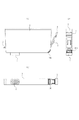
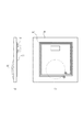
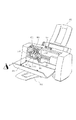
図1(a)、(b)および(c)は、それぞれ、本発明の第1の実施形態に係る液体収納容器であるインクタンクの側面図、正面図および底面図、図2はその側断面図である。なお、本説明において、インクタンクの正面とは、ユーザに向き合うことでその操作(着脱操作等)およびユーザへの情報提供(後述するLEDの発光)を可能とする面を言う。
1. Mechanical structure 1.1 Ink tank (Figs. 1-5)
1A, 1B, and 1C are a side view, a front view, and a bottom view, respectively, of an ink tank that is a liquid storage container according to the first embodiment of the present invention, and FIG. FIG. In the present description, the front surface of the ink tank refers to a surface that enables operations (attachment / detachment operation, etc.) and provision of information to the user (light emission of LEDs described later) by facing the user.
図1において、本実施形態のインクタンク1は正面側の下部に支持された支持部材3を有している。支持部材3はインクタンク1の外装と一体に、樹脂により形成されており、後述するタンクホルダへの装着操作等を行う際に被支持部を中心に変位可能な構成である。インクタンク1の背面側および正面側には、タンクホルダ側の係止部にそれぞれ係合可能な第1係合部5および第2係合部6(本例では支持部材3に一体化されている)が設けられ、これらの係合によってインクタンク1のタンクホルダへの装着状態が確保される。この装着時の動作については図15により後述する。
In FIG. 1, an
インクタンク1の底面には、タンクホルダへの装着時に、後述する記録ヘッドのインク導入口と結合してインク供給を行うためのインク供給口7が設けられている。この底面と正面とが交わる部分にあって、支持部材3の支持部分の底面側には、本実施形態の主要部をなす基体が設けられている。基体の形状としてはチップ形状でも板状であっても良いが、以下では基板100として説明する。
An
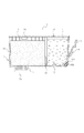
図2はインクタンク1の側断面図である。インクタンク1の内部は、支持部材3および基板100が設けられる正面側に位置するインク収納室11と、背面側に位置してインク供給口7に連通する負圧発生部材収納室12とに分割されており、両者は連通口13を介して接続されている。インク収納室11にはインクがそのまま貯留される一方、負圧発生部材収納室12には、インクを含浸保持するスポンジや繊維集合体等のインク吸収体15(以下、便宜的に多孔質部材と示す)が設けられている。この多孔質部材15は、記録ヘッドのインク吐出用のノズル部に形成されるメニスカスの保持力と平衡してインク吐出部からのインク漏れを防止するに十分で、かつ記録ヘッドのインク吐出動作が可能な範囲にある適切な負圧を発生するためのものである。
FIG. 2 is a side sectional view of the
負圧発生部材収納室12の上面には、記録ヘッドへのインク供給に伴って増大する負圧を緩和し、これを好ましい所定範囲に維持すべく外気を導入するための大気連通部12Aが設けられている。
The upper surface of the negative pressure generating
また、図2のインクタンク1は、後述の基板が配設されたインクタンク1の本体を用意してから、内部にインクを注入することで製造することができる。その方法を実施するためのインクの注入口は、例えばインク収納室11の上面に形成しておくことができる。そして、インク注入後に、注入口を封止部材11Aによって封止することができる。
The
インクタンク1の使用が開始され、インクが消費されはじめた以降、例えば収納するインク残量が実質的になくなってから、封止部材11Aを取り外し、またはこれを破壊することで注入口を再形成し、注射器等を用いてインクを注入してから、必要に応じ封止部材11Aまたはその代替部材で注入口を封止することも可能である。あるいは、そのような当初形成されていた注入口を利用する代わりに、例えばインク収納室11の上面の別の部位に開口を形成し、この開口を通してインクを注入してから、必要に応じてこれを封止することも可能である。例えば収納するインク残量が実質的になくなったインクタンクに対しそれらのようにしてインクを注入することも、本発明に係るインクタンク製造方法の実施に含まれる。
After the use of the
さらに、インク供給口7に対しては、製造されたインクタンク1の物流時や保管時等におけるインク漏出を防止するための封止部材7Aが着脱可能である。この封止部材7Aはキャップやテープ状の部材など、所定の封止性能が発揮され、かつ記録ヘッドへインクタンクの取り付けを行う際に取り外し可能なものであればいかなる形態でもよい。また、使用開始後において記録ヘッドからインクタンクを取り外した場合に、封止部材7Aまたはその代替部材でインク供給口7の封止を行うようにすることもできる。
Further, a sealing
なお、インクタンク1の内部構成は、このような多孔質部材の収納室とインクをそのまま貯留する収納室とに分かれた形態に限られない。例えば、多孔質部材がインクタンク内部空間の実質的に全体に充填されるものでもよい。また、負圧発生手段として多孔質部材を用いるのではなく、容積を拡張する方向に張力を発生するゴム等の弾性材料で形成した袋状部材内にインクをそのまま充填し、この袋状部材が発生する張力によって内部のインクに負圧を作用するようにしたものでもよい。さらには、インク収容空間の少なくとも一部を可撓性部材で構成し、その空間内にインクだけを収容するとともに、可撓性部材にばね力を作用させることで負圧を発生させるようにしたものでもよい。これらの場合も上述と同様のインク注入を行うことでインクタンクを製造することが可能である。また、これらの場合、記録ヘッドへのインク供給に伴って増大するインク収容空間内の負圧を緩和し、これを好ましい所定範囲に維持すべくインク収容空間内に外気を導入するための大気連通部が設けられるが、その大気連通部位を利用してインク注入を行うようにすることもできる。
The internal configuration of the
インク収納室11の底部には、インクタンク1の装置への装着時において装置側に設けられたインク残量検出用センサ(後述)と対向可能な部位に、被検出部17が設けられている。本実施形態において、インク残量検出用センサは発光部および受光部を有する光センサである。また、被検出部17は、透明もしくは半透明な材質からなり、かつインク非収納時には適切に発光部からの光を反射させて受光部(後述)に戻すことができるように形状,角度等が定められた斜面部を有したプリズム状のものである。
At the bottom of the
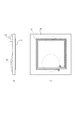
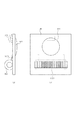
図3〜図5を用い、本実施形態の主要部である基板100の構成および機能について説明する。ここで、図3(a)および(b)は本発明の第1の実施形態に係るインクタンクに配置される基板の機能の概略を説明するための模式的側面図、図4(a)および(b)は、それぞれ、図3の主要部の拡大図およびそのIVb方向断面の矢視図、図5(a)および(b)は、それぞれ、第1の実施形態に係るインクタンクに取り付けられる制御基板100の一例を示す側面図および正面図である。
The configuration and function of the
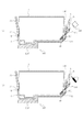
記録ヘッド105’を備えた記録ヘッドユニット105に一体化されているホルダ150の第1係止部155および第2係止部156に対し、インクタンク1の第1係合部5および第2係合部6がそれぞれ係合することで、インクタンク1がホルダ150に装着され、固定される。またこのとき、ホルダ150に設けられたアンテナ基板152と、インクタンクに設けられた基板100の外側に向かって位置する面に配線パターンにより設けられたループ状のアンテナ102(図5(b))とが近接して対向し、無線通信が可能となる。
The first
インクタンク1の内側に向かって位置する基板100の面には、LEDなど可視光を発生する第1発光部101と、この発光部を制御する制御素子103とが設けられており、アンテナ基板152よりインクタンク側アンテナ102を介して供給される電気信号により、制御素子103は第1発光部101の発光の制御を行う。なお、図5(a)は、制御素子103を基板100に実装した後に、保護用の封止剤でこれを被覆した状態を示している。また、インクタンクが収納しているインクの色やインク残量などの情報を記憶させておくメモリ素子を搭載する場合にも、これを同じ位置に実装して封止剤で被覆することができる。
On the surface of the
ここで、上述したように、インクタンク1の底面および正面をなす両面が交わる部分にあって、支持部材3の支持部分の下方には、本実施形態の主要部をなす基板100が配設されている。この配設部位において、インクタンク1には両面をつなぐ斜面が形成されている。従って、第1発光部101が発光すると、その一部は斜面に沿ってインクタンク1の正面側から外に向かって投光される。
Here, as described above, the
かかる配置とした基板100を用いることで、記録装置(ひいてはこれが接続されるコンピュータなどのホスト装置)だけでなく、ユーザに対しても、第1発光部101を兼用してインクタンク1に係る所定の情報を直接提示することが可能となる。すなわち、図3(a)に示すように、ホルダ150を搭載するキャリッジの走査範囲の端部にあって図の右上方向に投光される光を受容する位置に受光部を配置し、その部位にキャリッジが位置したときに第1発光部101の発光を制御することで、記録装置側は受光部の受光内容からインクタンク1に係る所定の情報を認識することが可能となる。また、例えば走査範囲の中央にキャリッジを位置させて第1発光部101の発光を制御することで、図3(b)に示すように、ユーザはその発光状態を目視することによりインクタンク1に係る所定の情報を認識することが可能となる。
By using the
インクタンク(液体収容容器)1の所定の情報とは、インクタンク1の装着状態の良否(すなわち装着が完全であるか否か)、装着位置の適否(インク色に対応して予め定められているホルダ上の装着位置に正しく装着されているか否か)、さらにはインク残量の有無(十分なインク量が残っているか否か)などであり、発光の有無や発光の状態(点滅など)によりそれらの情報の提示が可能となるのである。発光の制御およびそれに伴う情報提示の態様については、制御系の構成の説明の項において詳述する。
The predetermined information of the ink tank (liquid storage container) 1 is determined in advance according to whether or not the
上記基板100ないし第1発光部101の配置および動作に好ましい構成としては、図4(a)および(b)に示すものが挙げられる。すなわち、第1発光部101および制御素子103が設けられている基板100の面に対向するインクタンク1の部分には、第1発光部101により発光された光が第1受光部210やユーザの視界に円滑に到達するようにする目的で、少なくとも光軸(矢印)に沿って空間1Aを形成しておくことが望ましい。また、同じ目的のために、支持部材3の配設位置および形状を適切に定めることで、光軸が遮断されないようにする。さらに、ホルダ150には光軸を確保するための穴(もしくは光透過性の部分)150Hが設けられている。
Preferred configurations for the arrangement and operation of the
1.2 変形例(図6〜図13)
以上述べた構成は例示であって、第1発光部101を兼用して記録装置およびユーザに対しインクタンク1に係る所定の情報を提示することが可能であれば、適宜の変形を行うことができる。この項ではそのいくつかについて説明する。
1.2 Modification (FIGS. 6 to 13)
The above-described configuration is merely an example, and if it is possible to present the predetermined information related to the
図6(a)および(b)は、それぞれ、第1の実施形態に係るインクタンクに取り付けられる制御基板の変形例を示す側面図および正面図である。この例は、光が特に第1受光部210およびユーザの目の位置に向う方向に指向するようにしたものである。このためには、第1発光部101の姿勢を適切に定めた配置を行うほか、当該指向を行わせるための部材(レンズ等)を設けることができる。
6A and 6B are a side view and a front view, respectively, showing a modification of the control board attached to the ink tank according to the first embodiment. In this example, the light is particularly directed in the direction toward the first
図7(a)および(b)に示す例は、インクタンク1の内側に向かって位置する基板100の面には第1発光部101のみが位置するようになし、制御素子103をアンテナ102とともに基板100の外側に向かって位置する面に設けたものである。この結果、第1発光部101が発する光は制御素子103に遮られることがないので、基板100の面に沿って斜め上方だけでなく斜め下方にも向かうものとなる。
In the example shown in FIGS. 7A and 7B, only the first
図8はかかる構成の制御基板が配設されたインクタンクの使用態様を説明するための側面図である。この図から明らかなように、第1発光部101はユーザが目視可能な図の右上方向だけでなく、左下方向にも投光する。そこでこの左下方向に向かう光軸上に第1受光部210を配置することで、記録装置側がインクタンク1に係る所定の情報を受け取ることが可能となる。
FIG. 8 is a side view for explaining a usage mode of an ink tank provided with a control board having such a configuration. As is clear from this figure, the first
図9は図7の制御基板が配設されたインクタンクの使用態様の他の例を説明するための側面図である。この例は、インクタンク1の装置への装着時において、プリズム状の被検出部17に対向可能に、光センサ形態のインク残量検出用センサ117を記録装置に設ける場合に適している。すなわち、インク残量検出用センサ117は発光部117Aおよび受光部117Bを有し、インクタンク1のインク室11のインク残量が少ない状態では、発光部117Aからの光がプリズム状被検出部17で反射されて受光部117Bに戻されることで、装置はその状態を認識できる。本例はこの受光部117Bを第1発光部101からの光の受光部に兼用し、インクタンク1の装着の有無や適否をも装置が認識することができるようにしたものである。
FIG. 9 is a side view for explaining another example of usage of the ink tank provided with the control board of FIG. This example is suitable for the case where an ink remaining
図10(a)および(b)に示す例は、インクタンク1の内側に向かって位置する基板100の面に制御素子103を配置する一方、第1発光部101をアンテナ102とともに基板100の外側に向かって位置する面に設けたものである。この結果、第1発光部101が発する光は基板100の面から外側に向かう方向にも進行するものとなる。
In the example shown in FIGS. 10A and 10B, the
図11はかかる構成の制御基板が配設されたインクタンクの使用態様を説明するための側面図である。この図から明らかなように、第1発光部101はユーザが目視可能な図の右上方向だけでなく、右下方向にも投光する。そこでこの右下方向に向かう光軸上に第1受光部210を配置することで、記録装置側がインクタンク1に係る所定の情報を受け取ることが可能となる。
FIG. 11 is a side view for explaining a usage mode of an ink tank provided with a control board having such a configuration. As is clear from this figure, the first
以上の各構成においては、ユーザの目や受光部に向かう光軸が積極的に確保されるように、光軸を遮る部材の位置や形状を適切に定めたり、開口や透光性の部分を設けたりすることが好ましい。しかしこれによらずとも、ユーザの目や受光部に光を導く構成を採ることは可能である。 In each of the above configurations, the position and shape of the member that blocks the optical axis is appropriately determined, or the opening and the translucent part are set so that the optical axis toward the user's eyes and the light receiving unit is positively secured. It is preferable to provide it. However, it is possible to adopt a configuration that guides light to the user's eyes and the light receiving unit.
図12(a)および(b)は、そのための構成例を示すものであり、第1発光部101が発する光を所要の位置に向けて導くための光ファイバなどの導光性部材154を配設してある。すなわち、かかる導光性部材154によって、第1受光部210(図12(a))およびユーザの目(図12(b))に対し、インクタンク1に係る所定の情報を伝達することが可能となる。
FIGS. 12A and 12B show a configuration example for that purpose, and a
図13(a)および(b)は、それぞれ、インクタンクに取り付けられる制御基板のさらに他の例を示す側面図および正面図である。図10では第1発光部101は基板100の端部に寄せて配置していたが、この場合、アンテナ102をやや小さくする必要があるが、図13のように第1発光部101を基板100の内側に寄せて配置すれば、アンテナ102は最大の大きさを確保することが出来、好適な無線通信が可能になる。
FIGS. 13A and 13B are a side view and a front view showing still another example of the control board attached to the ink tank, respectively. In FIG. 10, the first
1.3 インクタンク取り付け部(図14〜図16)
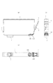
図14は第1の実施形態に係るインクタンクが着脱可能に構成された記録ヘッドユニットの一例を示す斜視図、図15(a)〜(c)はインクタンクを記録ヘッドユニットに装着する際の動作を説明するための図である。
1.3 Ink tank mounting part (FIGS. 14 to 16)
FIG. 14 is a perspective view illustrating an example of a recording head unit in which the ink tank according to the first embodiment is configured to be detachable. FIGS. 15A to 15C are views when the ink tank is mounted on the recording head unit. It is a figure for demonstrating operation | movement.
記録ヘッドユニット105は、概して、複数(図では4個)のインクタンクを着脱可能に保持するホルダ150と、底面側に配置される記録ヘッド105’(図14では不図示)とからなっている。そしてインクタンクをホルダ150に装着することで、ホルダ底部に位置する記録ヘッド側のインク導入口107とインクタンク側のインク供給口7とが結合し、両者間のインク連通路が形成される。
The
記録ヘッド105’としては、ノズルを構成する液路内に電気熱変換素子を設け、これに記録信号となる電気パルスを与えることによりインクに熱エネルギを付与し、そのときのインクの相変化により生じる発泡(沸騰)時の圧力をインクの吐出に利用するものを用いることができる。そして、後述するキャリッジ203に設けられた信号伝達用の電気接点部(不図示)と記録ヘッドユニット105側の電気接点部157とのコンタクトが行われ、配線部158を介して記録ヘッド105’の電気熱変換素子駆動回路への記録信号の伝達が行われる。また、電気接点部157からはアンテナ基板152に至る配線部159も延設されている。
As the
インクタンク1を記録ヘッドユニット105に装着する場合には、ホルダ150の上方でインクタンク1を取り扱い(図15(a))、インクタンク背面側に設けられた突起状の第1係合部5を、ホルダ背面側に設けられた貫通孔状の第1係止部155に挿通した状態でホルダ底面上に載置する(図15(b))。この状態でインクタンク1の正面側上端を矢印Pに示すように押下すると、インクタンク1は第1係合部5および第1係止部155の係合部分を回動支点として矢印R方向に回動し、インクタンク正面側が下方に変位してゆく。この過程で、インクタンク正面側の支持部材3に設けられた第2係合部5の側面がホルダ正面側に設けられた第2係止部156に押されながら、支持部材3も矢印Q方向に変位してゆく。
When the
そして第2係合部5の上面が第2係止部156の下方に至ると、支持部材3は自身の弾性力によってQ’方向に変位し、第2係合部5が第2係止部156によって係止される。
この状態(図15(c))では、第2係止部155が支持部材3を介してインクタンク1を水平方向に弾性的に付勢し、インクタンク1の背面がホルダ150の背面に当接する。
また、インクタンク1上方への変位は、第1係合部5が係合した第1係止部155および第2係合部6が係合した第2係止部156によって抑制される。これがインクタンク1の装着完了状態であり、このときインク供給口7およびインク導入口107、またアンテナ102およびアンテナ基板152上の本体側アンテナ220が近接して対向した状態となる。
When the upper surface of the second
In this state (FIG. 15C), the
Further, the upward displacement of the
「てこ」の作動にたとえると、図15(b)に示すような装着動作の過程では、第1係合部5および第1係止部155の係合部分が支点、インクタンク1の正面側が力点となる。インク供給口7およびインク導入口107の結合部分は作用点となって、これは力点と支点との間、好ましくは支点近くに位置する。従って、インク供給口7はインクタンク1の回動に伴って大きな力でインク導入口107に押し付けられる。両者の結合部分には通常、インク連通性の確保やインク漏洩の防止を目的としてフィルタ,吸収体,パッキンなど比較的可撓性に富む弾性部材が配設されている。
When compared to the operation of the “lever”, in the process of the mounting operation as shown in FIG. 15B, the engaging portion of the first engaging
従って、本例のような構成配置および装着動作を採用し、比較的大なる力をもってそれら部材を弾性変形させた状態とすることは、それらの配設目的に照らして好ましいことである。また、装着動作が完了すると、第1係合部5が係合した第1係止部155および第2係合部6が係合した第2係止部156によってインクタンク1の浮き上がりが阻止され、従ってそれら弾性部材の復元が抑制されるので、それらの部材は適切に弾性変形した状態に保持される。
Therefore, it is preferable in view of the arrangement purpose to adopt the arrangement and mounting operation as in this example and to elastically deform these members with a relatively large force. When the mounting operation is completed, the
本発明の第1実施形態または変形例に係るインクタンクの取り付け部分の構成は、図14に示したものに限られない。 The configuration of the attachment portion of the ink tank according to the first embodiment or the modification of the present invention is not limited to that shown in FIG.
図16を用いてこれを説明する。同図(a)はインクタンクからインクの供給を受けて記録動作を実行する記録ヘッドユニットの他の構成例及びこれを組み込むキャリッジの斜視図、(b)は両者を結合した状態を示す斜視図である。 This will be described with reference to FIG. FIG. 4A is a perspective view of another configuration example of a recording head unit that receives a supply of ink from an ink tank and executes a recording operation, and a carriage incorporating the same, and FIG. It is.
この例に係る記録ヘッドユニット405は、インクタンク全体を固定保持する上例のようなホルダ150と異なり、図16(a)に示すように、インクタンク正面側に対応したホルダ部分、およびここに配設されていた第2係止部およびアンテナ基板などを有していない。その他は上例とほぼ同様であり、底面上にはインク供給口7に接続されるインク導入口107を、また背面側には第1係止部155を、さらにその裏面には信号伝達用の電気接点部(不図示)を有している。
The
一方、シャフト417に沿って移動可能なキャリッジ415には、図16(b)に示すように、記録ヘッドユニット405を装着・固定するためのレバー419及び記録ヘッド側電気接点部と接続されている電気接点部418のほか、インクタンク正面側の構成に対応したホルダ部分が設けられている。すなわち、第2係止部156、アンテナ基板152およびコネクタへの配線部159はキャリッジ側に配設されている。
On the other hand, as shown in FIG. 16B, the
かかる構成にあって、図16(b)に示すように記録ヘッドユニット405をキャリッジ415に装着した状態とすればインクタンクの取り付け部分の全体が構成される。つまり図15と同様の装着動作を経て、インク供給口7およびインク導入口107の接合並びにアンテナ102および本体側アンテナ基板152の近接が行われて装着動作が完了する。
In this configuration, if the
1.4 記録装置(図17〜図18)
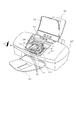
図17は、以上説明したインクタンクを装着して記録を行うインクジェットプリンタ200の外観を示す図であり、図18は、図17に示す本体カバー201を開放した状態を示す斜視図である。
1.4 Recording device (FIGS. 17 to 18)
FIG. 17 is a view showing an appearance of the
図17に示すように、本実施形態のプリンタ200は、記録ヘッドおよびインクタンクを搭載したキャリッジが走査のための移動をして記録を行う機構などプリンタの主要部分が、本体カバー201およびその他のケース部分によって覆われているプリンタ本体と、その前後にそれぞれ設けられる排紙トレイ203と、自動給紙装置(ASF)202とを備えたものである。また、本体カバーを閉じた状態および開いた状態の両方で本プリンタの状態を表示するための表示器、電源スイッチおよびリセットスイッチを備えた操作部213が設けられている。
As shown in FIG. 17, the
本体カバー201を開放した状態では、図18に示すように、ユーザは、記録ヘッドユニット105およびインクタンク1K、1Y、1M、1C(以下では、これらのインクタンクを同一の符号「1」で示す場合もある)を搭載したキャリッジ205が移動する範囲およびその周辺を見ることができる。実際は、本体カバー201を開けると、キャリッジ205が自動的に同図に示すほぼ中央の位置(以下、「タンク交換位置」ともいう)へ移動するシーケンスが実行され、ユーザは、このタンク交換位置でそれぞれのインクタンクの交換操作などを行うことができる。
In the state in which the
本実施形態のプリンタは、記録ヘッドユニット105に各色のインクに対応したチップ形態の記録ヘッド(不図示)が設けられ、これら各色の記録ヘッドがキャリッジ205の移動によって用紙などの記録媒体に対して走査を行い、この走査の間に記録媒体にインクを吐出して記録を行うものである。すなわち、キャリッジ205は、その移動方向に延在するガイド軸207と摺動可能に係合するとともに、キャリッジモータおよびその駆動力伝達機構によって、上述の移動をすることができる。そして、K、Y、M、Cのインクに対応したそれぞれの記録ヘッドでは、フレキシブルケーブル206を介して本体側の制御回路から送られる吐出データに基づいてインク吐出が行われる。また、紙送りローラや排紙ローラなどの紙送り機構が設けられ、自動給紙装置202から給紙された記録媒体(不図示)を排紙トレイ203まで搬送することができる。また、キャリッジ205には、インクタンクホルダを一体に備えた記録ヘッドユニット105が着脱自在に装着され、一方、この記録ヘッドユニット105に対してそれぞれのインクタンク1がカートリッジの形態にて着脱自在に装着される。すなわち、キャリッジ205に記録ヘッドユニット105を装着し、さらに記録ヘッドユニット105にインクタンク1を装着することが可能であり、本実施形態ではインクタンク1は記録ヘッドユニット105を介してキャリッジ205に着脱可能である。また、記録ヘッドユニット105にインクタンク1を装着することで、本発明液体供給システムの一実施形態が構成される。
In the printer of this embodiment, the
記録動作では、記録ヘッドが上記の移動によって走査しその間にそれぞれの記録ヘッドから記録媒体にインクを吐出して記録ヘッドにおける吐出口に対応した幅の領域に記録を行うとともに、この走査と次の走査の間に、上記紙送り機構によって上記幅に応じた所定量の紙送りを行うことにより、記録媒体に対して順次記録を行ってゆく。また、上記のキャリッジ移動による記録ヘッドの移動範囲の端部には、各記録ヘッドについてその吐出口が配設された面を覆うキャップなどの吐出回復ユニットが設けられている。これにより、記録ヘッドは所定の時間間隔で回復ユニットが設けられた位置へ移動して、予備吐出などの回復処理を行う。 In the recording operation, the recording head scans by the above movement, and during that time, ink is ejected from the respective recording heads to the recording medium to perform recording in a region having a width corresponding to the ejection port in the recording head. During scanning, the paper feeding mechanism feeds a predetermined amount of paper according to the width, thereby sequentially recording on the recording medium. In addition, an ejection recovery unit such as a cap is provided at the end of the moving range of the recording head by the carriage movement described above to cover the surface of each recording head on which the ejection port is provided. As a result, the recording head moves to a position where the recovery unit is provided at predetermined time intervals, and performs recovery processing such as preliminary ejection.
各インクタンク1のタンクホルダ部を備えた記録ヘッドユニット105には、前述したように、アンテナ基板が設けられており、アンテナは装着されるインクタンク1に設けられている基板のアンテナと近接する。これにより、それぞれのLED101について、図25〜図27にて後述されるシーケンスに従った点灯ないし点滅の制御が可能となる。
As described above, the
具体的には、上記のタンク交換位置では、それぞれのインクタンク1についてインク残量が少なくなったとき、その該当するインクタンク1のLED101を点灯もしくは点滅させる。また、キャリッジの移動範囲において、上述の回復ユニットが設けられた位置と反対側の端部付近には、受光素子を有した第1受光部210が設けられている。これにより、キャリッジ205の移動に伴ってそれぞれのインクタンク1のLED101がこの受光部210を通過する際にLED101を発光させ、その光を受光したときのキャリッジ205の位置に基づいてキャリッジ205におけるそれぞれのインクタンク1の位置を検出することができる。さらに、LEDの点灯などの制御の他の例として、上記タンク交換位置で、インクタンク1が正しく装着されたときにそのタンクのLED101を点灯させる制御を行う。これらの制御は、記録ヘッドのインク吐出などの制御と同様、フレキシブルケーブル206を介して本体側の制御回路から無線通信によって、それぞれのインクタンクに対して制御データ(制御信号)が送られることによって実行される。
Specifically, at the above-described tank replacement position, when the ink remaining amount of each
2.制御系の構成
2.1 全体構成(図19)
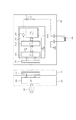
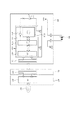
図19は、上述したインクジェットプリンタの制御系の構成例を示すブロック図であり、プリンタ本体におけるPCB(プリント配線基板)形態の制御回路とそれによって制御される、インクタンクのLEDの発光などに関する構成を主に示している。
2. Configuration of control system 2.1 Overall configuration (Fig. 19)
FIG. 19 is a block diagram showing a configuration example of the control system of the above-described inkjet printer, and a configuration relating to a control circuit in the form of a PCB (printed wiring board) in the printer main body and light emission of the LED of the ink tank controlled by the control circuit Is mainly shown.
図19において、制御回路300は本プリンタに関するデータ処理および動作制御を実行する。具体的には、CPU301は、ROM303に格納されているプログラムに従い、図25〜図28にて後述される処理などを実行する。また、RAM302は、CPU301による処理実行の際に、ワークエリアとして用いられる。
In FIG. 19, a
図19において模式的に示されるように、キャリッジ205に搭載された記録ヘッドユニット105は、ブラック(K)、イエロー(Y)、マゼンタ(M)、シアン(C)の各インクを吐出するための複数の吐出口が形成されたそれぞれの記録ヘッド105K、105Y、105M、105Cを備えている。そして、記録ヘッドユニット105のホルダには、これらの記録ヘッドに対応してインクタンク1K、1Y、1M、1Cが着脱自在に搭載される。
As schematically shown in FIG. 19, the
それぞれのインクタンク1には、前述したように、LED101、その表示制御回路、および、アンテナなどが設けられた基板100が取り付けられている。そして、インクタンク1が記録ヘッドユニット105に正しく装着されたとき、上記基板100上のアンテナが記録ヘッドユニット105において各インクタンク1に対向して共通に設けられたアンテナ基板と近接する。また、キャリッジ205に設けられたコネクタ(不図示)と本体側の制御回路300とはフレキシブルケーブル206を介して信号接続する。さらに、キャリッジ205に記録ヘッドユニット105が装着されることにより、キャリッジ205の上記コネクタと記録ヘッドユニット105の上記コネクタとが信号接続する。以上の接続、通信構成により、本体側の制御回路300とそれぞれのインクタンク1との間で信号の授受を行うことが可能となる。これにより、制御回路300は、図25〜図27にて後述されるシーケンスに従った点灯ないし点滅の制御を行うことができる。
As described above, the
記録ヘッド105K、105Y、105M、105Cにおけるそれぞれのインク吐出の制御についても、同様に、フレキシブルケーブル206、キャリッジ205のコネクタ、および記録ヘッドユニットのコネクタを介してそれぞれの記録ヘッドに設けられた駆動回路などが、本体側の制御回路300と信号接続し、これにより、制御回路300はそれぞれの記録ヘッドにおけるインク吐出などを制御することができる。
Similarly, with respect to the control of the respective ink ejections in the recording heads 105K, 105Y, 105M, and 105C, the drive circuits provided in the respective recording heads via the
キャリッジ205の移動範囲の一方の端部近傍に設けられる第1受光部210は、インクタンク1のLED101からの発光を受けて、それに応じた信号を制御回路300へ出力する。制御回路300は、後述のように、この信号に基づき、それぞれのインクタンク1のキャリッジ205における位置を判断することができる。また、キャリッジ205の移動経路に沿ってエンコーダスケール209が設けられるともに、キャリッジ205にはエンコーダセンサ211が設けられる。このセンサの検出信号はフレキシブルケーブル206を介して制御回路300に入力し、これにより、キャリッジ205の移動位置を知ることができる。この位置情報は、各記録ヘッド吐出制御に用いられるとともに、図25などにて後述される、インクタンク位置を検出する光認証処理において用いられる。さらに、キャリッジ205の移動範囲における所定の位置の近傍に設けられる第2発光/受光部214は、発光素子と受光素子とを有し、キャリッジ205に搭載されるそれぞれのインクタンク1のインク残量に係る信号を制御回路300に出力する。そして、制御回路300は、この信号に基づき、インク残量を検出することができる。
The first
2.2 接続部の構成(図20〜図24)
図20は、インクタンク1との通信のための信号配線の構成を、各インクタンクの基板100との関係で示す図である。
2.2 Configuration of connecting part (FIGS. 20 to 24)
FIG. 20 is a diagram showing the configuration of signal wiring for communication with the
図20に示すように、キャリッジ205上には制御回路208が搭載されており、制御回路208に対する本体側制御回路300からの信号配線は、例えば4本の信号線からなる。すなわち、制御回路208に対する信号配線は、電力供給にかかる電源信号線「VDD」およびアース信号線「GND」と、後述されるように、制御回路300から、LED101の点灯、点滅などの処理に関する制御信号(制御データ)などを送るための信号線「DATA」およびそのクロック信号線「CLK」の4本の信号線から構成される。本実施例においては4本の信号線による説明を行うが、本発明はこれに限定されるものでなく、その他、複数の制御信号線が必要になる場合もある。制御回路208は主にこれらの「DATA」および「CLK」信号を無線通信するための高周波変調、復調回路から成り、制御回路208はアンテナ基板152上のループ状のアンテナ220と、配線159で接続されている。アンテナ220からは、例えば短波帯の電磁波を生成し、インクタンク側のアンテナと通信する。制御回路208は本実施例ではキャリッジ205上に配置されているが、アンテナ基板152上に配置されても良い。
As shown in FIG. 20, a
一方、各インクタンク1の基板100には、本体側アンテナ220と無線通信するためのアンテナ102と、アンテナ102から受信した高周波信号を処理、またはアンテナ102から高周波信号を送信するための信号処理を行う制御部103およびそれによって動作するLED101が設けられている。
On the other hand, the
図21はこれら制御部などが設けられた基板の詳細を示す回路図である。同図に示すように、制御部103は、入出力制御回路(I/O CTRL)103A、メモリーアレイ103BおよびLEDドライバ103C、高周波変調/復調回路、電源回路103Eを有して構成される。高周波変調/復調回路、電源回路103Eを構成する復調回路は本体側のアンテナ220から受信した高周波信号を復調し、「DATA」、及び「CLK」信号を得る。また、電源回路は入出力制御回路(I/O CTRL)103A、メモリーアレイ103B、LEDドライバ103C、及びLED101に電力を供給するために、入力した電磁波から電源を生成する。また、変調回路はメモリアレイ103Bからの情報を本体側に送信するために信号を高周波に変調し、アンテナ102から電磁波を発生させる。
FIG. 21 is a circuit diagram showing details of a substrate on which these control units and the like are provided. As shown in the figure, the
入出力制御回路103Aは、復調された制御データに応じて、LED101の表示駆動やメモリーアレイ103Bに対するデータの書き込みおよび読み出しを制御する。メモリーアレイ103Bは、本実施形態ではEEPROMの形態のものであり、インク残量、収納するインクの色情報の他、そのインクタンクの固有番号や製造ロット番号などの製造情報等のインクタンク個体情報を記憶することができる。なお、色情報はインクタンクの出荷時または製造時に、その収納しているインクの色に対応して、メモリーアレイ103Bの所定のアドレスに書き込まれる。例えばこの色情報は、図23、図24にて後述されるように、インクタンクの識別情報(個体情報)として用いられ、これにより、インクタンクを特定してメモリーアレイ103Bに対するデータの書き込みやメモリーアレイ103Bからデータの読み出しを行い、また、そのインクタンクのLED101の点灯、消灯を制御することが可能となる。メモリーアレイ103Bに書き込まれ、また、読み出されるデータには、例えば、インク残量のデータがある。本実施形態のインクタンクには、前述したようにその底部にプリズムが設けられ、インクの残量が少なくなったときはこのプリズムを介して光学的にその旨を検出することができる。本実施形態では、これに加え、制御回路300は、吐出データに基づいて記録ヘッドごとの吐出数をカウントし、それに基づいてインクタンクごとのインク残量を計算する。そして、この残量情報をそれぞれ対応するインクタンクのメモリーアレイ103Bに書き込み、また、読み出す処理を行う。これにより、メモリーアレイ103Bはその時点のインク残量の情報を保持することができ、この情報は、例えば、上記プリズムを用いたインク残量検出と併用したより精度の高い残量検出に用いられたり、装着されたインクタンクが新しいものか、あるいは一度用いられて再装着されたものであるかなどを判断するために用いられたりする。
The input /
LEDドライバ103Cは、入出力制御回路103Aから出力される信号がオンのときLED101に電源電圧を印加するよう動作し、これにより、LED101を発光させる。従って、入出力制御回路103Aから出力される信号がオンの状態にあるとき、LED101は点灯状態となり、上記信号がオフの状態にあるとき、LED101は消灯状態となる。
The
図22は、図21に示した基板100の構成の変形例を示す回路図である。この変形例が図21に示す例と異なる点は、LED101に対して電源電圧を印加する構成において、電源がインクタンクの基板100内部に設けられたVDD電源パターンから供給されるものである。制御部103は半導体基板上にまとめて作りこまれることが一般的であり、この半導体基板上の接続端子をLED接続端子のみとした構成である。接続端子数少なくすることで、半導体基板の占有面積に大きく影響するので、半導体基板のコストダウンにつながるものである。
FIG. 22 is a circuit diagram showing a modified example of the configuration of the
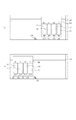
図23は、上述したメモリーアレイ103Bに対するデータの書き込みおよび読み出しの動作をそれぞれ説明するためのタイミングチャートであり、図24は、LED101の点灯および消灯の動作をそれぞれ説明するタイミングチャートである。
FIG. 23 is a timing chart for explaining the data writing and reading operations for the
図23に示すように、メモリーアレイ103Bへの書き込みでは、本体側の制御回路300からアンテナ220、102を介し、インクタンク1の制御部103における入出力制御回路103Aに対し、信号「DATA」(図20)を介して「開始コード+色情報」、「制御コード」、「アドレスコード」、「データコード」の各データ信号が、クロック信号CLKに同期してこの順で送られてくる。「開始コード+色情報」は、その「開始コード」信号によって、一連のデータ信号の始まりを意味し、また、「色情報」信号によってこの一連のデータ信号の対象となっているインクタンクを特定する。なお、ここでのインクの「色」とはY、M、C等のインク色だけでなく濃度の異なるインクをも含むものである。
As shown in FIG. 23, in writing to the
「色情報」は、同図に示すように、インクの色「K」、「C」、「M」、「Y」に対応したコードを有しており、入出力制御回路103Aは、このコードが示す色情報とメモリーアレイ103Bに格納されている自身の色情報とを比較し一致しているときにのみ、それ以降のデータ信号を取り込む処理を行い、一致しないときは、それ以降のデータ信号の取り込みを無視する処理を行う。これにより、図20に示した共通の信号「DATA」をアンテナを介して、本体側からデータ信号をそれぞれのインクタンクに共通に送っても、それに上述の色情報を含めることによってインクタンクを特定することができ、書き込み、読み出し、LEDの点灯、消灯など、その後のデータ信号に基づく処理を、その特定したインクタンクに関してのみ行うことが可能となる。この結果、4つのインクタンクに対して共通のデータ信号を介して送信されるデータによってデータの書き込みなどのほか、LEDの点灯、消灯の制御を行うことができ、これらの制御に要する信号の数を本発明のように少なくすることが可能となる。なお、このような共通のデータ信号を用いる構成は、インクタンクの数に限定されずに同じものとすることができることは、以上の説明からも明らかである。
As shown in the figure, the “color information” has codes corresponding to the ink colors “K”, “C”, “M”, “Y”, and the input /
本実施形態の「制御コード」は、図23に示すように、後述するLEDの点灯、消灯制御に用いられる「OFF」、「ON」のコードと、メモリーアレイに対する読み出しおよび書き込みを示すそれぞれ「READ」および「WRITE」のコードを有している。本書き込み動作では、「WRITE」のコードがインクタンクを特定する上記「色情報」のコードの後に続くことになる。次の「アドレスコード」は、書き込み先であるメモリーアレイのアドレスを示し、最後の「データコード」は書き込む内容を表している。 As shown in FIG. 23, the “control code” of the present embodiment includes “OFF” and “ON” codes used for LED on / off control, which will be described later, and “READ” indicating reading and writing to the memory array. ”And“ WRITE ”codes. In this writing operation, the “WRITE” code follows the “color information” code for specifying the ink tank. The next “address code” indicates the address of the memory array that is the write destination, and the last “data code” indicates the content to be written.
なお、「制御コード」が表す内容は上記の例に限られないことはもちろんであり、例えば、ベリファイコマンド、連続読み出しコマンドなどに関する制御コードを加えて用いることもできる。 Note that the content represented by the “control code” is not limited to the above example, and for example, a control code related to a verify command, a continuous read command, or the like can be added.
読み出しでは、上記の書き込みの場合とデータ信号の構成は同じであり、また、「開始コード+色情報」のコードは、上記の書き込みの場合と同様、総てのインクタンクの入出力制御回路103Aによって取り込まれ、それ以降のデータ信号は「色情報」が一致したインクタンクの入出力制御回路103Aだけが取り込む。異なる点は、アドレスコードによってアドレスを指定した後、最初のクロック(図23では13クロック目)の立ち上がりに同期して、読み出したデータの出力が行われる。複数のインクタンクのデータ信号が、このような共通の本体側のデータ信号と通信していても、読み出したデータが他の入力信号とぶつからないように入出力制御回路103Aが調停を行っているのである。
In reading, the configuration of the data signal is the same as in the case of the above writing, and the code of “start code + color information” is the input /
LED101の点灯または消灯では、図24に示すように、上記と同様、先ず、「開始コード+色情報」のデータ信号が、本体側からアンテナを介して入出力制御回路103Aに送られてくる。上述したように、「色情報」によってインクタンクが特定され、その後に送られてくる「制御コード」に基づくLED101の点灯、消灯は特定されたインクタンクのみで行われる。点灯、消灯にかかる「制御コード」は、図23にて上述したように、「ON」または「OFF」のコードがあり、「ON」によってLED101の点灯が行われ、「OFF」によって消灯が行われる。すなわち、制御コードが「ON」のとき、入出力制御回路103Aは、図22にて前述したように、LEDドライバ103Cに対してオン信号を出力し、それ以降もその出力状態を維持する。逆に、制御コードが「OFF」のとき、入出力制御回路103Aは、LEDドライバ103Cに対してオフ信号を出力し、それ以降もその出力状態を維持する。なお、LED101の点灯または消灯の実際のタイミングは、図24に示す各データ信号についてクロックCLKの7クロック目以降に行われる。
When the
同図に示す例では、最初、同図の最左端のデータ信号にあるように、ブラックKのインクタンクが特定されて、インクKのタンクのLED101が点灯されている。次に、2番目のデータ信号の「色情報」はマゼンタインクMを指定するものであり、「制御コード」は点灯を指示するものであるから、インクKのタンクのLED101が点灯したまま、インクMのタンクのLED101も点灯する。そして、3番目のデータ信号は、インクKのタンクについて、「制御コード」が消灯を指示するものであるから、インクKのタンクについてのみそのLED101が消灯する。
In the example shown in the figure, first, as shown in the leftmost data signal in the figure, the black K ink tank is specified, and the
LEDの点滅制御は、上記の説明からも分かるように、本体側の制御回路300が、点灯と消灯の「制御コード」をそれぞれ含むデータ信号をそのインクタンクを特定して送ることによって可能となる。その場合に、その信号を送る周期を定めることによって、点滅の周期を制御することができる。
As can be understood from the above description, the blinking control of the LED is made possible by the
2.3 制御手順(図25〜図31)
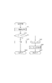
図25は、以上説明した本実施形態の構成に基づくインクタンクの着脱に関する制御手順を示すフローチャートであり、特に、本体側の制御回路300による各インクタンク1のLED101の点灯、消灯の制御を示すものである。
2.3 Control procedure (FIGS. 25 to 31)
FIG. 25 is a flowchart showing a control procedure related to the attachment and detachment of the ink tank based on the configuration of the present embodiment described above. In particular, the control of the
図25に示す処理は、ユーザが本実施形態のプリンタの本体カバー201を開いたとき、所定のセンサによってこれを検知して起動される処理である。本処理が起動されると、先ず、ステップS101で、インクタンク着脱処理を実行する。
The process shown in FIG. 25 is a process that is activated when a user opens the
図26は、このインクタンク着脱処理の詳細を示すフローチャートである。同図に示すように、着脱処理では、先ず、ステップS201で、キャリッジ205を移動するとともにそのとき搭載されているそれぞれのインクタンクについて状態情報(インクタンクの個体情報報)を取得する。取得される状態情報としてはそのときのインク残量などであり、これらがそのインクタンクの固有番号とともに、メモリーアレイ103Bから読み出される。そして、ステップS202で、キャリッジ205が図18にて説明したインクタンク交換位置に到達したか否かを判断する。
FIG. 26 is a flowchart showing details of the ink tank attaching / detaching process. As shown in the figure, in the attaching / detaching process, first, in step S201, the
キャリッジ205がインクタンク交換位置に到達したと判断すると、ステップS203でインクタンク装着確認制御を行う。
If it is determined that the
図27は、この装着確認制御の詳細を示すフローチャートである。先ず、ステップS301で、キャリッジ205に搭載されるインクタンクの数を示すパラメータNを設定するとともに、このインクタンクの数に応じてLEDの発光を確認するためのフラグF(k)を初期化する。本実施形態では、Nとして、K、C、M、Yのインクタンクの数で4が設定される。これに従い、F(1)、k=1〜4、の4つのフラグが用意され、これらが総て初期化されてその内容が“0”とされる。
FIG. 27 is a flowchart showing details of the attachment confirmation control. First, in step S301, a parameter N indicating the number of ink tanks mounted on the
次に、ステップS302で上記フラグのインクタンクの装着判定順序に関る変数Aを1に設定し、ステップS303で、A番目のインクタンクについて装着確認制御を行う。この制御は、ユーザがインクタンクを記録ヘッドユニット105のホルダ150に正しい位置に装着することにより、前述したホルダ150のアンテナ基板152とインクタンクのアンテナ102とが通信し、これにより、本体側の制御回路300が、前述したように、インクタンクの個体情報である色情報によってインクタンクを特定しつつ、その特定したタンクのメモリーアレイ103Bに格納されている色情報を順次読み出す動作である。また、上記特定するための色情報は、それまでに既に読み出されているものについては、用いないことはもちろんである。さらに、本制御では、この読み出した色情報が、本処理が起動された後、それまでに読み出された色情報と異なるものか否かの判断も行う。
Next, in step S302, the variable A relating to the ink tank mounting determination order of the flag is set to 1, and in step S303, mounting confirmation control is performed for the Ath ink tank. In this control, when the user mounts the ink tank in the correct position on the
そして、ステップS304では、色情報を読み出すことができ、かつその色情報がそれまでに読み出されたものと異なるとき、その色情報のインクタンクがA番目のインクタンクとして装着されたと判断する。それ以外の場合は、A番目のインクタンクが装着されていないと判断する。尚、ここで説明するA番目というのは単にインクタンクの判定を行う順番を説明するものであり、インクタンクの装着位置を示す順番ではない。A番目のインクタンクが装着されていると判断したときは、ステップS305で、そのフラグF(A)、すなわち、用意された4つのフラグF(k)、k=1〜4のうち、k=Aに該当するフラグ(A)の内容を“1”とし、図24にて上述したようにして、該当する色情報のインクタンク1のLED101を点灯する。装着されていないと判断したときは、ステップS311で、そのフラグF(A)の内容を“0”とする。
In step S304, when the color information can be read out and the color information is different from those read out so far, it is determined that the ink tank of the color information is attached as the Ath ink tank. In other cases, it is determined that the A-th ink tank is not attached. Note that the A-th described here simply describes the order in which the ink tanks are determined, not the order in which the ink tanks are mounted. If it is determined that the Ath ink tank is installed, in step S305, the flag F (A), that is, of the four prepared flags F (k), k = 1 to 4, k = The content of the flag (A) corresponding to A is set to “1”, and the
次に、ステップS306で、変数Aを1インクリメントし、ステップS307で、この変数AがステップS301で設定したN(本実施形態のプリンタの場合はN=4)より大きいか否かを判断する。ここで、変数AがN以下であると判断したときは、ステップS303以降の処理を繰り返す。また、変数AがNより大きいと判断したときは、4つのインクタンク総てについて装着確認制御が終了したとして、ステップS308で、本体カバー201が開放された状態か否かを、上記のセンサの出力に基づいて判断する。すなわち、本体カバーが閉じた状態であるときは、ユーザが、例えば、インクタンクのいくつかを未装着あるいは装着が不完全なままカバーを閉じた可能性があるとして、ステップS312で異常状態のステータスを図26の処理ルーチンへ返して本処理を終了する。
Next, in step S306, the variable A is incremented by 1. In step S307, it is determined whether or not the variable A is greater than N (N = 4 in the case of the printer of the present embodiment) set in step S301. Here, when it is determined that the variable A is equal to or less than N, the processes after step S303 are repeated. When it is determined that the variable A is greater than N, it is determined that the attachment confirmation control has been completed for all four ink tanks. In step S308, whether the
ステップS308で、本体カバー201が開いた状態であると判断したときは、4つのフラグF(k)、k=1〜4、の総てについてその内容が“1”か否か、すなわち、総てのインクタンクについて、LED101の点灯がされたか否かを判断する。いずれかのインクタンクのLED101が点灯していないと判断したときは、ステップS302以降の処理を繰り返す。すなわち、ユーザが、LED101が点灯していないインクタンクについて、装着し、または装着動作をやり直し、そのインクタンクのLEDが点灯するまで、上記の処理を繰り返す。
If it is determined in step S308 that the
総てのインクタンクのLEDが点灯されたと判断したときは、ステップS310で正常終了動作を行い、本処理を終了し、処理は図26に示す処理ルーチンに戻る。図28(a)は、総てのインクタンクについて正しく装着され、それぞれのLEDが点灯した状態を示す図である。 When it is determined that all the ink tank LEDs have been lit, a normal end operation is performed in step S310, the process ends, and the process returns to the process routine shown in FIG. FIG. 28A is a diagram showing a state in which all ink tanks are correctly mounted and each LED is lit.
再び、図26を参照すると、ステップS203のインクタンク装着確認制御を上記のように実行した後、ステップS204で、その制御正常終了したか否か、すなわち、正常にインクタンクが装着されたか否かを判断する。装着が正常と判断したときは、ステップS205で操作部213の表示器(図17、図18)を、例えばグリーンに点灯し、ステップS206で正常終了して図25に示す処理ルーチンに戻る。また、装着が異常と判断したときは、ステップS207で操作部213の表示器を、例えば、オレンジで点滅し、ステップS208で異常終了して図25に示す処理ルーチンに戻る。記録装置を制御するホストPCが接続されている場合は、同時にPCモニタを通して装着異常表示を行うこともできる。
Referring to FIG. 26 again, after the ink tank mounting confirmation control in step S203 is executed as described above, in step S204, whether or not the control is normally completed, that is, whether or not the ink tank is normally mounted. Judging. When it is determined that the mounting is normal, the display (FIGS. 17 and 18) of the
図25において、ステップS101のインクタンク着脱処理を終了すると、ステップS102で、上記着脱処理が正常終了したか否かを判断する。異常終了であると判断したときは、ステップS108で、ユーザが本体カバー201を開けるのを待ち、カバー201が開けられたことによってステップS101の処理が起動され、図26にて説明した処理を繰り返す。
In FIG. 25, when the ink tank attaching / detaching process in step S101 is completed, it is determined in step S102 whether the attaching / detaching process has been normally completed. If it is determined that the process has ended abnormally, in step S108, the process waits for the user to open the
ステップS102で、着脱処理が正常に終了したと判断したときは、ステップS103で、ユーザが本体カバー201を閉じるのを待ち、ステップS104でカバー201が閉じられたか否かを判断する。ここで、本体カバーが閉じられたと判断したときは、ステップS105の光認証処理に移行する。この際、図28(b)に示すように、本体カバー201が閉じられたことを検出すると、キャリッジ205は光認証のための位置へ移動するとともに、点灯されているそれぞれのインクタンクのLED101を消灯する。
If it is determined in step S102 that the attaching / detaching process has been completed normally, in step S103, the process waits for the user to close the
光認証処理は、正常に装着されたインクタンクそれぞれが正しい位置に装着されているか否かを判断する処理である。本実施形態では、インクタンクの装着位置について、例えば、インクタンクと装着位置の形状を他のインクのインクタンクが装着できないような形状とし、それぞれの色のインクタンクに対応して装着位置を定めるような構成をとらないことから、それぞれの色のインクタンクについて本来の位置でないところに誤って装着される可能性がある。このため、本光認証処理を行い、誤って装着されている場合は、ユーザにその旨を知らせるものである。これにより、特に、インクタンクの形状を色ごとに異ならせることなく、インクタンクの製造の効率化や低コスト化を図ることができる。 The optical authentication process is a process for determining whether or not each of the normally installed ink tanks is installed at the correct position. In the present embodiment, for example, the ink tank mounting position is set such that the ink tank and the mounting position cannot be mounted with ink tanks of other inks, and the mounting positions are determined corresponding to the ink tanks of the respective colors. Since such a configuration is not adopted, there is a possibility that the ink tanks of the respective colors are erroneously attached to places that are not the original positions. For this reason, this optical authentication process is performed, and if it is worn by mistake, the user is informed accordingly. Thereby, in particular, it is possible to increase the efficiency and reduce the cost of manufacturing the ink tank without changing the shape of the ink tank for each color.
図29(a)〜(d)および図30(a)〜(d)は、この光認証処理を説明する図である。 FIGS. 29A to 29D and FIGS. 30A to 30D are diagrams illustrating this optical authentication process.
図29(a)に示すように、先ず、第1受光部210に対して、図中左側から右側へ移動キャリッジ205を開始する。そして、最初に、イエローインクのインクタンク1Yが装着されるべき位置のインクタンクが第1受光部210に対向する位置で、インクタンク1YのLED101を発光させる(図24にて説明したように、実際は点灯し所定時間後消灯すること、以下、本認証処理では同様)。インクタンク本来の正しい位置に装着されているとき、第1受光部210はLED101の発光を受光することができ、制御回路300は、その装着位置にはインクタンク1Yが正しく装着されていると判断する。
As shown in FIG. 29A, first, the moving
キャリッジ205を移動しつつ、同様にして、図29(b)に示すように、マゼンタインクのインクタンク1Mが装着されるべき位置のインクタンクが第1受光部210に対向する位置で、インクタンク1MのLED101を発光させる。同図に示す例は、インクタンク1Mが正しい位置に装着されていて第1受光部210はその発光を受光することを示している。順次、図29(b)〜(d)に示すように、判断する装着位置を変えながら発光を行って行く。これらの図は、正しい位置に装着されている例を示している。
Similarly, while moving the
これに対し、図30(b)に示すように、マゼンタインクのインクタンク1Mが装着されるべき位置にシアンインクのインクタンク1Cが誤って装着されているときは、第1受光部210に対向しているインクタンク1CのLED101は発光せず、別の位置に搭載されているインクタンク1MのLED101が発光する。この結果、このタイミングでは、第1受光部210は受光できないことから、制御回路300は、その装着位置にはインクタンク1M以外のインクタンクが装着されていると判断する。これに対応して、図30(c)に示すように、シアンインクのインクタンク1Cが装着されるべき位置にマゼンタインクのインクタンク1Mが誤って装着されており、第1受光部210に対向しているインクタンク1MのLED101は発光せず、別の位置に搭載されているインクタンク1CのLED101が発光する。
On the other hand, as shown in FIG. 30B, when the
以上説明した光認証処理を行うことにより、制御回路300は本来の位置に装着されていないインクタンクを特定することができる。また、装着されるべき位置に正しいインクタンクが装着されていなかった場合には、その装着位置において、他の3色のインクタンクを順に発光させる制御を行うことによって、その装着位置に誤って何色のインクタンクが装着されてしまったかを特定することもできる。
By performing the optical authentication process described above, the
図25において、上述したステップS105の光認証処理の後、ステップS106でこの処理が正常終了したか否かを判断する。光認証が正常終了したと判断したときは、ステップS107で、操作部213の表示器を例えばグリーンに点灯して、本処理を終了する。一方、正常の終了でないと判断したときは、ステップS109で操作部213の表示器を例えばオレンジで点滅するとともに、ステップS110で、ステップS105で特定した、本来の正しい位置に装着されていないインクタンクのLED101を、例えば点滅あるいは点灯する。これにより、ステップS108で、ユーザが本体カバー201を開けたとき、本来の正しい位置に装着されていないインクタンクを知ることができ、正しい位置への再装着を促すことができる。
In FIG. 25, after the optical authentication process in step S105 described above, it is determined in step S106 whether or not this process has been completed normally. When it is determined that the optical authentication has been normally completed, the display unit of the
図31は、本実施形態にかかる記録処理を示すフローチャートである。本処理では、先ず、ステップS401で、インク残量確認処理を行う。この処理は、これから記録しようとしているジョブについて、記録データからその記録量を求め、この量とそれぞれのインクタンクの残量とを比較して、上記ジョブの記録に十分な量があるか否かを確認する処理である。なお、この処理では、上記のインク残量は、制御回路300でそのときの残量としてカウントして求めたものを用いることができる。
FIG. 31 is a flowchart showing recording processing according to the present embodiment. In this process, first, in step S401, an ink remaining amount confirmation process is performed. In this process, for the job that is going to be recorded, the recording amount is obtained from the recording data, and this amount is compared with the remaining amount of each ink tank. It is a process to confirm. In this process, the ink remaining amount obtained by counting the remaining amount at that time by the
ステップS402では、上記の確認処理に基づいて記録に必要なインク量があるか否かを判断する。十分なインク量があるときは、ステップS403で記録動作を行い、ステップS404で操作部213の表示器をグリーンに点灯して正常終了を行う。一方、ステップS402で十分なインク量がないと判断したときは、ステップS405で、操作部213の表示器をオレンジに点滅するとともに、ステップS406で、インク残量が少ないインクタンク1のLED101を点滅または点灯させて、異常終了する。記録装置を制御するホストPCが接続されている場合は、同時にPCモニタを通してインク残量表示を行うこともできる。
In step S402, it is determined whether there is an ink amount necessary for recording based on the above confirmation processing. When there is a sufficient amount of ink, the recording operation is performed in step S403, and the display of the
3.他の実施形態(図32〜図54)
上述の第1の実施形態では、インクタンク背面側にある第1係合部5をホルダ奥側の第1係止部155に挿通し、インクタンク正面側を押下しつつ挿通部分を回動支点としてインクタンク1を回動させながら装着動作を行う構成であった。これにとって好ましい基板100の配設位置は上述のように回動支点から離れた正面側に位置し、またこれに伴って、第1受光部210およびユーザの目に投光するのに兼用される第1発光部101も基板100に一体化した構成とした。
3. Other embodiments (FIGS. 32 to 54)
In the first embodiment described above, the
しかし、基板にとって好ましい配設位置と発光部に求められる配設位置とが、インクタンクやその取り付け部の構成に応じて異なる場合があり、その場合には基板および発光部をそれぞれ適宜の位置に配設し得る。すなわち、両者は必ずしも一体化されたものでなくてもよい。 However, the preferred arrangement position for the substrate and the arrangement position required for the light emitting part may differ depending on the configuration of the ink tank and its mounting part, in which case the substrate and the light emitting part are respectively placed at appropriate positions. It can be arranged. That is, the two do not necessarily have to be integrated.
図32(a)〜(c)は、本発明の他の実施形態に係るインクタンクおよびその取り付け部の構成例およびその装着動作を説明するための図である。 FIGS. 32A to 32C are views for explaining an example of the configuration of an ink tank and its mounting portion according to another embodiment of the present invention and the mounting operation thereof.
図32(a)において、本実施形態のインクタンク501には、正面上部にLEDなどの発光部601、上面奥側にパッド602が設けられた基板600が配置されている。従って、発光部601が発光すると、正面側から投光される。そこで、キャリッジの走査範囲の端部にあって図の左方向に投光される光を受容する位置に受光部620を配置し、その部位にキャリッジが位置したときに発光部601の発光を制御することで、記録装置側は受光部の受光内容からインクタンク501に係る所定の情報を認識することが可能となる。また、例えば走査範囲の中央にキャリッジを位置させて発光部601の発光を制御することで、ユーザはその発光状態を目視することによりインクタンク501に係る所定の情報を認識することが可能となる。
In FIG. 32A, the
記録ヘッドユニット605は、図32(c)に示すように、複数(図では2個)のインクタンクを着脱可能に保持するホルダ650と、底面側に配置される記録ヘッド605’とからなっている。そしてインクタンク501をホルダ650に装着することで、ホルダ底部に位置する記録ヘッド側のインク導入口607とインクタンク底部に位置するインク供給口507とが結合し、両者間のインク連通路が形成される。ホルダ650は、インクタンク501を装着する際の回動中心となる係合部655を正面側に、装着完了位置にインクタンク501を係止する係止部656を背面側上部に有している。また、係止部656近傍には、基板600のアンテナ602と通信するアンテナ652が設けられている。
As shown in FIG. 32C, the
インクタンク501を記録ヘッドユニット605に装着する場合には、ホルダ650の正面からインクタンク501を取り扱い、図32(b)に示すように、インクタンク背面下縁部をホルダ650の背面に押し当て、インクタンク正面の部位をホルダ650の係合部655に係合させた状態とする。この状態でインクタンク501の正面上部を背面方向に押圧すると、インクタンク501は係合部655を中心に矢印方向に回動しながらホルダ内に装着されて行く。図32(a)および(c)はインクタンク501の装着完了状態であり、このときインク供給口507およびインク導入口607、またアンテナ602および652が近接した状態となる。
When the
なお、ホルダ650側の係合部655および係止部656、あるいはこれらに対応したインクタンク501側の構成は適宜定めることができる。また、図示の例では基板600がインクタンク501の上面に平行な面として設けられているが、第1の実施形態のように斜面に配置することも可能であるのは勿論である。さらに、ホルダ650および関連した構成部材をヘッドユニットが有する構成としなくてもよい。
The engaging
図33は図32の構成の変形例を示す斜視図であり、ここではインクタンク501および記録ヘッド605’を一体に構成してなる2本の記録ヘッドユニット(液体収納カートリッジ)が示されている。本実施形態において、一方はブラックインク用、他方はイエロー、マゼンタおよびシアンインク用のカートリッジである。
FIG. 33 is a perspective view showing a modified example of the configuration of FIG. 32, in which two recording head units (liquid storage cartridges) are integrally formed of an
このような構成に対応して、上記ホルダ650と同様の構成をキャリッジに設ければよい。また、本例においては、正面側に位置する発光部601の制御回路はヘッドユニットの適宜の部位に設けた基板上に構成されたものでもよいが、記録ヘッド605’に一体化された駆動回路基板に制御回路を形成しておき、不図示の配線を介して発光部601への接続を行うこともできる。この場合、記録ヘッド605’の駆動回路および発光部601の制御回路は、配線部657さらには不図示の電気接点部を介して、キャリッジ側電気接点部に接続される。
Corresponding to such a configuration, a configuration similar to that of the
図34は、上述した他の実施形態にかかる構造を有したインクタンクを搭載して記録を行うプリンタを示す斜視図であり、本体カバーを開いた状態で示すものである。同図において、図17、図18等で説明した要素と同様の要素には同一の符号を付してその説明は省略する。 FIG. 34 is a perspective view showing a printer that performs recording by mounting an ink tank having a structure according to another embodiment described above, and shows a state in which a main body cover is opened. In the figure, the same elements as those described in FIGS. 17 and 18 are denoted by the same reference numerals, and the description thereof is omitted.
図34に示すように、ブラックインクを収納したインクタンク501Kとシアン、マゼンタ、イエローの各インクを収納する収納室を一体に形成したインクタンク501CMYがそれぞれ、キャリッジ205上の記録ヘッドユニット605のホルダに装着される。そして、各インクタンクにおいて、上述したように、LED601は基板とは別体に設けられ、インクタンクが装着された状態(のインクタンク交換位置)で、ユーザは正面にこれらLED601を見ることができる。また、このLEDの位置に対応して、受光部210が、キャリッジ205の移動範囲の一方の端部近傍に設けられている。
As shown in FIG. 34, an
図35(a)および(b)は、それぞれ、本発明のさらに他の実施形態に係るインクタンクの模式的側面図および正面図であり、第1の実施形態に係るインクタンクにおいて基板および発光部を別の位置に配設した例である。 FIGS. 35A and 35B are a schematic side view and a front view, respectively, of an ink tank according to still another embodiment of the present invention. In the ink tank according to the first embodiment, a substrate and a light emitting unit are respectively shown. This is an example in which is disposed at another position.
本例では、インクタンク正面上部にLEDなどの発光部101およびこれを搭載する基板100−2が設けられている。そして、上述と同様にキャリッジ側のアンテナ基板152との良好な通信およびインクからの保護にとって好ましい斜面部に配設した基板100と、基板100−2ないし発光部101とを、配線部159−2を介して接続することで、電気信号の授受を行うようになっている。なお、3Hは配線部159−2をインクタンク筐体に沿わせて配置するために支持部材3の根元部分に設けた穴である。
In this example, a
本例において、発光部101が発光すると、正面側から投光される。そこで、キャリッジの走査範囲の端部にあって図の右方向に投光される光を受容する位置に受光部210を配置し、その部位にキャリッジが位置したときに発光部101の発光を制御することで、記録装置側は受光部の受光内容からインクタンク1に係る所定の情報を認識することが可能となる。また、例えば走査範囲の中央にキャリッジを位置させて発光部101の発光を制御することで、図の括弧部分に示すように、ユーザはその発光状態をより容易に目視して、インクタンク1に係る所定の情報を認識することが可能となる。
In this example, when the
図36は図35の実施形態の変形例に係るインクタンクの模式的側面図である。本例では支持部材3の、特にユーザが操作する部分である操作部3Mの裏面側のインクタンク正面位置に、発光部101およびこれを搭載する基板100−2が設けられている。この例でも上例と同様の動作を行い、同様の効果を得ることができる。さらに本例では、例えば走査範囲の中央にキャリッジを位置させて発光部101の発光させたとき、支持部材3の操作部3Mにも光が照射されるので、ユーザはインクタンク交換その他の所要の操作をより直感的に理解することが可能となる。なお、操作部3Mの照射状態をより視認し易くするために、操作部3Mには適当量の光を透過または散乱させる部分が付加されていてもよい。
FIG. 36 is a schematic side view of an ink tank according to a modification of the embodiment of FIG. In this example, the
図37はさらに他の変形例に係るインクタンクの模式的側面図である。本例は、支持部材3の操作部3Mの正面側に発光部101およびこれを搭載する基板100−2を設けたものである。基板100と基板100−2ないし発光部101とは、支持部材3の根本部分に設けた穴3Hを介して支持部材3に沿わせた配線部159−2によって接続されている。この例でも、図36と同様の効果を得ることができる。
FIG. 37 is a schematic side view of an ink tank according to still another modification. In this example, the
なお、図35〜図37の構成において、フレキシブルプリントケーブル(FPC)を用いることで、基板100、配線部159−2および基板100−2を一体の部材とすることもできる。
In the configurations of FIGS. 35 to 37, the
以上の各実施形態は、吐出されたインク量に対応した量のインクが常に、プリントヘッドに対し言わば連続的に供給されるように供給系を構成した方式のもの(以下、連続供給方式という)にあって、キャリッジ等に搭載されて往復移動(主走査)する記録ヘッドに分離可能に取り付けられる形態のインクタンクを用いる構成に本発明を適用した場合について説明した。しかし本発明は、記録ヘッドに対して一体不可分に取り付けられたインクタンクを用いる構成に適用することもできる。そのような構成であっても、装着位置が異なれば異なる色のデータを受け取ったり、あるいは色の重なり順が設計とは異なることによって所望の記録品位が得られなくなることが考えられるからである。 In each of the above embodiments, the supply system is configured such that an amount of ink corresponding to the amount of ejected ink is always supplied continuously to the print head (hereinafter referred to as a continuous supply method). The case where the present invention is applied to a configuration using an ink tank that is detachably attached to a recording head mounted on a carriage or the like and reciprocally moved (main scanning) has been described. However, the present invention can also be applied to a configuration using an ink tank that is inseparably attached to the recording head. This is because even with such a configuration, it is conceivable that if the mounting position is different, data of different colors is received, or the order of color overlap is different from the design, so that a desired recording quality cannot be obtained.
また本発明は、キャリッジ上に搭載される記録ヘッドとは別体にインクタンクを記録装置の固定部位に取り付け、可撓性チューブを介してその固定インクタンクと記録ヘッドとを連結してインクを供給するチューブを用いる形態の連続供給方式に対しても適用できる。この形態において、インクタンクと記録ヘッドとの中間タンクとして機能するインクタンクが記録ヘッドないしキャリッジ上に搭載される構成であってもよい。 Further, according to the present invention, an ink tank is attached to a fixed portion of the recording apparatus separately from the recording head mounted on the carriage, and the fixed ink tank and the recording head are connected via a flexible tube to supply ink. The present invention can also be applied to a continuous supply system using a supply tube. In this embodiment, an ink tank that functions as an intermediate tank between the ink tank and the recording head may be mounted on the recording head or the carriage.
図38はかかる構成のインクジェット記録装置の一例を示す。 FIG. 38 shows an example of such an ink jet recording apparatus.
図において、710はカセット形態の給紙トレイであり、ここに積載された記録媒体は1枚ずつ分離・送給され、折り返し状の搬送経路に沿って搬送されてキャリッジ803に搭載された記録ヘッド(不図示)による記録領域を通過した後、排紙トレイ703に排出される。キャリッジ803はガイド軸807によって支持・案内され、図の左右方向に移動して記録ヘッドの記録走査を行わせる。
In the figure,
キャリッジ803には、各色インク用の記録ヘッドが搭載されるとともに、各色インク用の記録ヘッドにはそれぞれ専用の中間タンク(例えば、ブラックインク用、シアンインク用、マゼンタインク用およびイエローインク用のインクタンク811K〜811Y)が搭載される。また、これらの中間タンクには、装置の固定部位に着脱可能に設けられた比較的大容量の固定タンク701K〜701Yからそれぞれのインクが供給される。また、850はキャリッジ803の移動に追従するフレキシブルな追従部であり、キャリッジに搭載される各記録ヘッド等に所要の電気信号を伝達する電気配線部のほか、各固定タンクから各中間タンクへのインク供給チューブ群をまとめて総括的に示すものである。また、供給チューブ群は、不図示の連通管を介して、固定タンクとインク連通している。
The
記録動作に関しては上述した実施形態と同様であるが、本例では、上述の発光部101と同様の機能を果たす発光部801を固定タンク701K〜701Yのそれぞれに設けてある。また、発光部801に対応して、主走査の過程でその発光状態を検出可能な受光部810をキャリッジ803に搭載している。すなわち、これらの機構により、固定タンク701K〜701Yに関して、そのインク残量の有無や、装着の有無ないしは装着状態の良否につき、上述したのと同様、各固定タンクの状態を認識して所要の制御を行うことが可能となる。また、ユーザは発光部801の発光状態を視認することで、各固定タンクに関する情報を認識することができる。なお、固定タンクは着脱可能なものだけでなく、インク残量に応じてインクを補充することが可能な、実質的に半恒久的に取り付けられているものであってもよい。
Although the recording operation is the same as that of the above-described embodiment, in this example, the
さらに、このような構成は、チューブを用いた連続供給方式によるものだけでなく、記録ヘッドに比較的少量のインクを貯留する貯留部を備えるとともに、その貯留部に対し比較的大量のインクを貯留する供給源(上記と同様の固定タンク)から適切なタイミングで言わば間欠的にインクが供給されるように供給系を構成した方式のもの(間欠供給方式;所謂ピットイン供給方式)に対しても適用が可能である。 Further, such a configuration is not only based on a continuous supply method using a tube, but also includes a storage unit that stores a relatively small amount of ink in the recording head, and stores a relatively large amount of ink in the storage unit. Applicable also to a system (intermittent supply system; so-called pit-in supply system) in which the supply system is configured so that ink is intermittently supplied at an appropriate timing from a supply source (fixed tank similar to the above) Is possible.
その態様としては、中間タンクへのインク充填を行う際にのみ固定タンクとのインク供給系が空間的に接続される形態のものとすることができる。あるいは、図38と同様な両タンクの接続構造を採りつつも、その接続構造に電磁弁等を介挿し、これを適宜開閉制御することによって、両タンク間を流体的に絶縁および接続するような構成を有するものであってもよい。また中間タンク部に気液分離膜(気体は通すが液体を通さない膜)を設け、その膜を介してタンク内のエアーを吸引することで中間タンク内にインク供給を行うピットイン方式にも適用可能である。 As an aspect thereof, the ink supply system with the fixed tank can be spatially connected only when ink is filled into the intermediate tank. Or, while adopting the connection structure of both tanks similar to FIG. 38, an electromagnetic valve or the like is inserted into the connection structure, and the tank is fluidly insulated and connected by appropriately controlling the opening and closing thereof. It may have a configuration. In addition, a gas-liquid separation membrane (a membrane that allows gas to pass but not liquid) is provided in the intermediate tank, and it is also applied to a pit-in method that supplies ink into the intermediate tank by sucking air in the tank through the membrane. Is possible.
図39は本発明のさらに他の実施形態の制御部103などが設けられた基板100の詳細を示す回路図である。同図に示すように、制御部103は、入出力制御回路(I/O CTRL)103A、LEDドライバ103C、高周波変調/復調、電源回路103Eを有して構成される。
FIG. 39 is a circuit diagram showing details of the
入出力制御回路103Aは、本体側の制御回路300から高周波回路、アンテナを介して送られてくる制御データに応じて、LED101の表示駆動を制御する。
The input /
LEDドライバ103Cは、入出力制御回路103Aから出力される信号がオンのときLED101に電源電圧を印加するよう動作し、これにより、LED101を発光させる。従って、入出力制御回路103Aから出力される信号がオンの状態にあるとき、LED101は点灯状態となり、上記信号がオフの状態にあるとき、LED101は消灯状態となる。
The
本実施形態が図21に示す第一の実施形態と異なる点はメモリアレイ103Bが無いことである。メモリアレイ上に記憶されている個体情報(例えば色情報)が無い場合でもインクタンクを特定して、そのインクタンクのLED101の点灯、消灯を制御する方法を図40に示すタンミングチャートで以下に説明する。
This embodiment is different from the first embodiment shown in FIG. 21 in that there is no
本体側の制御回路300からインクタンク1の制御部103における入出力制御回路入出力制御回路103Aに対し、信号線DATA(図20)を介して「開始コード+色情報」、「制御コード」が、クロック信号CLKに同期して送られて来る。入出力制御回路入出力制御回路103Aは送られて来る「色情報」+「制御コード」を合わせて「コマンド」として識別し、LEDドライバ103Cへの出力信号のオン、オフを決定するコマンド識別部103Dを内部に有して構成される。1Kから1Yまでの各色のインクタンクにはそれぞれ異なるコマンド識別部103Dを有する制御部103が搭載されており、それぞれの色における点灯、消灯を制御するコマンドが図40に示すように構成されている。即ち、各色のコマンド識別部103D内には各色の個体情報(色情報)が含まれて構成されていることになり、これと入力された「コマンド」の「色情報」部分を比較、識別して各種の動作を制御する。これにより、例えばインクタンク1Kを点灯させる「K−ON」の色情報+制御コード「000100」を本体が開始コードと共に送信すると、インクタンク1Kのコマンド識別部103Dのみが識別し、インクタンク1Kのみが点灯する、という制御が可能になる。本実施形態では各色毎に制御部103を異ならせて構成する必要があるが、メモリアレイ103Bを搭載する必要が無い点で有利である。
“Start code + color information” and “control code” are sent from the
また、コマンド識別部103Dは図40に示すように各色毎のLED101の点灯、消灯のコマンドだけではなく、例えば全色のLED101を点灯、消灯させるコマンド「ALL−ON」、「ALL−OFF」や、各色を指定して、制御部103からの応答信号を出力させる「CALL」コマンドなど、複数のコマンドを識別する機能を持っていても良い。
Further, as shown in FIG. 40, the
さらに別の例として、本体側の制御回路300からインクタンク1に対して送られてくる色情報+制御コードからなるコマンドをインクタンク内の色情報(個体情報)と直接比較しない場合も本発明として適用可能である。つまり上記入力されたコマンドを制御部103において変換(演算)し、その変換した結果の値と、メモリアレイ103Bもしくはコマンド識別部103D内に保持する所定値とを比較して、その比較結果が所定の関係に対応した場合に点灯もしくは消灯等の制御を行っても良い。
As yet another example, the present invention also applies to a case where a command comprising color information + control code sent from the main body
また上記例とは別に、本体側から送られてくる信号を制御部103において変換(演算)し、さらにメモリアレイ103Bもしくはコマンド制御部103D内に保持する値も制御部103において変換(演算)し、変換した値同士を比較して、その比較結果が所定の関係に対応した場合に、点灯もしくは消灯等の制御を行っても良い。
Separately from the above example, the signal sent from the main body side is converted (calculated) by the
図41(a)および(b)は、それぞれ、インクタンクに取り付けられる制御基板100のさらに他のアンテナ形態を示す側面図および正面図である。アンテナ102は巻線コイル102Aにより構成され、基板100上の配線と2本のリード線102Bにより接続される。巻線コイル型のアンテナを用いることによって、電磁波から制御部103、およびLED101に供給する電源をより効率良く生成し、より高輝度なLED101の発光が可能となる。
FIGS. 41A and 41B are a side view and a front view showing still another antenna configuration of the
図42(a)、(b)および(c)は、それぞれ、更に他の実施形態に係るインクタンク1の側面図、正面図および底面図である。インクタンク1の底面、基板100の近傍にはボタン型のバッテリ108が配置されている。図43は本実施形態の制御部103などが設けられた基板100の詳細を示す回路図である。同図に示すように、バッテリ108はLED101のアノード側とGNDにそれぞれ接続されており、LED101の発光のための電力を供給する。アンテナ102を介して供給される電磁波から変換される電力は制御部103へのみ供給される。この形態にすることにより、制御部103より比較的大きな電力を必要とするLED101へはバッテリ108より供給されるため、電磁波から変換する電力は比較的小さくすることが出来るので、無線通信距離などの自由度が増し、本体側のアンテナ設置位置、アンテナ形態を比較的自由に選択することが出来る。
FIGS. 42A, 42B, and 42C are a side view, a front view, and a bottom view, respectively, of an
図44はバッテリ108からの電力を制御部103、およびLED101全体に供給する場合の回路を示す。この形態にすることにより、制御部103内部には電磁波から電力を変換する電源回路が不要となり、更に無線通信のための高周波変調回路にもより大きな電力を供給することが出来るため、無線通信の距離を大きく取ることが出来、更に本体側のアンテナ設置位置、アンテナ形態を自由に選択することが出来る。
FIG. 44 shows a circuit when power from the
図45(a)、(b)および(c)は、それぞれ、更に他の実施形態に係るインクタンク1の側面図、正面図および底面図である。基板100には2つの接触パッド109が配置されている。図46(a)および(b)は、それぞれ、本実施形態の基板を示す側面図および正面図である。インクタンク1に設けられた基板100の外側に向かって位置する面には電源供給のための接触パッド109がループ状アンテナ102の内側に配置されている。図47は本実施形態の制御部103などが設けられた基板100の詳細を示す回路図である。同図に示すように、電源供給用の接触パッドはLED101のアノード側とGNDにそれぞれ接続されており、LED101の発光のための電力を供給する。基板100の接触パッド109に接触する本体側コネクタ153は本体側アンテナ基板152上に配置され、本体側より電源が供給される。アンテナ102を介して供給される電磁波から変換される電力は制御部103へのみ供給される。この形態にすることにより、制御部103より比較的大きな電力を必要とするLED101へはバッテリ108より供給されるため、電磁波から変換する電力は比較的小さくすることが出来るので、無線通信距離などの自由度が増し、本体側のアンテナ設置位置、アンテナ形態を比較的自由に選択することが出来る。
45A, 45B, and 45C are a side view, a front view, and a bottom view, respectively, of an
図48は接触パッド109からの電源を制御部103、およびLED101全体に供給する場合の回路を示す。この形態にすることにより、制御部103内部には電磁波から電力を変換する電源回路が不要となり、更に無線通信のための高周波変調回路にもより大きな電力を供給することが出来るため、無線通信の距離を大きく取ることが出来、更に本体側のアンテナ設置位置、アンテナ形態を自由に選択することが出来る。
FIG. 48 shows a circuit when power from the
図49(a)および(b)は、それぞれ、更に他の実施形態の基板100を示す側面図および正面図である。インクタンク1に設けられた基板100の内側に向かって位置する面には電源供給のためのコンデンサ110が配置されている。図50および図51はそれぞれ、本実施形態の制御部103などが設けられた基板100の詳細を示す回路図である。同図に示すように、コンデンサ100は基板100内の電源ラインであるVDD、およびGNDに接続されている。このように構成することにより、LED101を発光させる場合にはコンデンサに蓄えたれた電荷を放電することで、発光時の比較的大きな電流を供給し、LED101を発光させない時間に本体側からの電磁波を受信して電源回路103Eによって電力に変換し、コンデンサに充電しておくことが出来る。また、近年では安価に提供されるようになった、電気二重層コンデンサを利用すれば、小型で大容量のコンデンサを搭載することが出来、LED101に供給する電力をより大きくすることができるため、更に好適である。図49ではインクタンク1に設けられた基板100の内側に向かって位置する面にコンデンサ110を配置したが、インクタンク1に設けられた基板100の外側に向かって位置する面に配置してもよい。また、図42に示した電池108の配置のように基板100の外にコンデンサを接続してもよい。この形態にすれば、より大型のコンデンサを接続することができる。
49A and 49B are a side view and a front view, respectively, showing a
図52(a)、(b)、(c)および(d)は、それぞれ、更に他の実施形態に係るインクタンク1の上面図、側面図、正面図および底面図である。本実施例ではインクタンク1の上面に基板100が配置されているが、図1に示す第一の実施例に比較して、インクタンク上面にはより大きな基板100を配設することができる。このため、より大きなアンテナ102を配設することができるため、記録装置本体側との無線通信がより有利となる。図52では基板100上に配線パターンによるループ状のアンテナを形成した例を示しているが、図41に示すような巻き線コイルを基板100に接続した形態にしても良い。また、LED101をインクタンク上面に配置することができるため、発光状態の目視確認をより容易に行うことができる。
FIGS. 52A, 52B, 52C, and 52D are a top view, a side view, a front view, and a bottom view of an
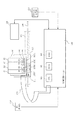
図53は本実施例の本体カバー201を開放した状態を示す斜視図である。また、図54は本実施例のインクジェットプリンタ本体の制御系の構成例を示すブロック図である。本実施例では無線通信の距離を比較的大きく取れるため、本体側のアンテナ220をインクジェットプリンタ本体内のどこに設置しても良い。図53ではキャリッジのホームポジション付近のキャリッジ上方に設置した例を示しているが、ホームポジションとは反対側や、第一実施例のようにキャリッジ上にアンテナ220を設置しても良い。
FIG. 53 is a perspective view showing a state in which the
1、1K、1C、1M、1Y、501 インクタンク
3 支持部材
3M 支持部材操作部
5 第1係合部
6 第2係合部
7、507 インク供給口
100、100−2 基板
101、601 発光部(LED)
102、220、602 アンテナ
152、652 アンテナ基板
602 パッド(コンタクト端子)
103 制御素子(制御部)
103A 入出力制御回路入出力制御回路
103B メモリーアレイ
103C LEDドライバ
103D コマンド識別部
103E 高周波変調/復調回路/電源回路
103F 高周波変調/復調回路
105、605 記録ヘッドユニット
105’、105K、105C、105M、105Y、605’ 記録ヘッド
107、607 インク導入口
108 電池
109 接点
110 コンデンサ
150、650 ホルダ
153 コネクタ
154 導光性部材
155 第1係止部
156 第2係止部
157 電気接点部
158、159、159−2 配線部
201 本体カバー
205 キャリッジ
206 フレキシブルケーブル
207 ガイド軸
208 高周波変調/復調回路
209 エンコーダスケール
210、810 第1受光部
211 エンコーダセンサ
213 操作部
214 第2発光/受光部
301 CPU
302 RAM
303 ROM
701K、701C、701M、701Y 固定タンク
811K、811C、811M、811Y 中間タンク
1, 1K, 1C, 1M, 1Y, 501
102, 220, 602
103 Control element (control unit)
103A I / O control circuit I /
302 RAM
303 ROM
701K, 701C, 701M, 701Y
Claims (19)
インク収納室と、
前記装置本体側アンテナと非接触で情報の通信が可能なタンク側アンテナと、
前記インク収納室に収納されているインクの色に関する色情報が記憶されているメモリと、
前記受光部へ向けて前記光を発光可能な発光部と、
(I)前記タンク側アンテナを介して前記装置本体側アンテナから受けた色情報および前記発光部の発光を制御するための制御情報と(II)前記メモリに記憶されている色情報とに基づいて、前記発光部の発光を制御する制御部と、
を有し、
前記タンク側アンテナ、前記メモリ、前記発光部及び前記制御部は、前記インク収納室の外に設けられていることを特徴とするインクタンク。 (A) an apparatus main body side antenna; (b) a mounting section having a plurality of mounting positions where the ink tank can be removably mounted; (c) a light receiving section for receiving light; and (d) the light receiving section. A determination unit that determines whether the ink tank is mounted at a correct mounting position in the mounting unit based on a light reception result of the unit, and an ink tank that is detachable from the mounting unit of the ink jet recording apparatus There,
An ink storage chamber;
A tank side antenna capable of communicating information in a non-contact manner with the apparatus main body side antenna;
A memory storing color information relating to the color of the ink stored in the ink storage chamber;
A light emitting unit capable of emitting the light toward the light receiving unit;
(I) Based on color information received from the apparatus main body side antenna via the tank side antenna, control information for controlling light emission of the light emitting unit, and (II) color information stored in the memory A control unit for controlling light emission of the light emitting unit;
Have
The ink tank, wherein the tank antenna, the memory, the light emitting unit, and the control unit are provided outside the ink storage chamber.
インク収納室と、
前記装置本体側アンテナと非接触で情報の通信が可能なタンク側アンテナと、
前記インク収納室に収納されているインクの色に関する色情報が記憶されているメモリと、
前記受光部へ向けて前記光を発光可能な前記発光部と、
(I)前記タンク側アンテナを介して前記装置本体側アンテナから受けた色情報および前記発光部の発光を制御するための制御情報と(II)前記メモリに記憶されている色情報に基づいて、前記発光部の発光を制御する制御部と、
を有し、
前記タンク側アンテナ、前記メモリ、前記発光部及び前記制御部は、前記インク収納室の外に設けられていることを特徴とするインクタンク。 (A) an apparatus main body side antenna; (b) a light receiving portion for receiving light; and (c) a carriage having a plurality of mounting positions to which the ink tank can be detachably mounted, the ink tank A carriage that can be moved to a predetermined position where there is a difference in the light reception result of the light receiving unit with respect to the light emission of the light emitting unit between when the light is mounted at the correct mounting position and when mounted at the wrong mounting position. And (d) determining whether or not the ink tank is mounted at the correct mounting position based on a light reception result of the light receiving unit with respect to light emission of the light emitting unit when the carriage is at the predetermined position. An ink tank detachable from the carriage of the ink jet recording apparatus,
An ink storage chamber;
A tank side antenna capable of communicating information in a non-contact manner with the apparatus main body side antenna;
A memory storing color information relating to the color of the ink stored in the ink storage chamber;
The light emitting unit capable of emitting the light toward the light receiving unit;
(I) Based on color information received from the apparatus main body side antenna via the tank side antenna and control information for controlling light emission of the light emitting unit, and (II) color information stored in the memory, A control unit for controlling light emission of the light emitting unit;
Have
The ink tank, wherein the tank antenna, the memory, the light emitting unit, and the control unit are provided outside the ink storage chamber.
インク収納室と、
前記装置本体側アンテナと非接触で情報の通信が可能なタンク側アンテナと、
前記インク収納室に収納されているインクの色に関する色情報が記憶されているメモリと、
前記受光部へ向けて前記光を発光可能な前記発光部と、
(I)前記タンク側アンテナを介して前記装置本体側アンテナから受けた色情報および前記発光部の発光を制御するための制御情報と(II)前記メモリに記憶されている色情報とに基づいて、前記発光部の発光を制御する制御部と、
を有し、
前記タンク側アンテナ、前記メモリ、前記発光部及び前記制御部は、前記インク収納室の外に設けられていることを特徴とするインクタンク。 (A) an apparatus main body side antenna, (b) a carriage on which a plurality of ink tanks can be removably mounted, (c) a light receiving unit for receiving light from the light emitting units of the plurality of ink tanks, d) a determination unit that determines whether or not the ink tank is mounted at a correct mounting position in the carriage based on a light reception result of the light receiving unit with respect to light emission of the light emitting unit. An ink tank removable from the carriage,
An ink storage chamber;
A tank side antenna capable of communicating information in a non-contact manner with the apparatus main body side antenna;
A memory storing color information relating to the color of the ink stored in the ink storage chamber;
The light emitting unit capable of emitting the light toward the light receiving unit;
(I) Based on color information received from the apparatus main body side antenna via the tank side antenna, control information for controlling light emission of the light emitting unit, and (II) color information stored in the memory A control unit for controlling light emission of the light emitting unit;
Have
The ink tank, wherein the tank antenna, the memory, the light emitting unit, and the control unit are provided outside the ink storage chamber.
前記制御部は、前記正しい装着位置に装着されていないと前記判定手段により判定されたインクタンクに収納されているインクの色に関連する前記色情報及び前記制御情報を前記装置本体側アンテナから前記タンク側アンテナを介して受け取り、当該受け取った前記色情報及び前記制御情報と前記メモリに記憶されている前記色情報とに基づいて前記発光部を点滅させるように構成されていることを特徴とする請求項1〜6のいずれかに記載のインクタンク。 The light emitting unit is an LED capable of emitting visible light,
The control unit obtains the color information and the control information related to the color of the ink stored in the ink tank determined by the determination unit as not being mounted at the correct mounting position from the apparatus main body side antenna. The light emitting unit is configured to blink on the basis of the color information and the control information received through the tank side antenna and the color information stored in the memory. The ink tank according to claim 1.
前記発光部は前記第1の面に設けられていることを特徴とする請求項8に記載のインクタンク。 The base has a first surface facing the inside of the ink tank and a second surface on the back side of the first surface;
The ink tank according to claim 8, wherein the light emitting unit is provided on the first surface.
Priority Applications (27)
| Application Number | Priority Date | Filing Date | Title |
|---|---|---|---|
| JP2005161316A JP4898147B2 (en) | 2005-06-01 | 2005-06-01 | Ink tank |
| CA2610170A CA2610170C (en) | 2005-06-01 | 2006-06-01 | Liquid container, liquid supplying system and circuit board for liquid container |
| SG201003815-6A SG162739A1 (en) | 2005-06-01 | 2006-06-01 | Liquid container, liquid supplying system and circuit board for liquid container |
| BRPI0610485-1A BRPI0610485A2 (en) | 2005-06-01 | 2006-06-01 | liquid container, liquid supply system, manufacturing method for manufacturing a liquid container, circuit board for a liquid container, recording device, and liquid container cartridge |
| CN2006800194759A CN101203387B (en) | 2005-06-01 | 2006-06-01 | Liquid container, liquid supplying system and circuit board for liquid container |
| EP06747232.4A EP1890882B1 (en) | 2005-06-01 | 2006-06-01 | Liquid container, liquid supplying system and circuit board for liquid container |
| TW095119790A TWI295973B (en) | 2005-06-01 | 2006-06-01 | Liquid container, liquid supplying system and circuit board for liquid container |
| UAA200714913A UA88700C2 (en) | 2005-06-01 | 2006-06-01 | equipment to recording apparatus |
| US11/911,913 US8075114B2 (en) | 2005-06-01 | 2006-06-01 | Liquid container, liquid supplying system and circuit board for liquid container |
| NZ562764A NZ562764A (en) | 2005-06-01 | 2006-06-01 | Liquid container with light emitting portion to emit light towards a receptor on a recording apparatus |
| PCT/JP2006/311472 WO2006129882A1 (en) | 2005-06-01 | 2006-06-01 | Liquid container, liquid supplying system and circuit board for liquid container |
| CN201110052663.4A CN102173209B (en) | 2005-06-01 | 2006-06-01 | Liquid container, liquid supplying system and circuit board for liquid container |
| AU2006253278A AU2006253278B2 (en) | 2005-06-01 | 2006-06-01 | Liquid container, liquid supplying system and circuit board for liquid container |
| KR1020077027960A KR100979823B1 (en) | 2005-06-01 | 2006-06-01 | Liquid container, printer and circuit board and liquid manufacturing method |
| KR1020107009744A KR100980161B1 (en) | 2005-06-01 | 2006-06-01 | Ink container and ink jet recording apparatus |
| MX2007014591A MX2007014591A (en) | 2005-06-01 | 2006-06-01 | Liquid container, liquid supplying system and circuit board for liquid container. |
| RU2007148920/12A RU2361743C1 (en) | 2005-06-01 | 2006-06-01 | Fluid container, fluid supply system and fluid container mounting plate |
| CN201110052673.8A CN102173210B (en) | 2005-06-01 | 2006-06-01 | Liquid container, liquid supplying system and circuit board for liquid container |
| ZA200709136A ZA200709136B (en) | 2005-06-01 | 2007-10-23 | Liquid container, liquid supplying system and circuit board for liquid container |
| IL187436A IL187436A (en) | 2005-06-01 | 2007-11-18 | Liquid container, liquid supplying system and circuit board for liquid container |
| EGNA2007001322 EG25054A (en) | 2005-06-01 | 2007-11-28 | Liquid container, liquid supplying system and circuit board for liquid container. |
| LVP-07-152A LV13689B (en) | 2005-06-01 | 2007-12-18 | Liquid container, liquid supplying system and circuit board for liquid container |
| NO20076621A NO20076621L (en) | 2005-06-01 | 2007-12-21 | Liquid container, liquid supply system and circuit board for liquid container |
| RU2009110861/12A RU2401204C1 (en) | 2005-06-01 | 2009-03-24 | Ink container |
| RU2010122781/12A RU2530398C2 (en) | 2005-06-01 | 2010-06-03 | Ink container |
| US13/246,778 US8382267B2 (en) | 2005-06-01 | 2011-09-27 | Liquid container, liquid supplying system and circuit board for liquid container |
| US13/748,479 US8740361B2 (en) | 2005-06-01 | 2013-01-23 | Liquid container, liquid supplying system and circuit board for liquid container |
Applications Claiming Priority (1)
| Application Number | Priority Date | Filing Date | Title |
|---|---|---|---|
| JP2005161316A JP4898147B2 (en) | 2005-06-01 | 2005-06-01 | Ink tank |
Related Child Applications (2)
| Application Number | Title | Priority Date | Filing Date |
|---|---|---|---|
| JP2010002101A Division JP4898926B2 (en) | 2010-01-07 | 2010-01-07 | Inkjet recording device |
| JP2011233346A Division JP5095004B2 (en) | 2011-10-24 | 2011-10-24 | Ink storage container and ink jet recording apparatus including ink storage container |
Publications (3)
| Publication Number | Publication Date |
|---|---|
| JP2006334885A JP2006334885A (en) | 2006-12-14 |
| JP2006334885A5 JP2006334885A5 (en) | 2008-07-17 |
| JP4898147B2 true JP4898147B2 (en) | 2012-03-14 |
Family
ID=36809180
Family Applications (1)
| Application Number | Title | Priority Date | Filing Date |
|---|---|---|---|
| JP2005161316A Expired - Fee Related JP4898147B2 (en) | 2005-06-01 | 2005-06-01 | Ink tank |
Country Status (20)
| Country | Link |
|---|---|
| US (3) | US8075114B2 (en) |
| EP (1) | EP1890882B1 (en) |
| JP (1) | JP4898147B2 (en) |
| KR (2) | KR100979823B1 (en) |
| CN (3) | CN102173209B (en) |
| AU (1) | AU2006253278B2 (en) |
| BR (1) | BRPI0610485A2 (en) |
| CA (1) | CA2610170C (en) |
| EG (1) | EG25054A (en) |
| IL (1) | IL187436A (en) |
| LV (1) | LV13689B (en) |
| MX (1) | MX2007014591A (en) |
| NO (1) | NO20076621L (en) |
| NZ (1) | NZ562764A (en) |
| RU (3) | RU2361743C1 (en) |
| SG (1) | SG162739A1 (en) |
| TW (1) | TWI295973B (en) |
| UA (1) | UA88700C2 (en) |
| WO (1) | WO2006129882A1 (en) |
| ZA (1) | ZA200709136B (en) |
Families Citing this family (34)
| Publication number | Priority date | Publication date | Assignee | Title |
|---|---|---|---|---|
| JP4125329B2 (en) | 2006-05-19 | 2008-07-30 | キヤノン株式会社 | Liquid storage container and liquid supply system including the container |
| JP4942161B2 (en) | 2006-06-30 | 2012-05-30 | キヤノン株式会社 | Liquid storage container and inkjet recording apparatus |
| US8066360B2 (en) * | 2007-04-18 | 2011-11-29 | Hewlett-Packard Development Company, L.P. | Fluid cartridge for a fluid supply system |
| DE102007051340B4 (en) * | 2007-10-26 | 2012-09-27 | 3T Supplies Ag | Ink cartridge with a device for signaling different filling states |
| US7862161B2 (en) * | 2007-10-29 | 2011-01-04 | Hewlett-Packard Development Company, L.P. | Ink detector viewable with the human eye |
| US7950791B2 (en) * | 2007-10-29 | 2011-05-31 | Hewlett-Packard Development Company, L.P. | Ink level detection by electronic means |
| JP5300364B2 (en) * | 2008-03-31 | 2013-09-25 | キヤノン株式会社 | Ink tank and ink jet recording apparatus |
| CN102161278B (en) * | 2008-06-30 | 2014-03-05 | 兄弟工业株式会社 | Adaptor for ink cartridge |
| JP5245654B2 (en) * | 2008-09-01 | 2013-07-24 | コニカミノルタIj株式会社 | Inkjet printer |
| DE102009026107A1 (en) * | 2009-07-06 | 2011-01-13 | Pelikan Hardcopy Production Ag | Ink cartridge and ink jet printer for receiving such an ink cartridge |
| CN101716855A (en) * | 2009-11-26 | 2010-06-02 | 珠海纳思达企业管理有限公司 | Cartridge, chip arranged on cartridge, printer matched with cartridge and method for confirming installation of cartridge |
| JP5565329B2 (en) | 2011-01-26 | 2014-08-06 | セイコーエプソン株式会社 | Liquid container to be mounted on liquid ejecting apparatus |
| US8559830B2 (en) * | 2011-05-11 | 2013-10-15 | Xerox Corporation | Lockout device and an indicator to ensure that the correct consumable is replaced in a printing device |
| CN102285242B (en) * | 2011-06-20 | 2013-10-09 | 珠海艾派克微电子有限公司 | Imaging box chip, imaging box and identification method for imaging box |
| JP5420024B2 (en) * | 2011-07-14 | 2014-02-19 | キヤノン株式会社 | Developer storage container, developer storage unit, process cartridge, electrophotographic image forming apparatus |
| JP5095004B2 (en) * | 2011-10-24 | 2012-12-12 | キヤノン株式会社 | Ink storage container and ink jet recording apparatus including ink storage container |
| CN103182847B (en) * | 2011-12-27 | 2015-11-25 | 珠海纳思达企业管理有限公司 | A kind of cartridge of ink-jet printer |
| CN102950901B (en) * | 2011-12-30 | 2015-06-03 | 珠海纳思达企业管理有限公司 | Inkjet cartridge group and method for detecting installed inkjet cartridge group |
| CN103182849B (en) * | 2011-12-30 | 2015-09-30 | 珠海艾派克微电子有限公司 | A kind ofly be installed to the print cartridge on printer and the storage chip on print cartridge removably |
| PL2799239T3 (en) | 2011-12-30 | 2016-12-30 | Inkjet cartridge, cartridge set, and cartridge set installation detection method | |
| CN103204005B (en) | 2012-01-12 | 2016-12-28 | 精工爱普生株式会社 | Box and printing material supply system |
| CN103204006B (en) | 2012-01-12 | 2017-04-26 | 精工爱普生株式会社 | Printing apparatus and printing material supply system |
| WO2013105143A1 (en) * | 2012-01-12 | 2013-07-18 | Seiko Epson Corporation | Cartridge and printing material supply system |
| US8708469B2 (en) | 2012-01-12 | 2014-04-29 | Seiko Epson Corporation | Cartridge and printing material supply system |
| DE102012104592A1 (en) * | 2012-05-29 | 2013-12-05 | Tigerline Gmbh | Liquid container e.g. ink cartridge arranged in output device e.g. inkjet printer, has control device to influence transmission of emitted light towards output device, such that light is transmitted in two different states |
| US9315344B1 (en) * | 2012-07-20 | 2016-04-19 | Amazon Technologies, Inc. | Container stacking configurations |
| CN103568567B (en) * | 2012-07-31 | 2015-12-02 | 珠海纳思达企业管理有限公司 | The control method of ink-jet box, ink-jet box group and ink-jet box |
| DE202013012393U1 (en) * | 2012-10-26 | 2016-09-05 | Zhuhai Ninestar Management Co., Ltd. | Control unit for controlling the light of an ink cartridge, circuit board and ink cartridge |
| US10753815B2 (en) | 2015-10-28 | 2020-08-25 | Hewlett-Packard Development Company, L.P. | Relative pressure sensor |
| JP6759644B2 (en) * | 2016-03-18 | 2020-09-23 | セイコーエプソン株式会社 | Liquid discharge device and drive circuit |
| CN112368151B (en) * | 2018-07-13 | 2022-09-06 | 惠普发展公司,有限责任合伙企业 | Fluid supply device |
| JP2020196183A (en) * | 2019-05-31 | 2020-12-10 | キヤノン株式会社 | Printer, printing system and method |
| USD944320S1 (en) * | 2019-12-24 | 2022-02-22 | Canon Kabushiki Kaisha | Ink cartridge for computer printer |
| CN115402008A (en) * | 2021-05-26 | 2022-11-29 | 精工爱普生株式会社 | Supply unit and liquid ejecting apparatus |
Family Cites Families (41)
| Publication number | Priority date | Publication date | Assignee | Title |
|---|---|---|---|---|
| JPS5751480A (en) | 1980-09-16 | 1982-03-26 | Hitachi Ltd | Ink ribbon cassette |
| JPS6416207A (en) | 1987-07-10 | 1989-01-19 | Tsubakimoto Chain Co | Positioning-stop device for linear induction motor driving truck |
| JPH04275156A (en) * | 1991-03-01 | 1992-09-30 | Tokyo Electric Co Ltd | Ink jet printer and ink jet cartridge therefor |
| JPH05340791A (en) | 1992-06-11 | 1993-12-21 | Canon Inc | Liquid level detecting means and ink jet recorder |
| JPH07323573A (en) | 1994-06-01 | 1995-12-12 | Murata Mach Ltd | Printer |
| US6238042B1 (en) * | 1994-09-16 | 2001-05-29 | Seiko Epson Corporation | Ink cartridge for ink jet printer and method of charging ink into said cartridge |
| US6494563B2 (en) * | 1997-12-25 | 2002-12-17 | Canon Kabushiki Kaisha | Ink jet element substrate and ink jet head that employs the substrate, and ink jet apparatus on which the head is mounted |
| US6151041A (en) | 1998-10-19 | 2000-11-21 | Lexmark International, Inc. | Less restrictive print head cartridge installation in an ink jet printer |
| US7110127B2 (en) * | 1999-04-20 | 2006-09-19 | Hewlett-Packard Development Company, L.P. | Method and apparatus for product regionalization |
| JP2000326604A (en) | 1999-05-18 | 2000-11-28 | Funai Electric Co Ltd | Printer |
| US7062651B1 (en) * | 1999-05-25 | 2006-06-13 | Silverbrook Research Pty Ltd | Network printer registration protocol |
| JP3755755B2 (en) | 1999-07-14 | 2006-03-15 | セイコーエプソン株式会社 | An ink cartridge, an ink jet recording apparatus using the ink cartridge, and a method for determining whether an ink cartridge can be attached to the apparatus. |
| US6302535B1 (en) | 2000-04-19 | 2001-10-16 | Hewlett-Packard Company | Ink container configured to establish reliable electrical connection with a receiving station |
| CA2343853A1 (en) | 2000-04-14 | 2001-10-14 | Muga Mochizuki | Semiconductor device, ink tank provided with such semiconductor device, ink jet cartridge, ink jet recording apparatus, method for manufacturing such semiconductor device, and communication system, method for controlling pressure, memory element, security system of ink jet recording apparatus |
| JP3745199B2 (en) * | 2000-06-16 | 2006-02-15 | キヤノン株式会社 | Ink tank provided with three-dimensional semiconductor element, and ink jet recording apparatus equipped with the ink tank |
| JP3814465B2 (en) * | 2000-06-16 | 2006-08-30 | キヤノン株式会社 | Inkjet recording system |
| ATE468227T1 (en) | 2000-06-16 | 2010-06-15 | Canon Kk | COMMUNICATION SYSTEM WITH SOLID STATE SEMICONDUCTOR COMPONENT, INK TANK, INK JET RECORDING DEVICE EQUIPPED WITH SUCH INK TANK. |
| US6685296B2 (en) | 2000-06-16 | 2004-02-03 | Canon Kabushiki Kaisha | Ink tank and ink jet recording apparatus provided with the same |
| CA2453883A1 (en) | 2000-06-16 | 2001-12-16 | Ichiro Saito | Ink jet recording apparatus utilizing solid semiconductor element |
| US20020063760A1 (en) | 2000-11-29 | 2002-05-30 | Dietl Steven J. | Remotely-powered ink cartridge identification system for an inkjet printer |
| TW503186B (en) | 2001-02-02 | 2002-09-21 | Benq Corp | Detecting device for ink storage |
| US6467888B2 (en) | 2001-02-21 | 2002-10-22 | Illinois Tool Works Inc. | Intelligent fluid delivery system for a fluid jet printing system |
| JP2002301829A (en) | 2001-04-04 | 2002-10-15 | Canon Inc | Ink jet recorder |
| JP3577012B2 (en) * | 2001-07-31 | 2004-10-13 | キヤノン株式会社 | Ink remaining amount detecting method and ink jet recording apparatus |
| RU2236947C2 (en) | 2001-11-28 | 2004-09-27 | Сейко Эпсон Корпорейшн | Contactless coupling between device and cartridge containing expendable material |
| MXPA02011493A (en) | 2001-11-28 | 2005-02-17 | Seiko Epson Corp | Non-contact communication between device and cartridge containing consumable component. |
| JP3826062B2 (en) | 2002-04-10 | 2006-09-27 | キヤノン株式会社 | ink cartridge |
| US7128380B2 (en) | 2002-04-10 | 2006-10-31 | Canon Kabushiki Kaisha | Recording liquid container, ink jet recording apparatus, and cartridge collecting apparatus |
| JP2003300358A (en) * | 2002-04-10 | 2003-10-21 | Canon Inc | Device for setting cartridge, and printer |
| US7140712B2 (en) | 2002-10-22 | 2006-11-28 | Seiko Epson Corporation | Liquid cartridge |
| JP4055152B2 (en) | 2002-10-22 | 2008-03-05 | セイコーエプソン株式会社 | Liquid cartridge |
| JP4103705B2 (en) | 2003-07-17 | 2008-06-18 | セイコーエプソン株式会社 | Liquid container |
| CA2461959C (en) | 2003-03-26 | 2012-07-24 | Seiko Epson Corporation | Liquid container |
| US7054570B2 (en) * | 2003-03-27 | 2006-05-30 | Ricoh Company, Ltd. | Image-forming apparatus |
| JP4337383B2 (en) * | 2003-04-10 | 2009-09-30 | セイコーエプソン株式会社 | Equipment capable of mounting consumable containers |
| JP2004338395A (en) * | 2003-04-21 | 2004-12-02 | Seiko Epson Corp | Information communication member, liquid container and liquid ejector comprising information communication member |
| MXPA04012681A (en) * | 2003-12-26 | 2005-07-01 | Canon Kk | Liquid container and liquid supplying system. |
| JP3793216B2 (en) * | 2003-12-26 | 2006-07-05 | キヤノン株式会社 | Liquid storage container, liquid supply system including the container, method for manufacturing the container, circuit board for the container, and liquid storage cartridge |
| JP4298629B2 (en) * | 2003-12-26 | 2009-07-22 | キヤノン株式会社 | Inkjet recording device |
| JP4125329B2 (en) | 2006-05-19 | 2008-07-30 | キヤノン株式会社 | Liquid storage container and liquid supply system including the container |
| JP4275156B2 (en) | 2006-07-26 | 2009-06-10 | 株式会社日立情報システムズ | Specific area network access control system, control method, and program thereof |
-
2005
- 2005-06-01 JP JP2005161316A patent/JP4898147B2/en not_active Expired - Fee Related
-
2006
- 2006-06-01 BR BRPI0610485-1A patent/BRPI0610485A2/en not_active Application Discontinuation
- 2006-06-01 NZ NZ562764A patent/NZ562764A/en not_active IP Right Cessation
- 2006-06-01 WO PCT/JP2006/311472 patent/WO2006129882A1/en active Application Filing
- 2006-06-01 US US11/911,913 patent/US8075114B2/en not_active Expired - Fee Related
- 2006-06-01 CN CN201110052663.4A patent/CN102173209B/en not_active Expired - Fee Related
- 2006-06-01 CN CN201110052673.8A patent/CN102173210B/en not_active Expired - Fee Related
- 2006-06-01 EP EP06747232.4A patent/EP1890882B1/en not_active Not-in-force
- 2006-06-01 KR KR1020077027960A patent/KR100979823B1/en not_active IP Right Cessation
- 2006-06-01 KR KR1020107009744A patent/KR100980161B1/en not_active IP Right Cessation
- 2006-06-01 CN CN2006800194759A patent/CN101203387B/en not_active Expired - Fee Related
- 2006-06-01 SG SG201003815-6A patent/SG162739A1/en unknown
- 2006-06-01 UA UAA200714913A patent/UA88700C2/en unknown
- 2006-06-01 CA CA2610170A patent/CA2610170C/en not_active Expired - Fee Related
- 2006-06-01 RU RU2007148920/12A patent/RU2361743C1/en not_active IP Right Cessation
- 2006-06-01 TW TW095119790A patent/TWI295973B/en active
- 2006-06-01 AU AU2006253278A patent/AU2006253278B2/en not_active Ceased
- 2006-06-01 MX MX2007014591A patent/MX2007014591A/en active IP Right Grant
-
2007
- 2007-10-23 ZA ZA200709136A patent/ZA200709136B/en unknown
- 2007-11-18 IL IL187436A patent/IL187436A/en not_active IP Right Cessation
- 2007-11-28 EG EGNA2007001322 patent/EG25054A/en active
- 2007-12-18 LV LVP-07-152A patent/LV13689B/en unknown
- 2007-12-21 NO NO20076621A patent/NO20076621L/en not_active Application Discontinuation
-
2009
- 2009-03-24 RU RU2009110861/12A patent/RU2401204C1/en not_active IP Right Cessation
-
2010
- 2010-06-03 RU RU2010122781/12A patent/RU2530398C2/en not_active IP Right Cessation
-
2011
- 2011-09-27 US US13/246,778 patent/US8382267B2/en not_active Expired - Fee Related
-
2013
- 2013-01-23 US US13/748,479 patent/US8740361B2/en not_active Expired - Fee Related
Also Published As
Similar Documents
| Publication | Publication Date | Title |
|---|---|---|
| JP4898147B2 (en) | Ink tank | |
| JP4115480B2 (en) | Liquid storage container | |
| JP4125329B2 (en) | Liquid storage container and liquid supply system including the container | |
| JP4298629B2 (en) | Inkjet recording device | |
| JP4942231B2 (en) | Inkjet recording device | |
| JP4659530B2 (en) | Ink tank holder and ink jet recording head cartridge | |
| JP5095004B2 (en) | Ink storage container and ink jet recording apparatus including ink storage container | |
| JP4898926B2 (en) | Inkjet recording device | |
| JP4420460B2 (en) | Ink tank substrate unit, ink tank comprising the substrate unit, and ink jet recording apparatus | |
| JP4993783B2 (en) | Ink tank |
Legal Events
| Date | Code | Title | Description |
|---|---|---|---|
| A521 | Request for written amendment filed |
Free format text: JAPANESE INTERMEDIATE CODE: A523 Effective date: 20080530 |
|
| A621 | Written request for application examination |
Free format text: JAPANESE INTERMEDIATE CODE: A621 Effective date: 20080530 |
|
| RD04 | Notification of resignation of power of attorney |
Free format text: JAPANESE INTERMEDIATE CODE: A7424 Effective date: 20100201 |
|
| RD01 | Notification of change of attorney |
Free format text: JAPANESE INTERMEDIATE CODE: A7421 Effective date: 20100630 |
|
| A977 | Report on retrieval |
Free format text: JAPANESE INTERMEDIATE CODE: A971007 Effective date: 20110817 |
|
| A131 | Notification of reasons for refusal |
Free format text: JAPANESE INTERMEDIATE CODE: A132 Effective date: 20110823 |
|
| A521 | Request for written amendment filed |
Free format text: JAPANESE INTERMEDIATE CODE: A523 Effective date: 20111024 |
|
| TRDD | Decision of grant or rejection written | ||
| A01 | Written decision to grant a patent or to grant a registration (utility model) |
Free format text: JAPANESE INTERMEDIATE CODE: A01 Effective date: 20111220 |
|
| A01 | Written decision to grant a patent or to grant a registration (utility model) |
Free format text: JAPANESE INTERMEDIATE CODE: A01 |
|
| A61 | First payment of annual fees (during grant procedure) |
Free format text: JAPANESE INTERMEDIATE CODE: A61 Effective date: 20111226 |
|
| FPAY | Renewal fee payment (event date is renewal date of database) |
Free format text: PAYMENT UNTIL: 20150106 Year of fee payment: 3 |
|
| LAPS | Cancellation because of no payment of annual fees |