KR100979823B1 - Liquid container, printer and circuit board and liquid manufacturing method - Google Patents
Liquid container, printer and circuit board and liquid manufacturing method Download PDFInfo
- Publication number
- KR100979823B1 KR100979823B1 KR1020077027960A KR20077027960A KR100979823B1 KR 100979823 B1 KR100979823 B1 KR 100979823B1 KR 1020077027960 A KR1020077027960 A KR 1020077027960A KR 20077027960 A KR20077027960 A KR 20077027960A KR 100979823 B1 KR100979823 B1 KR 100979823B1
- Authority
- KR
- South Korea
- Prior art keywords
- ink
- container
- antenna
- light emitting
- ink container
- Prior art date
Links
Images


Classifications
-
- B—PERFORMING OPERATIONS; TRANSPORTING
- B41—PRINTING; LINING MACHINES; TYPEWRITERS; STAMPS
- B41J—TYPEWRITERS; SELECTIVE PRINTING MECHANISMS, i.e. MECHANISMS PRINTING OTHERWISE THAN FROM A FORME; CORRECTION OF TYPOGRAPHICAL ERRORS
- B41J2/00—Typewriters or selective printing mechanisms characterised by the printing or marking process for which they are designed
- B41J2/005—Typewriters or selective printing mechanisms characterised by the printing or marking process for which they are designed characterised by bringing liquid or particles selectively into contact with a printing material
- B41J2/01—Ink jet
- B41J2/17—Ink jet characterised by ink handling
- B41J2/175—Ink supply systems ; Circuit parts therefor
- B41J2/17503—Ink cartridges
- B41J2/17543—Cartridge presence detection or type identification
- B41J2/17546—Cartridge presence detection or type identification electronically
-
- B—PERFORMING OPERATIONS; TRANSPORTING
- B41—PRINTING; LINING MACHINES; TYPEWRITERS; STAMPS
- B41J—TYPEWRITERS; SELECTIVE PRINTING MECHANISMS, i.e. MECHANISMS PRINTING OTHERWISE THAN FROM A FORME; CORRECTION OF TYPOGRAPHICAL ERRORS
- B41J2/00—Typewriters or selective printing mechanisms characterised by the printing or marking process for which they are designed
- B41J2/005—Typewriters or selective printing mechanisms characterised by the printing or marking process for which they are designed characterised by bringing liquid or particles selectively into contact with a printing material
- B41J2/01—Ink jet
- B41J2/17—Ink jet characterised by ink handling
- B41J2/175—Ink supply systems ; Circuit parts therefor
-
- B—PERFORMING OPERATIONS; TRANSPORTING
- B41—PRINTING; LINING MACHINES; TYPEWRITERS; STAMPS
- B41J—TYPEWRITERS; SELECTIVE PRINTING MECHANISMS, i.e. MECHANISMS PRINTING OTHERWISE THAN FROM A FORME; CORRECTION OF TYPOGRAPHICAL ERRORS
- B41J2/00—Typewriters or selective printing mechanisms characterised by the printing or marking process for which they are designed
- B41J2/005—Typewriters or selective printing mechanisms characterised by the printing or marking process for which they are designed characterised by bringing liquid or particles selectively into contact with a printing material
- B41J2/01—Ink jet
- B41J2/17—Ink jet characterised by ink handling
- B41J2/175—Ink supply systems ; Circuit parts therefor
- B41J2/17566—Ink level or ink residue control
- B41J2002/17573—Ink level or ink residue control using optical means for ink level indication
Abstract
본 발명은 복수의 액체 용기가 탈착식으로 장착될 수 있는 기록 장치에 탈착식으로 장착 가능한 액체 용기에 관한 것이고, 기록 장치는 장치 안테나 및 광수신기 수단을 포함하고, 액체 용기는 물리적인 접촉이 없이 장치 안테나와 통신 가능한 용기 안테나와, 적어도 액체 용기의 개별 정보를 저장할 수 있는 정보 저장부와, 발광부와, 용기 안테나를 통해 공급된 개별 정보를 표시하는 신호와 정보 저장부 내에 저장된 정보 사이의 대응성에 응답하여 발광부의 발광을 제어하기 위한 제어기를 포함한다.The present invention relates to a liquid container detachably mountable to a recording device in which a plurality of liquid containers can be detachably mounted, the recording device comprising a device antenna and an optical receiver means, wherein the liquid container is a device antenna without physical contact. Responding to a correspondence between a vessel antenna capable of communicating with, an information storage unit capable of storing at least individual information of the liquid container, a light emitting unit, a signal indicative of individual information supplied via the vessel antenna, and information stored in the information storage unit; And a controller for controlling light emission of the light emitting unit.
잉크 제트 프린터, 액체 용기, 발광부, 수광부, 안테나, 메모리 어레이 Ink jet printers, liquid containers, light emitters, light receivers, antennas, memory arrays
Description
본 발명은 액체 용기, 용기를 포함하는 액체 공급 시스템, 용기를 위한 제조 방법, 용기를 위한 회로 보드, 및 액체 수납 카트리지에 관한 것이다. 특히, 본 발명은 잉크 제트 기록에서 사용 가능하며, LED와 같은 발광 수단에 의해 잉크 용기의 잉크 잔량과 같은 액체 용기의 상태를 통보할 수 있는 액체 용기와, 용기를 포함하는 액체 공급 시스템과, 용기의 제조 방법과, 용기를 위한 회로 보드와, 용기를 포함하는 액체 수납 카트리지에 관한 것이다.The present invention relates to a liquid container, a liquid supply system including the container, a manufacturing method for the container, a circuit board for the container, and a liquid storage cartridge. In particular, the present invention can be used in ink jet recording, and is capable of informing the status of a liquid container, such as the remaining amount of ink in the ink container, by a light emitting means such as an LED, a liquid supply system including the container, and a container. And a liquid storage cartridge comprising a manufacturing method, a circuit board for a container, and a container.
최근 널리 사용되는 디지털 카메라에서, 카메라가 프린터(기록 장치)와 직접 연결된 채로 인쇄하기 위한 요구, 즉 무PC 인쇄가 증가하고 있다. 다른 증가하는 요구는 데이터를 전달하기 위해 디지털 카메라에 탈착식으로 장착 가능한 카드형 정보 메모리 매체를 프린터 내에 직접 설치하고, 이를 인쇄함으로써 인쇄하기 위한 것이다 (다른 무PC 인쇄). 대체로, 프린터의 잉크 용기 내의 잉크 잔량은 개인용 컴퓨터를 통해 디스플레이 상에서 점검된다. 무PC 인쇄의 경우에, 이는 가능하지 않다. 그러나, 잉크 용기 내의 잉크 잔량을 점검하는 능력은 무PC 인쇄에서도 필요하다. 이는 사용자가 잉크 용기 내의 잉크 잔량이 작다는 사실을 인식할 수 있 으면, 사용자가 인쇄 작업을 시작하기 전에 잉크 용기를 새로운 것으로 교환할 수 있어서, 시트 상으로의 인쇄 작업 도중의 인쇄 실패가 회피될 수 있기 때문이다.Background Art [0002] In recent widely used digital cameras, there is an increasing demand for printing cameras directly connected to a printer (recording device), that is, PC-free printing. Another increasing demand is to print by printing directly onto a printer and printing a card-like information memory medium detachably mountable to a digital camera to convey data (another PC-free printing). In general, the remaining ink level in the ink container of the printer is checked on the display by a personal computer. In the case of PC-free printing, this is not possible. However, the ability to check the remaining amount of ink in the ink container is necessary even in PC-free printing. This allows the user to recognize that the remaining ink level in the ink container is small, so that the user can exchange the ink container with a new one before starting the print job, so that printing failure during the print job on the sheet can be avoided. Because it can.
LED와 같은 디스플레이 요소를 사용하여 잉크 용기의 그러한 상태를 사용자에게 통보하는 것이 일반적이다. 예를 들어, 일본 특허 출원 공개 제평4-275156호는 기록 헤드와 일체인 잉크 용기가 잉크 잔량에 의존하여 2단계로 켜지는 2개의 LED 요소를 구비하는 것을 개시한다. 일본 특허 출원 공개 제2002-301829호 또한 잉크 용기가 잉크 잔량에 의존하여 켜지는 램프를 구비하는 것을 개시한다. 이는 또한 하나의 기록 장치에서 사용되는 4개의 잉크 용기가 각각 상기 램프를 구비하는 것을 개시한다.It is common to inform the user of such a condition of the ink container using a display element such as an LED. For example, Japanese Patent Application Laid-open No. Hei 4-275156 discloses that an ink container integrated with a recording head has two LED elements that are turned on in two stages depending on the remaining ink level. Japanese Patent Application Laid-Open No. 2002-301829 also discloses that the ink container has a lamp that is turned on depending on the remaining ink level. It also discloses that the four ink containers used in one recording apparatus each have the lamps.
또한, 높은 화상 품질에 대한 요구를 충족시키기 위해, 연홍색 잉크, 연청색 잉크 등이 종래의 4가지 컬러(검정, 황색, 마젠타, 및 시안) 잉크에 추가하여 사용된다. 또한, 적색 잉크 또는 청색 잉크와 같은 특수 컬러 잉크의 사용이 제안된다. 그러한 경우에, 7 - 8개의 컬러 잉크 용기가 잉크 제트 프린터 내에서 개별적으로 사용된다. 그 다음, 잉크 용기가 잘못된 위치에 장착되는 것을 방지하기 위한 메커니즘이 필요하다. 미국 특허 제6,302,535호는 캐리지와 잉크 용기들 사이의 결합 구성들이 서로 다르게 만들어지는 것을 개시한다. 그렇게 함으로써, 잉크 용기가 캐리지 상에 장착될 때, 잘못된 장착(부정확한 위치)이 방지된다.In addition, in order to meet the demand for high image quality, pale red ink, pale blue ink and the like are used in addition to the conventional four color (black, yellow, magenta, and cyan) inks. In addition, the use of special color inks such as red or blue inks is proposed. In such a case, seven to eight color ink containers are used individually in the ink jet printer. Then, a mechanism is needed to prevent the ink container from being mounted at the wrong position. U. S. Patent No. 6,302, 535 discloses that the coupling configurations between the carriage and the ink containers are made different. By doing so, when the ink container is mounted on the carriage, erroneous mounting (incorrect position) is prevented.
잉크 용기가 전술한 바와 같이 램프를 구비할 때에도, 주 조립체 측 제어기는 소량의 잉크를 수납한 것으로 인식되는 잉크 용기를 식별해야 한다. 이렇게 하기 위해, 올바른 램프를 켜기 위한 신호의 잉크 용기를 식별하는 것이 필요하다. 예를 들어, 잉크 용기가 틀린 위치 상에 장착되면, 소량의 잉크 잔량이 충분한 양의 잉크를 수납한 다른 잉크 용기에 대해 표시될 가능성이 있다. 그러므로, 램프와 같은 표시 장치에 대한 발광 제어는 잉크 용기들의 보유 위치의 정확한 정보를 가져야 한다.Even when the ink container has a lamp as described above, the main assembly side controller must identify the ink container which is recognized as having received a small amount of ink. To do this, it is necessary to identify the ink container of the signal for turning on the correct lamp. For example, if the ink container is mounted on the wrong position, there is a possibility that a small amount of remaining ink is displayed for another ink container containing a sufficient amount of ink. Therefore, the light emission control for the display device such as a lamp should have accurate information of the holding position of the ink containers.
잉크 용기들의 정확한 보유 위치를 보장하기 위한 구조에 관해, 보유부와 관련 잉크 용기들 사이의 상호 구성 관계가 보유 위치에 의존하여 다르게 만들어지는 구조가 있다. 그러나, 그러한 경우에, 잉크의 컬러 및/또는 종류에 의존하여 상이한 잉크 용기들을 제조하는 것이 요구되고, 그 결과 제조 효율 및/또는 비용의 측면에서 불리하다.Regarding the structure for ensuring the correct holding position of the ink containers, there is a structure in which the mutual configuration relationship between the holding portion and the associated ink containers is made different depending on the holding position. However, in such a case, it is required to produce different ink containers depending on the color and / or type of ink, which is disadvantageous in terms of manufacturing efficiency and / or cost.
이를 달성하기 위한 다른 구조로서, 캐리지의 보유 위치에서 잉크 용기의 전기 접속부와 주 조립체 측 전기 접속부 사이의 연결에 의해 폐쇄되는 회로의 신호 라인 등이 각각의 보유 위치에 대해 실질적으로 독립적으로 제공된다. 예를 들어, LED의 활성화를 제어하기 위해 잉크 용기로부터 잉크 용기의 잉크 컬러 정보를 판독하기 위한 신호 라인이 각각의 보유 위치에 대해 제공된다. 그러한 구조에서, 판독된 컬러 정보가 보유 위치와 맞지 않으면, 잉크 용기의 잘못된 장착이 구별된다.As another structure for achieving this, a signal line or the like of a circuit closed by the connection between the electrical connection of the ink container and the electrical connection on the main assembly side in the holding position of the carriage is provided substantially independently for each holding position. For example, a signal line for reading ink color information of the ink container from the ink container to control the activation of the LED is provided for each holding position. In such a structure, if the read color information does not match the holding position, wrong mounting of the ink container is distinguished.
그러나, 이러한 구조는 신호 라인의 개수를 증가시킨다. 전술한 바와 같이, 최근의 잉크 제트 프린터 등은 인쇄 품질을 개선하기 위해 매우 많은 종류의 잉크를 사용한다. 신호 라인의 개수의 증가는 특히 그러한 프린터에서 비용을 증가시킨다. 다른 한편으로, 배선 리드의 개수를 감소시키기 위해, 버스 연결을 사용하 는 소위 공통 신호 라인을 채용하는 것이 효과적이지만, 버스 연결로서의 그러한 공통 신호 라인의 단순 사용은 잉크 용기 또는 잉크 용기의 보유 위치를 결정할 수 없다.However, this structure increases the number of signal lines. As mentioned above, recent ink jet printers and the like use a very large number of inks to improve print quality. Increasing the number of signal lines increases the cost, especially in such printers. On the other hand, in order to reduce the number of wiring leads, it is effective to employ a so-called common signal line using a bus connection, but the simple use of such a common signal line as a bus connection has a bearing position of the ink container or ink container. Can't decide
따라서, 본 발명의 주요 목적은 LED와 같은 표시 장치의 발광 제어가 잉크 용기들을 위한 복수의 보유 위치에 대해 공통 안테나를 사용하여 비접촉식 통신을 통해 수행되는, 액체 용기, 용기를 포함하는 액체 공급 시스템, 용기를 위한 제조 방법, 용기를 위한 회로 보드, 및 액체 수납 카트리지를 제공하는 것이다. 본 발명의 다른 태양에 따르면, 표시 장치에 대한 발광 제어가 잉크 용기들의 보유 위치의 결정에 기초하여 실행되는, 액체 용기, 용기를 포함하는 액체 공급 시스템, 용기를 위한 제조 방법, 용기를 위한 회로 보드, 및 액체 수납 카트리지가 제공된다.Accordingly, a main object of the present invention is a liquid supply system including a liquid container, a container, wherein light emission control of a display device such as an LED is performed through contactless communication using a common antenna for a plurality of holding positions for ink containers, To provide a manufacturing method for a container, a circuit board for the container, and a liquid storage cartridge. According to another aspect of the present invention, a liquid container, a liquid supply system including a container, a manufacturing method for the container, a circuit board for the container, wherein light emission control for the display device is performed based on the determination of the holding position of the ink containers. , And a liquid storage cartridge.
본 발명의 일 태양에 따르면, 복수의 액체 용기가 탈착식으로 장착될 수 있는 기록 장치에 탈착식으로 장착 가능한 액체 용기가 제공되고, 상기 기록 장치는 장치 안테나 및 광수신기 수단을 포함하고, 상기 액체 용기는 물리적인 접촉이 없이 장치 안테나와 통신 가능한 용기 안테나와, 적어도 상기 액체 용기의 개별 정보를 저장할 수 있는 정보 저장부와, 발광부와, 상기 용기 안테나를 통해 공급된 개별 정보를 표시하는 신호와 상기 정보 저장부 내에 저장된 상기 정보 사이의 대응성에 응답하여 상기 발광부의 발광을 제어하기 위한 제어기를 포함한다.According to one aspect of the present invention, there is provided a liquid container detachably mountable to a recording device in which a plurality of liquid containers can be detachably mounted, the recording device comprising a device antenna and an optical receiver means, the liquid container being A container antenna capable of communicating with the device antenna without physical contact, an information storage unit capable of storing at least individual information of the liquid container, a light emitting unit, a signal indicative of individual information supplied through the container antenna, and the information And a controller for controlling light emission of the light emitting portion in response to correspondence between the information stored in the storage portion.
본 발명의 다른 태양에 따르면, 복수의 액체 용기가 탈착식으로 장착될 수 있는 기록 장치에 탈착식으로 장착 가능한 액체 용기가 제공되고, 상기 기록 장치는 장치 안테나 및 광수신기 수단을 포함하고, 상기 액체 용기는 물리적인 접촉이 없이 장치 안테나와 통신 가능한 용기 안테나와, 적어도 상기 액체 용기의 개별 정보를 저장할 수 있는 정보 저장부와, 광수신기 수단을 향해 광을 방출하기 위한 발광부와, 상기 용기 안테나를 통해 공급된 개별 정보를 표시하는 신호에 의해 표시되는 정보와 상기 정보 저장 수단 내에 저장된 상기 정보가 동일할 때, 상기 발광부의 발광을 제어하기 위한 제어기를 포함한다.According to another aspect of the present invention, there is provided a liquid container detachably mountable to a recording device in which a plurality of liquid containers can be detachably mounted, the recording device comprising a device antenna and an optical receiver means, the liquid container being A vessel antenna capable of communicating with the device antenna without physical contact, an information storage portion capable of storing at least individual information of the liquid container, a light emitting portion for emitting light towards the optical receiver means, and supplied through the vessel antenna And a controller for controlling light emission of the light emitting portion when the information displayed by the signal indicating the individual information is identical with the information stored in the information storage means.
그러한 구조에서, 발광부의 발광은 기록 장치 측에 제공된 안테나와 통신 가능한 잉크 용기(액체 용기)의 안테나를 통해 입력된 신호 및 잉크 용기의 정보에 대해 제어될 수 있다. 보유되는 잉크 용기들이 공통의 주 조립체 안테나를 사용하여 무선 통신을 통해 동일한 제어 신호를 수신하더라도, 정보와 맞는 잉크 용기만이 발광 제어를 수행할 수 있다. 그렇게 함으로써, 발광부의 발광 제어는 개별적으로 결정된 잉크 용기에 대해서만 가능하다. 예를 들어, 복수의 잉크 용기를 보유하는 캐리지가 이동할 때, 발광부는 순차적으로 소정의 위치에서 활성화된다. 이에 의해, 발광은 소정의 위치에서 검출된다. 그 다음, 발광이 검출되지 않은 잉크 용기는 틀린 위치에 장착된 것으로 인식된다. 그렇게 함으로써, 사용자는 잉크 용기를 올바른 위치로 재장착하도록 지시받을 수 있고, 이러한 방식으로, 잉크 용기들의 각각의 보유 위치가 검출될 수 있다.In such a structure, the light emission of the light emitting portion can be controlled with respect to the information of the ink container and the signal input through the antenna of the ink container (liquid container) that can communicate with the antenna provided on the recording apparatus side. Even if the ink containers held receive the same control signal via wireless communication using a common main assembly antenna, only the ink container matching the information can perform light emission control. By doing so, light emission control of the light emitting portion is possible only for individually determined ink containers. For example, when the carriage holding the plurality of ink containers moves, the light emitting portions are sequentially activated at predetermined positions. By this, light emission is detected at a predetermined position. Then, the ink container in which no light emission is detected is recognized as mounted in the wrong position. By doing so, the user can be instructed to remount the ink containers in the correct position, and in this way, the respective holding position of the ink containers can be detected.
결과적으로, 잉크 용기의 보유 위치에 대한, 공통 주 조립체 안테나를 사용한 무선 통신을 통한 LED와 같은 표시 장치에 대한 발광 제어와, 표시 장치의 발광 제어는 위치가 결정된 잉크 용기에 대해 실행될 수 있다.As a result, light emission control for a display device such as an LED via wireless communication using a common main assembly antenna with respect to the holding position of the ink container, and light emission control of the display device can be performed for the ink container in which the position is determined.
본 발명의 이러한 그리고 다른 목적, 특징, 및 장점은 첨부된 도면과 관련하여 취해지는 본 발명의 양호한 실시예의 다음의 설명을 고려하면 더욱 명백해질 것이다.These and other objects, features, and advantages of the present invention will become more apparent upon consideration of the following description of the preferred embodiments of the present invention taken in conjunction with the accompanying drawings.
도1의 (a), (b), 및 (c)는 본 발명의 제1 실시예에 따른 잉크 용기의 측면도, 정면도, 및 저면도이다.1 (a), (b), and (c) are side, front, and bottom views of an ink container according to a first embodiment of the present invention.
도2는 본 발명의 제1 실시예에 따른 잉크 용기의 측단면도이다.Fig. 2 is a side sectional view of the ink container according to the first embodiment of the present invention.
도3의 (a) 및 (b)는 잉크 용기 상에 제공된 기판의 기능을 도시하는, 본 발명의 제1 실시예에 따른 잉크 용기의 개략적인 측면도이다.3A and 3B are schematic side views of the ink container according to the first embodiment of the present invention, showing the function of a substrate provided on the ink container.
도4의 (a) 및 (b)는 도3에 도시된 잉크 용기의 주요 부분의 확대도, 및 방향(IVb)에서 본 도면이다.4A and 4B are enlarged views of the main part of the ink container shown in FIG. 3 and seen in the direction IVb.
도5의 (a) 및 (b)는 제1 실시예의 잉크 용기 상에 장착된 제어기 기판의 일례의 측면도 및 정면도이다.5A and 5B are side and front views of an example of a controller substrate mounted on the ink container of the first embodiment.
도6의 (a) 및 (b)는 제1 실시예에 따른 잉크 용기 상에 장착된 제어기 기판의 변형예의 측면도 및 정면도이다.6A and 6B are side and front views of a modification of the controller substrate mounted on the ink container according to the first embodiment.
도7의 (a) 및 (b)는 제1 실시예에 따른 잉크 용기 상에 장착된 제어기 기판의 다른 변형예의 측면도 및 정면도이다.7A and 7B are side and front views of another modification of the controller substrate mounted on the ink container according to the first embodiment.
도8은 도7의 제어기 기판의 사용을 도시하는 잉크 용기의 측면도이다.FIG. 8 is a side view of the ink container showing the use of the controller substrate of FIG.
도9는 도7의 제어기 기판의 사용의 다른 예를 도시하는 측면도이다.9 is a side view illustrating another example of the use of the controller substrate of FIG.
도10의 (a) 및 (b)는 제1 실시예에 따른 잉크 용기 상에 장착된 제어기 기판 의 추가의 변형예의 측면도 및 정면도이다.10A and 10B are side and front views of a further modification of the controller substrate mounted on the ink container according to the first embodiment.
도11은 잉크 용기 상에 제공된 도10의 제어기 기판의 사용을 도시하는 측면도이다.Fig. 11 is a side view showing use of the controller substrate of Fig. 10 provided on the ink container.
도12는 본 발명의 제1 실시예에 따른 잉크 용기의 주요 부품의 구조 및 작동의 다른 예를 도시하는 개략적인 측면도이다.12 is a schematic side view showing another example of the structure and operation of the main parts of the ink container according to the first embodiment of the present invention.
도13의 (a) 및 (b)는 잉크 용기 상에 장착된 제어기 기판의 추가의 예의 측면도 및 정면도이다.13A and 13B are side and front views of a further example of a controller substrate mounted on the ink container.
도14는 제1 실시예에 따른 잉크 용기가 장착될 수 있는 홀더를 갖는 기록 헤드 유닛의 일례를 도시하는 사시도이다.Fig. 14 is a perspective view showing an example of a recording head unit having a holder on which an ink container according to the first embodiment can be mounted.
도15의 (a) - (c)는 도14에 도시된 홀더에 대한 제1 실시예에 따른 잉크 용기의 장착 및 탈착 작업을 도시하는 개략적인 측면도이다.15A to 15C are schematic side views showing the mounting and detaching operations of the ink container according to the first embodiment with respect to the holder shown in FIG.
도16의 (a) 및 (b)는 본 발명의 제1 실시예에 따른 잉크 용기의 장착부의 다른 예의 사시도이다.16A and 16B are perspective views of another example of the mounting portion of the ink container according to the first embodiment of the present invention.
도17은 제1 실시예에 따른 잉크 용기가 장착될 수 있는 잉크 제트 프린터의 외관을 도시한다.Figure 17 shows an appearance of an ink jet printer to which the ink container according to the first embodiment can be mounted.
도18은 도17의 주 조립체 커버(201)가 개방된 프린터의 사시도이다.Figure 18 is a perspective view of the printer with the
도19는 잉크 제트 프린터의 제어 시스템의 구조를 도시하는 블록 선도이다.Fig. 19 is a block diagram showing the structure of the control system of the ink jet printer.
도20은 잉크 용기의 기판의 측면에서 잉크 용기와 잉크 제트 프린터의 가요성 케이블 사이의 신호 송신을 위한 신호 라인 배선의 구조를 도시한다.Fig. 20 shows the structure of signal line wiring for signal transmission between the ink container and the flexible cable of the ink jet printer on the side of the substrate of the ink container.
도21은 제어기 등을 갖는 기판의 상세 회로도이다.21 is a detailed circuit diagram of a substrate having a controller and the like.
도22는 도21의 기판의 변형예의 회로도이다.FIG. 22 is a circuit diagram of a modification of the substrate of FIG. 21.
도23은 기판의 메모리 어레이로의 데이터 기록 및 그로부터의 데이터 판독 작업을 도시하는 시간 선도이다.Fig. 23 is a time diagram showing the operation of writing data to and reading data from a substrate into a memory array.
도24는 LED(101)의 활성화 및 불활성화를 도시하는 시간 선도이다.24 is a time line showing activation and deactivation of the
도25는 본 발명의 일 실시예에 따른 잉크 용기의 장착 및 탈착에 관련된 제어 프로세스를 도시하는 흐름도이다.Figure 25 is a flowchart showing a control process related to mounting and detaching of an ink container according to an embodiment of the present invention.
도26은 도25의 잉크 용기의 장착 및 탈착 프로세스의 흐름도이다.FIG. 26 is a flow chart of the mounting and demounting process of the ink container of FIG.
도27은 도26의 장착 확인 제어를 상세하게 도시하는 흐름도이다.FIG. 27 is a flowchart showing the mounting confirmation control of FIG. 26 in detail.
도28의 (a)는 모든 잉크 용기가 잉크 용기의 장착 및 탈착을 위한 제어 프로세스에서, 각각 정확한 위치에 정확하게 장착되어, LED가 켜진 상태를 도시하고, (b)는 주 조립체 커버가 LED 발광 이후에 폐쇄된 후에, 광을 사용하여 수행되는 검증(광 검증)을 위한 위치로의 캐리지의 이동을 도시한다.Figure 28 (a) shows a state in which all the ink containers are correctly mounted at the correct positions, respectively, in the control process for mounting and detaching the ink containers, so that the LED is turned on, and (b) shows that the main assembly cover is after the LED light is emitted. After closing, the movement of the carriage to the position for verification (light verification) performed using light is shown.
도29의 (a) - (d)는 광 검증 프로세스를 도시한다.Figures 29 (a)-(d) show a light verification process.
도30의 (a) - (d)는 광 검증 프로세스를 도시한다.30A to 30D show the light verification process.
도31은 본 발명의 실시예에 따른 기록 프로세스를 도시하는 흐름도이다.Fig. 31 is a flowchart showing a recording process according to the embodiment of the present invention.
도32의 (a) - (c)는 본 발명의 다른 실시예에 따른 잉크 용기 및 그의 장착부의 구조와, 그의 장착 작업을 도시한다.Figures 32 (a)-(c) show the structure of the ink container and its mounting portion according to another embodiment of the present invention, and their mounting operations.
도33은 도32의 구조의 변형예를 도시하는 사시도이다.33 is a perspective view showing a modification of the structure of FIG.
도34는 본 발명의 상기 다른 실시예에 따른 잉크 용기가 장착된 프린터의 사시도이다.Figure 34 is a perspective view of a printer equipped with an ink container according to another embodiment of the present invention.
도35의 (a) 및 (b)는 본 발명의 추가의 실시예에 따른 잉크 용기의 개략적인 측면도 및 개략적인 정면도이다.Figures 35 (a) and (b) are schematic side and schematic front views of an ink container according to a further embodiment of the present invention.
도36은 도35의 구조의 변형예의 개략적인 측면도이다.FIG. 36 is a schematic side view of a modification of the structure of FIG. 35; FIG.
도37은 도35의 구조의 변형예의 개략적인 측면도이다.FIG. 37 is a schematic side view of a modification of the structure of FIG. 35; FIG.
도38은 본 발명의 추가의 실시예에 따른 구조를 갖는 프린터의 사시도이다.Figure 38 is a perspective view of a printer having a structure in accordance with a further embodiment of the present invention.
도39는 본 발명의 추가의 실시예에 따른, 제어기 등을 갖는 기판의 회로도이다.Figure 39 is a circuit diagram of a substrate with a controller and the like, in accordance with a further embodiment of the present invention.
도40은 실시예의 구조에서의 작동의 시간 선도이다.40 is a time line of operation in the structure of the embodiment.
도41의 (a) 및 (b)는 잉크 용기 상에 장착된 제어기 기판의 추가의 예의 측면도 및 정면도이다.Figures 41 (a) and (b) are side and front views of a further example of the controller substrate mounted on the ink container.
도42의 (a), (b), 및 (c)는 본 발명의 추가의 실시예에 따른 잉크 용기의 측면도, 정면도, 및 저면도이다.Figures 42 (a), (b), and (c) are side, front, and bottom views of an ink container according to a further embodiment of the present invention.
도43은 본 발명의 추가의 실시예에 따른, 잉크 용기를 위한, 제어기 등을 포함하는 기판의 세부를 도시하는 회로도이다.Figure 43 is a circuit diagram showing details of a substrate including a controller and the like for an ink container, according to a further embodiment of the present invention.
도44는 본 발명의 추가의 실시예에 따른, 잉크 용기를 위한, 제어기 등을 포함하는 기판의 세부를 도시하는 회로도이다.Figure 44 is a circuit diagram showing details of a substrate including a controller and the like for an ink container, according to a further embodiment of the present invention.
도45의 (a), (b), 및 (c)는 본 발명의 추가의 실시예에 따른 잉크 용기의 측면도, 정면도, 및 저면도이다.Figures 45 (a), (b), and (c) are side, front, and bottom views of an ink container according to a further embodiment of the present invention.
도46의 (a) 및 (b)는 본 발명의 추가의 실시예에 따른 잉크 용기에 장착된 제어기 기판의 측면도 및 정면도이다.46A and 46B are side and front views of a controller substrate mounted on an ink container according to a further embodiment of the present invention.
도47은 본 발명의 추가의 실시예에 따른, 잉크 용기를 위한, 제어기 등을 포함하는 기판의 세부를 도시하는 회로도이다.Figure 47 is a circuit diagram showing details of a substrate including a controller and the like for an ink container, according to a further embodiment of the present invention.
도48은 본 발명의 추가의 실시예에 따른, 잉크 용기를 위한, 제어기 등을 포함하는 기판의 세부를 도시하는 회로도이다.Figure 48 is a circuit diagram showing details of a substrate including a controller and the like for an ink container, according to a further embodiment of the present invention.
도49의 (a) 및 (b)는 잉크 용기 상에 장착된 제어기 기판의 추가의 예의 측면도 및 정면도이다.49A and 49B are side and front views of a further example of the controller substrate mounted on the ink container.
도50은 본 발명의 추가의 실시예에 따른, 잉크 용기를 위한, 제어기 등을 포함하는 기판의 세부를 도시하는 회로도이다.Figure 50 is a circuit diagram showing details of a substrate including a controller and the like for an ink container, according to a further embodiment of the present invention.
도51은 본 발명의 추가의 실시예에 따른, 잉크 용기를 위한, 제어기 등을 포함하는 기판의 세부를 도시하는 회로도이다.Figure 51 is a circuit diagram showing details of a substrate including a controller and the like for an ink container, according to a further embodiment of the present invention.
도52의 (a), (b), (c), 및 (d)는 본 발명의 추가의 실시예에 따른 잉크 용기의 평면도, 측면도, 정면도, 및 저면도이다.Figures 52 (a), (b), (c), and (d) are a plan view, a side view, a front view, and a bottom view of an ink container according to a further embodiment of the present invention.
도53은 본 발명의 추가의 실시예에 따른 잉크 용기가 탑재되어 있는, 커버(201)가 제거된 잉크 제트 프린터의 주 조립체의 사시도이다.Figure 53 is a perspective view of the main assembly of the ink jet printer with the
도54는 추가의 실시예의 잉크 용기와 함께 사용하기 위한 잉크 제트 프린터의 제어 시스템을 도시하는 블록 선도이다.54 is a block diagram showing a control system of an ink jet printer for use with the ink container of a further embodiment.
첨부된 도면과 관련하여 본 발명의 실시예에 관한 설명이 다음의 순서로 이루어질 것이다.Description of the embodiments of the present invention with reference to the accompanying drawings will be made in the following order.
1. 기계적 구조:1. Mechanical structure:
1.1 잉크 용기:1.1 Ink Container:
1.2 변형예:1.2 Modifications:
1.3 잉크 용기 장착부:1.3 Ink container insert:
1.4 기록 장치:1.4 Logger:
2. 제어 시스템:2. Control system:
2.1 일반적인 배열:2.1 General Arrangement:
2.2 연결부:2.2 Connections:
2.3 제어 프로세스:2.3 Control Process:
3. 기타 실시예:3. Other Examples
1. 기계적 구조:1. Mechanical structure:
1.1 잉크 용기(도1 - 도5):1.1 Ink Container (FIGS. 1-5):
도1의 (a), (b), 및 (c)는 본 발명의 제1 실시예에 따른 잉크 용기의 측면도, 정면도, 및 저면도이다. 도2는 본 발명의 제1 실시예에 따른 잉크 용기의 측단면도이다. 다음의 설명에서, 잉크 용기의 전면은 (이하에서 설명될 LED의 발광에 의해) 사용자에게 정보를 제공하는, 잉크 용기를 조작(잉크 용기의 장착 및 탈착 작업)하는 사용자에 대면하는 측면이다.1 (a), (b), and (c) are side, front, and bottom views of an ink container according to a first embodiment of the present invention. Fig. 2 is a side sectional view of the ink container according to the first embodiment of the present invention. In the following description, the front side of the ink container is a side facing the user who operates the ink container (mounting and detaching operation of the ink container), which provides information to the user (by light emission of the LED to be described below).
도1에서, 이러한 실시예의 잉크 용기(1)는 그의 전면에서, 하부 상에서 지지되는 지지 부재(3)를 갖는다. 지지 부재(3)는 잉크 용기(1)의 외측 케이싱과 일체로 성형되는 수지 재료로 만들어지고, 잉크 용기(1)는 잉크 용기(1)가 용기 홀더에 장착될 때 지지되는 잉크 용기의 일 부분에 대해 변위될 수 있다. 잉크 용기(1)는 그의 후면 및 전면 상에서, 각각 용기 홀더 내에 제공된 로킹부와 결합될 수 있는 제1 결합부(5) 및 제2 결합부(6)를 구비한다. 이러한 실시예에서, 이들은 지지 부재(3)와 일체이다. 결합부(5) 및 결합부(6)의 로킹부와의 결합에 의해, 잉크 용기(1)는 잉크 용기(1) 내에 고정식으로 장착된다. 장착 중의 작업은 도15를 참조하여 이하에서 설명될 것이다.In Fig. 1, the
잉크 용기(1)의 바닥 표면은 잉크 공급을 위한 잉크 공급 포트(7)를 구비하고, 포트는 잉크 용기(1)의 용기 홀더로의 장착에 의해, 이하에서 설명될 기록 헤드의 잉크 도입 개방부와 연결될 수 있다. 기부 부재가 바닥면과 전면이 서로 교차하는 위치에서 지지 부재(3)의 지지부의 바닥면 상에 제공된다. 기부 부재는 칩 또는 플레이트 형태일 수 있다. 다음의 설명에서, 이는 "기판"(100)으로 불린다.The bottom surface of the
도2는 잉크 용기(1)의 측단면도이다. 잉크 용기(1)의 내부는 지지 부재(3) 및 기판(100)이 제공된 전면에 인접하여 제공된 잉크 저장소 챔버(11)와, 후면에 인접하여 제공되며 잉크 공급 포트(7)와 유체 연통하는 음압 발생 부재 수용 챔버(12)로 분할된다. 잉크 저장소 챔버(11) 및 음압 발생 부재 수용 챔버(12)는 연통 포트(13)를 통해 서로 유체 연통한다. 잉크 저장소 챔버(11)는 이러한 실시예에서 잉크만을 수납하지만, 음압 발생 부재 수용 챔버(12)는 함침에 의해 잉크를 담지하기 위해 스펀지, 섬유 응집물 등으로 만들어진 잉크 흡수 재료(15: 이러한 실시예에서 다공성 부재인 음압 발생 부재)를 수용한다. 다공성 부재(15)는 잉크 배출부로부터 외부로의 잉크 누출을 방지하고 기록 헤드의 활성화에 의한 잉크 배출을 허용하기 위해, 기록 헤드의 잉크 배출 노즐 내에 형성된 메니스커스의 힘과 의 균형을 제공하기에 충분한 음압을 발생시키도록 기능한다.2 is a side cross-sectional view of the
음압 생성 부재 수용 챔버(12)의 상부 표면은 기록 헤드로부터의 잉크 공급과 함께 증가하는 음압을 완화시키기 위해 주위 공기를 내부로 도입하기 위한 통기구(12A)를 구비하고, 따라서 음압을 소정의 양호한 범위 내에 유지한다.The upper surface of the negative pressure generating
도2에 도시된 잉크 용기(1)는 이하에서 설명될 기판을 구비한 잉크 용기(1)의 본체를 준비하고, 잉크 용기(1) 내로 잉크를 주입함으로써, 제조될 수 있다. 잉크 주입 포트는 잉크 저장소 챔버(11)의 상부 표면 내에 형성될 수 있다. 잉크 주입 후에, 주입 포트는 밀봉 부재(11A)에 의해 밀봉된다.The
잉크 용기(1)의 사용이 시작되고, 잉크가 공급된 경우에 관하여, 다음이 가능하다. 예를 들어, 잉크가 잉크 용기(1)의 사용의 시작에 뒤이어 소비된 후의 특정 시점에서, 즉 용기 내의 잉크 잔량이 실질적으로 0이 되면, 예를 들어 밀봉 부재(11A)가 주입 포트를 재형성하기 위해 탈착되거나 파괴될 수 있고, 잉크가 주입기를 사용하여 주입되고, 그 다음 재형성된 주입 포트가 필요하다면 밀봉 부재(11A) 또는 대용 부재에 의해 재밀봉될 수 있다. 원래의 주입 포트를 사용하는 대신에, 개방부가 예를 들어 잉크 저장소 챔버(11)의 상부 표면 내의 다른 위치에 형성될 수 있고, 잉크가 개방부를 통해 주입될 수 있고, 그 다음 개방부가 밀봉될 수 있다. 예를 들어, 잉크 용기를 위한 제조 방법의 실시예는 잉크가 어느 정도 확실한 0의 양의 잉크를 수납하는 잉크 용기 내로 주입되는 제조 방법을 포함하도록 의도된다.With respect to the case where the use of the
밀봉 부재(7A)는 제조된 잉크 용기(1)의 운반 또는 저장 중에 잉크 누출의 방지를 위해 탈착식으로 장착될 수 있다. 밀봉 부재(7A)는 소정의 밀봉 특성이 제공된다면, 캡핑 또는 테이핑 부재 등과 같은 임의의 유형일 수 있고, 이는 잉크 용기가 기록 헤드에 장착될 때 제거될 수 있다. 잉크 용기가 사용 시작 후에 기록 헤드로부터 탈착되는 경우에, 밀봉 부재(7A) 및 대용 부재는 잉크 공급 포트(7)를 밀봉하도록 사용될 수 있다.The sealing
잉크 용기(1)의 내부 구조는 내부가 다공성 부재 수용 챔버 및 잉크만을 수납하는 저장소로 구획되는 구획 구조로 제한되지 않는다. 다른 예에서, 다공성 부재는 잉크 용기의 전체 내측 공간의 실질적인 전부를 점유할 수 있다. 음압 발생 수단은 다공성 부재를 사용하는 것으로 제한되지 않는다. 다른 예에서, 잉크만이 체적을 확장시키는 방향으로 장력을 생성하는 고무 등과 같은 탄성 재료로 만들어진 블래더형 부재 내에 수납된다. 그러한 경우에, 음압은 잉크를 담지하기 위한 블래더형 부재 내의 장력에 의해 발생된다. 추가의 예에서, 잉크 수용 공간의 적어도 일 부분은 가요성 부재에 의해 구성되고, 잉크만이 공간 내에 수용되고, 탄성력이 가요성 부재에 인가되고, 이에 의해 음압이 발생된다. 그러한 경우에, 잉크 용기는 전술한 방식으로 잉크를 주입함으로써 제조될 수 있다. 그러한 경우에, 잉크 주입은 전술한 바와 같이, 기록 헤드 내로의 잉크 공급과 함께 증가하는 경향이 있는 음압을 경감시키고, 음압을 소정의 양호한 범위 내에 유지하기 위해, 주위를 도입하기 위해 제공된 통기부를 이용하여 수행될 수 있다. 그러한 구조에서, 통기부는 잉크를 주입하도록 사용될 수 있다.The internal structure of the
잉크 저장소 챔버(11)의 바닥부는 잉크 용기(1)가 장치에 장착될 때, 장치 측에 제공된 (이하에서 설명될) 잉크 잔량 검출 센서에 대향한 위치에서 피검출부(17)를 구비한다. 이러한 실시예에서, 잉크 잔량 검출 센서는 발광부 및 수광부를 포함하는 광센서의 형태이다. 피검출부(17)는 투명 또는 반투명 재료로 만들어지고, 잉크가 수납되지 않았을 때, 발광부로부터의 광은 이러한 목적을 위한 구성, 각도 등을 갖는 경사진 표면 부분을 포함하는 프리즘형 요소에 의해 (이하에서 설명될) 수광부를 향해 적절하게 반사된다.The bottom portion of the
도3 - 도5를 참조하여, 기판(100)의 구조 및 기능에 관한 설명이 이루어질 것이다. 도3의 (a) 및 (b)는 본 발명이 적용될 수 있는 잉크 용기 상에 제공된 기판의 개략적인 측면도이다. 도4의 (a)는 도3에 도시된 잉크 용기의 주요 부분의 확대도이고, 도4의 (b)는 방향(IVb)에서 본 도면이다. 도5의 (a) 및 (b)는 본 발명이 적용될 수 있는 잉크 용기에 장착된 제어기 기판의 일례의 측면도 및 정면도이다.3 to 5, a description will be made of the structure and function of the
잉크 용기(1)는 잉크 용기(1)의 제1 결합부(5) 및 제2 결합부(6) 각각의 홀더(150)의 제1 로킹부(155) 및 제2 로킹부(156)와의 결합에 의해, 기록 헤드(105)를 갖는 기록 헤드 유닛(105)과 일체인 홀더(150) 내에 또는 그에 고정식으로 장착된다. 그렇게 함으로써, 잉크 용기(1)는 홀더(150) 상에 고정식으로 장착된다. 외부를 향하는 잉크 용기의 기판(100)의 측면 상의 배선 패턴에 의해 제공된 루프 형태의 안테나(102: 도5의 (b))가 홀더(150) 내에 제공된 안테나 기판(152)에 근접하게 대향되어, 무선 통신이 가능해진다.The
기판(100)의 내측으로 향하는 측면은 LED와 같은 가시광선을 방출하는 제1 발광부(101)와, 발광부를 제어하기 위한 제어 요소(103)를 구비한다. 제어 요소(103)는 안테나 기판(152)으로부터 잉크 용기 측 안테나(102)를 통해 공급된 전기 신호에 의해 제1 발광부(101)의 발광을 제어한다. 도5의 (a)는 제어 요소(103)가 기판(100) 상에 제공된 후에, 보호 밀봉제로 코팅된 상태를 도시한다. 용기 내의 잉크의 컬러 및/또는 잉크 용기 내에 수납된 잉크의 잔량과 같은 정보를 저장하기 위한 메모리 요소가 채용되면, 이는 동일한 위치에 설치되어, 밀봉제로 코팅된다.The inward facing side of the
여기서, 전술한 바와 같이, 기판(100)은 바닥면 및 전면을 구성하는 잉크 용기(1)의 측면들이 서로 교차하는 부분에 인접하여 지지 부재(3)의 지지부의 하부에 배치된다. 이러한 위치에서, 경사진 표면이 잉크 용기(1)의 바닥면과 전면 사이에 제공된다. 그러므로, 제1 발광부(101)가 발광할 때, 광의 일부는 잉크 용기(1)의 전면으로부터 경사진 표면을 따라 외측으로 방출된다.Here, as described above, the
기판(100)의 이러한 배치에 의해, 잉크 용기(1)에 관련된 정보는 제1 발광부(101)만에 의해, 기록 장치 (및 그에 연결된 컴퓨터와 같은 호스트 장치)뿐만 아니라 사용자에게도 직접 제공될 수 있다. 도3의 (b)에 의해 도시된 바와 같이, 수광부는 홀더(150)를 보유하기 위한 캐리지의 스캐닝 범위의 일 단부에 인접하여 도면에서 우상향 방향으로 방출되는 광을 수신하기 위한 위치에 배치된다. 캐리지가 그러한 위치에 오는 시점에서, 제1 발광부(101)의 발광이 제어되고, 이에 의해 기록 장치 측은 수광부에 의해 수신된 광의 내용에 기초하여 잉크 용기(1)에 관련된 소정의 정보를 얻을 수 있다. 또한, 도3의 (b)에 의해 도시된 바와 같이, 캐리지 가 스캐닝 범위의 중심부에 배치된 채로 제1 발광부(101)의 발광을 제어함으로써, 사용자는 발광 상태를 시각적으로 통지받아서, 사용자에게 잉크 용기(1)에 관련된 소정의 정보가 주어질 수 있다.With this arrangement of the
여기서, 잉크 용기(1: 액체 용기)의 소정의 정보는 잉크 용기(1)의 장착 상태의 적절성(즉, 장착이 완료되었는지의 여부), 잉크 용기(1)의 장착 위치의 적절성(즉, 잉크 용기(1)가 잉크 컬러에 대응하여 결정된 홀더 내의 올바른 위치 상에 장착되었는지의 여부) 중 적어도 하나를 포함한다 (점멸 등). 소정의 정보는 잉크 잔량의 충분성(즉, 잉크의 잔량이 충분한지의 여부)을 더 포함할 수 있다. 이에 관련된 정보는 광의 방출 또는 무방출 및/또는 발광 상태(예를 들어, 점멸)에 의해 제공될 수 있다. 정보를 제공하는 방식인 발광의 제어가 제어 시스템의 구조의 설명에서 이하에서 설명될 것이다.Here, the predetermined information of the ink container 1 (liquid container) is appropriate for the mounting state of the ink container 1 (i.e., whether or not the mounting is completed), the appropriateness of the mounting position of the ink container 1 (i.e. ink Whether or not the
도4에서, (a) 및 (b)는 기판(100) 및 제1 발광부(101)의 배치 및 작동의 양호한 예를 도시한다. 제1 발광부(101)로부터 방출된 광의 제1 수광부(210) 또는 사용자의 시야 내로의 원활한 도달의 관점에서, 제1 발광부(101) 및 제어 유닛(103)을 갖는 기판(100)의 표면에 대향하는 잉크 용기(1)의 부분이 화살표에 의해 표시된 바와 같이 적어도 광학축을 따라 공간(1A)을 구비하는 것이 양호하다. 동일한 목적으로, 지지 부재(3)의 배열 및 구성은 광학축이 차단되지 않도록 선택된다. 또한, 홀더(150)는 광학축의 비차단을 보장하기 위해 구멍(150H) (또는 투광부)를 구비한다.In Fig. 4, (a) and (b) show good examples of the arrangement and operation of the
1.2 변형예(도6 - 도13):1.2 Modifications (FIGS. 6-13):
상기 구조는 예이고, 잉크 용기(1)에 관련된 소정의 정보가 제1 발광부(101)에 의해 기록 장치 및 사용자에게 주어질 수 있는 한, 변형될 수 있다. 몇몇 변형예에 관한 설명이 이루어질 것이다.The above structure is an example, and may be modified as long as predetermined information relating to the
도6의 (a) 및 (b)는 제1 실시예에 따른 잉크 용기 상에 장착된 제어기 기판의 변형예의 측면도 및 정면도이다. 이러한 예에서, 광이 특히 제1 수광부(210) 및 사용자의 눈을 향해 지향되도록 지향성이 제공된다. 이를 달성하기 위해, 제1 발광부(101)의 자세가 적절하게 결정되고, 지향성을 제공하기 위한 요소(렌즈 등)가 채용될 수 있다.6A and 6B are side and front views of a modification of the controller substrate mounted on the ink container according to the first embodiment. In this example, directivity is provided such that the light is directed towards the eyes of the
도7의 (a) 및 (b)의 예에서, 잉크 용기(1)의 내부를 향하는 기판(100)의 표면은 제1 발광부(101)만을 구비하고, 외부를 향하는 기판(100)의 표면은 제어 요소(103) 및 안테나(102)를 구비한다. 이러한 구조에서, 제1 발광부(101)로부터 방출된 광은 제어 요소(103)에 의해 차단되지 않아서, 광은 기판(100)의 표면을 따라 경사진 상향 방향뿐만 아니라 경사진 하향 방향으로도 지향된다.In the example of Figs. 7A and 7B, the surface of the
도8은 도7의 제어기 기판의 사용을 도시하는 잉크 용기의 측면도이다. 이러한 도면으로부터 이해될 바와 같이, 제1 발광부(101)는 광을 사용자의 관찰을 향한 우상향 방향뿐만 아니라 좌하향 방향으로도 지향시킨다. 이러한 배열에서, 제1 수광부(210)는 좌하부를 향해 연장되는 광학축을 가로질러 배치되어, 기록 장치 측은 잉크 용기(1)에 관련된 소정의 정보를 수신할 수 있다.FIG. 8 is a side view of the ink container showing the use of the controller substrate of FIG. As will be understood from this figure, the first
도9는 도7의 제어기 기판의 사용의 다른 예를 도시하는 측면도이다. 이러한 예는 잉크 용기(1)가 장치 상에 장착될 때, 잉크 잔량의 검출을 위한 광센서 형태 의 센서(117)가 프리즘 형태인 피검출부(17)에 대향하도록 장치 내에 제공되는 경우에 대해 적합하다. 특히, 잉크 잔량 검출을 위한 센서(117)는 발광부(117A) 및 수광부(117B)를 포함한다. 잉크 용기(1)의 잉크 챔버(11) 내의 잉크 잔량이 작을 때, 발광부(117A)로부터의 광은 프리즘형 피검출부(17)에 의해 반사되고, 수광부(117B)로 복귀하여, 장치는 잉크 부족을 검출할 수 있다. 이러한 실시예에서, 수광부(117B)는 또한 장치가 장착된 잉크 용기(1)의 존재 여부 및/또는 적절성을 검출하도록 허용하기 위해, 제1 발광부(101)로부터의 광을 수신하기 위한 광수신기로서 이용된다.9 is a side view illustrating another example of the use of the controller substrate of FIG. This example is suitable for the case where when the
도10의 (a) 및 (b)에 도시된 예에서, 잉크 용기(1)의 내측으로 향하는 기판(100)의 표면은 제어 요소(103)를 구비하고, 제1 발광부(101) 및 전극 패드(102)가 외측으로 향하는 기판(100)의 표면 상에 배치된다. 이러한 구조에서, 제1 발광부(101)로부터 방출된 광은 기판(100)의 표면으로부터 외측 방향으로도 이동한다.In the example shown in Figs. 10A and 10B, the surface of the
도11은 도7의 제어기 기판을 갖는 잉크 용기의, 그의 사용을 도시하는 측면도이다. 도면으로부터 이해될 바와 같이, 제1 발광부(101)는 광을 사용자가 광을 시각적으로 수신할 수 있는 우상향 방향뿐만 아니라 우하향 방향으로도 방출한다. 제1 수광부(210)는 우하향 방향으로 연장되는 광학축을 가로질러 배치되어, 잉크 용기(1)에 관련된 소정의 정보가 기록 장치 측으로 송신될 수 있다.FIG. 11 is a side view showing the use of the ink container having the controller substrate of FIG. As will be understood from the figure, the first
전술한 구조에서, 광학축을 따라 이동하는 광을 차단할 수 있는 부재 또는 부재들의 위치 및/또는 구성이 적절하게 선택되고, 개방부 및/또는 투광성이 제공되어, 사용자의 눈 및 수광부를 향해 지향되는 광학축이 확실하게 보장된다. 그러 나, 광이 사용자의 눈 및/또는 수광부로 지향되는 다른 배열이 사용될 수 있다.In the above-described structure, the position and / or configuration of the member or members capable of blocking the light traveling along the optical axis are appropriately selected, and the openings and / or light transmitting are provided to be directed toward the user's eyes and the light receiving portion. The axis is reliably guaranteed. However, other arrangements in which light is directed to the user's eyes and / or light receivers may be used.
도12에서, (a) 및 (b)는 그러한 구조의 일례를 도시하고, 여기서 제1 발광부(101)로부터 방출된 광은 광섬유와 같은 도광 부재(154)를 사용함으로써 원하는 위치로 지향된다. 도광 부재(154)에 의해, 잉크 용기(1)에 관련된 소정의 정보는 제1 수광부(210: 도12의 (a)) 및 사용자의 눈(도12의 (b))으로 송신될 수 있다.In Fig. 12, (a) and (b) show an example of such a structure, wherein the light emitted from the first
도13의 (a) 및 (b)는 잉크 용기 상에 장착된 제어기 기판의 추가의 예의 측면도 및 정면도이다. 도10의 예에서, 제1 발광부(101)는 기판(100)의 단부에 근접하여 배치되고, 이러한 경우에, 안테나(102)의 크기는 비교적 작도록 요구된다. 도13의 예에서, 제1 발광부(101)는 기판(100)의 내부를 향해 이동되고, 이에 의해 안테나(102)의 최대 크기가 보장될 수 있어서, 더욱 양호한 무선 통신이 달성된다.13A and 13B are side and front views of a further example of a controller substrate mounted on the ink container. In the example of Fig. 10, the first
1.3 잉크 용기의 장착부:1.3 Mounting section of the ink container:
도14는 제1 실시예에 따른 잉크 용기가 장착될 수 있는 홀더를 갖는 기록 헤드 유닛의 일례를 도시하는 사시도이다. 도15의 (a) - (c)는 제1 실시예에 따른 잉크 용기의 도14에 도시된 홀더로의 장착 및 탈착 작업을 도시하는 개략적인 측면도이다.Fig. 14 is a perspective view showing an example of a recording head unit having a holder on which an ink container according to the first embodiment can be mounted. 15A to 15C are schematic side views showing the mounting and detaching operations of the ink container according to the first embodiment to the holder shown in FIG.
기록 헤드 유닛(105)은 대체로 복수(도면에 도시된 예에서, 4개)의 잉크 용기를 탈착 가능하게 유지하기 위한 홀더(150)와, (도14에 도시되지 않은) 바닥면에 인접하여 배치된 기록 헤드(105)에 의해 구성된다. 잉크 용기를 홀더(150)에 장착함으로써, 홀더의 바닥부 내에 배치된 기록 헤드의 잉크 도입 개방부(107)가 잉크 용기의 잉크 공급 포트(7)와 연결되어, 그들 사이에 잉크 유체 연통 경로를 확립한 다.The
사용 가능한 기록 헤드(105)의 일례는 노즐을 구성하는 액체 통로와, 액체 통로 내에 제공된 전열 트랜스듀서 요소를 포함한다. 전열 트랜스듀서 요소는 기록 신호에 따라 전기 펄스를 공급받는다. 열 에너지가 액체 통로 내의 잉크에 인가된다. 이는 잉크의 상변화를 일으켜서, 버블 발생(비등)과 갑작스런 압력 상승을 생성하고, 이에 의해 잉크가 노즐로부터 배출된다. 이에 의해, 열 에너지는 액체 통로 내의 잉크에 인가된다. 이는 잉크의 상변화를 일으켜서, 버블 발생(비등)과 갑작스런 압력 상승을 생성하고, 이에 의해 잉크가 노즐로부터 배출된다. 이하에서 설명될 캐리지(203) 상에 제공된 신호 송신을 위한 (도시되지 않은) 전기 접속 접속부와, 기록 헤드 유닛(105)의 전기 접속부(157)가 서로 전기적으로 접속되어, 배선부(158)를 통해 기록 헤드(105)의 전열 트랜스듀서 요소 구동 회로로의 기록 신호의 송신이 가능해진다. 전기 접속부(157)로부터, 배선부(159)가 안테나 기판(152)으로 연장된다.One example of a
잉크 용기(1)가 기록 헤드 유닛(105)에 장착될 때, 잉크 용기(1)는 홀더(150) 위로 이동된다 (도15의 (a)). 그리고, 잉크 용기 후면 상에 제공된 돌출부 형태의 제1 결합부(5)가 홀더 후면 내에 제공된 관통 구멍 형태의 제1 로킹부(155) 내로 삽입되어, 잉크 용기(1)가 홀더의 내측 바닥 표면 상에 위치된다 (도15의 (b)). 이러한 상태가 유지되면서, 잉크 용기(1)의 전면 상단부는 화살표(P)에 의해 표시된 바와 같이 아래로 가압되고, 이에 의해 잉크 용기(1)는 제1 결합부(5)와 제1 로킹부(155) 사이의 결합부에 대해 화살표(R)에 의해 표시된 방향으로 회전하여, 잉크 용기의 전면이 하방으로 변위된다. 이러한 작용의 과정에서, 잉크 용기 전면 상의 지지 부재(3) 내에 제공된 제2 결합부(6)의 측표면이 홀더 전면 상에 제공된 제2 로킹부(156)로 가압되는 동안, 지지 부재(3)는 화살표(Q)의 방향으로 변위된다.When the
제2 결합부(5)의 상부 표면이 제2 로킹부(156)의 하부에 도달할 때, 지지 부재(3)는 지지 부재(3)의 탄성력에 의해 방향(Q')으로 변위되어, 제2 결합부(6)가 제2 로킹부(156)와 로킹된다. 이러한 상태(도15의 (c))에서, 제2 로킹부(156)는 지지 부재(3)를 통해 수평 방향으로 잉크 용기(1)를 탄성적으로 압박하여, 잉크 용기(1)의 후면이 홀더(150)의 후면에 맞닿는다. 잉크 용기(1)의 상향 변위는 제1 결합부(5)와 결합된 제1 로킹부(155) 및 제2 결합부(6)와 결합된 제2 로킹부(156)에 의해 억제된다. 이 때, 잉크 용기(1)의 장착이 완료되고, 잉크 공급 포트(7)가 잉크 도입 개방부(107)와 연결되고, 안테나(102)와 안테나 기판(152) 상의 주 조립체 측 안테나(220)가 서로 근접하게 대향된다.When the upper surface of the second
전술한 내용은 도15의 (b)에 도시된 장착 프로세스 중에 "지레"의 원리를 사용하고, 여기서 제1 결합부(5)와 제1 로킹부(155) 사이의 결합부는 지레점이고, 잉크 용기(1)의 전면은 힘이 인가되는 힘점이다. 잉크 공급 포트(7)와 잉크 도입 개방부(107) 사이의 연결부는 힘점과 지레점 사이에, 양호하게는 지레점에 더 근접하게 위치된 작용점이다. 그러므로, 잉크 공급 포트(7)는 잉크 용기(1)의 회전에 의해 큰 힘으로 잉크 도입 개방부(107)에 대해 가압된다. 연결부에서, 비교적 높은 가요성을 갖는 필터, 흡수 재료, 패킹 등과 같은 탄성 부재가 잉크 누출을 방지하 도록 잉크 전달 특성을 보장하기 위해 제공된다.The foregoing uses the principle of "pile" during the mounting process shown in Fig. 15B, wherein the coupling portion between the
그러므로, 그러한 구조, 배열, 및 장착 작업은 그러한 부재가 비교적 큰 힘에 의해 탄성적으로 변형되는 점에서 양호하다. 장착 작업이 완료되면, 제1 결합부(5)와 결합된 제1 로킹부(155) 및 제2 결합부(6)와 결합된 제2 로킹부(156)는 잉크 용기(1)가 홀더로부터 멀리 상승하는 것을 방지하는데 효과적이다. 그러므로, 탄성 부재의 복원이 억제되어, 부재는 적절하게 탄성 변형되어 유지된다.Therefore, such structures, arrangements, and mounting operations are good in that such members are elastically deformed by relatively large forces. When the mounting operation is completed, the
그러나, 제1 실시예 또는 도14에 도시된 변형예에 따른 잉크 용기의 장착부의 구조는 본 발명에서 제한적이지 않다.However, the structure of the mounting portion of the ink container according to the first embodiment or the modification shown in Fig. 14 is not limited in the present invention.
도16을 참조하여, 이것이 설명될 것이다. 이러한 도면은 잉크 용기로부터 잉크를 받아서 기록을 실행하도록 기능하는 다른 예의 기록 헤드 유닛 및 그를 위한 캐리지의 (a) 사시도이고, 서로 연결된 이러한 요소들의 (b) 사시도이다.Referring to Fig. 16, this will be explained. This figure is (a) a perspective view of another example of a recording head unit and a carriage therefor that functions to receive ink from an ink container and perform recording, and (b) a perspective view of these elements connected to each other.
이러한 예의 기록 헤드 유닛(405)은 잉크 용기 전체를 고정식으로 유지하는 상기 홀더(150)와 다르다. 특히, 도16의 (a)에 도시된 바와 같이, 잉크 용기 전면, 제2 로킹부, 또는 여기에 배치된 안테나 기판에 대응하는 홀더 부분은 제공되지 않는다. 다른 태양에서, 이러한 예의 구조는 상기 예와 실질적으로 유사하고, 즉 기록 헤드 유닛은 바닥 표면 내에서, 잉크 공급 포트(7)와 연결 가능한 잉크 도입 개방부(107)를 구비하고, 후면에서, 제1 로킹부(155)를 구비하고, 그의 배면에서, 신호 송신을 위한 (도시되지 않은) 전기 접속부를 구비한다.The
샤프트(417)를 따라 이동 가능한 캐리지(415)가 도16의 (b)에 도시된 바와 같이 기록 헤드 유닛(405)을 장착하여 고정시키기 위한 레버(419)를 구비한다. 이 는 기록 헤드 측의 전기 접속부와 연결된 전기 접속부(418)에 추가하여, 잉크 용기 전면의 구조에 대응하는 홀더 부분을 갖는다. 따라서, 제2 로킹부(156), 안테나 기판(152)으로의 배선부(159), 및 커넥터가 캐리지 측에 제공된다.A
그러한 구조에서, 기록 헤드 유닛(405)이 도16의 (b)에 도시된 바와 같이 캐리지(415)에 장착될 때, 잉크 용기의 장착부는 완전히 장착된다. 특히, 도15의 장착 작업과 유사한 프로세스를 통해, 잉크 공급 포트(7)와 잉크 도입 개방부(107) 사이의 연결과, 안테나(102)와 주 조립체 측 안테나 기판(152) 사이의 근접 대면이 달성되어, 장착 작업을 완료한다.In such a structure, when the
1.4 기록 장치(도17 - 도18):1.4 Recording Device (FIGS. 17-18):
도17은 위에서 설명된 잉크 용기가 장착될 수 있는 잉크 제트 프린터(200)의 외관을 도시한다. 도18은 도17의 주 조립체 커버(201)가 개방된 프린터의 사시도이다.Fig. 17 shows the appearance of the
도17에 도시된 바와 같이, 이러한 실시예의 프린터(200)는 주 조립체와, 주 조립체의 전면의 시트 토출 트레이(203)와, 그의 후면의 자동 시트 공급 장치(202: ASF)와, 주 조립체 커버(201)와, 기록 헤드 및 잉크 용기를 보유하는 캐리지를 주사식으로 이동시키고 캐리지의 이동 중에 기록을 실행하기 위한 메커니즘을 포함하는 주요 부품을 덮는 다른 케이스부를 포함한다. 주 조립체 커버가 개방 또는 폐쇄되었는지의 여부에 관계없이 프린터의 상태를 표시하는 표시 장치, 주 스위치, 및 복원 스위치를 포함하는 작동 패널부(213)가 또한 제공된다.As shown in Fig. 17, the
주 조립체 커버(201)가 개방되었을 때, 사용자는 도18에 도시된 바와 같이 기록 헤드 유닛(105)을 볼 수 있다. 사용자는 또한 기록 헤드 유닛(105) 및 잉크 용기(1K, 1Y, 1M, 1C)를 보유하는 캐리지(205)의 이동 범위 및 부근을 볼 수 있다 (잉크 용기는 경우에 따라, 이하에서 간단하게 도면 부호 "1"에 의해 표시될 것이다). 이러한 실시예에서, 주 조립체 커버(201)가 개방될 때, 캐리지(205)가 자동으로 중심 위치(도면에 도시된 "용기 교환 위치")로 가는 후속 작동이 수행되고, 여기서 사용자는 잉크 용기 교환 작업 등을 할 수 있다.When the
이러한 실시예에서, (도시되지 않은) 기록 헤드는 각각의 잉크에 대응하는 기록 헤드 유닛(105)에 장착된 칩의 형태이다. 각각의 컬러 잉크에 대한 기록 헤드는 캐리지(205)의 이동에 의해 기록 재료를 스캔하고, 이 때 기록 헤드는 잉크를 배출하여 인쇄를 실행한다. 이렇게 하기 위해, 캐리지(205)는 그의 이동 방향으로 연장되는 안내 샤프트(207)와 활주식으로 결합되고, 구동 전달 메커니즘을 통해 캐리지 모터에 의해 구동된다. K, Y, M, C(검정, 황색, 마젠타, 시안) 잉크에 대응하는 기록 헤드는 가요성 회로(206)를 통해 주 조립체 측에 제공된 제어 회로로부터 공급된 배출 데이터에 기초하여 잉크를 배출한다. 자동 시트 공급 장치(202)로부터 공급된 (도시되지 않은) 기록 재료를 시트 토출 트레이(203)로 공급하기 위해 종이 공급 롤러, 시트 토출 롤러 등을 포함하는 종이 공급 메커니즘이 제공된다. 일체형 잉크 용기 홀더를 갖는 기록 헤드 유닛(105)은 캐리지(205) 상에 탈착식으로 장착되고, 카트리지 형태의 각각의 잉크 용기(1)는 기록 헤드 유닛(105) 상에 탈착식으로 장착된다. 따라서, 기록 헤드 유닛(105)은 캐리지(205) 상에 장착될 수 있고, 잉크 용기(1)는 기록 헤드 유닛(105) 상에 장착될 수 있다. 그러므로, 이러한 실시예에서, 잉크 용기(1)는 기록 헤드 유닛(105)에 의해 캐리지(205)에 탈착식으로 장착될 수 있다. 또한, 잉크 용기(1)를 기록 헤드 유닛(105)에 장착함으로써, 본 발명의 잉크 공급 시스템이 확립된다.In this embodiment, the recording head (not shown) is in the form of a chip mounted on the
기록 또는 인쇄 작업 중에, 기록 헤드는 전술한 이동에 의해 기록 재료를 스캔하고, 이 때 기록 헤드는 기록 재료 상으로 잉크를 배출하여, 기록 헤드의 배출 출구의 범위에 대응하는 기록 재료의 폭 상에서 기록 작업을 실행한다. 스캐닝 작업과 다음의 스캐닝 작업 사이의 기간 내에, 종이 공급 메커니즘은 기록 재료를 폭에 대응하는 소정의 거리를 통해 공급한다. 이러한 방식으로, 기록은 순차적으로 실행되어, 기록 재료의 전체 영역을 커버한다. 캐리지의 이동에 의한 기록 헤드의 이동 범위의 단부에서, 배출 출구를 갖는 기록 헤드의 측면을 캡핑하기 위한 캡을 포함하는 배출 재생 유닛이 제공된다. 그러므로, 기록 헤드는 소정의 시간 간격으로 재생 유닛의 위치로 이동하고, 예비 배출 등을 포함한 재생 처리를 받는다.During a recording or printing operation, the recording head scans the recording material by the above-described movement, at which time the recording head discharges ink onto the recording material, recording on the width of the recording material corresponding to the range of the discharge outlet of the recording head. Run the job. Within the period between the scanning operation and the next scanning operation, the paper feeding mechanism supplies the recording material through a predetermined distance corresponding to the width. In this way, recording is performed sequentially, covering the entire area of the recording material. At the end of the movement range of the recording head by the movement of the carriage, there is provided a discharge regeneration unit including a cap for capping the side of the recording head having the discharge outlet. Therefore, the recording head moves to the position of the reproduction unit at predetermined time intervals, and undergoes a reproduction process including preliminary discharge or the like.
전술한 바와 같이, 잉크 용기(1)를 위한 용기 홀더 부분을 갖는 기록 헤드 유닛(105)은 안테나 기판을 구비하고, 그 위의 안테나는 기록 헤드 유닛에 장착된 잉크 용기(1) 상에 제공된 기판 상의 안테나에 근접하여 위치된다. 이에 의해, 도25 - 도27과 관련하여 이하에서 설명될 시퀀스에 따른 각각의 LED(101)의 켜짐 및 꺼짐의 제어가 가능해진다.As described above, the
특히, 용기 교환 위치에서, 잉크 용기(1)의 잉크 잔량이 부족하면, 잉크 용기(1)의 LED(101)가 켜지거나 점멸된다. 이는 각각의 잉크 용기(1)에 적용된다. 캐리지의 이동 범위 내에서, 수광 요소를 갖는 제1 수광부(210)가 재생 유닛을 구 비한 단부에 대향한 단부에 인접하여 제공된다. 잉크 용기(1)의 LED(101)가 캐리지(205)의 이동에 의해 수광부(210)를 지날 때, LED(101)가 켜진다. 그리고, 광이 제1 수광부(210)에 의해 수신되어, 캐리지(205) 상의 잉크 용기(1)의 위치가 광이 수신될 때의 캐리지(205)의 위치에 기초하여 검출될 수 있다. LED의 켜짐 등을 위한 제어의 다른 예에서, 용기의 LED(101)는 잉크 용기(1)가 용기 교환 위치에 정확하게 장착될 때 켜진다. 이러한 작동에 대한 제어는 가요성 케이블(206) 및 주 조립체 측의 제어 회로와의 무선 통신을 통해 잉크 용기에 공급되는 제어 데이터(제어 신호)에 따라, 기록 헤드의 잉크 배출의 제어와 유사하게, 실행된다.In particular, in the container replacement position, when the ink remaining amount of the
2. 제어 시스템의 구조:2. Structure of Control System:
2.1 일반적인 배열(도19):2.1 Typical Arrangement (Figure 19):
도19는 잉크 제트 프린터의 제어 시스템의 구조의 일례를 도시하는 블록 선도이다. 제어 시스템은 주로 프린터의 주 조립체 내의 회로 보드(PCB: 인쇄 회로 보드)와, 제어 회로에 의해 제어되는 잉크 용기의 LED의 발광을 위한 구조물을 포함한다.Fig. 19 is a block diagram showing an example of the structure of a control system of an ink jet printer. The control system mainly comprises a circuit board (PCB: Printed Circuit Board) in the main assembly of the printer, and a structure for light emission of the LED of the ink container controlled by the control circuit.
도19에서, 제어 회로(300)는 프린터 및 작동 제어에 관련된 데이터 처리를 실행한다. 특히, CPU(301)가 ROM(303) 내에 저장된 프로그램에 따라 도25 - 도28과 관련하여 이하에서 설명될 프로세스를 수행한다. RAM(302)이 CPU(301)의 프로세스 실행 시의 작업 영역으로서 사용된다.In Fig. 19, the
도19에 도시된 바와 같이, 캐리지(205) 상에 보유되는 기록 헤드 유닛(105)은 각각 검정(K), 황색(Y), 마젠타(M), 및 시안(C) 잉크를 배출하기 위해, 각각 복 수의 배출 출구를 갖는 기록 헤드(105K, 105Y, 105M, 105C)를 갖는다. 기록 헤드 유닛(105)의 홀더 상에, 잉크 용기(1K, 1Y, 1M, 1C)는 각각의 기록 헤드에 대응하여 탈착식으로 장착된다.As shown in Fig. 19, the
각각의 잉크 용기(1)는 전술한 바와 같이, LED(101), 이를 위한 디스플레이 제어 회로, 및 안테나를 구비한 기판(100)을 구비한다. 잉크 용기(1)가 기록 헤드 유닛(105)에 정확하게 장착되면, 기판(100) 상의 안테나는 기록 헤드 유닛(105) 상에 제공되어 잉크 용기(1)들에 대해 공통인 안테나 기판에 근접한다. 캐리지(205) 내에 제공된 (도시되지 않은) 커넥터와 주 조립체 측에 제공된 제어 회로(300)는 가요성 케이블(206)을 통해 신호의 송신을 위해 전기적으로 연결된다. 또한, 캐리지(205) 상의 기록 헤드 유닛(105)의 장착에 의해, 캐리지(205)의 커넥터와 기록 헤드 유닛(105)의 커넥터는 신호 송신을 위해 서로 전기적으로 접속된다. 그러한 연결 및 통신 구조에서, 신호는 주 조립체 측의 제어 회로(300)와 각각의 잉크 용기(1) 사이에서 송신될 수 있다. 따라서, 제어 회로(300)는 도25 - 도27과 관련하여 이하에서 설명될 시퀀스에 따라 LED의 켜짐 및 꺼짐을 위한 제어 작업을 수행할 수 있다.Each
기록 헤드(105K, 105Y, 105M, 105C)의 잉크 배출의 제어는 유사하게 기록 헤드 내에 제공된 구동 회로 등과 주 조립체 측의 제어 회로(300) 사이의 신호 연결에 의해, 가요성 케이블(206), 캐리지(205)의 커넥터, 기록 헤드 유닛의 커넥터를 통해 수행된다. 따라서, 제어 회로(300)는 각각의 기록 헤드에 대한 잉크 배출 등을 제어한다.Control of ink ejection of the recording heads 105K, 105Y, 105M, and 105C is similarly performed by the
캐리지(205)의 이동 범위의 단부들 중 하나에 인접하여 배치된 제1 수광부(210)는 잉크 용기(1)의 LED(101)로부터 광을 수신하고, 이를 표시하는 신호가 제어 회로(300)로 공급된다. 제어 회로(300)는 이하에서 설명될 바와 같이, 신호에 응답하여, 캐리지(205) 내의 잉크 용기(1)의 위치를 구별한다. 또한, 엔코더 스케일(209)이 캐리지(205)의 이동 경로를 따라 제공되고, 캐리지(205)는 대응하여 엔코더 센서(211)를 구비한다. 센서의 검출 신호는 가요성 케이블(206)을 통해 제어 회로(300)로 공급되고, 이에 의해 캐리지(205)의 이동 위치가 얻어진다. 위치 정보는 각각의 기록 헤드 배출 제어를 위해 사용되고, 또한 잉크 용기의 위치가 검출되는 광 검증 프로세스를 위해 사용되며, 이는 도25와 관련하여 이하에서 설명될 것이다. 제2 발광/수광부(214)가 캐리지(205)의 이동 범위 내의 소정의 위치에 이웃하여 제공되고, 발광 요소 및 수광 요소를 포함하고, 캐리지(205) 상에 보유되는 각각의 잉크 용기(1)의 잉크 잔량에 관련된 신호를 제어 회로(300)로 출력하도록 기능한다. 제어 회로(300)는 신호에 기초하여 잉크 잔량을 검출할 수 있다.The first
2.2 연결부(도20 - 도24):2.2 Connections (Figs. 20-24):
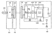
도20은 잉크 용기(1)의 기판(100)의 측면에서 잉크 용기(1)와의 신호 송신을 위한 신호 라인 배선의 구조를 도시한다.FIG. 20 shows the structure of signal line wiring for signal transmission with the
도20에 도시된 바와 같이, 캐리지(205)는 제어 회로(208)를 구비하고, 주 조립체 측 제어 회로(300)로부터 제어 회로(208)로의 신호 라인 배선은 예를 들어 4개의 신호 라인을 포함한다. 특히, 제어 회로(208)로의 신호 라인 배선은 전력 공급을 위한 전압 공급원 신호 라인(VDD)과, 접지 신호 라인(GND)을 포함한다. 또 한, 이는 LED(101)의 켜짐 또는 점멸 프로세스에 관련된 제어 신호(제어 데이터)를 공급하기 위한 신호 라인(DATA)과, 이를 위한 클럭 신호 라인(CLK)을 포함하고, 즉 총 4개의 신호 라인을 포함한다. 이러한 실시예에서, 4개의 신호 라인에서의 설명이 이루어질 것이지만, 본 발명은 그러한 예로 제한되지 않고, 복수의 제어 신호 라인이 경우에 따라 요구될 수 있다. 제어 회로(208)는 주로 DATA 및 CLK 신호의 무선 통신을 위한 고주파 변조 및 복조 회로를 포함하고, 제어 회로(208)는 배선 리드(159)에 의해 루프 안테나(220)와 전기적으로 연결된다. 안테나(220)는 단파장 대역의 전자기 방사선을 발생시키고, 잉크 용기 측의 안테나와 통신한다. 제어 회로(208)는 이러한 실시예에서 캐리지(205) 상에 배치되지만, 안테나 기판(152) 상에 배치될 수 있다.As shown in Fig. 20, the
다른 한편으로, 각각의 잉크 용기(1)의 기판(100)은 주 조립체 측 안테나(220)와의 무선 통신을 위한 안테나(102)를 구비한다. 이는 또한 안테나(102)로부터 수신된 고주파 신호를 처리하고, 안테나(102)로부터 고주파 신호를 송신하기 위한, 신호 처리를 위한 제어기(103)를 구비한다. 또한, 이는 그에 의해 활성화되는 LED(101)를 더 구비한다.On the other hand, the
도21은 제어기 등이 제공되어 있는 기판의 세부를 도시하는 회로도이다. 이러한 도면에 도시된 바와 같이, 제어기(103)는 I/O 제어 회로(103A: I/O CTRL), 메모리 어레이(103B), LED 구동기(103C), 고주파 변조/복조 회로, 및 전압 공급원 회로(103E)를 포함한다. 고주파 변조/복조 회로의 복조 회로는 주 조립체 측 안테나(220)에 의해 수신된 고주파 신호를 복조하여, DATA 및 CLK 신호를 얻는다. 전 압 공급원 회로는 I/O 제어 회로(103A: I/O CTRL), 메모리 어레이(103B), LED 구동기(103C), 및 LED(101)에 전력을 공급하기 위해, 입력된 전자기 방사선으로부터 전압을 발생시킨다. 변조 회로는 메모리 어레이(103B)로부터 주 조립체 측으로 정보를 송신하기 위해, 안테나(102)로부터 전자기 방사선을 발생시키도록 신호를 고주파 전압으로 변조한다.Fig. 21 is a circuit diagram showing details of a substrate on which a controller and the like are provided. As shown in this figure, the
I/O 제어 회로(103A)는 복조된 제어 데이터에 따라, LED(101)에 대한 디스플레이 구동을 제어하고, 데이터의 메모리 어레이(103B)로의 기록 및 그로부터의 판독을 제어한다. 메모리 어레이(103B)는 이러한 실시예에서 EEPROM의 형태이고, 잉크 용기 내의 잉크 잔량, 그 안의 잉크의 컬러 정보에 관련된 정보와 같은 잉크 용기의 개별 정보와, 또한 잉크 용기의 번호, 제작 로트 번호 등과 같은 제조 정보를 저장할 수 있다. 컬러 정보는 잉크 용기 내에 저장된 잉크의 컬러에 대응하는 메모리 어레이(103B)의 소정의 어드레스 내에 기록된다. 예를 들어, 컬러 정보는 도23 및 도24와 관련하여 이하에서 설명될 잉크 용기 구별 정보(개별 정보)로서 사용된다. 이에 의해, 데이터가 메모리 어레이(103B) 내에 기록되고 그로부터 판독될 때, 또는 LED(101)의 활성화 및 불활성화가 특정 잉크 용기에 대해 제어될 때, 잉크 용기를 식별하는 것이 가능하다. 메모리 어레이(103B) 내에 기록되거나 그로부터 판독되는 데이터는 예를 들어, 잉크 잔량을 표시하는 데이터를 포함한다. 이러한 실시예의 잉크 용기는 전술한 바와 같이, 바닥부 내에, 프리즘을 구비하고, 잉크의 잔량이 적어질 때, 이는 프리즘에 의해 광학적으로 검출될 수 있다. 이에 추가하여, 이러한 실시예의 제어 회로(300)는 배출 데이터에 기초하여 각각의 기록 헤드에 대한 배출 횟수를 카운트한다. 잔량 정보는 대응하는 잉크 용기의 메모리 어레이(103B) 내에 기록되고, 정보가 판독된다. 그렇게 함으로써, 메모리 어레이(103B)는 잉크 잔량의 정보를 실시간으로 저장한다. 정보는 또한 정보가 프리즘의 도움으로 제공되므로, 잉크 잔량을 높은 정확성으로 나타낸다. 또한, 이를 장착된 잉크 용기가 새로운 것인지 또는 사용된 다음 재장착된 것인지를 구별하기 위해 사용하는 것이 가능하다.The I /
LED 구동기(103C)는 I/O 제어 회로(103A)로부터 공급된 신호가 높은 수준일 때, 전원 전압을 LED(101)에 인가하여, 이를 발광시키도록 기능한다. 그러므로, I/O 제어 회로(103A)로부터 공급된 신호가 높은 수준일 때, LED(101)는 켜짐 상태이고, 신호가 낮은 수준일 때, LED(101)는 꺼짐 상태이다.The
도22는 도21의 기판의 변형예의 회로도이다. 이러한 변형예는 LED(101)에 전원 전압을 인가하기 위한 구조에 있어서 도21의 예와 다르고, 특히 전압 공급원 전압은 잉크 용기의 기판(100) 내부에 제공된 VDD 전압 공급원 패턴으로부터 공급된다. 보통, 제어기(103)는 반도체 기판 내에 형성되고, 이러한 예에서, 반도체 기판 상에 제공된 연결 접속부는 LED 연결 접속부만을 위한 것이다. 연결 접속부의 개수의 감소는 반도체 기판에 의해 점유되는 면적에 현저하게 영향을 미치고, 이러한 의미에서, 변형예는 반도체 기판의 비용 감소의 측면에서 유리하다.FIG. 22 is a circuit diagram of a modification of the substrate of FIG. 21. This modification is different from the example of Fig. 21 in the structure for applying the power supply voltage to the
도23은 기판의 메모리 어레이(103B)에 대한 데이터 기록 및 판독 작업을 도시하는 시간 선도이다. 도24는 LED(101)의 활성화 및 불활성화를 도시하는 시간 선도이다.Fig. 23 is a time diagram showing data writing and reading operations for the
도23에 도시된 바와 같이, 메모리 어레이(103B) 내로의 기록에 대해, 신호가 주 조립체 측 제어 회로(300)로부터 안테나(220, 102)를 통해 송신된다. 특히, 시작 코드 + 컬러 정보, 제어 코드, 어드레스 코드, 데이터 코드가 나열된 순서대로, 클럭 신호(CLK)와 동기하여 신호 라인(DATA)으로부터 잉크 용기(1)의 제어기(103) 내의 I/O 제어 회로(103A)로 공급된다. 시작 코드 + 컬러 정보 내의 시작 코드 신호는 일련의 데이터 신호의 시작을 표시하고, 컬러 정보 신호는 일련의 데이터 신호가 관련된 특정 잉크 용기를 식별하는데 효과적이다. 여기서, 잉크의 컬러는 Y, M, C 등의 컬러뿐만 아니라 다른 밀도를 갖는 그러한 잉크도 포함한다.As shown in Fig. 23, for writing into the
컬러 정보는 도면에 도시된 바와 같이, 잉크 컬러(K, C, M, Y)들 중 하나에 대응하는 코드를 갖는다. 이를 사용하여, I/O 제어 회로(103A)는 코드에 의해 표시된 컬러 정보와 메모리 어레이(103B) 내에 저장된 컬러 정보를 비교하고, 이들이 동일할 때에만, 데이터 신호가 그 후에 취해진다. 이들이 동일하지 않으면, 후속 데이터 신호는 무시된다. 그러므로, 데이터 신호가 도20에 도시된 공통 신호 라인(DATA)을 통해 주 조립체 측으로부터 모든 잉크 용기로 공통으로 공급되더라도, 데이터가 컬러 정보를 포함하므로, 데이터가 관련된 잉크 용기가 정확하게 식별될 수 있다. 그러므로, 후속 데이터의 기록 및 판독과 LED의 활성화 및 불활성화와 같은, 후속 데이터에 기초한 처리는 식별된 잉크 용기(즉, 올바른 잉크 용기)에 대해서만 실행될 수 있다. 결과적으로, (하나의) 공통 데이터 신호 라인이 LED를 활성화하고 LED를 불활성화하기 위해, 4개의 모든 잉크 용기가 데이터를 기록하기에 충분하고, 따라서 신호 라인의 요구되는 개수를 감소시킨다. 쉽게 이해될 바와 같 이, (하나의) 공통 데이터 신호 라인은 잉크 용기의 개수에 관계없이 충분하다.The color information has a code corresponding to one of the ink colors K, C, M, Y, as shown in the figure. Using this, the I /
도23에 도시된 바와 같이, 이러한 실시예의 제어 모드는 이하에서 설명될 LED의 활성화 및 불활성화를 위한 OFF 및 ON 코드와, 메모리 어레이로부터의 판독 및 그로의 기록을 위한 READ 및 WRITE 코드를 포함한다. 기록 작업 시에, WRITE 코드는 잉크 용기를 식별하기 위한 컬러 정보 코드에 뒤따른다. 다음의 코드, 즉 어드레스 코드는 데이터가 기록되는 메모리 어레이 내의 어드레스를 표시하고, 최종 코드, 즉 데이터 코드는 기록되는 정보의 내용을 표시한다.As shown in Fig. 23, the control mode of this embodiment includes OFF and ON codes for activating and deactivating LEDs to be described below, and READ and WRITE codes for reading from and writing to a memory array. . In the recording operation, the WRITE code follows the color information code for identifying the ink container. The next code, namely address code, indicates an address in the memory array in which data is written, and the final code, namely data code, indicates the content of the information to be written.
제어 코드에 의해 표시되는 내용은 전술한 예로 제한되지 않고, 예를 들어, 검증 명령 및/또는 연속 판독 명령을 위한 제어 코드가 추가될 수 있다.The content indicated by the control code is not limited to the example described above, and for example, a control code for a verify command and / or a continuous read command may be added.
판독 작업에 대해, 데이터 신호의 구조는 기록 작업의 경우에서와 동일하다. 시작 코드 + 컬러 정보의 코드는 기록 작업의 경우와 유사하게, 모든 잉크 용기의 I/O 제어 회로(103A)에 의해 취해진다. 후속 데이터 신호는 동일한 컬러 정보를 갖는 잉크 용기의 I/O 제어 회로(103A)에 의해서만 취해진다. 다른 점은 어드레스가 어드레스 코드에 의해 지정된 후에 판독 데이터가 제1 클럭(도23의 13번째 클럭)의 발생과 동기하여 출력되는 것이다. 따라서, I/O 제어 회로(103A)는 잉크 용기의 데이터 신호가 공통된 (하나의) 데이터 신호 라인과 통신하더라도, 판독 신호의 다른 입력 신호와의 간섭을 방지하기 위한 제어를 실행한다.For the read operation, the structure of the data signal is the same as in the case of the write operation. The code of the start code + color information is taken by the I /
도24에 도시된 바와 같이, LED(101)의 활성화(켜짐) 및 불활성화(꺼짐)에 대해, 시작 코드 + 컬러 정보의 데이터 신호는 위와 유사하게, 주 조립체 측으로부터 신호 라인(DATA)을 통해 I/O 제어 회로(103A)로 최초로 송신된다. 전술한 바와 같 이, 올바른 잉크 용기가 컬러 정보에 기초하여 식별되고, 이후에 공급되는 제어 코드에 의한 LED(101)의 활성화 및 불활성화는 식별된 잉크 용기에 대해서만 실행된다. 활성화 및 불활성화를 위한 제어 코드는 도23과 관련하여 전술한 바와 같이, 각각 LED(101)를 활성화 및 불활성화하는데 효과적인 ON 코드 및 OFF 코드 중 하나를 포함한다. 즉, 제어 코드가 ON을 표시할 때, I/O 제어 회로(103A)는 도22와 관련하여 전술한 바와 같이, ON 신호를 LED 구동기(103C)로 출력하고, 출력 상태가 그 후에 계속하여 유지된다. 대조적으로, 제어 코드가 OFF를 표시할 때, I/O 제어 회로(103A)는 OFF 신호를 LED 구동기(103C)로 출력하고, 출력 상태가 그 후에 계속하여 유지된다. LED(101)의 활성화 또는 불활성화를 위한 실제 타이밍은 각각의 데이터 신호에 대해 클럭(CLK)의 7번째 클럭 후이다.As shown in Fig. 24, for activation (on) and deactivation (off) of the
이러한 도면의 예에서, 가장 좌측의 데이터 신호가 지정하는 검정(K) 잉크 용기가 최초로 식별되고, 그 다음 검정 잉크(K) 용기의 LED(101)가 켜진다. 그 다음, 제2 데이터 신호의 컬러 정보는 마젠타 잉크(M)를 표시하고, 제어 코드는 활성화를 표시하고, 그러므로 잉크(K) 용기의 LED(101)가 ON 상태로 유지되는 동안, 잉크(M) 용기의 LED(101)가 켜진다. 제3 데이터 신호의 제어 코드는 불활성화의 지시를 의미하고, 잉크(K) 용기의 LED(101)만이 불활성화된다.In the example of this figure, the black (K) ink container designated by the leftmost data signal is first identified, and then the
상기 설명으로부터 이해될 바와 같이, LED의 점멸 제어는 식별된 잉크 용기에 대해 교대로 반복되는 활성화 및 불활성화 제어 코드를 송신하는 주 조립체 측의 제어 회로(300)에 의해 달성된다. 점멸의 주기는 교대하는 제어 코드의 주기를 선택함으로써 결정될 수 있다.As will be appreciated from the above description, the blink control of the LED is achieved by the
2.3 제어 프로세스(도25 - 도31):2.3 Control Process (Figures 25-31):
도25는 본 발명의 실시예에 따른 잉크 용기의 장착 및 탈착에 관련된 제어 프로세스를 도시하는 흐름도이고, 특히 주 조립체 측에 제공된 제어 회로(300)에 의한 각각의 잉크 용기(1)의 LED(101)에 대한 활성화 및 불활성화 제어를 도시한다.Fig. 25 is a flowchart showing a control process related to mounting and detaching of an ink container according to an embodiment of the present invention, in particular the
도25에 도시된 프로세스는 소정의 센서에 의해 검출되는 프린터(201)의 주 조립체 커버를 개방하는 사용자에 응답하여 시작된다. 프로세스가 시작될 때, 잉크 용기는 단계(S101)에 의해 장착 또는 탈착된다.The process shown in Fig. 25 starts in response to a user opening the main assembly cover of the
도26은 도25의 잉크 용기의 장착 및 탈착 프로세스의 흐름도이다. 도면에 도시된 바와 같이, 장착 또는 탈착 프로세스에서, 캐리지(205)가 단계(S201)에서 이동하고, 캐리지(205) 상에 보유된 잉크 용기의 상태 정보(그의 개별 정보)가 얻어진다. 여기서 얻어지는 상태 정보는 잉크 용기 고유의 숫자와 함께 메모리 어레이(103B)로부터 판독된 잉크 잔량 등이다. 단계(S202)에서, 캐리지(205)가 도18과 관련하여 설명된 잉크 용기 교환 위치에 도달했는지에 관한 구별이 이루어진다.FIG. 26 is a flow chart of the mounting and demounting process of the ink container of FIG. As shown in the figure, in the mounting or detaching process, the
구별의 결과가 긍정이면, 단계(S203)가 잉크 용기 장착 확인 제어를 위해 실행된다.If the result of the discrimination is affirmative, step S203 is executed for ink container mounting confirmation control.
도27은 도26의 장착 확인 제어를 상세하게 도시되는 흐름도이다. 먼저, 단계(S301)에서, 캐리지(205) 상에 보유된 잉크 용기의 개수를 표시하는 파라미터(N)가 설정되고, 잉크 용기의 개수에 대응하여 LED의 발광 확인을 위한 플래그(F(k))가 초기화된다. 이러한 실시예에서, N은 잉크 용기의 개수가 4개(K, C, M, Y)이므 로, 4로 설정된다. 그 다음, 4개의 플래그(F(k), k = 1 - 4)가 준비되고, 이들은 모두 0으로 초기화된다.FIG. 27 is a flowchart showing the mounting confirmation control of FIG. 26 in detail. First, in step S301, a parameter N indicating the number of ink containers held on the
단계(S302)에서, 잉크 용기에 대한 장착 구별의 순서에 관련된 플래그의 변수(An)가 "1"로 설정되고, 단계(S303)에서, 장착 확인 제어는 A번째 잉크 용기에 대해 실행된다. 이러한 제어에서, 사용자가 기록 헤드 유닛(105)의 홀더(150) 내의 정확한 위치에 잉크 용기를 설치함으로써, 홀더(150)의 안테나 기판(152)과 잉크 용기의 안테나(102) 사이의 무선 통신이 가능해진다. 이에 의해, 주 조립체 측의 제어 회로(300)는 전술한 바와 같이, 컬러 정보(잉크 용기에 대한 개별 정보)에 기초하여 잉크 용기를 식별하고, 식별된 용기의 메모리 어레이(103B) 내에 저장된 컬러 정보가 연속하여 판독된다. 식별을 위한 컬러 정보는 이미 판독된 것에 대해 사용되지 않는다. 이러한 제어 프로세스에서, 판독된 컬러 정보가 이러한 프로세스의 시작 후에 이미 판독된 컬러 정보와 다른지에 관한 구별이 또한 이루어진다.In step S302, the variable An of the flag related to the order of mounting discrimination to the ink container is set to " 1 ", and in step S303, the mounting confirmation control is executed for the A-th ink container. In this control, by the user installing the ink container at the correct position in the
단계(S304)에서, 컬러 정보가 판독될 수 있었고, 컬러 정보가 이미 판독된 정보와 다르면, 컬러 정보의 잉크 용기가 A번째 잉크 용기로서 장착되었다고 구별된다. 그렇지 않으면, A번째 잉크 용기가 장착되지 않았다고 구별된다. 여기서, "A번째"는 잉크 용기의 구별 순서만을 나타내고, 잉크 용기의 장착 위치를 표시하는 순서는 나타내지 않는다. A번째 잉크 용기가 정확하게 장착된 것으로 구별될 때, 플래그(F(A): 준비된 플래그(F(k), k = 1 - 4) 중에서 k = A를 만족시키는 플래그)가 단계(S305)에서 "1"로 설정된다. 그 다음, 도24와 관련하여 전술한 바와 같이, 대응하는 컬러 정보를 갖는 잉크 용기(1)의 LED(101)가 켜진다. 잉크 용기 가 장착되지 않았다고 구별될 때, 플래그(F(A))는 단계(S311)에서 "0"으로 설정된다.In step S304, if the color information could be read and the color information is different from the already read information, it is discriminated that the ink container of the color information is mounted as the A-th ink container. Otherwise, it is discriminated that the A-th ink container is not mounted. Here, "Ath" shows only the distinguishing order of the ink container, and does not show the order which shows the mounting position of the ink container. When it is distinguished that the A-th ink container is correctly loaded, the flag F (A): a flag satisfying k = A among the prepared flags F (k), k = 1-4) is displayed in step S305. Is set to 1 ". Then, as described above with reference to Fig. 24, the
그 다음, 단계(S306)에서, 변수(A)는 1만큼 증가되고, 단계(S307)에서, 변수(A)가 단계(S301)에서 설정된 N(이러한 실시예에서, N = 4)보다 더 큰지에 관한 구별이 이루어진다. 변수(A)가 N보다 더 크지 않으면, 단계(S303) 이후의 프로세스가 반복된다. 그가 N보다 더 크다고 구별되면, 이러한 사실은 장착 확인 제어가 모든 4개의 잉크 용기에 대해 완료되었다는 것을 의미한다. 그 다음, 단계(S308)에서, 센서의 출력에 기초하여 주 조립체 커버(201)가 개방 위치에 있는지에 관한 구별이 이루어진다. 주 조립체 커버가 폐쇄 위치에 있을 때, 잉크 용기들 중 하나 또는 일부가 장착되지 않거나 적절하게 장착되지 않더라도, 사용자가 커버를 폐쇄했을 가능성이 있으므로, 비정상 상태가 단계(S312)에서 도26의 처리 루틴으로 복귀된다. 그 다음, 이러한 프로세스 작동은 완료된다.Then, in step S306, the variable A is increased by one, and in step S307, whether the variable A is greater than N (in this embodiment, N = 4) set in step S301. A distinction is made about. If the variable A is not greater than N, the process after step S303 is repeated. If he is distinguished as being larger than N, this means that the mounting confirmation control has been completed for all four ink containers. Then, in step S308, a distinction is made as to whether the
대조적으로, 주 조립체 커버(201)가 단계(S308)에서 개방된 것으로 구별될 때, 4개의 모든 플래그(F(k), k = 1 - 4)가 "1"인지, 즉 LED(101)가 모두 켜져 있는지에 관한 구별이 이루어진다. LED(101)들 중 적어도 하나가 켜지지 않았다고 구별되면, 단계(S302) 이후의 프로세스가 반복된다. 사용자가 LED 또는 LED(101)들이 켜지지 않은 잉크 용기 또는 잉크 용기들을 장착하거나 정확하게 재장착할 때까지, 잉크 용기 또는 용기들의 LED 또는 LED들이 켜지고, 프로세스 작동은 반복된다.In contrast, when the
모든 LED가 켜진 것으로 구별될 때, 정상 종료 작동이 단계(S310)에서 수행 되고, 이러한 프로세스 작동은 완료된다. 그 다음, 프로세스는 도26에 도시된 처리 루틴으로 복귀한다. 도28의 (a)는 모든 잉크 용기가 각각 정확한 위치에 정확하게 장착되고 LED가 모두 켜진 상태를 도시한다.When all the LEDs are distinguished to be on, a normal termination operation is performed in step S310, and this process operation is completed. Then, the process returns to the processing routine shown in FIG. Figure 28 (a) shows a state in which all the ink containers are each correctly mounted at the correct positions and all the LEDs are turned on.
다시 도26을 참조하면, 잉크 용기 장착 확인 제어(단계 S203)가 전술한 방식으로 실행된 후에, 단계(S204)에서, 제어가 정상적으로 완료되었는지, 즉 잉크 용기가 적절하게 장착되었는지에 관한 구별이 이루어진다. 장착이 정상적인 것으로 구별되면, 작동부(213) 내의 표시 장치(도17 및 도18)는 단계(S205)에서 예를 들어 녹색으로 발광되고, 정상 종료가 단계(S206)에서 실행되고, 작동은 도25에 도시된 처리 루틴으로 복귀한다. 비정상 장착이 구별될 때, 작동부(213) 내의 표시 장치는 단계(S207)에서 예를 들어 황색으로 점멸되고, 비정상 종료 프로세스가 수행되고, 그 다음 작동은 도25에 도시된 처리 루틴으로 복귀한다. 프린터가 프린터를 제어하는 호스트 PC와 연결되어 있을 때, 장착 비정상 표시는 또한 동시에 PC의 디스플레이 상에서 실행된다.Referring again to Fig. 26, after the ink container mounting confirmation control (step S203) is executed in the above-described manner, in step S204, a distinction is made as to whether the control is normally completed, that is, whether the ink container is properly mounted. . If the mounting is discriminated as normal, the display device (Figs. 17 and 18) in the
도25에서, 단계(S101)의 잉크 용기 장착 및 탈착 프로세스가 완료되었을 때, 단계(S102)에서, 장착 및 탈착 프로세스가 적절하게 완료되었는지에 관한 구별이 이루어진다. 비정상이 구별되면, 프로세스 작동은 사용자가 주 조립체 커버(201)를 개방하기를 기다리고, 커버(201)의 개방에 응답하여, 단계(S101)의 프로세스가 시작되어, 도26과 관련하여 설명된 프로세스가 반복된다.In Fig. 25, when the ink container mounting and demounting process of step S101 is completed, in step S102, a distinction is made as to whether the mounting and demounting process is properly completed. If an abnormality is distinguished, the process operation waits for the user to open the
적절한 장착 또는 탈착 프로세스가 단계(S102)에서 구별될 때, 프로세스는 단계(S103)에서 사용자가 주 조립체 커버(201)를 폐쇄하기를 기다리고, 단계(S104) 에서 커버(201)가 폐쇄되었는지에 관한 구별이 이루어진다. 구별의 결과가 긍정이면, 작동은 단계(S105)의 광 검증 프로세스로 진행한다. 이러한 경우에, 주 조립체 커버(201)의 폐쇄가 도28의 (b)에 의해 도시된 바와 같이 검출되면, 캐리지(205)는 광 검증을 위한 위치로 이동하고, 잉크 용기의 LED(101)는 불활성화된다.When an appropriate mounting or demounting process is distinguished in step S102, the process waits for the user to close the
광 검증 프로세스는 적절하게 장착된 잉크 용기들이 각각 정확한 위치에 장착되었는지를 구별하도록 의도된다. 이러한 실시예에서, 잉크 용기의 구조는 그의 구성이 잉크 용기가 틀린 위치에 장착되는 것을 방지할 목적으로 내부에 수납된 잉크의 컬러에 의존하여 고유하게 만들어지도록 되어 있지 않다. 이는 잉크 용기 본체의 간단한 제조를 위한 것이다. 그러므로, 잉크 용기가 틀린 위치에 장착될 가능성이 있다. 그러므로, 광 검증 프로세스는 그러한 틀린 장착을 검출하고 이를 사용자에게 통보하는데 효과적이다. 이에 의해, 잉크의 컬러에 의존하여 잉크 용기들의 구성을 서로 다르게 만드는 것이 요구되지 않으므로, 잉크 용기 제조의 효율 및 저비용이 달성된다.The light verification process is intended to distinguish whether or not properly mounted ink containers are each mounted at the correct position. In this embodiment, the structure of the ink container is not intended to be made uniquely depending on the color of the ink contained therein for the purpose of preventing the ink container from being mounted at the wrong position. This is for simple manufacture of the ink container body. Therefore, there is a possibility that the ink container is mounted at the wrong position. Therefore, the light verification process is effective in detecting such false mounting and informing the user of this. Thereby, since it is not required to make the configurations of the ink containers different depending on the color of the ink, efficiency and low cost of ink container manufacturing are achieved.
도29의 (a) - (d)는 광 검증 프로세스를 도시하고, 도30의 (a) - (d) 또한 광 검증 프로세스를 도시한다.Figures 29 (a)-(d) show the light verification process, and Figures 30 (a)-(d) also show the light verification process.
도29의 (a)에 의해 도시된 바와 같이, 이동 가능한 캐리지(205)는 먼저 제1 수광부(210)를 향해 도면에서 좌측으로부터 우측으로 이동하기 시작한다. 황색 잉크 용기에 대한 위치에 위치된 잉크 용기가 제1 수광부(210)에 대향될 때, 황색 잉크 용기의 LED(101)를 활성화하기 위한 신호가 도24와 관련하여 설명된 제어에 의 해 출력되어, 그를 켜고 켜짐 상태를 소정의 기간 동안 유지한다. 잉크 용기가 정확한 위치에 위치될 때, 제1 수광부(210)가 LED(101)로부터 광을 수신하여, 제어 회로(300)는 잉크 용기(1Y)가 정확한 위치에 장착되었다고 구별한다.As shown by Fig. 29A, the
유사하게, 캐리지(205)를 이동시키는 동안, 도29의 (b)에 의해 도시된 바와 같이, 마젠타 잉크 용기에 대한 위치에 위치된 잉크 용기가 제1 수광부(210)에 대향될 때, 마젠타 잉크 용기의 LED(101)를 활성화하기 위한 신호가 출력되어, 그를 켜고 켜짐 상태를 소정의 기간 동안 유지한다. 도면에 도시된 예에서, 잉크 용기(1M)는 정확한 위치에 장착되어, 제1 수광부(210)가 LED로부터 광을 수신한다. 도29의 (b) - (d)에 의해 도시된 바와 같이, 광은 구별 위치를 변화시키면서, 순차적으로 방출된다. 이러한 도면에서, 모든 잉크 용기가 정확한 위치에 장착된다.Similarly, while moving the
대조적으로, 시안 잉크 용기(1C)가 도30의 (b)에 의해 도시된 바와 같이, 마젠타 잉크 용기(1M)에 대한 위치에 잘못 장착되면, 제1 수광부(210)에 대향하는 잉크 용기(1C)의 LED(101)는 활성화되지 않지만, 다른 위치에 장착된 잉크 용기(1M)는 켜진다. 결과적으로, 제1 수광부(210)가 소정의 타이밍에서 광을 수신하지 않아서, 제어 회로(300)는 장착 위치가 잉크 용기(1M: 올바른 용기)가 아닌 잉크 용기를 가졌다고 구별한다. 대응하여, 마젠타 잉크 용기(1M)가 도30의 (c)에 의해 도시된 바와 같이, 시안 잉크 용기(1C)에 대한 위치에 잘못 장착되면, 제1 수광부(210)에 대향하는 잉크 용기(1M)의 LED(101)는 활성화되지 않지만, 다른 위치에 장착된 잉크 용기(1C)는 켜진다.In contrast, when the
이러한 방식으로, 전술한 제어 회로(300)에서의 광 검증 프로세스는 정확한 위치에 장착되지 않은 잉크 용기 또는 잉크 용기들을 식별하는데 효과적이다. 장착 위치가 그에 장착된 정확한 잉크 용기를 갖지 않으면, 거기에 잘못 장착된 잉크 용기의 컬러는 다른 3개의 컬러 잉크 용기의 LED를 순차적으로 활성화함으로써 식별될 수 있다.In this way, the light verification process in the
도25에서, 단계(S105)의 광 검증 프로세스 후에, 단계(S106)에서 광 검증 프로세스가 적절하게 완료되었는지에 관한 구별이 이루어진다. 광 검증의 적절한 완료가 구별될 때, 작동부(213) 내의 표시 장치는 단계(S107)에서 예를 들어 녹색으로 켜지고, 프로세스가 종료된다. 다른 한편으로, 종료가 비정상인 것으로 구별되면, 작동부(213) 내의 표시 장치는 단계(S109)에서 황색으로 점멸되고, 정확한 위치에 장착되지 않아서 단계(S105)에서 식별된 잉크 용기의 LED(101)가 단계(S105)에서 점멸되거나 켜진다. 이러한 방식으로, 사용자가 주 조립체 커버(201)를 개방할 때, 사용자는 정확한 위치에 장착되지 않은 잉크 용기를 통보받아서, 사용자는 그를 정확한 위치에 재장착하도록 지시받는다.In Fig. 25, after the light verification process in step S105, a distinction is made as to whether the light verification process is properly completed in step S106. When the proper completion of the light verification is distinguished, the display device in the
도31은 본 발명의 실시예에 따른 기록 프로세스를 도시하는 흐름도이다. 이러한 프로세스에서, 잉크 잔량이 먼저 단계(S401)에서 점검된다. 이러한 프로세스에서, 인쇄량이 인쇄가 실행될 작업의 인쇄 데이터로부터 결정되고, 잔량이 충분한지를 점검하기 위해 결정량과 잉크 용기의 잔량 사이의 비교가 이루어진다 (확인 프로세스). 이러한 프로세스에서, 잉크 잔량은 카운팅에 기초하여 제어 회로(300)에 의해 검출된 양일 수 있다.Fig. 31 is a flowchart showing a recording process according to the embodiment of the present invention. In this process, the ink remaining amount is first checked in step S401. In this process, the printing amount is determined from the print data of the job to be printed, and a comparison is made between the determination amount and the remaining amount of the ink container to check whether the remaining amount is sufficient (confirmation process). In this process, the ink remaining amount may be the amount detected by the
단계(S402)에서, 확인 프로세스에 기초하여, 잉크 잔량이 의도된 인쇄에 대 해 충분한지에 관한 구별이 이루어진다. 다른 한편으로, 단계(S402)에서의 구별의 결과가 잉크의 부족을 표시하면, 작동부(213)의 표시 장치는 단계(S405)에서 황색으로 점멸되고, 단계(S406)에서, 불충분한 양의 잉크를 수납한 잉크 용기(1)의 LED(101)가 점멸되거나 켜진다 (비정상 종료). 기록 장치가 기록 장치를 제어하는 호스트 PC와 연결되어 있을 때, 잉크 잔량은 동시에 PC의 디스플레이 상에 표시될 수 있다.In step S402, based on the confirmation process, a distinction is made as to whether the ink remaining amount is sufficient for the intended printing. On the other hand, if the result of the discrimination in step S402 indicates the lack of ink, the display device of the
3. 기타 실시예(도32 - 도54):3. Other Examples (Figures 32-54):
위에서 설명된 제1 실시예에서, 잉크 용기 후면 상에 제공된 제1 결합부(5)는 홀더의 후면에 제공된 제1 로킹부(155) 내로 삽입되고, 잉크 용기(1)는 잉크 용기 전면을 아래로 밀면서, 삽입된 부분인 회전 피벗에 대해 회전된다. 그러한 구조가 채용될 때, 기판(100)의 양호한 위치는 전술한 바와 같이, 회전 피벗으로부터 먼 전면이고, 제1 수광부(210)와, 광을 제1 수광부(210) 및 사용자의 눈을 향해 지향시키기 위한 제1 발광부(101)는 따라서 기판(100)과 일체이다.In the first embodiment described above, the first engaging
그러나, 몇몇 경우에, 기판에 의해 선호되는 위치와 발광부에 의해 요구되는 위치는 잉크 용기의 구조 및/또는 그의 장착부에 따라 서로 다르다. 그러한 경우에, 기판 및 발광부는 적절한 위치에 배치될 수 있다. 그러므로, 이들은 반드시 서로 일체는 아니다.However, in some cases, the position preferred by the substrate and the position required by the light emitting portion differ from each other depending on the structure of the ink container and / or its mounting portion. In such a case, the substrate and the light emitting portion may be disposed at appropriate positions. Therefore, they are not necessarily one another.
도32의 (a) - (c)는 본 발명의 다른 실시예에 따른 잉크 용기 및 그의 장착부의 구조를 도시한다.Figures 32 (a)-(c) show the structure of the ink container and its mounting portion according to another embodiment of the present invention.
도32의 (a)에 의해 도시된 바와 같이, 본 발명의 이러한 실시예의 잉크 용 기(501)는 전면에 인접한 상부면 상에서, 후방 상부에서 패드(602)를 갖는 LED와 같은 발광부(601)를 갖는 기판(600)을 구비한다. 발광부(601)가 활성화될 때, 광은 전면을 향해 방출된다. 수광부(620)가 캐리지의 스캐닝 범위의 일 단부에 인접하여 도면에서 좌측으로 지향되는 광을 수신하기 위한 위치에 배치된다. 캐리지가 그러한 위치에 왔을 때, 발광부(601)는 기록 장치 측이 수광부에 의해 수신된 광의 내용으로부터 잉크 용기(501)에 관련된 소정의 정보를 얻을 수 있도록 제어된다. 캐리지가 예를 들어 스캐닝 범위의 중심부에 있을 때, 발광부(601)가 제어되고, 이에 의해 사용자는 발광 상태를 볼 수 있어서, 잉크 용기(501)에 관련된 소정의 정보가 사용자에 의해 쉽게 인식될 수 있다.As shown by Fig. 32 (a), the
도32의 (c)에 의해 도시된 바와 같이, 기록 헤드 유닛(605)은 복수(도면의 예에서, 2개)의 잉크 용기를 탈착 가능하게 유지하기 위한 홀더(650)와, 그의 바닥면에 제공된 기록 헤드(605')를 포함한다. 홀더(650) 내에 잉크 용기(501)를 장착함으로써, 홀더의 내측 바닥부 내에 위치된 기록 헤드 측의 잉크 도입 개방부(607)가 잉크 용기의 바닥부 내에 위치된 잉크 공급 포트(507)와 연결되어, 잉크 유체 연통 경로가 이들 사이에 확립된다. 홀더(650)는 그의 후면 상에서, 전면의 결합부(655: 회전 중심)와의 완전한 장착 위치에 잉크 용기(501)를 로킹시키기 위한 로킹부(656)를 구비한다. 로킹부(656)에 인접하여, 기판(600) 안테나(602)와의 통신을 위한 안테나(652)가 제공된다.As shown by Fig. 32 (c), the
잉크 용기(501)가 기록 헤드 유닛(605)에 장착될 때, 잉크 용기(501)는 홀더(650)의 전면에서 취급된다. 도32의 (b)에 의해 도시된 바와 같이, 사용자는 잉 크 용기 후면의 하부 모서리 부분을 홀더(650)의 후면에 대해 가압하여, 잉크 용기 전면을 홀더(650)의 결합부(655)와 결합시킨다. 이러한 상태에서, 잉크 용기(501)의 전면의 상부는 후면을 향해 가압되고, 이에 의해 잉크 용기(501)는 결합부(655)에 대해 화살표에 의해 표시된 방향으로 회전하면서 홀더 내에 장착된다. 도32의 (a) 및 (c)에서, 완전히 장착된 잉크 용기(501)가 도시되어 있고, 여기서 잉크 공급 포트(507)와 잉크 도입 개방부(607)가 서로 연결되고, 안테나(602)와 안테나(652)가 서로 근접한다.When the
홀더(650)의 결합부(655) 및 로킹부(656)의 구조와, 잉크 용기(501) 측의 대응하는 구조는 당업자에 의해 적절하게 결정될 수 있다. 도면에 도시된 예에서, 기판(600)은 잉크 용기(501)의 상부 표면 상에 제공되어, 상부 표면과 평행하게 연장되지만, 이는 제한적이지 않고, 제1 실시예에서와 같이 경사질 수 있다. 또한, 홀더(650) 및 그에 관련된 구조 부재들은 반드시 헤드 유닛 내에 제공되지는 않는다.The structures of the engaging
도33은 도32의 구조의 변형예를 도시하고, 서로 일체인 잉크 용기(501) 및 기록 헤드(605')를 각각 포함하는 2개의 기록 헤드 유닛(액체 수납 카트리지)을 도시한다. 이러한 실시예에서, 유닛들 중 하나는 검정 잉크를 위한 카트리지이고, 다른 하나는 황색, 마젠타, 및 시안 잉크를 위한 카트리지이다.Fig. 33 shows a modification of the structure of Fig. 32, and shows two recording head units (liquid storage cartridges) each including an
홀더(650)는 그러한 구조에 대응하는 유사한 구조를 구비할 수 있다. 이러한 실시예에서, 전면 상에 배치된 발광부(601)를 위한 제어 회로는 헤드 유닛 상의 적절한 위치에 제공될 수 있다. 예를 들어, 제어 회로는 일체형 기록 헤드(605') 를 갖는 구동 회로 기판 상에 제공되고, 배선은 발광부(601)로 연장된다. 그러한 경우에, 기록 헤드(605')를 위한 구동 회로 및 발광부(601)를 위한 제어 회로는 도시되지 않은 전기 접속부를 통해 캐리지 상의 전기 접속부와 연결된다.
도34는 주 조립체 커버가 개방 상태로 도시된, 본 발명의 상기 다른 실시예에 따른 잉크 용기가 사용될 수 있는 프린터의 사시도이다. 도17 및 도18에 도시된 실시예에서와 동일한 도면 부호가 이러한 실시예에서 대응하는 기능을 갖는 요소에 할당되고, 그의 상세한 설명은 간단하게 하기 위해 생략된다.Figure 34 is a perspective view of a printer in which an ink container according to the other embodiment of the present invention can be used, with the main assembly cover shown in an open state. The same reference numerals as in the embodiment shown in Figs. 17 and 18 are assigned to elements having corresponding functions in this embodiment, and detailed description thereof is omitted for simplicity.
도34에 도시된 바와 같이, 검정 잉크를 수납하는 잉크 용기(501K)와, 시안, 마젠타, 및 황색 잉크를 분리하여 수납하는 일체형 수용 챔버를 갖는 잉크 용기(501CMY)가 캐리지(205) 상의 기록 헤드 유닛(605)의 홀더 내에 장착된다. 각각의 잉크 용기에서, 전술한 바와 같이, LED(601)가 기판으로부터 분리된 부재로서 제공되고, 사용자는 잉크 용기가 교환 위치에 장착되었을 때, 전면의 LED(601)를 볼 수 있다. LED의 위치에 대응하여, 수광부(210)가 캐리지(205)의 이동 범위의 단부들 중 하나에 이웃하여 제공된다.As shown in Fig. 34, an
도35의 (a) 및 (b)는 본 발명의 추가의 실시예에 따른 잉크 용기의 개략적인 측면도 및 개략적인 정면도이고, 제1 실시예는 기판 및 발광부를 상이한 위치에 위치시킴으로써 변형되었다.35A and 35B are schematic side and schematic front views of an ink container according to a further embodiment of the present invention, and the first embodiment has been modified by placing the substrate and the light emitting portion at different positions.
이러한 실시예에서, LED와 같은 발광부(101)를 각각 갖는 기판(100-2)은 잉크 용기 전면의 상부 상에 제공된다. 상기 실시예와 유사하게, 기판(100)은 경사진 표면 부분 상에 제공되고, 이는 그렇게 하는 것이 캐리지 측에 제공된 안테나 기판(152)과의 만족스러운 통신, 잉크로부터의 보호의 관점에서 양호하기 때문이고, 기판(100)은 배선부(159-2)에 의해 기판(100-2) 또는 발광부(101)와 연결되어, 전기 신호가 그들 사이에서 송신될 수 있다. 잉크 용기 케이싱을 따라 배선부(159-2)를 연장시키기 위해 지지 부재(3)의 기부 내에 형성된 구멍이 3H에 의해 표시되어 있다.In this embodiment, the substrates 100-2 each having
이러한 실시예에서, 발광부(101)가 활성화될 때, 광은 전면을 향해 지향된다. 수광부(210)가 캐리지의 스캐닝 범위의 일 단부에 인접하여 도면에서 우측으로 지향되는 광을 수신하기 위한 위치에 배치되고, 캐리지가 그러한 위치와 대면할 때, 발광부(101)의 발광이 제어된다. 기록 장치 측은 수광부에 의해 수신된 광의 내용으로부터 잉크 용기(1)에 관련된 소정의 정보를 얻을 수 있다. 그렇게 함으로써, 기록 장치 측은 수광부에 의해 수신된 광의 내용으로부터 잉크 용기(1)에 관련된 소정의 정보를 얻을 수 있다. 캐리지가 예를 들어 스캐닝 범위의 중심부에 있을 때, 발광부(101)가 제어되고, 이에 의해 사용자는 발광 상태를 더욱 쉽게 볼 수 있어서, 잉크 용기(1)에 관련된 소정의 정보가 사용자에 의해 인식될 수 있다.In this embodiment, when the
도36의 (a) 및 (b)는 도35의 변형된 실시예에 따른 잉크 용기의 개략적인 측면도 및 개략적인 정면도이다. 이러한 실시예에서, 발광부(101) 및 이를 지지하는 기판(100-2)은 잉크 용기 전면에서 작동부(3M)의 배면 상에 제공되고, 작동부(3M)는 사용자에 의해 조작되는 부분이다. 이러한 실시예의 기능 및 유리한 효과는 상기 실시예와 동일하다. 실시예에 따르면, 캐리지가 예를 들어 스캐닝 범위의 중심부에 위치될 때, 발광부(101)가 활성화되고, 그러므로 지지 부재(3)의 작동부(3M) 또한 조명되어, 사용자는 요구되는 조작, 예를 들어 잉크 용기의 교환을 직관적으로 이해할 수 있다. 작동부(3M)는 작동부(3M)의 조명 상태의 인식을 용이하게 하기 위해 적절한 광량을 투과 또는 산란시키기 위한 부분을 구비할 수 있다.36A and 36B are schematic side and schematic front views of the ink container according to the modified embodiment of FIG. In this embodiment, the
도37은 도35의 구조의 변형예의 개략적인 측면도이다. 이러한 실시예에서, 발광부(101)를 갖는 기판(100-2)은 지지 부재(3)의 작동부(3M)의 전면 상에 배치된다. 기판(100), 기판(100-2), 및 발광부(101)는 지지 부재(3)를 따라 연장되는 배선부(159-2)에 의해 지지 부재(3)의 기부 내에 형성된 구멍(3H)을 통해 서로 연결된다. 이러한 예에 따르면, 도36에서와 동일한 유리한 효과가 제공될 수 있다.FIG. 37 is a schematic side view of a modification of the structure of FIG. 35; FIG. In this embodiment, the substrate 100-2 having the
도35 - 도37에 도시된 구조에서, 가요성 인쇄 케이블(FPC)이 사용될 수 있고, 이에 의해 기판(100), 배선부(159-2), 및 기판(100-2)은 하나의 일체형 부재일 수 있다.In the structure shown in Figs. 35-37, a flexible printed cable (FPC) can be used, whereby the
상기 실시예에서, 액체 공급 시스템은 일정량의 배출되는 잉크가 주 스캐닝 방향으로 왕복하는 기록 헤드에 분리되어 장착된 잉크 용기의 사용에 의해 인쇄 헤드에 실질적으로 연속적으로 공급되는, 소위 연속 공급형이다. 특히, 상기 실시예의 설명은 캐리지 등에서 왕복하는 기록 헤드에 탈착식으로 장착될 수 있는 잉크 용기에 대해 이루어졌다. 그러나, 본 발명은 잉크 용기가 기록 헤드에 일체형으로 고정된, 다른 액체 공급 시스템에 적용될 수 있다. 그러한 시스템에서도, 장착 위치가 정확하지 않으면, 기록 헤드가 다른 컬러에 대한 데이터를 수신하거나, 상이한 컬러 잉크 배출의 순서가 소정의 순서와 다르고, 그 결과 기록 품질이 악화된다.In this embodiment, the liquid supply system is a so-called continuous supply type in which a certain amount of discharged ink is supplied substantially continuously to the print head by use of an ink container separately mounted to the recording head reciprocating in the main scanning direction. In particular, the description of the above embodiment has been made with respect to an ink container that can be detachably mounted to a recording head reciprocating in a carriage or the like. However, the present invention can be applied to other liquid supply systems in which the ink container is fixedly fixed to the recording head. Even in such a system, if the mounting position is not correct, the recording head receives data for different colors, or the order of different color ink ejections differs from the predetermined order, resulting in deterioration of recording quality.
본 발명은 잉크 용기가 기록 헤드로부터 분리되어, 기록 장치 내의 고정된 위치에 제공되고, 고정식 잉크 용기와 관련 기록 헤드가 기록 헤드에 잉크를 공급하기 위한 튜브에 의해 연결되는, 다른 연속 공급형에 적용될 수 있다. 잉크 용기와 기록 헤드 사이에서 유체 연통하는 중간 용기가 기록 헤드 또는 캐리지 상에 보유될 수 있다.The present invention is applicable to another continuous supply type, in which the ink container is separated from the recording head, is provided at a fixed position in the recording apparatus, and the fixed ink container and associated recording head are connected by a tube for supplying ink to the recording head. Can be. An intermediate container in fluid communication between the ink container and the recording head may be retained on the recording head or the carriage.
도38은 본 발명의 추가의 실시예에 따른 그러한 구조를 갖는 프린터의 사시도이다.Figure 38 is a perspective view of a printer having such a structure according to a further embodiment of the present invention.
이러한 도면에서, 카세트 형태의 시트 공급 트레이가 710에 의해 표시되어 있고, 기록 재료가 그 위에 적층되어 작업 중에 개별화된다. 이는 반전형 이송 경로를 따라, 기록 헤드가 캐리지(803) 상에 보유되는 (도시되지 않은) 기록 영역으로, 그 다음 시트 토출 트레이(703)로 공급된다. 캐리지(803)는 안내 샤프트(807)에 의해 지지되며 안내되고, 안내 샤프트(807)를 따라 왕복되고, 이 때 기록 헤드는 스캐닝 및 기록 작업을 실행한다.In this figure, the sheet feed tray in the form of a cassette is indicated by 710, and the recording material is laminated thereon and individualized during operation. This is supplied along the inverted conveyance path to a recording area (not shown) in which the recording head is held on the
캐리지(803)는 각각의 컬러의 기록 헤드를 보유한다. 기록 헤드는 각각 검정 잉크, 시안 잉크, 마젠타 잉크, 및 황색 잉크를 수납하는 중간 용기(811K, 811C, 811M, 811Y)를 갖는다. 중간 용기는 장치의 고정부에 탈착식으로 장착된 각각의 상대적으로 대용량인 고정식 용기(701K - 701Y)로부터 잉크를 공급받는다. 캐리지(803)의 이동에 뒤이어 이동하는 가요성 종동자가 850에 의해 표시되어 있다. 종동자는 캐리지 상에 보유되는 각각의 기록 헤드에 전기 신호를 송신하기 위한 전기 배선부와, 고정식 용기로부터 중간 용기로 연장되는 잉크 공급 튜브의 그 룹을 포함한다. 공급 튜브의 그룹은 도시되지 않은 연통 튜브를 통해 고정식 용기의 그룹과 유체 연통한다.The
이러한 실시예의 기록 작업은 상기 실시예의 것과 유사하다. 그러나, 이러한 실시예에서, 전술한 발광부(101)와 유사한 기능을 갖는 발광부(801)는 각각의 고정식 용기(701K - 701Y) 상에 제공된다. 대응하여, 주 스캐닝 작업 중에 발광 상태를 검출하기 위한 수광부(810)가 캐리지(803) 상에 제공된다. 그러한 메커니즘에서, 잉크의 존재 여부, 장착된 잉크 용기의 존재 여부, 및/또는 각각의 고정식 용기(701K - 701Y)의 장착의 적절성이 위에서 설명된 것과 유사한 방식으로 검출되고, 소정의 제어 작업이 수행된다. 사용자는 발광부(801)의 발광 상태와, 각각의 고정식 용기에 관련된 정보를 관찰할 수 있다. 고정식 용기는 보통은 탈착될 수 없는 반영구형일 수 있고, 그러한 경우에, 잉크가 용기 내에서 부족할 때, 잉크가 잉크 용기 내로 보충된다.The recording operation of this embodiment is similar to that of the above embodiment. However, in this embodiment, the
이러한 실시예의 구조는 튜브를 채용하는 것으로 제한되지 않는다. 특히, 그러한 구조는 튜브를 사용하는 연속 공급형은 물론 간헐 공급형 또는 소위 피트-스톱(pit-stop) 공급형에 적용될 수 있다. 피트-스톱 공급형에서, 기록 헤드는 상대적으로 소량인 잉크를 담지하기 위한 어큐뮬레이터를 구비하고, 장치 내에 고정되어 상대적으로 다량인 잉크를 수납하는 관련 공급원으로부터 어큐뮬레이터 부분으로 적절한 타이밍에 잉크를 간헐적으로 공급하기 위한 공급 시스템이 제공된다.The structure of this embodiment is not limited to employing a tube. In particular, such a structure can be applied to continuous feeding using tubes as well as to intermittent feeding or so-called pit-stop feeding. In the pit-stop supply, the recording head has an accumulator for supporting a relatively small amount of ink, and intermittently supplies ink to the accumulator portion from an associated source fixed in the apparatus to receive a relatively large amount of ink. A supply system is provided.
잉크 공급 시스템은 고정식 용기로부터 중간 용기로의 잉크 공급이 필요할 때에만 연결될 수 있다. 대안적으로, 중간 용기 및 공급원 용기는 이들을 적절한 타이밍에 연결 및 분리하기 위해 개방 및 폐쇄되도록 제어되는 솔레노이드 밸브 등을 통해 서로 연결될 수 있다. 중간 용기 부분이 기체는 통과시키지만 액체는 통과시키지 않는 기액 분리기 필름을 구비하고, 용기 내의 공기가 중간 용기 내로 잉크를 공급하기 위해 필름을 통해 흡입되는, 다른 피트-스톱형이 사용될 수 있다.The ink supply system can only be connected when ink supply from the stationary container to the intermediate container is required. Alternatively, the intermediate vessel and the source vessel may be connected to each other via a solenoid valve or the like that is controlled to open and close to connect and disconnect them at the appropriate timing. Other pit-stop types may be used in which the intermediate container portion has a gas-liquid separator film that allows gas to pass but not liquid, and wherein air in the container is sucked through the film to supply ink into the intermediate container.
도39는 본 발명의 추가의 실시예에 따른, 제어기 등을 갖는 기판의 회로도이다. 이러한 도면에 도시된 바와 같이, 제어기(103)는 I/O 제어 회로(103A: I/O CTRL), LED 구동기(103C), 고주파 변조/복조 및 전압 공급원 회로(103E)를 포함한다.Figure 39 is a circuit diagram of a substrate with a controller and the like, in accordance with a further embodiment of the present invention. As shown in this figure, the
I/O 제어 회로(103A)는 제어 회로(300)로부터 고주파 회로 및 안테나를 통해 송신된 제어 데이터에 따라 LED(101)의 표시 구동을 제어한다.The I /
LED 구동기(103C)는 I/O 제어 회로(103A)가 높은 수준일 때, 전원 전압을 LED(101)에 인가하여, 이를 발광시키도록 기능한다. 그러므로, I/O 제어 회로(103A)로부터 공급된 신호가 높은 수준일 때, LED(101)는 켜짐 상태이고, 신호가 낮은 수준일 때, LED(101)는 꺼짐 상태이다.The
이러한 실시예는 메모리 어레이(103B)가 제공되지 않은 점에서, 제1 실시예와 다르다. 도40의 시간 선도를 참조하여, 정보(예를 들어, 컬러 정보)가 메모리 어레이 내에 저장되지 않더라도, 잉크 용기가 식별될 수 있고, 식별된 잉크 용기의 LED(101)가 활성화 또는 불활성화될 수 있는, 실시예가 설명될 것이다.This embodiment differs from the first embodiment in that no
잉크 용기(1)의 제어기(103)의 I/O 제어 회로(103A)는 시작 코드 + 컬러 정보를 수신하고, 제어 코드는 신호 라인(DATA: 도20)을 통해 주 조립체 측 제어 회 로(300)로부터 클럭 신호(CLK)를 공급받는다. I/O 제어 회로(103A)는 컬러 정보 + 제어 코드의 조합을 명령으로서 인식하고, LED 구동기(103C)의 활성화 또는 불활성화를 결정하기 위한, 명령 구별부(103D)를 포함한다. 잉크 용기(1K, 1C, 1M, 1Y)는 상이한 명령 구별부(103D)를 갖는 각각의 제어기(103)를 구비하고, 각각의 컬러에 대한 LED의 ON 및 OFF를 제어하기 위한 명령은 도40에 도시된 배열을 갖는다. 따라서, 각각의 명령 구별부(103D)는 각각의 개별 정보(컬러 정보)를 갖고, 정보는 입력된 명령의 컬러 정보와 비교되고, 다양한 작업이 제어된다. 예를 들어 주 조립체가 시작 코드와 함께, 잉크 용기(1K)의 LED를 켜기 위한 K-ON을 표시하는 컬러 정보 + 제어 코드인 000100을 송신할 때, 잉크 용기(1K)의 명령 구별부(103D)만이 이를 수용하여, 잉크 용기(1K)의 LED만이 켜진다. 이러한 실시예에서, 제어기(103)는 컬러에 따라 다른 구조를 가져야 하지만, 메모리 어레이(103B)의 제공이 필요하지 않은 점에서, 유리하다.The I /
명령 구별부(103D)는 도40에 도시된 바와 같이, 특정 LED(101)의 켜짐 및 꺼짐을 표시하는 명령뿐만 아니라 모든 잉크 용기의 LED(101)의 켜짐 및 꺼짐을 표시하는 명령(ALL-ON 또는 ALL-OFF) 및/또는 특정 컬러 제어기(103)가 응답 신호를 출력하게 하는 CALL 명령을 구별하는 기능을 가질 수 있다.As shown in Fig. 40, the
추가의 대안으로서, 주 조립체 측 제어 회로(300)로부터 잉크 용기(1)로 송신된 컬러 정보 및 제어 코드를 포함하는 명령은 잉크 용기 내의 컬러 정보(개별 정보)와 직접 비교되지 않을 수 있다. 환언하면, 입력된 명령은 제어기(103) 내에서 변환되거나 처리되고, 변환의 결과로서 제공된 값이 메모리 어레이(103B) 또는 명령 구별부(103D) 내에 저장된 소정값과 비교된다. 비교 결과가 소정의 관계에 대응할 때에만, LED가 활성화 또는 불활성화된다.As a further alternative, the command including the color information and the control code sent from the main assembly
추가의 대안으로서, 주 조립체 측으로부터 송신된 신호는 제어기(103) 내에서 변환되거나 처리되고, 메모리 어레이(103B) 또는 명령 제어부(103D) 내에 저장된 값도 제어기(103) 내에서 변환되거나 처리된다. 변환된 것들이 비교되고, 비교 결과가 소정의 관계에 대응할 때에만, LED가 활성화 또는 불활성화된다.As a further alternative, the signal transmitted from the main assembly side is converted or processed in the
도41의 (a) 및 (b)는 잉크 용기 상에 장착된 제어기 기판(100) 상에 제공된, 추가의 실시예의 안테나의 측면도 및 정면도이다. 안테나(102)는 2개의 리드선(102B)에 의해 기판(100) 상의 배선과 연결되는 코일(102A)을 포함한다. 코일형 안테나를 사용함으로써, 제어기(103) 및 LED(101)로 공급되는 전압(전압 공급원)은 전자기 방사선으로부터 효율적으로 발생된다.Figures 41 (a) and (b) are side and front views of an antenna of a further embodiment, provided on a
도42의 (a), (b), 및 (c)는 본 발명의 추가의 실시예에 따른 잉크 용기(1)의 측면도, 정면도, 및 저면도이다. 버튼형 배터리(108)가 기판(100)에 인접하여 잉크 용기(1)의 바닥 표면 상에 배치된다. 도43은 이러한 실시예에 따른 제어기(103) 등을 갖는 기판(100)의 세부를 도시하는 회로도이다. 이러한 도면에 도시된 바와 같이, 배터리(108)는 GND 및 LED(101)의 양극 측과 연결되고, LED(101)의 발광을 위해 요구되는 전력을 공급하도록 기능한다. 전자기 방사선으로부터 안테나(102)에 의해 발생되는 전력은 제어기(103)로만 공급된다. 그렇게 함으로써, 제어기(103)와 비교하여 상대적으로 큰 전력을 요구하는 LED(101)를 위한 전력은 배터리(108)에 의해 공급되고, 그러므로 전자기 방사선으로부터 얻어지는 전력은 상 대적으로 작을 수 있다. 그러므로, 무선 통신 범위의 한계가 확장될 수 있고, 주 조립체 측의 안테나는 그의 위치 및 구성에 있어서 비교적 자유로울 수 있다.Figures 42 (a), (b), and (c) are side, front, and bottom views of the
도44는 배터리(108)로부터 제어기(103) 및 LED(101) 전체에 전력을 공급하기 위한 회로를 도시한다. 이러한 구조에서, 전자기 방사선으로부터 전력을 얻기 위한 전압 공급원 회로는 제어기(103)로부터 생략될 수 있고, 또한 더 큰 전력이 무선 통신을 위한 고주파 변조 회로에 공급될 수 있다. 이에 의해, 무선 통신 거리가 증가될 수 있고, 주 조립체 측의 안테나는 그의 위치 및 구성에 있어서 비교적 자유로울 수 있다.44 shows a circuit for powering the
도45의 (a), (b), 및 (c)는 본 발명의 추가의 실시예에 따른 잉크 용기(1)의 측면도, 정면도, 및 저면도이다. 기판(100)은 2개의 접속 패드(109)를 구비한다. 도46의 (a) 및 (b)는 이러한 실시예에 따른 기판의 측면도 및 정면도이다. 잉크 용기(1) 상에 장착된 기판(100)은 외측으로 향하는 측면 상에서, 전압 공급을 위한 전속 패드(109)를 구비하고, 접속 패드(109)는 안테나(102)의 루프 내부에 배치된다. 도47은 이러한 실시예에 따른 제어기(103) 등을 갖는 기판(100)의 세부를 도시하는 회로도이다. 이러한 도면에 도시된 바와 같이, 전압 공급을 위한 접속 패드는 LED(101)의 발광을 위한 전력을 공급하기 위해, GND 및 LED(101)의 양극 측에 연결된다. 기판(100)의 접속 패드(109)에 접속 가능한 주 조립체 측 커넥터(153)는 주 조립체 측 안테나 기판(152) 상에 배치되고, 주 조립체 측으로부터 전압을 공급받는다. 전자기 방사선으로부터 안테나(102)에 의해 발생되는 전력은 제어기(103)로만 공급된다. 그러한 구조를 사용하여, 제어기(103)와 비교하여 상대적 으로 큰 전력을 요구하는 LED(101)는 배터리(108)로부터 전력을 공급받고, 그러므로 전자기 방사선으로부터 얻어지는 전력은 상대적으로 작을 수 있다. 그러므로, 무선 통신 범위의 한계가 확장될 수 있고, 주 조립체 측의 안테나는 그의 위치 및 구성에 있어서 비교적 자유로울 수 있다.Figures 45 (a), (b), and (c) are side, front, and bottom views of the
도48은 접속 패드(109)로부터 제어기(103) 및 LED(101) 전체에 전압을 공급하기 위한 회로를 도시한다. 이러한 구조에서, 전자기 방사선으로부터 전력을 얻기 위한 전압 공급원 회로는 제어기(103)로부터 생략될 수 있고, 또한 더 큰 전력이 무선 통신을 위한 고주파 변조 회로로 공급될 수 있다. 이에 의해, 무선 통신 거리가 증가될 수 있고, 주 조립체 측의 안테나는 그의 위치 및 구성에 있어서 비교적 자유로울 수 있다.FIG. 48 shows a circuit for supplying voltage from the
도49의 (a) 및 (b)는 본 발명의 추가의 실시예에 따른 기판(100)의 측면도 및 정면도이다. 잉크 용기(1) 상에 장착된 기판(100)은 내측으로 향하는 측면 상에서, 전압 공급을 위한 커패시터(110)를 구비한다. 도50 및 도51은 이러한 실시예의 제어기(103) 등을 포함하는 기판(100)의 세부를 도시하는 회로도이다. 이러한 도면에 도시된 바와 같이, 커패시터(110)는 기판(100) 내에서 전압 공급원 라인(VDD) 및 접지 라인(GND)에 연결된다. 그러한 구조에서, LED(101)가 활성화될 때, 커패시터 내에 축적된 전하가 방출된다. 이는 발광에 의해 요구되는 비교적 큰 전류를 공급하는데 효과적이고, LED(101)가 광을 방출하지 않는 기간 중에, 이는 주 조립체 측으로부터 전자기 방사선을 수신하여 이를 커패시터 내로 충전되는 전력으로 변환한다. 최근에 매우 저렴한 전기 이중 층 커패시터가 사용되면, 소형 의 대용량 커패시터가 장착될 수 있고, 그러므로 LED(101)로 공급되는 전력은 커질 수 있다. 도49의 예에서, 커패시터(110)는 기판(100)의 내측으로 향하는 측면 상에 제공되지만, 이는 잉크 용기(1) 상에 장착된 기판(100)의 외측으로 향하는 측면 상에 배치될 수 있다. 또한 대안적으로, 커패시터는 도42의 배터리(108)와 유사하게, 그와 연결된 기판(100) 외부에 배치될 수 있다. 이러한 구조에서, 커패시터는 더 클 수 있다.49A and 49B are side and front views of a
도52의 (a), (b), (c), 및 (d)는 본 발명의 추가의 실시예에 따른 잉크 용기(1)의 평면도, 측면도, 정면도, 및 저면도이다. 이러한 실시예에서, 기판(100)은 잉크 용기(1)의 상부 표면 상에 제공되고, 기판(100)의 크기는 도1에 도시된 제1 실시예의 것과 비교하여 상대적으로 클 수 있다. 그러므로, 안테나(102)의 크기는 상대적으로 더 클 수 있고, 그러므로 기록 장치의 주 조립체 측과의 무선 통신의 측면에서 장점이 제공된다. 도52는 배선 패턴 형태의 루프 안테나가 기판(100) 상에 형성된 예를 도시하지만, 도41에 도시된 권선 형태의 코일이 기판(100)에 연결될 수 있다. LED(101)는 잉크 용기의 상부면 상에 배치될 수 있고, 그러므로 발광은 쉽게 관찰될 수 있다.Figures 52 (a), (b), (c), and (d) are a plan view, a side view, a front view, and a bottom view of an
도53은 주 조립체 커버(210)가 개방된 프린터의 사시도이다. 도54는 이러한 실시예에 따른 잉크 제트 프린터의 주 조립체를 위한 제어 시스템의 구조의 일례의 블록 선도이다. 이러한 실시예에 따르면, 무선 통신 거리는 상대적으로 더 크고, 그러므로 주 조립체 측의 안테나(220)는 잉크 제트 프린터의 주 조립체 내에서 임의의 위치에 배치될 수 있다. 도53은 안테나(220)가 캐리지 위에서 캐리지의 기본 위치에 인접하여 배치된 예를 도시하지만, 안테나(220)는 기본 위치로부터 대향하는 위치에 또는 제1 실시예에서와 같이 캐리지 상에 배치될 수 있다.53 is a perspective view of the printer with the
전술한 바와 같이, 본 발명에 따르면, LED와 같은 표시 장치의 발광 제어가 잉크 용기에 대한 복수의 보유 위치에 대해 공통 안테나를 사용하여 비접촉식 통신을 통해 수행되는, 액체 용기, 용기를 포함하는 액체 공급 시스템, 용기를 위한 제조 방법, 용기를 위한 회로 보드, 및 액체 수납 카트리지를 제공하는 것이 가능하다.As described above, according to the present invention, a liquid supply including a liquid container, a container, wherein light emission control of a display device such as an LED is performed through contactless communication using a common antenna for a plurality of holding positions for the ink container. It is possible to provide a system, a manufacturing method for the container, a circuit board for the container, and a liquid storage cartridge.
본 발명이 본원에 개시된 구조를 참조하여 설명되었지만, 이는 설명된 세부로 구속되지 않고, 본 출원은 개선의 목적 또는 다음의 청구범위의 범주 내에 들 수 있는 한 변형 또는 변화를 포함하도록 의도된다.Although the present invention has been described with reference to the structures disclosed herein, it is not to be limited to the details described, and this application is intended to cover modifications or variations as long as they are intended for improvement or fall within the scope of the following claims.
Claims (21)
Applications Claiming Priority (2)
| Application Number | Priority Date | Filing Date | Title |
|---|---|---|---|
| JPJP-P-2005-00161316 | 2005-06-01 | ||
| JP2005161316A JP4898147B2 (en) | 2005-06-01 | 2005-06-01 | Ink tank |
Related Child Applications (1)
| Application Number | Title | Priority Date | Filing Date |
|---|---|---|---|
| KR1020107009744A Division KR100980161B1 (en) | 2005-06-01 | 2006-06-01 | Ink container and ink jet recording apparatus |
Publications (2)
| Publication Number | Publication Date |
|---|---|
| KR20080010447A KR20080010447A (en) | 2008-01-30 |
| KR100979823B1 true KR100979823B1 (en) | 2010-09-03 |
Family
ID=36809180
Family Applications (2)
| Application Number | Title | Priority Date | Filing Date |
|---|---|---|---|
| KR1020107009744A KR100980161B1 (en) | 2005-06-01 | 2006-06-01 | Ink container and ink jet recording apparatus |
| KR1020077027960A KR100979823B1 (en) | 2005-06-01 | 2006-06-01 | Liquid container, printer and circuit board and liquid manufacturing method |
Family Applications Before (1)
| Application Number | Title | Priority Date | Filing Date |
|---|---|---|---|
| KR1020107009744A KR100980161B1 (en) | 2005-06-01 | 2006-06-01 | Ink container and ink jet recording apparatus |
Country Status (20)
| Country | Link |
|---|---|
| US (3) | US8075114B2 (en) |
| EP (1) | EP1890882B1 (en) |
| JP (1) | JP4898147B2 (en) |
| KR (2) | KR100980161B1 (en) |
| CN (3) | CN102173210B (en) |
| AU (1) | AU2006253278B2 (en) |
| BR (1) | BRPI0610485A2 (en) |
| CA (1) | CA2610170C (en) |
| EG (1) | EG25054A (en) |
| IL (1) | IL187436A (en) |
| LV (1) | LV13689B (en) |
| MX (1) | MX2007014591A (en) |
| NO (1) | NO20076621L (en) |
| NZ (1) | NZ562764A (en) |
| RU (3) | RU2361743C1 (en) |
| SG (1) | SG162739A1 (en) |
| TW (1) | TWI295973B (en) |
| UA (1) | UA88700C2 (en) |
| WO (1) | WO2006129882A1 (en) |
| ZA (1) | ZA200709136B (en) |
Families Citing this family (34)
| Publication number | Priority date | Publication date | Assignee | Title |
|---|---|---|---|---|
| JP4125329B2 (en) | 2006-05-19 | 2008-07-30 | キヤノン株式会社 | Liquid storage container and liquid supply system including the container |
| JP4942161B2 (en) | 2006-06-30 | 2012-05-30 | キヤノン株式会社 | Liquid storage container and inkjet recording apparatus |
| US8066360B2 (en) * | 2007-04-18 | 2011-11-29 | Hewlett-Packard Development Company, L.P. | Fluid cartridge for a fluid supply system |
| DE102007051340B4 (en) * | 2007-10-26 | 2012-09-27 | 3T Supplies Ag | Ink cartridge with a device for signaling different filling states |
| US7950791B2 (en) * | 2007-10-29 | 2011-05-31 | Hewlett-Packard Development Company, L.P. | Ink level detection by electronic means |
| US7862161B2 (en) * | 2007-10-29 | 2011-01-04 | Hewlett-Packard Development Company, L.P. | Ink detector viewable with the human eye |
| JP5300364B2 (en) * | 2008-03-31 | 2013-09-25 | キヤノン株式会社 | Ink tank and ink jet recording apparatus |
| CN102161279B (en) * | 2008-06-30 | 2013-10-16 | 兄弟工业株式会社 | Adaptor for ink cartridge |
| JP5245654B2 (en) * | 2008-09-01 | 2013-07-24 | コニカミノルタIj株式会社 | Inkjet printer |
| DE102009026107A1 (en) * | 2009-07-06 | 2011-01-13 | Pelikan Hardcopy Production Ag | Ink cartridge and ink jet printer for receiving such an ink cartridge |
| CN101716855A (en) * | 2009-11-26 | 2010-06-02 | 珠海纳思达企业管理有限公司 | Cartridge, chip arranged on cartridge, printer matched with cartridge and method for confirming installation of cartridge |
| JP5565329B2 (en) * | 2011-01-26 | 2014-08-06 | セイコーエプソン株式会社 | Liquid container to be mounted on liquid ejecting apparatus |
| US8559830B2 (en) * | 2011-05-11 | 2013-10-15 | Xerox Corporation | Lockout device and an indicator to ensure that the correct consumable is replaced in a printing device |
| CN102285242B (en) * | 2011-06-20 | 2013-10-09 | 珠海艾派克微电子有限公司 | Imaging box chip, imaging box and identification method for imaging box |
| JP5420024B2 (en) * | 2011-07-14 | 2014-02-19 | キヤノン株式会社 | Developer storage container, developer storage unit, process cartridge, electrophotographic image forming apparatus |
| JP5095004B2 (en) * | 2011-10-24 | 2012-12-12 | キヤノン株式会社 | Ink storage container and ink jet recording apparatus including ink storage container |
| CN103182847B (en) * | 2011-12-27 | 2015-11-25 | 珠海纳思达企业管理有限公司 | A kind of cartridge of ink-jet printer |
| ES2575410T3 (en) | 2011-12-30 | 2016-06-28 | Zhuhai Ninestar Management Co., Ltd. | Inkjet cartridge, cartridge set and cartridge set installation detection method |
| CN102950901B (en) * | 2011-12-30 | 2015-06-03 | 珠海纳思达企业管理有限公司 | Inkjet cartridge group and method for detecting installed inkjet cartridge group |
| CN105082773B (en) * | 2011-12-30 | 2017-07-21 | 珠海艾派克微电子有限公司 | A kind of storage chip on the print cartridge being removably mounted on printer and print cartridge |
| US8708469B2 (en) | 2012-01-12 | 2014-04-29 | Seiko Epson Corporation | Cartridge and printing material supply system |
| US8915582B2 (en) | 2012-01-12 | 2014-12-23 | Seiko Epson Corporation | Cartridge and printing material supply system |
| CN103204006B (en) | 2012-01-12 | 2017-04-26 | 精工爱普生株式会社 | Printing apparatus and printing material supply system |
| AU2012370408B2 (en) | 2012-01-12 | 2014-07-24 | Seiko Epson Corporation | Cartridge and printing material supply system |
| DE102012104592A1 (en) * | 2012-05-29 | 2013-12-05 | Tigerline Gmbh | Liquid container e.g. ink cartridge arranged in output device e.g. inkjet printer, has control device to influence transmission of emitted light towards output device, such that light is transmitted in two different states |
| US9315344B1 (en) * | 2012-07-20 | 2016-04-19 | Amazon Technologies, Inc. | Container stacking configurations |
| CN103568567B (en) * | 2012-07-31 | 2015-12-02 | 珠海纳思达企业管理有限公司 | The control method of ink-jet box, ink-jet box group and ink-jet box |
| EP2913191B1 (en) | 2012-10-26 | 2018-03-07 | Zhuhai Ninestar Management Co., Ltd. | Light-emitting control method and unit for ink cartridge, circuit board, ink cartridge and imaging equipment |
| US10753815B2 (en) | 2015-10-28 | 2020-08-25 | Hewlett-Packard Development Company, L.P. | Relative pressure sensor |
| JP6759644B2 (en) * | 2016-03-18 | 2020-09-23 | セイコーエプソン株式会社 | Liquid discharge device and drive circuit |
| EP3820708A4 (en) * | 2018-07-13 | 2022-02-09 | Hewlett-Packard Development Company, L.P. | Fluid supplies |
| JP2020196183A (en) * | 2019-05-31 | 2020-12-10 | キヤノン株式会社 | Printer, printing system and method |
| USD944320S1 (en) * | 2019-12-24 | 2022-02-22 | Canon Kabushiki Kaisha | Ink cartridge for computer printer |
| CN115402008A (en) * | 2021-05-26 | 2022-11-29 | 精工爱普生株式会社 | Supply unit and liquid ejecting apparatus |
Citations (2)
| Publication number | Priority date | Publication date | Assignee | Title |
|---|---|---|---|---|
| JPH04275156A (en) * | 1991-03-01 | 1992-09-30 | Tokyo Electric Co Ltd | Ink jet printer and ink jet cartridge therefor |
| US20030214546A1 (en) | 2002-04-10 | 2003-11-20 | Canon Kabushiki Kaisha | Recording liquid container, ink jet recording apparatus, and cartridge collecting apparatus |
Family Cites Families (39)
| Publication number | Priority date | Publication date | Assignee | Title |
|---|---|---|---|---|
| JPS5751480A (en) | 1980-09-16 | 1982-03-26 | Hitachi Ltd | Ink ribbon cassette |
| JPS6416207A (en) | 1987-07-10 | 1989-01-19 | Tsubakimoto Chain Co | Positioning-stop device for linear induction motor driving truck |
| JPH05340791A (en) | 1992-06-11 | 1993-12-21 | Canon Inc | Liquid level detecting means and ink jet recorder |
| JPH07323573A (en) | 1994-06-01 | 1995-12-12 | Murata Mach Ltd | Printer |
| US6238042B1 (en) * | 1994-09-16 | 2001-05-29 | Seiko Epson Corporation | Ink cartridge for ink jet printer and method of charging ink into said cartridge |
| US6494563B2 (en) * | 1997-12-25 | 2002-12-17 | Canon Kabushiki Kaisha | Ink jet element substrate and ink jet head that employs the substrate, and ink jet apparatus on which the head is mounted |
| US6151041A (en) | 1998-10-19 | 2000-11-21 | Lexmark International, Inc. | Less restrictive print head cartridge installation in an ink jet printer |
| US7110127B2 (en) * | 1999-04-20 | 2006-09-19 | Hewlett-Packard Development Company, L.P. | Method and apparatus for product regionalization |
| JP2000326604A (en) | 1999-05-18 | 2000-11-28 | Funai Electric Co Ltd | Printer |
| US7079712B1 (en) * | 1999-05-25 | 2006-07-18 | Silverbrook Research Pty Ltd | Method and system for providing information in a document |
| JP3755755B2 (en) | 1999-07-14 | 2006-03-15 | セイコーエプソン株式会社 | An ink cartridge, an ink jet recording apparatus using the ink cartridge, and a method for determining whether an ink cartridge can be attached to the apparatus. |
| US6302535B1 (en) | 2000-04-19 | 2001-10-16 | Hewlett-Packard Company | Ink container configured to establish reliable electrical connection with a receiving station |
| JP3745199B2 (en) * | 2000-06-16 | 2006-02-15 | キヤノン株式会社 | Ink tank provided with three-dimensional semiconductor element, and ink jet recording apparatus equipped with the ink tank |
| US6719394B2 (en) | 2000-04-14 | 2004-04-13 | Canon Kabushiki Kaisha | Semiconductor device, ink tank provided with such semiconductor device, ink jet cartridge, ink jet recording apparatus, method for manufacturing such semiconductor device, and communication system, method for controlling pressure, memory element, security system of ink jet recording apparatus |
| US6685296B2 (en) | 2000-06-16 | 2004-02-03 | Canon Kabushiki Kaisha | Ink tank and ink jet recording apparatus provided with the same |
| JP3814465B2 (en) * | 2000-06-16 | 2006-08-30 | キヤノン株式会社 | Inkjet recording system |
| EP1164023B1 (en) | 2000-06-16 | 2007-09-05 | Canon Kabushiki Kaisha | Ink jet recording apparatus utilizing solid semiconductor element |
| ATE402821T1 (en) | 2000-06-16 | 2008-08-15 | Canon Kk | INKJET RECORDING DEVICE USING A SOLID STATE SEMICONDUCTOR DEVICE |
| US20020063760A1 (en) * | 2000-11-29 | 2002-05-30 | Dietl Steven J. | Remotely-powered ink cartridge identification system for an inkjet printer |
| TW503186B (en) | 2001-02-02 | 2002-09-21 | Benq Corp | Detecting device for ink storage |
| US6467888B2 (en) * | 2001-02-21 | 2002-10-22 | Illinois Tool Works Inc. | Intelligent fluid delivery system for a fluid jet printing system |
| JP2002301829A (en) * | 2001-04-04 | 2002-10-15 | Canon Inc | Ink jet recorder |
| JP3577012B2 (en) * | 2001-07-31 | 2004-10-13 | キヤノン株式会社 | Ink remaining amount detecting method and ink jet recording apparatus |
| MXPA02011493A (en) | 2001-11-28 | 2005-02-17 | Seiko Epson Corp | Non-contact communication between device and cartridge containing consumable component. |
| RU2236947C2 (en) | 2001-11-28 | 2004-09-27 | Сейко Эпсон Корпорейшн | Contactless coupling between device and cartridge containing expendable material |
| JP2003300358A (en) | 2002-04-10 | 2003-10-21 | Canon Inc | Device for setting cartridge, and printer |
| US7128380B2 (en) | 2002-04-10 | 2006-10-31 | Canon Kabushiki Kaisha | Recording liquid container, ink jet recording apparatus, and cartridge collecting apparatus |
| US7140712B2 (en) | 2002-10-22 | 2006-11-28 | Seiko Epson Corporation | Liquid cartridge |
| JP4055152B2 (en) | 2002-10-22 | 2008-03-05 | セイコーエプソン株式会社 | Liquid cartridge |
| JP4103705B2 (en) | 2003-07-17 | 2008-06-18 | セイコーエプソン株式会社 | Liquid container |
| CA2461959C (en) | 2003-03-26 | 2012-07-24 | Seiko Epson Corporation | Liquid container |
| US7054570B2 (en) * | 2003-03-27 | 2006-05-30 | Ricoh Company, Ltd. | Image-forming apparatus |
| JP4337383B2 (en) * | 2003-04-10 | 2009-09-30 | セイコーエプソン株式会社 | Equipment capable of mounting consumable containers |
| JP2004338395A (en) * | 2003-04-21 | 2004-12-02 | Seiko Epson Corp | Information communication member, liquid container and liquid ejector comprising information communication member |
| JP3793216B2 (en) * | 2003-12-26 | 2006-07-05 | キヤノン株式会社 | Liquid storage container, liquid supply system including the container, method for manufacturing the container, circuit board for the container, and liquid storage cartridge |
| MXPA04012681A (en) * | 2003-12-26 | 2005-07-01 | Canon Kk | Liquid container and liquid supplying system. |
| JP4298629B2 (en) * | 2003-12-26 | 2009-07-22 | キヤノン株式会社 | Inkjet recording device |
| JP4125329B2 (en) | 2006-05-19 | 2008-07-30 | キヤノン株式会社 | Liquid storage container and liquid supply system including the container |
| JP4275156B2 (en) * | 2006-07-26 | 2009-06-10 | 株式会社日立情報システムズ | Specific area network access control system, control method, and program thereof |
-
2005
- 2005-06-01 JP JP2005161316A patent/JP4898147B2/en not_active Expired - Fee Related
-
2006
- 2006-06-01 AU AU2006253278A patent/AU2006253278B2/en not_active Ceased
- 2006-06-01 EP EP06747232.4A patent/EP1890882B1/en not_active Not-in-force
- 2006-06-01 NZ NZ562764A patent/NZ562764A/en not_active IP Right Cessation
- 2006-06-01 KR KR1020107009744A patent/KR100980161B1/en not_active IP Right Cessation
- 2006-06-01 RU RU2007148920/12A patent/RU2361743C1/en not_active IP Right Cessation
- 2006-06-01 CA CA2610170A patent/CA2610170C/en not_active Expired - Fee Related
- 2006-06-01 CN CN201110052673.8A patent/CN102173210B/en not_active Expired - Fee Related
- 2006-06-01 US US11/911,913 patent/US8075114B2/en not_active Expired - Fee Related
- 2006-06-01 WO PCT/JP2006/311472 patent/WO2006129882A1/en active Application Filing
- 2006-06-01 MX MX2007014591A patent/MX2007014591A/en active IP Right Grant
- 2006-06-01 CN CN201110052663.4A patent/CN102173209B/en not_active Expired - Fee Related
- 2006-06-01 BR BRPI0610485-1A patent/BRPI0610485A2/en not_active Application Discontinuation
- 2006-06-01 KR KR1020077027960A patent/KR100979823B1/en not_active IP Right Cessation
- 2006-06-01 UA UAA200714913A patent/UA88700C2/en unknown
- 2006-06-01 SG SG201003815-6A patent/SG162739A1/en unknown
- 2006-06-01 CN CN2006800194759A patent/CN101203387B/en not_active Expired - Fee Related
- 2006-06-01 TW TW095119790A patent/TWI295973B/en active
-
2007
- 2007-10-23 ZA ZA200709136A patent/ZA200709136B/en unknown
- 2007-11-18 IL IL187436A patent/IL187436A/en not_active IP Right Cessation
- 2007-11-28 EG EGNA2007001322 patent/EG25054A/en active
- 2007-12-18 LV LVP-07-152A patent/LV13689B/en unknown
- 2007-12-21 NO NO20076621A patent/NO20076621L/en not_active Application Discontinuation
-
2009
- 2009-03-24 RU RU2009110861/12A patent/RU2401204C1/en not_active IP Right Cessation
-
2010
- 2010-06-03 RU RU2010122781/12A patent/RU2530398C2/en not_active IP Right Cessation
-
2011
- 2011-09-27 US US13/246,778 patent/US8382267B2/en not_active Expired - Fee Related
-
2013
- 2013-01-23 US US13/748,479 patent/US8740361B2/en not_active Expired - Fee Related
Patent Citations (2)
| Publication number | Priority date | Publication date | Assignee | Title |
|---|---|---|---|---|
| JPH04275156A (en) * | 1991-03-01 | 1992-09-30 | Tokyo Electric Co Ltd | Ink jet printer and ink jet cartridge therefor |
| US20030214546A1 (en) | 2002-04-10 | 2003-11-20 | Canon Kabushiki Kaisha | Recording liquid container, ink jet recording apparatus, and cartridge collecting apparatus |
Also Published As
Similar Documents
| Publication | Publication Date | Title |
|---|---|---|
| KR100979823B1 (en) | Liquid container, printer and circuit board and liquid manufacturing method | |
| KR100707321B1 (en) | Liquid container |
Legal Events
| Date | Code | Title | Description |
|---|---|---|---|
| A201 | Request for examination | ||
| E902 | Notification of reason for refusal | ||
| A107 | Divisional application of patent | ||
| E701 | Decision to grant or registration of patent right | ||
| GRNT | Written decision to grant | ||
| FPAY | Annual fee payment |
Payment date: 20130726 Year of fee payment: 4 |
|
| FPAY | Annual fee payment |
Payment date: 20140728 Year of fee payment: 5 |
|
| FPAY | Annual fee payment |
Payment date: 20150727 Year of fee payment: 6 |
|
| LAPS | Lapse due to unpaid annual fee |