JP4896889B2 - CLAMPING DEVICE AND CLAMPING SYSTEM USING THE DEVICE - Google Patents
CLAMPING DEVICE AND CLAMPING SYSTEM USING THE DEVICE Download PDFInfo
- Publication number
- JP4896889B2 JP4896889B2 JP2007546465A JP2007546465A JP4896889B2 JP 4896889 B2 JP4896889 B2 JP 4896889B2 JP 2007546465 A JP2007546465 A JP 2007546465A JP 2007546465 A JP2007546465 A JP 2007546465A JP 4896889 B2 JP4896889 B2 JP 4896889B2
- Authority
- JP
- Japan
- Prior art keywords
- clamping device
- rigid sleeve
- taper
- clamp
- reference block
- Prior art date
- Legal status (The legal status is an assumption and is not a legal conclusion. Google has not performed a legal analysis and makes no representation as to the accuracy of the status listed.)
- Expired - Fee Related
Links
- 230000002093 peripheral effect Effects 0.000 claims description 31
- 239000012530 fluid Substances 0.000 claims description 11
- 238000012790 confirmation Methods 0.000 claims description 8
- 238000001514 detection method Methods 0.000 claims description 8
- 238000004891 communication Methods 0.000 claims description 6
- 229920003002 synthetic resin Polymers 0.000 claims description 3
- 239000000057 synthetic resin Substances 0.000 claims description 3
- 238000007789 sealing Methods 0.000 claims description 2
- 230000004048 modification Effects 0.000 description 10
- 238000012986 modification Methods 0.000 description 10
- 230000007246 mechanism Effects 0.000 description 4
- IJGRMHOSHXDMSA-UHFFFAOYSA-N Atomic nitrogen Chemical compound N#N IJGRMHOSHXDMSA-UHFFFAOYSA-N 0.000 description 2
- 230000009471 action Effects 0.000 description 2
- 238000004140 cleaning Methods 0.000 description 2
- 239000007789 gas Substances 0.000 description 2
- 238000012545 processing Methods 0.000 description 2
- 238000013461 design Methods 0.000 description 1
- 238000010586 diagram Methods 0.000 description 1
- 239000000428 dust Substances 0.000 description 1
- 230000005489 elastic deformation Effects 0.000 description 1
- 239000007788 liquid Substances 0.000 description 1
- 238000003754 machining Methods 0.000 description 1
- 239000000463 material Substances 0.000 description 1
- 229910052757 nitrogen Inorganic materials 0.000 description 1
- 230000002265 prevention Effects 0.000 description 1
- 230000000630 rising effect Effects 0.000 description 1
- 238000004381 surface treatment Methods 0.000 description 1
- 238000003466 welding Methods 0.000 description 1
Images


Classifications
-
- B—PERFORMING OPERATIONS; TRANSPORTING
- B23—MACHINE TOOLS; METAL-WORKING NOT OTHERWISE PROVIDED FOR
- B23Q—DETAILS, COMPONENTS, OR ACCESSORIES FOR MACHINE TOOLS, e.g. ARRANGEMENTS FOR COPYING OR CONTROLLING; MACHINE TOOLS IN GENERAL CHARACTERISED BY THE CONSTRUCTION OF PARTICULAR DETAILS OR COMPONENTS; COMBINATIONS OR ASSOCIATIONS OF METAL-WORKING MACHINES, NOT DIRECTED TO A PARTICULAR RESULT
- B23Q3/00—Devices holding, supporting, or positioning work or tools, of a kind normally removable from the machine
- B23Q3/02—Devices holding, supporting, or positioning work or tools, of a kind normally removable from the machine for mounting on a work-table, tool-slide, or analogous part
- B23Q3/06—Work-clamping means
-
- B—PERFORMING OPERATIONS; TRANSPORTING
- B23—MACHINE TOOLS; METAL-WORKING NOT OTHERWISE PROVIDED FOR
- B23Q—DETAILS, COMPONENTS, OR ACCESSORIES FOR MACHINE TOOLS, e.g. ARRANGEMENTS FOR COPYING OR CONTROLLING; MACHINE TOOLS IN GENERAL CHARACTERISED BY THE CONSTRUCTION OF PARTICULAR DETAILS OR COMPONENTS; COMBINATIONS OR ASSOCIATIONS OF METAL-WORKING MACHINES, NOT DIRECTED TO A PARTICULAR RESULT
- B23Q1/00—Members which are comprised in the general build-up of a form of machine, particularly relatively large fixed members
- B23Q1/0063—Connecting non-slidable parts of machine tools to each other
- B23Q1/0081—Connecting non-slidable parts of machine tools to each other using an expanding clamping member insertable in a receiving hole
- B23Q1/009—Connecting non-slidable parts of machine tools to each other using an expanding clamping member insertable in a receiving hole the receiving hole being cylindrical or conical
-
- B—PERFORMING OPERATIONS; TRANSPORTING
- B23—MACHINE TOOLS; METAL-WORKING NOT OTHERWISE PROVIDED FOR
- B23Q—DETAILS, COMPONENTS, OR ACCESSORIES FOR MACHINE TOOLS, e.g. ARRANGEMENTS FOR COPYING OR CONTROLLING; MACHINE TOOLS IN GENERAL CHARACTERISED BY THE CONSTRUCTION OF PARTICULAR DETAILS OR COMPONENTS; COMBINATIONS OR ASSOCIATIONS OF METAL-WORKING MACHINES, NOT DIRECTED TO A PARTICULAR RESULT
- B23Q3/00—Devices holding, supporting, or positioning work or tools, of a kind normally removable from the machine
Abstract
Description
この発明は、工作機械のテーブル等の基準ブロックにワークパレットやワーク等の可動ブロックを固定するためのクランプ装置に関し、さらには、そのクランプ装置を利用したクランピングシステムに関する。 The present invention relates to a clamping device for fixing a movable block such as a work pallet or a workpiece to a reference block such as a table of a machine tool, and further relates to a clamping system using the clamping device.
この種のクランプ装置には、従来では、下記の特許文献1(日本国・特許第3550010号公報)に記載されたものがある。その従来技術は、本件発明の譲受け人が提案したものであって、次のように構成されている。
環状コレットの内周面にプルロッド上部のテーパ外周面を上側から係合させ、上記コレット及びプルロッドをハウジングに対して半径方向へ移動可能に配置してある。そして、押圧バネによって上方へ付勢された上記コレットに対してプルロッドを下降させると、そのコレットが拡径してワークの係合孔に密着すると共に、上記コレットを介してワークが下降駆動される。
The tapered outer surface of the upper portion of the pull rod is engaged with the inner peripheral surface of the annular collet from above, and the collet and the pull rod are arranged to be movable in the radial direction with respect to the housing. Then, when the pull rod is lowered with respect to the collet urged upward by the pressing spring, the collet expands in diameter and comes into close contact with the engagement hole of the workpiece, and the workpiece is driven to descend through the collet. .
上記の従来装置は、ワークを固定する機能だけを備えており、そのワークを位置決めする機能を備えてない。このため、上記ワークを位置決めした後で固定するシステムを構築する場合には、専用の位置決め装置を新たに設置する必要がある。その結果、クランピングシステムは、構成が複雑になるうえ大形になる。
本発明の目的は、位置決め機能を備えたクランプ装置およびその装置を利用したクランピングシステムを提供することにある。The above-described conventional apparatus has only a function of fixing a workpiece, and does not have a function of positioning the workpiece. For this reason, when constructing a system for fixing the workpiece after positioning, it is necessary to newly install a dedicated positioning device. As a result, the clamping system becomes complicated and large.
An object of the present invention is to provide a clamping device having a positioning function and a clamping system using the device.
上記の目的を達成するため、請求項1の発明は、例えば、図1から図4B、図6Aと図6B、図8、又は図9Aから図9Dに示すように、ソケット孔(3)を有する可動ブロック(2)を基準ブロック(1)にクランプする装置を次のように構成した。
In order to achieve the above object, the invention of
上記の基準ブロック(1)に、基端方向へ狭まるテーパ内面(23)を有する中心孔(20)を、上記ソケット孔(3)に対面可能に設ける。上記の中心孔(20)の上記テーパ内面(23)にテーパ係合可能なテーパ外面(27)と同上の中心孔(20)よりも先端方向へ突出されて前記ソケット孔(3)に挿入可能な突出部(25)と軸心方向へ延びる筒孔(21a)とを有する剛性スリーブ(21)を、その軸心方向へ所定範囲内で移動可能なように上記の基準ブロック(1)に支持する。上記の剛性スリーブ(21)を進出手段(45)によって先端方向へ押圧する。上記の剛性スリーブ(21)の前記の筒孔(21a)に出力部材(48)を挿入する。その出力部材(48)を、前記ソケット孔(3)に挿入されるように前記の突出部(25)に設けたクランプ具(33)に連結可能に構成する。駆動手段(D)が上記の出力部材(48)を基端方向へ移動させることにより、その出力部材(48)が、前記の進出手段(45)に抗して上記クランプ具(33)を基端方向かつ半径方向の外方へロック移動させると共に、前記の剛性スリーブ(21)の前記テーパ外面(27)を前記の中心孔(20)の前記テーパ内面(23)にテーパ係合させる。 The reference block (1) is provided with a central hole (20) having a tapered inner surface (23) narrowing in the proximal direction so as to be able to face the socket hole (3). The center hole (20) protrudes in the distal direction from the center hole (20) which is the same as the taper outer surface (27) which can be taper-engaged with the taper inner surface (23) and can be inserted into the socket hole (3). A rigid sleeve (21) having a projecting portion (25) and a cylindrical hole (21a) extending in the axial direction is supported by the reference block (1) so as to be movable within a predetermined range in the axial direction. To do. The rigid sleeve (21) is pressed toward the distal end by the advance means (45). An output member (48) is inserted into the cylindrical hole (21a) of the rigid sleeve (21). The output member (48) is configured to be connectable to a clamp tool (33) provided in the protrusion (25) so as to be inserted into the socket hole (3). The drive means (D) moves the output member (48) in the proximal direction, so that the output member (48) is based on the clamp (33) against the advance means (45). The taper outer surface (27) of the rigid sleeve (21) is taper-engaged with the taper inner surface (23) of the center hole (20) while being locked and moved outwardly in the end direction and in the radial direction.
なお、上記発明において、剛性スリーブとは、例えばコレット等のように直径方向へ弾性変形されるスリーブとは異なり、弾性変形が極めて少ないように構成した筒状部材をいう。
また、前記クランプ具としては、例えばコレット等のような環状クランプ具が弾性変形して半径方向へ拡縮する場合や、周方向へ間隔をあけて配置した複数のクランプ具が半径方向の外方と内方とへ拡縮移動する場合などが考えられる。
前記の駆動手段としては、流体圧アクチュエータ等を利用した自動的な手段とネジ推力等を利用した手動的な手段とが考えられる。In the above invention, the rigid sleeve refers to a cylindrical member that is configured to have very little elastic deformation unlike a sleeve that is elastically deformed in the diameter direction, such as a collet.
In addition, as the clamp tool, for example, when an annular clamp tool such as a collet is elastically deformed and expands or contracts in the radial direction, a plurality of clamp tools arranged at intervals in the circumferential direction are arranged radially outward. A case where the inward / outward movement is performed may be considered.
As the driving means, an automatic means using a fluid pressure actuator or the like and a manual means using a screw thrust or the like can be considered.
本発明は、例えば、図3Aから図4Bに示すように、次のように作用する。
図3Aのリリース状態では、出力部材48がクランプ具33を先端方向(図中の上方)へ上昇させ、そのクランプ具33が縮径状態へ切り換えられている。また、剛性スリーブ21は進出手段45によって上昇位置に保持されている。
基準ブロック1に可動ブロック2を位置決めするときには、まず、上記図3Aのリリース状態で可動ブロック2を下降させてソケット孔3を上記クランプ具33に外嵌させ、その可動ブロック2を基準ブロック1に受け止める。なお、その受け止め時には、上記の図3Aに示すように、上記の可動ブロック2を剛性スリーブ21等の別の部材を介して基準ブロック1に受け止める場合と、その可動ブロック2を基準ブロック1に直接に受け止める場合とが考えられる。For example, as shown in FIGS. 3A to 4B, the present invention operates as follows.
In the release state of FIG. 3A, the
When positioning the
図3Bのロック開始状態に示すように、出力部材48を下降させると、まず、進出手段45によってほぼ上昇位置に保持された剛性スリーブ21を介してクランプ具33が拡径(又は半径方向の外方へ移動)してソケット孔3に接当する。
When the
次いで、図4Aのロック途中状態に示すように、進出手段45によって上向きに押圧された剛性スリーブ21に対して上記クランプ具33がさらに拡径して、そのクランプ具33が上記ソケット孔3の内周面に密着する。
4A, the
引き続いて、図4Bに示すように、上記の進出手段45に抗して剛性スリーブ21が下降し、その剛性スリーブ21のテーパ外面27が前記の中心孔20のテーパ内面23にテーパ係合する。これにより、上記の剛性スリーブ21は、上記テーパ係合を介して、半径方向(水平方向)および軸心方向(上下方向)方向で基準ブロック1に拘束される。そして、可動ブロック2は、上記の拘束状態の剛性スリーブ21とソケット孔3に密着したクランプ具33とを介して基準ブロック1に水平方向に位置決めされる。これとほぼ同時に、上記の剛性スリーブ21に対して出力部材48がさらに下降駆動され、その出力部材48がクランプ具33を介して可動ブロック2を下向きに押圧する。これにより、その可動ブロック2の被支持面2aが基準ブロック1の支持面1aに強力に押圧される。
Subsequently, as shown in FIG. 4B, the
従って、本発明は次の長所を奏する。
可動ブロックをクランプ具と剛性スリーブとを介して基準ブロックに位置決めした後で上記の可動ブロックを基準ブロックにクランプできるので、位置決め機能付きのクランプ装置を簡素かつコンパクトに構成できる。
また、ロック時には、前記の剛性スリーブのテーパ外面が前記の中心孔20のテーパ内面にテーパ係合することにより、その剛性スリーブを前記の基準ブロックと一体化できる。このため、上記の剛性スリーブは、半径方向(水平方向)の剛性が大きくなる。その結果、機械加工時の加工反力等の大きな外力が可動ブロックに作用した場合でも、その可動ブロックを位置決め状態に保持できる。
しかも、上記の剛性スリーブは、基準ブロックとは別の独立部品として構成したので、摩耗した場合でも安価かつ容易に交換できる。さらには、その剛性スリーブは、独立部品であるので、材質の選択や肉厚の選定や表面処理等において設計の自由度が大きくなるので、高精度かつ高剛性に造れる。その結果、長期間にわたってメンテナンスフリーで使用できるクランプ装置を提供できる。Therefore, the present invention has the following advantages.
Since the movable block can be clamped to the reference block after the movable block is positioned to the reference block via the clamp tool and the rigid sleeve, the clamping device with a positioning function can be configured simply and compactly.
Further, at the time of locking, the rigid sleeve can be integrated with the reference block by the taper outer surface of the rigid sleeve being taper-engaged with the taper inner surface of the
In addition, since the rigid sleeve is configured as an independent part different from the reference block, it can be easily and inexpensively replaced even when worn. Furthermore, since the rigid sleeve is an independent part, the degree of freedom in design increases in the selection of material, thickness, surface treatment, etc., so that it can be made with high accuracy and high rigidity. As a result, it is possible to provide a clamping device that can be used maintenance-free over a long period of time.
本発明には、例えば、図3A又は図5A若しくは図9Aに示すように、次の構成を加えることが好ましい。
即ち、前記の中心孔(20)の外方で前記の剛性スリーブ(21)から半径方向の外方へフランジ部(28)を突出させ、そのフランジ部(28)と前記の基準ブロック(1)との間に前記の進出手段(45)を環状に配置する。
この場合、切粉等の異物が基準ブロック内へ侵入するのを上記の進出手段によって防止できる。また、その防止手段が前記の進出手段を兼用するので、クランプ装置は、部品点数が少なくなり、簡素かつコンパクトに構成できる。For example, as shown in FIG. 3A, FIG. 5A, or FIG. 9A, the following configuration is preferably added to the present invention.
That is, a flange portion (28) protrudes radially outward from the rigid sleeve (21) outside the center hole (20), and the flange portion (28) and the reference block (1) are projected. The advancing means (45) is arranged in a ring shape between the two.
In this case, it is possible to prevent foreign matters such as chips from entering the reference block by the advancement means. Moreover, since the prevention means also serves as the advance means, the clamping device can be configured simply and compactly with a reduced number of parts.
本発明は、例えば、図3A又は図9Aに示すように、前記の環状の進出手段(45)を、ゴム又は合成樹脂等のシール用の弾性部材によって構成することが好ましい。
この場合、切粉等の異物が基準ブロック内へ侵入するのを上記の弾性部材によって確実に防止できる。In the present invention, for example, as shown in FIG. 3A or 9A, it is preferable that the annular advancing means (45) is constituted by an elastic member for sealing such as rubber or synthetic resin.
In this case, the elastic member can surely prevent foreign matters such as chips from entering the reference block.
本発明には、例えば図3Aから図4Bに示すように、次の構成を加えることが好ましい。
前記の中心孔(20)の外方で前記の剛性スリーブ(21)から半径方向の外方へフランジ部(28)を突出させる。そのフランジ部(28)に前記の可動ブロック(2)を載置した状態では、前記進出手段(45)が上記の可動ブロック(2)を押圧して、その可動ブロック(2)の被支持面(2a)と前記の基準ブロック(1)の支持面(1a)との間に着座隙間(E)が形成されるように構成する。上記の支持面(1a)に、着座確認用の圧力流体の検出孔(74)を開口させる。
この場合、基準ブロックから可動ブロックが離間している状態では着座隙間が形成され、基準ブロックに可動ブロックが着座している状態では上記の着座隙間を消失させることが可能になるので、上記の離間状態と着座状態とを確実に区別して検出できる。For example, as shown in FIGS. 3A to 4B, it is preferable to add the following configuration to the present invention.
A flange portion (28) protrudes radially outward from the rigid sleeve (21) outside the central hole (20). In a state where the movable block (2) is placed on the flange portion (28), the advancing means (45) presses the movable block (2), and the supported surface of the movable block (2). A seating gap (E) is formed between (2a) and the support surface (1a) of the reference block (1). A detection hole (74) for pressure fluid for seating confirmation is opened on the support surface (1a).
In this case, the seating gap is formed when the movable block is separated from the reference block, and the seating gap can be eliminated when the movable block is seated on the reference block. The state and the seated state can be reliably distinguished and detected.
本発明には、例えば、同上の図3Aから図4Bに示すように、次の構成を加えることが好ましい。
前記の基準ブロック(1)に、ロック確認用の圧力流体の供給口(76)を設ける。その供給口(76)を、前記テーパ内面(23)と前記テーパ外面(27)との間のロック隙間(F)を介して外部空間へ連通させる。上記テーパ外面(27)が上記テーパ内面(23)にテーパ係合したときに上記の供給口(76)と外部空間との連通状態を遮断するように構成する。
この場合、リリース状態ではロック隙間が形成され、ロック状態では上記ロック隙間を消失させることが可能なので、上記リリース状態とロック状態とを確実に区別して検出できる。For example, as shown in FIGS. 3A to 4B, the following configuration is preferably added to the present invention.
The reference block (1) is provided with a pressure fluid supply port (76) for lock confirmation. The supply port (76) is communicated with an external space through a lock gap (F) between the tapered inner surface (23) and the tapered outer surface (27). When the taper outer surface (27) is taper-engaged with the taper inner surface (23), the communication state between the supply port (76) and the external space is blocked.
In this case, a lock gap is formed in the release state, and the lock gap can be lost in the lock state, so that the release state and the lock state can be reliably distinguished and detected.
本発明においては、例えば、図3A、又は図5Aと図5Bに示すように、前記の基準ブロック(1)に設けた前記の中心孔(20)の前記テーパ内面(23)のほぼ全周に、前記の剛性スリーブ(21)の前記テーパ外面(27)をテーパ係合可能に構成してもよい。 In the present invention, for example, as shown in FIG. 3A or FIG. 5A and FIG. 5B, the taper inner surface (23) of the center hole (20) provided in the reference block (1) is almost all around. The tapered outer surface (27) of the rigid sleeve (21) may be configured to be capable of taper engagement.
また、本発明には、例えば、図6Aと図6B、又は図6C若しくは図6Dに示すように、次の構成を加えてもよい。
前記の基準ブロック(1)に設けた前記の中心孔(20)の内周と前記の剛性スリーブ(21)の外周との少なくとも一方に、半径方向に向かい合う一対の突出部(80)(80)を設ける。上記の各突出部(80)に前記テーパ内面(23)又は前記テーパ外面(27)を形成する。上記の中心孔(20)の上記の内周と上記の剛性スリーブ(21)の上記の外周との間に、上記の突出部(80)(80)によって区画された移動許容スペース(81)(81)を半径方向に向かい合うように形成する。In addition, for example, as shown in FIGS. 6A and 6B, FIG. 6C, or FIG. 6D, the following configuration may be added to the present invention.
A pair of projecting portions (80), (80) facing radially in at least one of an inner periphery of the center hole (20) provided in the reference block (1) and an outer periphery of the rigid sleeve (21). Is provided. The tapered inner surface (23) or the tapered outer surface (27) is formed on each of the protrusions (80). Between the inner periphery of the center hole (20) and the outer periphery of the rigid sleeve (21), a movement-permissible space (81) defined by the protrusions (80) (80) ( 81) are formed so as to face each other in the radial direction.
本発明においては、例えば、図3A、又は図5Aと図5Cに示すように、前記クランプ具(33)を直径方向へ拡大および縮小可能なコレットによって構成し、上記コレット式のクランプ具(33)を前記の剛性スリーブ(21)の前記の突出部(25)に先端側から楔係合させることが好ましい。
この発明は、前述した従来構造とは逆に、剛性スリーブにクランプ具を先端側から楔係合させたので、その楔係合部分を先端側から容易に覆うことが可能になった。このため、その楔係合部分に切粉などの異物が侵入するのを防止できる。その結果、クランプ装置を長期間にわたってメンテナンスフリーで使用できる。In the present invention, for example, as shown in FIG. 3A or FIG. 5A and FIG. 5C, the clamp device (33) is constituted by a collet that can be expanded and contracted in the diameter direction, and the collet-type clamp device (33) Is preferably wedge-engaged from the distal end side to the protruding portion (25) of the rigid sleeve (21).
In the present invention, contrary to the above-described conventional structure, the clamp member is wedge-engaged from the distal end side to the rigid sleeve, so that the wedge engaging portion can be easily covered from the distal end side. For this reason, it is possible to prevent foreign matters such as chips from entering the wedge engaging portion. As a result, the clamp device can be used maintenance-free over a long period of time.
本発明においては、例えば図9Aから図9Dに示すように、前記の剛性スリーブ(21)の前記の突出部(25)の周壁に周方向へ間隔をあけて配置した複数のボール(96)によって前記クランプ具(33)を構成し、前記の出力部材(48)が上記の各ボール(96)を半径方向の外方の係合位置(X)へ切り換えるように構成してもよい。
なお、前記ボール96は、少なくとも3つ設けることが好ましい。
この発明は次の長所を奏する。
ボールからなるクランプ具を剛性スリーブの周壁内に配置したので、その剛性スリーブの外周にクランプ具を配置した場合と比べると、可動ブロックのソケット孔に挿入される部分を小径に造れる。このため、小径のソケット孔に好適で簡素な構成のクランプ装置を提供できる。
また、ボールからなるクランプ具は、コレット式のクランプ具と比べると、半径方向の外方への移動量を大きくできる。このため、可動ブロックのソケット孔と剛性スリーブの突出部の外周面との間の嵌合隙間を大きくすることが可能となり、そのソケット孔と剛性スリーブとの嵌合操作が容易になる。
しかも、ボールからなるクランプ具は、面圧が大きいので、可動ブロックのソケット孔を弾性変形または塑性変形させて上記ソケット孔に強力に密着できるので、大きなクランプ力を確保できる。In the present invention, for example, as shown in FIG. 9A to FIG. 9D, a plurality of balls (96) arranged on the peripheral wall of the protruding portion (25) of the rigid sleeve (21) at intervals in the circumferential direction. The clamp device (33) may be configured, and the output member (48) may be configured to switch the balls (96) to the radially outward engagement position (X).
It should be noted that at least three
The present invention has the following advantages.
Since the clamp tool made of a ball is arranged in the peripheral wall of the rigid sleeve, the portion inserted into the socket hole of the movable block can be made smaller in diameter than when the clamp tool is arranged on the outer periphery of the rigid sleeve. For this reason, it is possible to provide a clamping device having a simple configuration suitable for a small-diameter socket hole.
In addition, the clamp device made of a ball can increase the amount of outward movement in the radial direction as compared with the collet-type clamp device. For this reason, it becomes possible to enlarge the fitting clearance between the socket hole of the movable block and the outer peripheral surface of the protruding portion of the rigid sleeve, and the fitting operation between the socket hole and the rigid sleeve is facilitated.
In addition, since the clamping tool made of a ball has a large surface pressure, the socket hole of the movable block can be elastically deformed or plastically deformed to strongly adhere to the socket hole, so that a large clamping force can be secured.
上記クランプ装置を利用したクランピングシステムとしては、上記各発明のいずれかに記載したクランプ装置を一つ備える場合と、特定の発明のクランプ装置だけを複数備える場合と、異なる発明のクランプ装置同士を組み合わせる場合とが考えられる。 As a clamping system using the above-mentioned clamping device, a case where one clamping device described in any of the above inventions is provided, a case where a plurality of clamping devices according to a specific invention are provided, and a case where clamping devices of different inventions are provided. It is possible to combine them.
1:基準ブロック,1a:支持面,2:可動ブロック(ワークパレット),2a:被支持面,3:ソケット孔,20:中心孔,21:剛性スリーブ,21a:筒孔,23:テーパ内面,25:突出部,27:テーパ外面,28:フランジ部,33:クランプ具,45:進出手段(弾性部材),48:出力部材,74:圧力流体の検出孔,76:圧力流体の供給口,80:突出部,81:移動許容スペース,96:ボール(クランプ具),D:駆動手段,E:着座隙間,F:ロック隙間,X:係合位置. 1: reference block, 1a: support surface, 2: movable block (work pallet), 2a: supported surface, 3: socket hole, 20: center hole, 21: rigid sleeve, 21a: cylindrical hole, 23: tapered inner surface, 25: Projection, 27: Tapered outer surface, 28: Flange, 33: Clamping tool, 45: Advancement means (elastic member), 48: Output member, 74: Detection hole for pressure fluid, 76: Supply port for pressure fluid, 80: Protruding part, 81: Allowable space for movement, 96: Ball (clamping tool), D: Driving means, E: Seating gap, F: Locking gap, X: Engagement position.
図1から図7Bは、本発明の一実施形態を示し、本発明のクランプ装置をワークパレットのクランピングシステムに適用したものを例示してある。
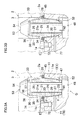
図1はクランピングシステムの横断面図である。図2Aは、上記クランピングシステムの第1クランプ装置の立面視の断面図であって、図1又は図2Bの2A−2A線の矢視図に相当する図である。図2Bは、上記クランプ装置の平面図である。図3Aから図4Bは、作動説明図である。図5Aから図5Cは、上記の第1クランプ装置の変形例を示している。図6Aと図6Bは、前記クランピングシステムの第2クランプ装置を示している。図6Cと図6Dは、それぞれ、上記の第2クランプ装置の変形例を示している。図7Aと図7Bは、前記クランピングシステムの第3クランプ装置を示している。FIG. 1 to FIG. 7B show an embodiment of the present invention, in which the clamping device of the present invention is applied to a clamping system for a work pallet.
FIG. 1 is a cross-sectional view of a clamping system. FIG. 2A is a cross-sectional view of the first clamping device of the clamping system as seen from an elevational view, corresponding to the view taken along the
この実施形態では、図1と図2Aに示すように、工作機械のテーブルTに基準ブロック1を載置し、その基準ブロック1の支持面1aに、可動ブロックとしてのワークパレット2の被支持面2aを受け止めるように構成してある。その被支持面2aには、円形のストレート孔からなるソケット孔3が複数開口される。ここでは、四つのソケット孔3を図示している。
In this embodiment, as shown in FIGS. 1 and 2A, a
上記の基準ブロック1は、上記テーブルTに固定したベースプレート4を備える。そのベースプレート4には、上記ソケット孔3に対応させて、位置決め機能とロック機能とを備えた第1クランプ装置11および第2クランプ装置12と、ロック機能だけを備えた二つの第3クランプ装置13・13とが設けられる。第1クランプ装置11と第2クランプ装置12とが対角線上に配置されると共に、二つの第3クランプ装置13・13も対角線上に配置されている。
The
上記の各クランプ装置11・12・13は、図1に示すように、後述する環状クランプ具33を楔作用によって放射状に拡径して、その環状クランプ具33の周壁のほぼ全周をソケット孔3に密着させた状態で下方へ駆動して、基準ブロック1にワークパレット2を固定する。
As shown in FIG. 1, each of the
第1クランプ装置11は、上記クランプ具33の密着とほぼ同時に基準ブロック1に対して後述の剛性スリーブ21(図3A参照)を水平方向かつ垂直方向へ位置決めする。また、第2クランプ装置12は、剛性スリーブ21(図6A参照)を基準軸心A・B同士を結ぶ直線Lにほぼ直交する水平方向へ位置決めすると共に垂直方向へも位置決めして、前記のワークパレット2が上記の軸心Aの回りに旋回するのを阻止する。なお、第3クランプ装置13は、基準ブロック1に対して剛性スリーブ21を水平方向へ移動可能に構成してあり(図7A及び図7Bを参照)、このため、垂直位置決め機能だけを備え、水平位置決め機能を備えてない。
The
上記の第1クランプ装置11と第2クランプ装置12とは、後述する相違点を除いて同一の構造であって、基本的には下記の構造が共通している。
The
図1から図2Bに示すように、前記ベースプレート4の装着穴4aにハウジング15の下部が嵌入され、そのハウジング15のフランジ16が4本の締付けボルト17によって上記の装着穴4aの周壁に固定される。
上記ハウジング15の上半部には、上下方向へ延びる中心孔20が、基準軸心A(図1と図2Aを参照)と同心状に形成される。その中心孔20は、前記ソケット孔3に対面可能に配置されている。上記の中心孔20に剛性スリーブ21が上下方向(軸心方向)へ移動可能に挿入されている。As shown in FIGS. 1 to 2B, the lower portion of the
A
上記の中心孔20と剛性スリーブ21とは、図3Aの拡大図に示すように、次のように構成されている。
上記の中心孔20の内周の上部と下部とに、それぞれテーパ内面23・23が形成される。各テーパ内面23は下方(基端方向)へ向かうにつれて縮径されている。
上記の剛性スリーブ21は、上記の中心孔20に挿入される基部24と、前記ソケット孔3に挿入可能な突出部25とを備える。その突出部25は、上記の中心孔20の上端よりも上方(先端方向)へ突出されている。
上記の基部24の外周面には、上記テーパ内面23にテーパ係合可能なテーパ外面27が設けられる。上記テーパ内面23及び上記テーパ外面27のテーパ角度は、約5度から約23度の範囲内であることが好ましく、さらに好ましいのは約10度から約16度の範囲内である。
また、上記の中心孔20の上方で前記の突出部25の下部からフランジ部28が半径方向の外方へ突出される。さらに、その突出部25の上部には、上方へ向かうにつれて縮径するテーパ外周面30が形成される。The
Tapered
The
A tapered
Further, the
剛性スリーブ21の上記テーパ外周面30に環状のクランプ具33のテーパ内周面34が上側から楔係合される。そのクランプ具33のストレート外周面35が前記ワークパレット2のソケット孔3に挿入可能になっている。上記クランプ具33はコレット形に形成されている。即ち、クランプ具33の周壁に上下方向へ延びる一つのスリット36を形成してあり、これにより、そのクランプ具33が直径方向へ拡大および縮小可能に構成されると共に自己の弾性復元力によって縮径される。
The tapered inner
前記の中心孔20の周壁の上部と前記フランジ部28との間に弾性部材(進出手段)45が配置される。その弾性部材45は、ゴム又は合成樹脂などのシール部材によって構成されており、剛性スリーブ21を上方(先端方向)へ押圧している。上記の剛性スリーブ21が所定量以上に上昇することは、その剛性スリーブ21の下部に装着したストッパー47によって阻止されている。
An elastic member (advancing means) 45 is disposed between the upper portion of the peripheral wall of the
前記ハウジング15内に出力部材48が上下移動自在に挿入される。その出力部材48は、ハウジング15の下部のシリンダ孔49に保密状に挿入したピストン50と、そのピストン50から上向きに突出されると共にロッド孔51に保密状に挿入されたピストンロッド52と、そのピストンロッド52にネジ止めした連結ロッド53とを備える。前記の剛性スリーブ21の筒孔21aに上記の連結ロッド53が挿入される。その連結ロッド53の上フランジ56と上記の連結ロッド53の頭部54との間に、前記クランプ具33の上フランジ57が半径方向へ摺動可能に嵌合されている。
An
図2Aに示すように、上記ハウジング15内には、駆動手段Dを構成するロック手段61およびリリース手段62が設けられる。そのロック手段61は、上記ピストン50と、そのピストン50の上側に形成したロック室63とによって構成される。そのロック室63がロック用の圧油給排口64へ連通される。また、上記リリース手段62は、上記ピストン50と、そのピストン50の下側に形成したリリース室66とによって構成される。そのリリース室66にリリース用の圧油給排口67が連通される。
なお、ロック用給排路69の縦路には絞りピン70が嵌合され、その嵌合隙間によって絞り路を構成している。As shown in FIG. 2A, the
A
上記ハウジング15の上面には周方向へ間隔をあけて複数のボス72が上方へ突出され、そのボス72の上面が基準ブロック1の支持面1aを構成している。
また、第1クランプ装置11には着座確認手段が設けられる。即ち、前記の支持面1aに検出孔74を開口し、その検出孔74に検出用の圧縮空気を供給する。そして、前記ワークパレット2の被支持面2aが上記の支持面1aに接当して着座隙間Eが消失すると、上記の検出孔74内の圧力が上昇する。その圧力上昇を圧力スイッチ等で検出することによって、ワークパレット2がハウジング15に着座したことを確認できる。A plurality of
The
さらに、図2Aと図3Aに示すように、ロック確認手段が設けられる。即ち、ロック確認用のエアー供給口76が、ハウジング15内の横路77と、下側のテーパ内面23とテーパ外面27との間のロック隙間Fと、前記ストッパー47に設けた連通溝(図示せず)と、上記の剛性スリーブ21の筒孔21aと連結ロッド53の外周面との間の隙間と、クランプ具33のスリット36とを順に通って、外部空間へ連通される。そして、テーパ内面23にテーパ外面27が接当して上記の連通を遮断すると、エアー供給口76の圧力が上昇する。その圧力上昇を圧力スイッチ等で検出することによって、クランプ具33及び剛性スリーブ21が下降してロック状態であることを確認するのである。
なお、上記ストッパー47に前記の連通溝(図示せず)を設けるとしたが、これに代えて、上側のテーパ内面23とテーパ外面27との間のロック隙間Fを連通路(図示せず)を介して剛性スリーブ21の筒孔21aに連通させてもよい。Furthermore, as shown in FIGS. 2A and 3A, a lock confirmation means is provided. That is, the
In addition, although the said communication groove | channel (not shown) was provided in the said
上記の各クランプ装置11・12・13の環状クランプ具33の周壁のほぼ全周が、剛性スリーブ21のテーパ外周面30によって半径方向の外方へ拡径されるようになっている(図1を参照)。
また、第1クランプ装置11の位置決め機構11aは、図2A及び図3A(及び後述の図5Bを参照)に示すように、前記の中心孔20の前記テーパ内面23のほぼ全周に、前記の剛性スリーブ21の前記テーパ外面27をテーパ係合可能に構成してある。Almost the entire circumference of the peripheral wall of the
Further, as shown in FIGS. 2A and 3A (and FIG. 5B to be described later), the
図5Aから図5Cは、上記の第1クランプ装置11の変形例を示している。図5Aは、前記の図3Aに類似する図である。図5Bは、上記の図5Aの5B−5B線の断面図である。図5Cは、同上の図5Aの5C−5C線の断面図である。
この場合、前記の連結ロッド53の頭部54とピストンロッド52との間にパイプ55が挟み付けられており、そのパイプ55内に連結ロッド53が挿入されている。また、前記の進出手段45は、上下方向に積層させた複数枚の皿バネによって構成してある。さらに、前記のコレット式のクランプ33の上半部の外周をカバー筒58によって覆ってある。このカバー筒58は、切粉等の異物が前記スリット36を通って剛性スリーブ21の内部へ侵入するのを防止してある。5A to 5C show a modification of the
In this case, a
図6A及び図6Bに示すように、前記の第2クランプ装置12の位置決め機構12aは、前記の第1クランプ装置11の位置決め機構11aとは次の構造が異なる。図6Aは、図6Bの6A−6A線の断面図であって、前記の図5Aに類似する図である。図6Bは、上記の図6Aの6B−6B線の断面図である。
前記の剛性スリーブ21の外周に、半径方向に向かい合う一対の突出部80・80が設けられ、各突出部80に前記テーパ外面27が形成される。そして、上記の中心孔20の上記の内周と上記の剛性スリーブ21の上記の外周との間に、上記の突出部80・80によって区画された移動許容スペース81・81が半径方向に向かい合うように形成されている。これにより、剛性スリーブ21は、上記突出部80・80の対面方向に嵌合隙間を無くすように機能し、一方、その対面方向に対して直交する半径方向へ剛性スリーブ21が移動することが許容される。なお、図6Aと図6B中の参照数字82は回り止めピンである。As shown in FIGS. 6A and 6B, the
A pair of projecting
図6Cは、上記の位置決め機構12aの第1変形例を示している。この場合、前記の中心孔20の内周に、半径方向に向かい合う一対の突出部80・80が設けられ、各突出部80に前記テーパ内面23が形成される。また、前記の一対の移動許容スペース81・81も図6Bと同様に形成されている。
FIG. 6C shows a first modification of the
図6Dの第2変形例は、上記の図6Cの第1変形例を次のように変更したものである。即ち、前記テーパ内面23と前記テーパ外面27とが、円周面に代えて平面で構成されている。
The second modification of FIG. 6D is obtained by changing the first modification of FIG. 6C as follows. That is, the taper
前記の第3クランプ装置13は、図7Aと図7Bに示すように、上記の第1クランプ装置11とは次の構造が異なる。
前記の中心孔20の内周面と剛性スリーブ21の外周面との両周面が上下方向へストレートに形成され、これら両周面の間に、その剛性スリーブ21が半径方向へ移動するのを許容する環状隙間Gが設けられる。これにより、前記ソケット孔3の軸心と中心孔20の軸心との心ズレを吸収できる。
なお、環状ゴム製の進出手段45の外周にはダストシール46を装着してある。As shown in FIGS. 7A and 7B, the
Both peripheral surfaces of the inner peripheral surface of the
A
上記の各クランプ装置11・12・13は、ほぼ同様に、次のように作動する。
上記の図2Aと図3Aのリリース状態では、ロック室63の圧油を排出すると共にリリース室66へ圧油を供給している。これにより、ピストン50が連結ロッド53を介して環状クランプ具33を上昇させ、そのクランプ具33が縮径状態へ切り換えられている。剛性スリーブ21は、進出手段としての弾性部材45によって進出ストロークだけ上昇して、上記クランプ具33に軽くテーパ係合するか又は上記クランプ具33に僅かな隙間をあけて対面している。Each of the
2A and 3A, the pressure oil in the
基準ブロック1にワークパレット2を位置決めするときには、まず、図1と図2A(及び図3A)に示すように、上記リリース状態でワークパレット2を下降させてソケット孔3を上記クランプ具33に外嵌させ,そのワークパレット2を剛性スリーブ21のフランジ部28によって受け止める。この状態では、支持面1aと被支持面2aとの間には前記の着座隙間Eが形成されている。また、図3Aに示すように、テーパ内面23とテーパ外面27との間には前記ロック隙間Fが形成され、ピストンロッド52の上端面と剛性スリーブ21の下端面との間には微小な接当隙間N1が形成されている。
なお、上記のようにロック隙間Fを設けたので、ワークパレット2のソケット孔3を上記クランプ具33に嵌合させるときに、そのソケット孔3の軸心と剛性スリーブ21の軸心との心ズレを許容できる。When positioning the
Since the lock gap F is provided as described above, when the
次いで、前記リリース室66の圧油を排出すると共に前記ロック室63へ圧油を供給する。すると、ピストン50が連結ロッド53を介してクランプ具33を下降させ、そのクランプ具33の前記テーパ内周面34が剛性スリーブ21のテーパ外周面30に楔係合していく。
Next, the pressure oil in the
これにより、図3Bに示すように、前記の弾性部材45の付勢力によってほぼ上昇位置に保持された剛性スリーブ21に対してクランプ具33が拡径して前記のソケット孔3に接当する。この図3Bのロック開始状態では、ピストンロッド52の上端面と剛性スリーブ21の下端面との間には、図3Aの前記の接当隙間N1よりも大きい接当隙間N2が形成されている。
As a result, as shown in FIG. 3B, the
次いで、図4Aに示すように、そのクランプ具33が、剛性スリーブ21を介して弾性部材45を下方へ圧縮しながら拡径して上記ソケット孔3に密着する。これとほぼ同時に、前記ワークパレット2の被支持面2aが前記の基準ブロック1の前記の支持面1aに接当する。そして、この図4Aのロック途中状態では、前記ストッパー47の上方に、前記の図3Bの着座隙間Eに相当する下降ストロークM1が形成され、ピストンロッド52の上端面と剛性スリーブ21の下端面との間には、前記の図3Bの接当隙間N2よりも少し大きい接当隙間N3が形成されている。
Next, as shown in FIG. 4A, the
引き続いて、図4Bに示すように、上記ソケット孔3の内周面に対して上記クランプ具33が下方へ摺動しながら移動して、そのクランプ具33が前記の弾性部材45を圧縮しながら剛性スリーブ21をさらに下降させていく。そして、その剛性スリーブ21が前記の進出ストロークに相当する下降ストロークM2だけ下降したときに、上記の剛性スリーブ21のテーパ面27が中心孔20のテーパ内面23にテーパ係合する。
これにより、上記の剛性スリーブ21は、上記テーパ係合を介して、半径方向(水平方向)および軸心方向(上下方向)方向で基準ブロック1に拘束される。そして、ワークパレット2は、上記の拘束状態の剛性スリーブ21とソケット孔3に密着したクランプ具33とを介して前記ハウジング15に水平方向に位置決めされる。Subsequently, as shown in FIG. 4B, the
Thereby, the
これとほぼ同時に、上記の剛性スリーブ21に対して出力部材48がさらに下降駆動されることにより、上記ハウジング15に受け止められた剛性スリーブ21のテーパ外周面30にクランプ具33のテーパ内周面34が強力に楔係合して拡径して、そのクランプ具33のストレート外周面35が前記ソケット孔3に強力に密着する。そして、連結ロッド53が上記の強力に密着したクランプ具33を介して前記ワークパレット2の被支持面2aを前記の基準ブロック1の支持面1aに強力に押圧する。
At substantially the same time, the
上記の図4Bのロック終了状態では、上記の剛性スリーブ21のテーパ外面27が中心孔20のテーパ内面23にテーパ係合することにより、ロック確認用エアー供給口76の圧力が上昇し、その圧力上昇を検出することにより、ロック状態であることを確認できる。また、被支持面2aが支持面1aに接当することにより、検出孔74の圧力が上昇し、その圧力上昇を検出することにより、ワークパレット2が着座していることを確認できる。
4B, when the tapered
なお、前記図3Aのリリース状態および図3Bのロック開始時において、上記の支持面1aと上記の被支持面2aとがほぼ完全に接当するようにしてもよい。この場合、そのロック移動時にクランプ具33が次のように作動する。
クランプ具33は、上記ソケット孔3に密着した後、そのソケット孔3に対して摺動しながら下降していく。そして、前述したように、剛性スリーブ21のテーパ外面27がテーパ内面23にテーパ係合したときに、クランプ具33がソケット孔3に強力に密着し、そのクランプ具33が上記ワークパレット2を上記の基準ブロック1へ強力に押圧する。Note that the
After the
上記の第1クランプ装置11と第2クランプ装置12の作動と同時に、ロック機能だけを備えた前記二つの第3クランプ装置13・13が上記クランプ具33を介して上記ワークパレット2を前記の基準ブロック1に強力に固定するのである。
上記ロック状態から前記リリース状態へ切り換えるときには、前述したように前記ロック室63の圧油を排出すると共に前記リリース室66へ圧油を供給すればよい。これにより、ピストン50が連結ロッド53を介してクランプ具33を上昇させて、そのクランプ具33が自己の弾性復元力によって縮径するので、前記ロック状態が解除される。
なお、上記リリース駆動時には、図3Aに示す前記の接当隙間N1を無くして、ピストンロッド52が剛性スリーブ21を強制的に押し上げるようにしてもよい。Simultaneously with the operation of the
When switching from the lock state to the release state, the pressure oil in the
During the release drive, the contact gap N1 shown in FIG. 3A may be eliminated, and the
図8と図9Aから図9Dとは、それぞれ、本発明に係る第1クランプ装置11の第2実施形態と第3実施形態とを示している。これらの別の実施形態においては、上記の第1実施形態の構成部材と類似する部材には原則として同一の符号を付けてあり、上述した第1実施形態とは異なる構成について説明する。
8 and 9A to 9D show a second embodiment and a third embodiment of the
図8の第2実施形態は、前記の図2Aに類似する図である。この場合、前記の駆動手段Dを人力式に構成してある。
より詳しくいえば、前記の連結ロッド53の下部が、前記ベースプレート4のネジ孔88に螺合される。そして、ロック駆動時には、連結ロッド53の頭部54の入力穴89に六角レンチ90を挿入して連結ロッド53を平面視で時計回りの方向へ回転させる。すると、その頭部54が前記クランプ具33を拡径させながら下降させるのである。
また、弾性部材(進出手段)45は、断面視で横U字状に形成されている。
なお、上記ベースプレート4とハウジング15は、例示したように別体に構成することに代えて、一体に形成することも可能である。The second embodiment of FIG. 8 is similar to FIG. 2A. In this case, the driving means D is constructed manually.
More specifically, the lower portion of the connecting
Further, the elastic member (advancing means) 45 is formed in a horizontal U shape in a sectional view.
The
上記の各実施形態のクランプ具33は、各周壁に一つのスリット36を設けたものに代えて、各周壁の上面と下面に交互に開口する複数の貫通溝を周方向へ複数設けたものであってよい。また、上記クランプ具33を、周方向へ並べた複数の分割体によって構成することも可能である。
なお、上記クランプ具33の外面は、上下方向にストレートに形成することに代えて、鋸刃状または凹凸状に形成してもよい。また、上記クランプ具33は、上述した構造に限定されるものではなく、公知の各種構造を採用できることは勿論である。The
The outer surface of the
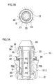
図9Aから図9Dは、第1クランプ装置11の第3実施形態を示している。図9Aは、そのクランプ装置11のリリース状態を示し、図9Bの9A−9A線の矢視図に相当する断面図である。図9Bは、図9Aの平面視の断面図である。図9Cは、上記クランプ装置のロック状態を示し、図9Aに類似する図である。図9Dは、図9Cの平面視の断面図である。
9A to 9D show a third embodiment of the
前記の剛性スリーブ21は、頂壁21bを備えている。また、その剛性スリーブ21の前記の突出部25の周壁25aに、半径方向へ延びる3つの貫通孔95が周方向へ間隔をあけて形成される。各貫通孔95にボール96が半径方向へ移動可能に挿入される。その貫通孔95の外端部を縮径することにより、上記ボール96が外方へ抜け出るのを防止してある。上記の複数のボール96が前記クランプ具33を構成している。
前記の出力部材48の前記の連結ロッド53の上部(先端部)には、上記の各ボール96に対応させて、上下方向へ延びる溝97が形成される。その溝97は出力面98と退避面99とを備えている。The
A
図9Aと図9Bのリリース状態では、前記の剛性スリーブ21は、前記の弾性部材45の付勢力によって上昇位置に保持されている。また、その剛性スリーブ21に対して前記の出力部材48が上昇し、上記の退避面99が上記ボール96に対面している。このため、各ボール96が半径方向の内方の係合解除位置Yに切り換え可能になっている(ここでは、ボール96が既に係合解除位置Yに切り換わった状態を示している)。
9A and 9B, the
基準ブロック1にワークパレット2を位置決めするときには、まず、図9Aに示すように、上記リリース状態でワークパレット2を下降させてソケット孔3を上記の複数のボール96に外嵌させ、そのワークパレット2を剛性スリーブ21のフランジ部28によって受け止める。
この状態では、支持面1aと被支持面2aとの間には前記の着座隙間Eが形成され、テーパ内面23とテーパ外面27との間には前記ロック隙間Fが形成されている。When positioning the
In this state, the seating gap E is formed between the
ロック駆動時には、前記の出力部材48を下降させる。すると、前記の連結ロッド53の出力面98が上記ボール96を外方へ押し出していく。これにより、上記の剛性スリーブ21の貫通孔95内を上記ボール96が半径方向の外方へ移動し、各ボール96が前記のソケット孔3に接当する。
During the lock driving, the
次いで、図9C及び図9Dに示すように、半径方向の外方の係合位置Xへ切り換えられたボール96が、剛性スリーブ21を介して弾性部材45を下方へ圧縮しながら上記ソケット孔3に密着し、これとほぼ同時に、前記ワークパレット2の被支持面2aが前記の基準ブロック1の前記の支持面1aに接当する。
引き続いて、上記ソケット孔3の内周面に対して上記の複数のボール96が下方へ摺動しながら(又は、上記ボール96が上記ソケット孔3の内周面を弾性変形または塑性変形させながら)移動すると共に、上記の複数のボール96が前記の弾性部材45に抗して上記の剛性スリーブ21をさらに下降させていき、その剛性スリーブ21のテーパ外面27が中心孔20のテーパ内面23にテーパ係合する。
これにより、上記の剛性スリーブ21は、上記テーパ係合を介して、半径方向(水平方向)および軸心方向(上下方向)で基準ブロック1に拘束される。そして、ワークパレット2は、上記の拘束状態の剛性スリーブ21とソケット孔3に密着した複数のボール96を介して前記ハウジング15に水平方向に位置決めされる。Next, as shown in FIGS. 9C and 9D, the
Subsequently, the plurality of
Thereby, the
これとほぼ同時に、上記の剛性スリーブ21に対して出力部材48がさらに下降駆動されることにより、上記の複数のボール96が前記ソケット孔3に強力に密着する。そして、連結ロッド53が上記の強力に密着したボール96を介して前記ワークパレット2の被支持面2aを前記の基準ブロック1の支持面1aに強力に押圧する。
なお、前記貫通孔95及びボール96の各設置数は、3つ設けることに代えて、2つ又は4つ以上設けてもよい。At substantially the same time, the
It should be noted that the number of the through
上記の各実施形態や変形例は次のように変更可能である。
前記の中心孔20のテーパ内面23は、上下方向に2つ又は1つ設けることに代えて、3つ以上設けてもよい。
その中心孔20のテーパ内面23や剛性スリーブ21のテーパ外面27は、断面視で円形のテーパ面が好ましいが、これに代えて、楕円形のテーパ面であってもよく、又は、周方向へ所定の間隔をあけて配置した複数の傾斜形の楔面であってもよい。この場合、上記テーパ内面23やテーパ外面27には、周方向へ所定の間隔をあけて複数の傾斜溝を配置して、その傾斜溝の底壁によって上記の楔面を構成してもよい。Each of the above-described embodiments and modifications can be changed as follows.
Three or more tapered
The tapered
前記の進出手段45は、前記の剛性スリーブ21を上方(先端方向)へ押圧するものであればよい。従って、その進出手段45は、その剛性スリーブ21の前記フランジ部28と前記ハウジング15との間に装着することに代えて、剛性スリーブ21の下部と前記ハウジング15との間に装着してもよい。また、上記の進出手段45は、例示したゴム等の弾性部材や皿バネ等のバネに代えて、又は、これに加えて、圧縮空気や圧油等の圧力流体とピストンとの組み合わせを利用してもよい。
The advancement means 45 may be anything that presses the
上記の各クランプ装置11・12・13にクリーニング手段を設けて、前記の支持面1aと被支持面2aとの接当部や、前記のソケット孔3とクランプ具33との嵌合部や、前記ボール96と貫通孔95との嵌合部や、前記テーパ内面23やテーパ外面27との各嵌合面などを圧縮空気等の圧力流体によってクリーニングすることが好ましい。
クランピングシステムにおいては、ロック機能だけを備えた前記の第3クランプ装置13は、例示した二つに代えて、一つだけ設置してもよく、又は三つ以上設置してもよい。その第3クランプ装置13は、例示の構造に限定されるものではなく、別の種類のクランプであってもよい。Provided with a cleaning means in each of the
In the clamping system, the
各クランプ装置11・12・13の駆動形式は、例示した油圧複動式に代えて、バネロックかつ油圧リリース式、又は、油圧ロックかつバネリリース式であってもよい。
ロック又はリリースに使用する圧力流体は、例示の圧油に代えて、圧縮空気等のガスであってもよい。また、クリーニング用の圧力流体は、例示の圧縮空気に代えて、窒素等のガスや液体であってもよい。
前記のロック駆動時におけるクランプの引き下げ力を十分に大きい値に設定した場合には、上記の第3クランプ装置13を省略可能である。
また、クランピングシステムにおいては、前記の第1クランプ装置11を複数設置すると共に前記の第2クランプ装置12を複数設置してもよい。さらに、第1クランプ装置11と第2クランプ装置12の両者のうちのいずれか一方だけを複数設置してもよい。The drive type of each
The pressure fluid used for locking or releasing may be a gas such as compressed air instead of the illustrated pressure oil. Further, the pressure fluid for cleaning may be a gas such as nitrogen or a liquid instead of the exemplified compressed air.
When the pulling force of the clamp during the lock driving is set to a sufficiently large value, the
In the clamping system, a plurality of the
上記の複数のクランプ装置を並べて設置する方向としては、円周方向や直線方向などが考えられる。
前記の支持面1aは、前記ハウジング15のボス72の上面に設けることに代えて、前記ベースプレート4に設けてもよい。
また、上記ハウジング15と前記ベースプレート4とは、別体に形成することに代えて、一体に形成してもよい。As a direction in which the plurality of clamping devices are installed side by side, a circumferential direction, a linear direction, or the like can be considered.
The
The
前記の基準ブロックと可動ブロックとの組み合わせは、例示したベースプレート4とワークパレット2の組み合わせに代えて、工作機械のテーブルとワークパレットの組み合わせ、ワークパレットと治具ベースの組み合わせ、治具ベースとワークピースの組み合わせ、溶接治具等の作業用治具とワークピース等の作業物の組み合わせであってもよい。また、本発明は、レーザー加工機や放電加工機などの各種の加工機械のワークピース・ツール等の位置決めにも適用可能である。
なお、本発明のクランプ装置は、複数セットで使用することに代えて、1セットだけで使用できることは勿論である。The combination of the reference block and the movable block is not the combination of the illustrated
Of course, the clamping device of the present invention can be used in only one set instead of being used in a plurality of sets.
Claims (13)
上記の基準ブロック(1)に、基端方向へ狭まるテーパ内面(23)を有する中心孔(20)を、上記ソケット孔(3)に対面可能に設け、
上記の中心孔(20)の上記テーパ内面(23)にテーパ係合可能なテーパ外面(27)と同上の中心孔(20)よりも先端方向へ突出されて前記ソケット孔(3)に挿入可能な突出部(25)と軸心方向へ延びる筒孔(21a)とを有する剛性スリーブ(21)を、その軸心方向へ所定範囲内で移動可能なように上記の基準ブロック(1)に支持し、
上記の剛性スリーブ(21)を進出手段(45)によって先端方向へ押圧し、
上記の剛性スリーブ(21)の前記の筒孔(21a)に出力部材(48)を挿入し、その出力部材(48)を、前記ソケット孔(3)に挿入されるように前記の突出部(25)に設けたクランプ具(33)に連結可能に構成し、
駆動手段(D)が上記の出力部材(48)を基端方向へ移動させることにより、その出力部材(48)が、前記の進出手段(45)に抗して上記クランプ具(33)を基端方向かつ半径方向の外方へロック移動させると共に、前記の剛性スリーブ(21)の前記テーパ外面(27)を前記の中心孔(20)の前記テーパ内面(23)にテーパ係合させる、ことを特徴とするクランプ装置。A device for clamping a movable block (2) having a socket hole (3) to a reference block (1),
A center hole (20) having a tapered inner surface (23) narrowing in the proximal direction is provided in the reference block (1) so as to face the socket hole (3).
The center hole (20) protrudes in the distal direction from the center hole (20) which is the same as the taper outer surface (27) which can be taper-engaged with the taper inner surface (23) and can be inserted into the socket hole (3). A rigid sleeve (21) having a projecting portion (25) and a cylindrical hole (21a) extending in the axial direction is supported by the reference block (1) so as to be movable within a predetermined range in the axial direction. And
The rigid sleeve (21) is pressed toward the distal end by the advance means (45),
An output member (48) is inserted into the cylindrical hole (21a) of the rigid sleeve (21), and the output member (48) is inserted into the socket hole (3) so that the protrusion ( 25) that can be connected to the clamp device (33) provided in
The drive means (D) moves the output member (48) in the proximal direction, so that the output member (48) is based on the clamp (33) against the advance means (45). Locking and moving the taper outer surface (27) of the rigid sleeve (21) to the taper inner surface (23) of the center hole (20) while locking and moving outward and radially outward. A clamping device characterized by the above.
前記の中心孔(20)の外方で前記の剛性スリーブ(21)から半径方向の外方へフランジ部(28)を突出させ、そのフランジ部(28)と前記の基準ブロック(1)との間に前記の進出手段(45)を環状に配置した、ことを特徴とするクランプ装置。The clamping device according to claim 1, wherein
A flange portion (28) protrudes radially outward from the rigid sleeve (21) outside the center hole (20), and the flange portion (28) and the reference block (1) are connected to each other. A clamping device characterized in that the advancing means (45) is arranged in an annular shape in between.
前記の環状の進出手段(45)を、ゴム又は合成樹脂等のシール用の弾性部材によって構成した、ことを特徴とするクランプ装置。The clamping device of claim 2,
The clamping device according to claim 1, wherein the annular advancing means (45) is constituted by an elastic member for sealing such as rubber or synthetic resin.
前記の中心孔(20)の外方で前記の剛性スリーブ(21)から半径方向の外方へフランジ部(28)を突出させ、そのフランジ部(28)に前記の可動ブロック(2)を載置した状態では、前記進出手段(45)が上記の可動ブロック(2)を押圧して、その可動ブロック(2)の被支持面(2a)と前記の基準ブロック(1)の支持面(1a)との間に着座隙間(E)が形成されるように構成し、
上記の支持面(1a)に、着座確認用の圧力流体の検出孔(74)を開口させた、ことを特徴とするクランプ装置。The clamping device according to claim 1, wherein
A flange portion (28) protrudes radially outward from the rigid sleeve (21) outside the center hole (20), and the movable block (2) is mounted on the flange portion (28). In the placed state, the advancement means (45) presses the movable block (2), and the supported surface (2a) of the movable block (2) and the support surface (1a of the reference block (1)). ) To form a seating gap (E),
A clamping device, wherein a detection hole (74) for pressure fluid for seating confirmation is opened on the support surface (1a).
前記の基準ブロック(1)に、ロック確認用の圧力流体の供給口(76)を設け、その供給口(76)を、前記テーパ内面(23)と前記テーパ外面(27)との間のロック隙間(F)を介して外部空間へ連通させ、上記テーパ外面(27)が上記テーパ内面(23)にテーパ係合したときに上記の供給口(76)と外部空間との連通状態を遮断するように構成した、ことを特徴とするクランプ装置。The clamping device according to claim 1, wherein
The reference block (1) is provided with a supply port (76) of pressure fluid for lock confirmation, and the supply port (76) is a lock between the tapered inner surface (23) and the tapered outer surface (27). When the tapered outer surface (27) is taper-engaged with the tapered inner surface (23), the communication state between the supply port (76) and the outer space is shut off. A clamping device characterized in that it is configured as described above.
前記の基準ブロック(1)に設けた前記の中心孔(20)の前記テーパ内面(23)のほぼ全周に、前記の剛性スリーブ(21)の前記テーパ外面(27)をテーパ係合可能に構成した、ことを特徴とするクランプ装置。The clamping device according to any one of claims 1 to 5,
The taper outer surface (27) of the rigid sleeve (21) can be taper-engaged on substantially the entire circumference of the taper inner surface (23) of the center hole (20) provided in the reference block (1). A clamping device characterized by comprising.
前記の基準ブロック(1)に設けた前記の中心孔(20)の内周と前記の剛性スリーブ(21)の外周との少なくとも一方に、半径方向に向かい合う一対の突出部(80)(80)を設け、上記の各突出部(80)に前記テーパ内面(23)又は前記テーパ外面(27)を形成し、
上記の中心孔(20)の上記の内周と上記の剛性スリーブ(21)の上記の外周との間に、上記の突出部(80)(80)によって区画された移動許容スペース(81)(81)を半径方向に向かい合うように形成した、ことを特徴とするクランプ装置。The clamping device according to any one of claims 1 to 5,
A pair of projecting portions (80), (80) facing radially in at least one of an inner periphery of the center hole (20) provided in the reference block (1) and an outer periphery of the rigid sleeve (21). Forming the taper inner surface (23) or the taper outer surface (27) on each of the protrusions (80),
Between the inner periphery of the center hole (20) and the outer periphery of the rigid sleeve (21), a movement-permissible space (81) defined by the protrusions (80) (80) ( 81) is formed so as to face in the radial direction.
前記クランプ具(33)を直径方向へ拡大および縮小可能なコレットによって構成し、上記コレット式のクランプ具(33)を前記の剛性スリーブ(21)の前記の突出部(25)に先端側から楔係合させた、ことを特徴とするクランプ装置。The clamping device according to any one of claims 1 to 5,
The clamp device (33) is constituted by a collet that can be expanded and contracted in the diametrical direction, and the collet-type clamp device (33) is wedged from the distal end side to the protruding portion (25) of the rigid sleeve (21). A clamping device characterized by being engaged.
前記の剛性スリーブ(21)の前記の突出部(25)の周壁に周方向へ間隔をあけて配置した複数のボール(96)によって前記クランプ具(33)を構成し、前記の出力部材(48)が上記の各ボール(96)を半径方向の外方の係合位置(X)へ切り換えるように構成した、ことを特徴とするクランプ装置。The clamping device according to any one of claims 1 to 5,
The clamp member (33) is composed of a plurality of balls (96) arranged at intervals in the circumferential direction on the peripheral wall of the protrusion (25) of the rigid sleeve (21), and the output member (48). ) Is configured to switch each of the balls (96) to an outward engagement position (X) in the radial direction.
前記ボール(96)を少なくとも3つ設けた、ことを特徴とするクランプ装置。The clamping device according to claim 9, wherein
A clamping device comprising at least three balls (96).
Priority Applications (1)
| Application Number | Priority Date | Filing Date | Title |
|---|---|---|---|
| JP2007546465A JP4896889B2 (en) | 2005-11-28 | 2006-11-22 | CLAMPING DEVICE AND CLAMPING SYSTEM USING THE DEVICE |
Applications Claiming Priority (4)
| Application Number | Priority Date | Filing Date | Title |
|---|---|---|---|
| JP2005376357 | 2005-11-28 | ||
| JP2005376357 | 2005-11-28 | ||
| JP2007546465A JP4896889B2 (en) | 2005-11-28 | 2006-11-22 | CLAMPING DEVICE AND CLAMPING SYSTEM USING THE DEVICE |
| PCT/JP2006/323309 WO2007060986A1 (en) | 2005-11-28 | 2006-11-22 | Clamp device and clamping system using such device |
Publications (2)
| Publication Number | Publication Date |
|---|---|
| JPWO2007060986A1 JPWO2007060986A1 (en) | 2009-05-07 |
| JP4896889B2 true JP4896889B2 (en) | 2012-03-14 |
Family
ID=38067211
Family Applications (1)
| Application Number | Title | Priority Date | Filing Date |
|---|---|---|---|
| JP2007546465A Expired - Fee Related JP4896889B2 (en) | 2005-11-28 | 2006-11-22 | CLAMPING DEVICE AND CLAMPING SYSTEM USING THE DEVICE |
Country Status (8)
| Country | Link |
|---|---|
| US (1) | US20090315239A1 (en) |
| EP (1) | EP1961516B1 (en) |
| JP (1) | JP4896889B2 (en) |
| KR (1) | KR20080072907A (en) |
| CN (1) | CN100563920C (en) |
| AT (1) | ATE462530T1 (en) |
| DE (1) | DE602006013349D1 (en) |
| WO (1) | WO2007060986A1 (en) |
Cited By (1)
| Publication number | Priority date | Publication date | Assignee | Title |
|---|---|---|---|---|
| TWI609745B (en) * | 2015-07-02 | 2018-01-01 | 嘉新精密有限公司 | A flexible positioning block with lateral clamping structure |
Families Citing this family (28)
| Publication number | Priority date | Publication date | Assignee | Title |
|---|---|---|---|---|
| JP5184505B2 (en) * | 2007-02-23 | 2013-04-17 | 株式会社コスメック | Clamp motion detection device |
| JP4297511B1 (en) * | 2008-02-15 | 2009-07-15 | パスカルエンジニアリング株式会社 | Clamping device |
| JP4302174B1 (en) * | 2008-02-15 | 2009-07-22 | パスカルエンジニアリング株式会社 | Clamping device |
| JP5346542B2 (en) | 2008-04-24 | 2013-11-20 | パスカルエンジニアリング株式会社 | Clamping device |
| JP5435908B2 (en) * | 2008-08-06 | 2014-03-05 | パスカルエンジニアリング株式会社 | Clamping device |
| JP2010099785A (en) * | 2008-10-24 | 2010-05-06 | Pascal Engineering Corp | Work pallet positioning and fixing mechanism |
| JP5276519B2 (en) * | 2009-05-26 | 2013-08-28 | 株式会社神戸製鋼所 | Clamping device |
| JP5385710B2 (en) * | 2009-07-09 | 2014-01-08 | パスカルエンジニアリング株式会社 | Clamping device |
| JP5674191B2 (en) * | 2010-03-01 | 2015-02-25 | パスカルエンジニアリング株式会社 | Clamping device |
| JP2012042185A (en) | 2010-08-23 | 2012-03-01 | Mitsubishi Heavy Ind Ltd | Clamper, and in-water-chamber operation device |
| JP2012040674A (en) * | 2010-08-23 | 2012-03-01 | Mitsubishi Heavy Ind Ltd | Clamper, working device in water chamber, and clamp method |
| CN101954607B (en) * | 2010-08-30 | 2011-12-14 | 常州市第八纺织机械有限公司 | Drill clamp for connecting rod rest of needle core bed |
| CN102059562A (en) * | 2010-11-15 | 2011-05-18 | 吴江市菀坪镙丝厂 | Cylinder member fixture |
| CN102756561B (en) * | 2011-04-29 | 2014-12-03 | 金宝电子工业股份有限公司 | Fluid detection jig |
| CN102248413A (en) * | 2011-07-19 | 2011-11-23 | 重庆市蓝黛实业有限公司 | Pull key groove clamp |
| CN102357448B (en) * | 2011-08-31 | 2013-03-27 | 奇瑞汽车股份有限公司 | Workpiece fixing device capable of automatic detection of workpiece specification |
| JP5996306B2 (en) * | 2012-07-04 | 2016-09-21 | パスカルエンジニアリング株式会社 | Object positioning and fixing device |
| ITTV20120129A1 (en) * | 2012-07-11 | 2014-01-12 | Almerino Canuto | EXCEPTIONAL COMPENSATION DEVICE IN AUTOMATIC LOCKING SYSTEMS |
| CN104209891B (en) * | 2013-05-31 | 2016-12-28 | 富泰华工业(深圳)有限公司 | The swelling assembly of detent mechanism and employing thereof |
| DE102013222089A1 (en) * | 2013-10-30 | 2015-04-30 | Trumpf Sachsen Gmbh | Coupling device and coupling arrangement for connecting two components of a mechanical arrangement for workpiece machining, in particular for sheet metal processing |
| FR3017556B1 (en) * | 2014-02-14 | 2016-09-16 | Snecma | PART CLAMPING SYSTEM AND METHOD FOR SEALING THE INTERNAL VIROL OF A TURBOMACHINE LOW PRESSURE RECTIFIER |
| CN105436910A (en) * | 2015-06-12 | 2016-03-30 | 新兴重工湖北三六一一机械有限公司 | Fast clamp replacing device |
| JP6683472B2 (en) * | 2015-11-30 | 2020-04-22 | 株式会社コスメック | Clamp device |
| ITUB20160781A1 (en) * | 2016-01-27 | 2017-07-27 | Hydroblock S R L | DEVICE FOR LOCKING PIECES ON MACHINE TOOLS |
| CN107127694A (en) * | 2017-06-01 | 2017-09-05 | 广西汽车集团有限公司 | A kind of whorl work piece clamping tool |
| CN109128894B (en) * | 2017-06-28 | 2024-03-19 | 杨斌堂 | Pipe clamping mechanism |
| CN110524269A (en) * | 2019-08-20 | 2019-12-03 | 浙江吉孚汽车传动系统有限公司 | Planet carrier fixture for processing |
| CN110509070B (en) * | 2019-08-30 | 2020-07-03 | 北京智同精密传动科技有限责任公司 | Planet carrier eccentric machining tool and machining process thereof |
Citations (5)
| Publication number | Priority date | Publication date | Assignee | Title |
|---|---|---|---|---|
| JPH11188551A (en) * | 1997-12-24 | 1999-07-13 | Kosmek Ltd | Clamp device |
| JP2001038564A (en) * | 1999-08-03 | 2001-02-13 | Kosmek Ltd | Clamping device with datum function |
| WO2004067224A1 (en) * | 2003-01-29 | 2004-08-12 | Kosmek Ltd. | Clamping device and clamping system using the same |
| WO2005009676A1 (en) * | 2003-07-25 | 2005-02-03 | Kosmek Ltd. | Clamp device |
| JP2006231501A (en) * | 2005-02-23 | 2006-09-07 | Kosmek Ltd | Clamping device, and clamping system using it |
Family Cites Families (3)
| Publication number | Priority date | Publication date | Assignee | Title |
|---|---|---|---|---|
| JPH01170532A (en) * | 1987-12-25 | 1989-07-05 | Kosumetsuku:Kk | Cylinder type hydraulic clamp |
| JP3663479B2 (en) * | 1998-10-07 | 2005-06-22 | オークマ株式会社 | Workpiece positioning jig for machine tools |
| EP1552901B1 (en) * | 2002-08-06 | 2007-05-23 | Kosmek Ltd. | Clamp device |
-
2006
- 2006-11-22 CN CNB2006800442725A patent/CN100563920C/en not_active Expired - Fee Related
- 2006-11-22 US US12/084,954 patent/US20090315239A1/en not_active Abandoned
- 2006-11-22 JP JP2007546465A patent/JP4896889B2/en not_active Expired - Fee Related
- 2006-11-22 WO PCT/JP2006/323309 patent/WO2007060986A1/en active Application Filing
- 2006-11-22 AT AT06833131T patent/ATE462530T1/en not_active IP Right Cessation
- 2006-11-22 DE DE602006013349T patent/DE602006013349D1/en active Active
- 2006-11-22 KR KR1020087013919A patent/KR20080072907A/en not_active Application Discontinuation
- 2006-11-22 EP EP06833131A patent/EP1961516B1/en not_active Not-in-force
Patent Citations (5)
| Publication number | Priority date | Publication date | Assignee | Title |
|---|---|---|---|---|
| JPH11188551A (en) * | 1997-12-24 | 1999-07-13 | Kosmek Ltd | Clamp device |
| JP2001038564A (en) * | 1999-08-03 | 2001-02-13 | Kosmek Ltd | Clamping device with datum function |
| WO2004067224A1 (en) * | 2003-01-29 | 2004-08-12 | Kosmek Ltd. | Clamping device and clamping system using the same |
| WO2005009676A1 (en) * | 2003-07-25 | 2005-02-03 | Kosmek Ltd. | Clamp device |
| JP2006231501A (en) * | 2005-02-23 | 2006-09-07 | Kosmek Ltd | Clamping device, and clamping system using it |
Cited By (1)
| Publication number | Priority date | Publication date | Assignee | Title |
|---|---|---|---|---|
| TWI609745B (en) * | 2015-07-02 | 2018-01-01 | 嘉新精密有限公司 | A flexible positioning block with lateral clamping structure |
Also Published As
| Publication number | Publication date |
|---|---|
| CN100563920C (en) | 2009-12-02 |
| CN101316678A (en) | 2008-12-03 |
| EP1961516A1 (en) | 2008-08-27 |
| ATE462530T1 (en) | 2010-04-15 |
| KR20080072907A (en) | 2008-08-07 |
| JPWO2007060986A1 (en) | 2009-05-07 |
| WO2007060986A1 (en) | 2007-05-31 |
| DE602006013349D1 (en) | 2010-05-12 |
| EP1961516A4 (en) | 2009-06-10 |
| US20090315239A1 (en) | 2009-12-24 |
| EP1961516B1 (en) | 2010-03-31 |
Similar Documents
| Publication | Publication Date | Title |
|---|---|---|
| JP4896889B2 (en) | CLAMPING DEVICE AND CLAMPING SYSTEM USING THE DEVICE | |
| JP4954899B2 (en) | Positioning device and positioning system | |
| US7168695B2 (en) | Positioning device | |
| EP1598144B1 (en) | Clamping device and clamping system using the same | |
| JP4260488B2 (en) | Alignment drive mechanism and positioning device provided with the mechanism | |
| JP4864164B2 (en) | Clamping system with fluid coupler | |
| WO2011046039A1 (en) | Clamp device | |
| EP1302278A1 (en) | Clamping apparatus | |
| JP2001038564A (en) | Clamping device with datum function | |
| EP1649973B1 (en) | Clamp device | |
| JP4607635B2 (en) | CLAMPING DEVICE AND CLAMPING SYSTEM USING THE DEVICE | |
| KR101083470B1 (en) | Positioning Device And Clamping System With The Device | |
| JPWO2004060606A1 (en) | Positioning device | |
| TWI393605B (en) | Positioning means and a clamping system provided with the positioning means | |
| JPWO2005032760A1 (en) | Positioning system | |
| JP2003181730A (en) | Clamping device | |
| JP2005066748A (en) | Clamping device and clamping system | |
| JP2005007504A (en) | Positioning device | |
| JP2003266263A (en) | Clamp device provided with datum function | |
| JP2003019631A (en) | Clamp device with datum function | |
| JP2003136358A (en) | Positioning device | |
| JP2003300124A (en) | Clamp device |
Legal Events
| Date | Code | Title | Description |
|---|---|---|---|
| A621 | Written request for application examination |
Free format text: JAPANESE INTERMEDIATE CODE: A621 Effective date: 20091005 |
|
| TRDD | Decision of grant or rejection written | ||
| A01 | Written decision to grant a patent or to grant a registration (utility model) |
Free format text: JAPANESE INTERMEDIATE CODE: A01 Effective date: 20111220 |
|
| A01 | Written decision to grant a patent or to grant a registration (utility model) |
Free format text: JAPANESE INTERMEDIATE CODE: A01 |
|
| A61 | First payment of annual fees (during grant procedure) |
Free format text: JAPANESE INTERMEDIATE CODE: A61 Effective date: 20111221 |
|
| R150 | Certificate of patent or registration of utility model |
Ref document number: 4896889 Country of ref document: JP Free format text: JAPANESE INTERMEDIATE CODE: R150 Free format text: JAPANESE INTERMEDIATE CODE: R150 |
|
| FPAY | Renewal fee payment (event date is renewal date of database) |
Free format text: PAYMENT UNTIL: 20150106 Year of fee payment: 3 |
|
| R250 | Receipt of annual fees |
Free format text: JAPANESE INTERMEDIATE CODE: R250 |
|
| R250 | Receipt of annual fees |
Free format text: JAPANESE INTERMEDIATE CODE: R250 |
|
| R250 | Receipt of annual fees |
Free format text: JAPANESE INTERMEDIATE CODE: R250 |
|
| R250 | Receipt of annual fees |
Free format text: JAPANESE INTERMEDIATE CODE: R250 |
|
| LAPS | Cancellation because of no payment of annual fees |