JP4892938B2 - Light source unit and projector device - Google Patents
Light source unit and projector device Download PDFInfo
- Publication number
- JP4892938B2 JP4892938B2 JP2005334141A JP2005334141A JP4892938B2 JP 4892938 B2 JP4892938 B2 JP 4892938B2 JP 2005334141 A JP2005334141 A JP 2005334141A JP 2005334141 A JP2005334141 A JP 2005334141A JP 4892938 B2 JP4892938 B2 JP 4892938B2
- Authority
- JP
- Japan
- Prior art keywords
- lens
- light
- light source
- source unit
- reflector
- Prior art date
- Legal status (The legal status is an assumption and is not a legal conclusion. Google has not performed a legal analysis and makes no representation as to the accuracy of the status listed.)
- Active
Links
Images


Classifications
-
- G—PHYSICS
- G03—PHOTOGRAPHY; CINEMATOGRAPHY; ANALOGOUS TECHNIQUES USING WAVES OTHER THAN OPTICAL WAVES; ELECTROGRAPHY; HOLOGRAPHY
- G03B—APPARATUS OR ARRANGEMENTS FOR TAKING PHOTOGRAPHS OR FOR PROJECTING OR VIEWING THEM; APPARATUS OR ARRANGEMENTS EMPLOYING ANALOGOUS TECHNIQUES USING WAVES OTHER THAN OPTICAL WAVES; ACCESSORIES THEREFOR
- G03B21/00—Projectors or projection-type viewers; Accessories therefor
- G03B21/14—Details
- G03B21/20—Lamp housings
- G03B21/2006—Lamp housings characterised by the light source
- G03B21/2026—Gas discharge type light sources, e.g. arcs
-
- G—PHYSICS
- G03—PHOTOGRAPHY; CINEMATOGRAPHY; ANALOGOUS TECHNIQUES USING WAVES OTHER THAN OPTICAL WAVES; ELECTROGRAPHY; HOLOGRAPHY
- G03B—APPARATUS OR ARRANGEMENTS FOR TAKING PHOTOGRAPHS OR FOR PROJECTING OR VIEWING THEM; APPARATUS OR ARRANGEMENTS EMPLOYING ANALOGOUS TECHNIQUES USING WAVES OTHER THAN OPTICAL WAVES; ACCESSORIES THEREFOR
- G03B21/00—Projectors or projection-type viewers; Accessories therefor
- G03B21/14—Details
- G03B21/20—Lamp housings
- G03B21/2066—Reflectors in illumination beam
-
- G—PHYSICS
- G03—PHOTOGRAPHY; CINEMATOGRAPHY; ANALOGOUS TECHNIQUES USING WAVES OTHER THAN OPTICAL WAVES; ELECTROGRAPHY; HOLOGRAPHY
- G03B—APPARATUS OR ARRANGEMENTS FOR TAKING PHOTOGRAPHS OR FOR PROJECTING OR VIEWING THEM; APPARATUS OR ARRANGEMENTS EMPLOYING ANALOGOUS TECHNIQUES USING WAVES OTHER THAN OPTICAL WAVES; ACCESSORIES THEREFOR
- G03B21/00—Projectors or projection-type viewers; Accessories therefor
- G03B21/14—Details
- G03B21/28—Reflectors in projection beam
-
- H—ELECTRICITY
- H04—ELECTRIC COMMUNICATION TECHNIQUE
- H04N—PICTORIAL COMMUNICATION, e.g. TELEVISION
- H04N5/00—Details of television systems
- H04N5/74—Projection arrangements for image reproduction, e.g. using eidophor
- H04N5/7416—Projection arrangements for image reproduction, e.g. using eidophor involving the use of a spatial light modulator, e.g. a light valve, controlled by a video signal
-
- H—ELECTRICITY
- H04—ELECTRIC COMMUNICATION TECHNIQUE
- H04N—PICTORIAL COMMUNICATION, e.g. TELEVISION
- H04N9/00—Details of colour television systems
- H04N9/12—Picture reproducers
- H04N9/31—Projection devices for colour picture display, e.g. using electronic spatial light modulators [ESLM]
- H04N9/3141—Constructional details thereof
- H04N9/315—Modulator illumination systems
- H04N9/3152—Modulator illumination systems for shaping the light beam
Description
本発明は光源ユニットとこの光源ユニットを備えるプロジェクタ装置に係り、特に光源からの光の利用効率を低下させずに小型化した光源ユニット及びこの光源ユニットを備えるプロジェクタ装置に関する。 The present invention relates to a light source unit and a projector device including the light source unit, and more particularly to a light source unit that is miniaturized without reducing the light use efficiency from the light source and a projector device including the light source unit.
プロジェクタ装置は、光源ユニットから出射された光をカラーホイールに通した後、ミラートンネルに入射させて均一な強度分布の光とし、マイクロミラー素子や液晶表示素子などで画素ごとに光量を切り換えて映写することにより、スクリーン上に画像を表示するようになっている。 The projector device passes the light emitted from the light source unit through the color wheel, and then enters the mirror tunnel to make light with a uniform intensity distribution, and switches the amount of light for each pixel using a micromirror element or liquid crystal display element. By doing so, an image is displayed on the screen.
従来の光源ユニットとしては、例えば、図13に示すように光源ユニット60は、光を照射する光源61と、光源61から放射された光を集光するための光軸K上に配置された凸レンズ62と、凸レンズ62から出射された光が入射されるミラートンネル63とから構成されている(特許文献1参照)。
As a conventional light source unit, for example, as shown in FIG. 13, a
光源61は、リフレクタ64とリフレクタ64内に挿入されたランプ65とにより構成されている。ランプ65はバルブ66と電極導入部69,69とから構成され、バルブ66がリフレクタ64内に位置するように挿入されている。なお、図13ではカラーホイールの図示を省略している。
The
ここで、バルブ66から発せられてリフレクタ64の内壁により反射された光の一部は電極導入部69にあたって光量が減衰していた。また、凸レンズ62ではリフレクタ64により反射された光を十分にミラートンネル63の入射面63aに照射することができなかった。
Here, a part of the light emitted from the
そのため、光源ユニット60は一定の光量を確保するために一定以上の大きさが必要となり、それを内蔵するプロジェクタ装置も大型化する傾向にあり、プロジェクタ装置の持ち運びや設置が必ずしも容易ではなかった。
For this reason, the
全体を小型化する観点から、光源ユニットは小さい方が好ましいが、光源ユニットのランプは、光量確保の観点から一定以上の大きさが必要とされていた。
本発明の課題は、光の利用効率を挙げて一定の光量を確保するとともに従来のものと比較して小型化を実現した光源ユニット及びプロジェクタ装置を提供することにある。 SUMMARY OF THE INVENTION An object of the present invention is to provide a light source unit and a projector device that secures a constant light quantity by increasing the light use efficiency and realizes downsizing as compared with the conventional one.
上記課題を解決するため、請求項1に記載の光源ユニットは、
光を放射するバルブと前記バルブに電極を案内する電極導入部とが備えられた光源と、
前記バルブから放射された光を反射するリフレクタと、
前記バルブから放射されて前記リフレクタの内壁により反射された放射光を集光する第1のレンズと、
を備え、
前記バルブから放射されて前記リフレクタの内壁により反射された放射光は、その焦点が前記電極導入部上に位置しないように円を形成するように集光されていて、
前記第1のレンズは、
一方のレンズ面は、前記一方のレンズ面の周縁部に形成された平面部よりも中心部側に形成された膨出部、及び前記膨出部に連続して前記一方のレンズ面の中心部側に形成されていると共に中心部が窪むように形成された凹面部から形成され、
他方のレンズ面は、前記他方のレンズ面の中心部側に向かって膨出するように形成されていると共に、前記中心部が窪むように形成されている膨出部から形成されている
ことを特徴とする。
In order to solve the above problem, the light source unit according to claim 1 is:
A light source including a bulb for emitting light and an electrode introduction portion for guiding an electrode to the bulb;
A reflector that reflects light emitted from the bulb;
A first lens that collects radiation emitted from the bulb and reflected by the inner wall of the reflector;
With
The radiated light emitted from the bulb and reflected by the inner wall of the reflector is condensed so as to form a circle so that its focal point is not located on the electrode introduction part ,
The first lens is
One lens surface is a bulging portion formed on the center side of a flat portion formed on a peripheral portion of the one lens surface, and a central portion of the one lens surface continuous to the bulging portion. It is formed from a concave surface portion that is formed on the side and formed so that the center portion is depressed,
The other lens surface is formed so as to bulge toward the center portion side of the other lens surface, and is formed from a bulging portion formed so that the center portion is recessed. > It is characterized by that.
また、請求項2に記載の発明は、請求項1に記載の光源ユニットにおいて、前記バルブから放射されて前記リフレクタの内壁により反射された放射光の焦点位置が前記電極導入部の先端部よりも反射光の進行方向側に形成されるように集光されていることを特徴とする。
また、請求項3に記載の発明は、請求項1又は請求項2に記載の光源ユニットにおいて、前記バルブから放射されて前記リフレクタの内壁により反射された放射光の焦点位置が前記電極導入部と前記第1のレンズとの間に位置し、前記焦点に集光後に広がる放射光が、前記第1のレンズに入射されていることを特徴とする。
また、請求項4に記載の発明は、請求項1乃至請求項3の何れかに記載の光源ユニットにおいて、前記リフレクタの内面が鏡面加工されていて、前記光源は、前記リフレクタの収納用開口から前記リフレクタ内に挿入されていることを特徴とする。
また、請求項5に記載の発明は、請求項1乃至請求項4の何れかに記載の光源ユニットにおいて、前記第1のレンズから放射された光を集光する第2のレンズをさらに備えることを特徴とする。
According to a second aspect of the present invention, in the light source unit according to the first aspect, the focal position of the radiated light emitted from the bulb and reflected by the inner wall of the reflector is more than the tip of the electrode introducing portion. The light is condensed so as to be formed on the traveling direction side of the reflected light.
According to a third aspect of the present invention, in the light source unit according to the first or second aspect, the focal position of the radiated light emitted from the bulb and reflected by the inner wall of the reflector is different from that of the electrode introducing portion. Radiation light that is located between the first lens and spreads after focusing on the focal point is incident on the first lens .
Also, an invention according to
The invention according to
また、請求項6に記載の光源ユニットは、請求項1乃至請求項5の何れかに記載の光源ユニットにおいて、前記第1のレンズと前記第2のレンズとの間に、前記第1のレンズから放射された光が前記第2のレンズに照射されるよう反射する反射用ミラーを備えることを特徴とする。 A light source unit according to a sixth aspect is the light source unit according to any one of the first to fifth aspects, wherein the first lens is interposed between the first lens and the second lens. A reflection mirror that reflects the light emitted from the second lens so as to be applied to the second lens.
請求項7に記載のプロジェクタ装置は、請求項1乃至請求項6の何れかに記載の光源ユニットと、前記光源ユニットから出射された光を所定の色の光に変換するカラーホイールと、前記光源ユニットから出射された光を案内するミラートンネルと、前記ミラートンネルから出射された光を集光する集光用レンズと、前記集光用レンズから出射された光を受けて画像を映写するマイクロミラー素子と、前記マイクロミラー素子から映写された画像を拡大する投影レンズと、を備えることを特徴とする。 A projector device according to a seventh aspect includes a light source unit according to any one of the first to sixth aspects, a color wheel that converts light emitted from the light source unit into light of a predetermined color, and the light source. Mirror tunnel for guiding light emitted from the unit, a condensing lens for condensing the light emitted from the mirror tunnel, and a micromirror for receiving an image from the light collected from the condensing lens And a projection lens for enlarging an image projected from the micromirror element.
本発明によれば、光の利用効率をあげることができると共に、リフレクタの小型化ができる。 According to the present invention, the utilization efficiency of light can be increased and the reflector can be miniaturized.
(第1の実施形態)
次に本発明の実施の形態について図面を参照して説明する。ただし、発明の範囲は図示例に限定されない。
(First embodiment)
Next, embodiments of the present invention will be described with reference to the drawings. However, the scope of the invention is not limited to the illustrated examples.
図1は本発明の実施の形態に係るプロジェクタ装置の内部を表す上面図である。図2は本実施の形態のプロジェクタ装置にかかる光学系の概略構成図である。図3は光源ユニットの概略断面図である。 FIG. 1 is a top view showing the inside of the projector apparatus according to the embodiment of the present invention. FIG. 2 is a schematic configuration diagram of an optical system according to the projector apparatus of the present embodiment. FIG. 3 is a schematic sectional view of the light source unit.
図1に示すように、プロジェクタ装置1のケース2の内部の中央部付近には、上面から吸気を行う冷却ファン3が配置されている。そして、ケース2の一対の対向する側面には、吸気口4,4が形成されている。それぞれの側面の吸気口は複数の孔より形成されている。また、ケース2の吸気口が設けられていない一方の側面には、複数の孔より形成された排気口5が形成されている。また、ケース2の内部には図示しない電源が取り付けられたプロジェクタ装置1全体を制御する電源基板7が配置されている。
As shown in FIG. 1, a
また、ケース2の内部の排気口5が設けられた側の側面付近には、電源基板7により制御される光源ユニット6が配置されている。光源ユニット6は光源9、異形レンズ10(回転非球面レンズ)、第1反射用ミラー11及び球面レンズ12により構成されている。図3に示すように、光源9はリフレクタ13とリフレクタ13内に収納されたランプ14により構成されている。
A
リフレクタ13は、多項式面形状に形成されている。リフレクタ13の多項式面形状は下記の式(1)の各パラメータに表1に示す値を代入した式で表される形状である。
![]()

![]()
ここで、z は光軸方向の軸(光の進行方向を正とする)、c は曲率半径、k はコーニック定数、r [mm] は後述する光照射用開口15の縁部から光軸Kまで垂線を引いた場合のその垂線の長さである。
Here, z is an axis in the optical axis direction (carrying direction of light is positive), c is a radius of curvature, k is a conic constant, and r [mm] is an optical axis K from the edge of the
また、リフレクタ13には、図3に示すように、光を出射するための光照射用開口15が設けられている。また、さらにリフレクタ13の基部にもランプ収納用開口16が設けられており、ランプ収納用開口16からランプ14が収納されるようになっている。
The
図4(a)に示すように、ランプ14は、光を出射するバルブ19とバルブ19の長軸方向の両端に設けられたバルブ19内に電極を導入する電極導入部20,20とから構成されている。またバルブ19内には放電を行うアーク21が備えられている。バルブ19はリフレクタ13内のランプ収納用開口16付近であって、バルブ19から放射され、リフレクタ13の内壁により反射された放射光の焦点位置が電極導入部20よりも放射光の進行方向側に形成されるように配置されている。
As shown in FIG. 4A, the
本発明に用いられるバルブ19の具体的な形状としては、例えば以下に示すものが挙げられる。
Specific examples of the shape of the
まず、図4(b)に示すように、コーニック係数が−0.91508で曲率半径が4.175964mmであって、長半径が49.17239mmで短半径が14.32976mmの楕円Aを、その長軸Lと光軸Kが直交するように位置させるようになっている。この際、光軸Kが楕円Aの長軸L上の一端の点Qから他方の一端の点R側に5.25mmの位置で楕円Aの長軸Lと直交させるように配置する(以下において、楕円Aの長軸Lと光軸Kが直交する点を「点S」という)。 First, as shown in FIG. 4B, an ellipse A having a conic coefficient of −0.91508, a radius of curvature of 4.175964 mm, a major radius of 49.17239 mm, and a minor radius of 14.32976 mm, The axis L and the optical axis K are positioned so as to be orthogonal. At this time, the optical axis K is arranged so as to be orthogonal to the long axis L of the ellipse A at a position of 5.25 mm from the point Q on one end on the long axis L of the ellipse A to the point R side on the other end (hereinafter referred to as “the vertical axis”). The point where the major axis L of the ellipse A and the optical axis K are orthogonal to each other is referred to as “point S”).
次に長軸L上であって、点Q側に楕円Aの中心点Tから24.77409mmの位置に、その中心点Uが位置すると共に、楕円Bの短軸Nが楕円Aの短軸Mと平行になるように楕円Bを配置する。楕円Bはコーニック係数が−0.85721で曲率半径が3.110047mmであって、長半径が21.7811mmで短半径が8.230445mmである。 Next, on the major axis L, the center point U is located at a position 24.77409 mm from the center point T of the ellipse A on the point Q side, and the minor axis N of the ellipse B is the minor axis M of the ellipse A. The ellipse B is arranged so as to be parallel to the. The ellipse B has a conic coefficient of −0.85721, a radius of curvature of 3.1110047 mm, a long radius of 21.7811 mm, and a short radius of 8.230445 mm.
次に、光軸Kを中心に楕円Aと楕円Bを回転させる。すると、光軸Kを中心に回転する
光軸Kより点Q側に位置する楕円Aの孤Oによって図4(c)に示すような立体の紡錘Cが形成される。
Next, the ellipse A and the ellipse B are rotated around the optical axis K. Then, a solid spindle C as shown in FIG. 4C is formed by the arc O of the ellipse A located on the point Q side from the optical axis K rotating about the optical axis K.
この立体の紡錘Cの外延部が本実施の形態において用いられるバルブの外周部に相当する。また、光軸Kより点Q側の楕円Bの孤Pが光軸Kを中心に回転することによって形成する紡錘Dの内側の空間がバルブにおいてアーク21が収納される空間に相当する。
The outwardly extending portion of the three-dimensional spindle C corresponds to the outer peripheral portion of the valve used in the present embodiment. The space inside the spindle D formed by the arc P of the ellipse B on the point Q side from the optical axis K rotating around the optical axis K corresponds to the space in which the
そして、紡錘Cと紡錘Dの間の空間の形状がアーク21を収納するためのガラス部材の形状に相当し、点Sはバルブ内に収納されるアーク21の位置に相当する。このような形状のバルブ19の長手方向の両端には、図4(a)に示すようにアーク21に電力を供給する電極導入部20,20が取り付けられて、本発明に用いられるランプ14が形成されることとなる。
The shape of the space between the spindle C and the spindle D corresponds to the shape of the glass member for storing the
リフレクタ13の光照射用開口15から出射された光の進行方向には異形レンズ10が配置されている。異形レンズ10は光照射用開口15から出射された光を十分に集光して光の進行方向に出射できるものであれば、その形状に限定はない。異形レンズ10として用いることのできるレンズの一例を以下に示す。
The
図5は異形レンズ10の一例の概略斜視図であり、図6は図5に示す異形レンズ10のVI−VI断面図である。
FIG. 5 is a schematic perspective view of an example of the
図5及び図6に示すように、リフレクタ13の光照射用開口15から出射された光が照射される側のレンズ面22は、周縁部に形成された平面部、平面部に連続してレンズ面22の中心部側に形成された膨出部、及び膨出部に連続して22レンズ面の中心部側に形成されていると共に中心部が窪むように形成された凹面部から形成されている。
As shown in FIGS. 5 and 6, the
また、異形レンズ10の光が出射される側のレンズ面23は、周縁部に形成された平面部、及び平面部に連続してレンズ面23の中心部側に向かって膨出するように形成されていると共に、レンズ面23の中心部が窪むように形成されている膨出部から形成されている。
Further, the
異形レンズ10は、レンズ面22が光源9のリフレクタ13の光照射用開口15に対向するように配置されている。また、異形レンズ10は、レンズ面22の中心及びレンズ面23の中心が光軸K上に位置するように配置されている。
The
異形レンズ10の光源9側のレンズ面22の形状及び第1反射用ミラー11側のレンズ面23の形状は下記の式(2)の各パラメータに表2に示す値を代入した式で表される。
ここで、z は光軸方向の軸(光の進行方向を正とする)、c は曲率半径、k はコーニック定数である。またr [mm] は図6に示すように異形レンズ10の縁部の一点である点Vから光軸Kまで垂線Zを引いた場合における、点Vからその垂線と光軸Kの交わる点Wまでの長さである。
Here, z is an axis in the direction of the optical axis (the light traveling direction is positive), c is a radius of curvature, and k is a conic constant. Further, r [mm] is a point W where the perpendicular line and the optical axis K intersect from the point V when a perpendicular line Z is drawn from the point V which is one point of the edge of the
異形レンズ10の光源9側のレンズ面22は照射された光を集光して第1反射用ミラー11側のレンズ面23に導く範囲(以下「有効範囲24」という)とそれ以外の範囲に分けることができる。有効範囲24は、例えば、半径が12.5mmの異形レンズの場合には、図7に示すように、光軸Kから半径0.5mmの範囲の外側であって、光軸Kから半径11mmの内側の範囲となっている。そして、中心点Xから光軸Kとレンズ面23が交わる点Yまでの距離は4mmである。
The
図1乃至図3に示すように、異形レンズ10の光の出射方向には、異形レンズ10から出射された光を反射させる第1反射用ミラー11が配置されている。第1反射用ミラー11は異形レンズ10から照射された光を球面レンズ12に反射するようになっている。
As shown in FIGS. 1 to 3, a first reflecting
図8(a)は球面レンズの光が照射される側の正面図であり、図8(b)は球面レンズのb−b断面図である。球面レンズ12は、光が照射される側のレンズ面26が球面状に形成されていると共に、光が出射される側のレンズ面29は平面状に形成されている。図8(b)に示すように、球面レンズ12は、レンズ面26の中心点α及びレンズ面29の中心点βが光軸K上に位置するように配置されている。
FIG. 8A is a front view of the spherical lens on the side irradiated with light, and FIG. 8B is a bb cross-sectional view of the spherical lens. In the
球面レンズ12は、例えば半径7.5mmであり、図8(a)に示すようにレンズ面26においては、光軸Kから半径7mmの内側の範囲がレンズ面26に照射された光をレンズ面29に導く範囲である。
The
また、レンズ面26は、図8(b)に示すように、レンズ面26の中心点αとレンズ面29の中心点βを結んだ線の延長上、即ちレンズ面29側の光軸K上に位置する仮想点γを中心点とする半径14mmの円σの円周上にレンズ面26の中心点αが位置すると共に、レンズ面26は円σの円周に沿うような球面に形成されている。また、レンズ面29は平板状に形成されている。レンズ面26の中心点αからとレンズ面29中心点βまでの寸法は4mmとなっている。
Further, as shown in FIG. 8B, the
図1乃至図3に示すように、球面レンズ12の光の出射方向には、球面レンズ12から出射された光を赤色(R)、緑色(G)、青色(B)の各色に変換するカラーホイール30が配置されている。カラーホイール30を透過した光の進行方向にはミラートンネル31が配置されている。なお、カラーホイール30はミラートンネル31の光の出射方向側に配置することとしてもよい。
As shown in FIGS. 1 to 3, in the light emission direction of the
カラーホイール30は、円形の回転板であり、周方向に並べられた赤色(R)、緑色(G)、青色(B)のカラーフィルタが備えられている。カラーホイール30は回転の中心軸を光軸Kの側方にずらして配置されている。
The
ミラートンネル31は、透明な角柱であり、光軸Kに沿って配設されている。このミラートンネル31は、入射光が入射する入射面31aは長方形面であり、内径の短辺が4.96mm、長辺が6.18mmである。入射面31aからの入射光をミラートンネル31の側面と外気層との界面で全反射させながら光軸方向に導き、均一な強度分布の光束として出射面31bから出射するようになっている。なお、このようなミラートンネル31としては、内周面全体に反射膜が設けられた外径の短辺が4.96mm、長辺が6.18mmである角筒を用いることとしてもよい。
The
図1及び図2に示すように、ミラートンネル31から光が出射される方向には映像ユニット32が配置されている。図2に示すように、映像ユニット32は、例えば、ミラートンネル31から出射された光が照射される第1集光用レンズ33、第1集光用レンズ33から投射された光を反射する第2反射用ミラー34、第2反射用ミラー34により反射された光を集光する第2集光用レンズ35、第2集光用レンズ35から投射された光を反射する第3反射用ミラー36、第3反射用ミラー36により反射された光が投射されるメニスカスレンズ39、メニスカスレンズ39から出射された光が照射されるマイクロミラー素子40、マイクロミラー素子40により反射された光が投影される投影レンズ41により構成される。
As shown in FIGS. 1 and 2, a
第1集光用レンズ33は、ミラートンネル31から出射された光を第2反射用ミラー34に投射するものである。図2では第1集光用レンズ33を単レンズとして図示しているが、複数枚のレンズからなることとしてもよい。
The
第2反射用ミラー34は、第1集光用レンズ33から投射された光を反射させて第2集光用レンズ35に投射するものである。
The second reflecting
第2集光用レンズ35は、第2反射用ミラー34により反射された光を集光して第3反射用ミラー36に投射するものである。図2では、第2集光用レンズ35を単レンズとして図示しているが、複数枚のレンズからなることとしてもよい。
The
第3反射用ミラー36は、第2集光用レンズ35から投射された光を反射させてメニスカスレンズ39に投射するように配置されている。
The third reflecting
メニスカスレンズ39は、第3反射用ミラーから投射された光が凹面に投射されるように配置されている。メニスカスレンズ39は、マイクロミラー素子40により反射された光を集光して投影レンズ41に照射する位置に配置されている。メニスカスレンズ39は、その凸面をマイクロミラー素子40に対向させ、凹面を投影レンズ41に対向させて配置されている。
The
マイクロミラー素子40は、複数のマイクロミラーによって表示画像の1つ1つの画素を形成し、これらマイクロミラーの傾き方向を切り換えることで画素の明暗を切り換えて画像を映写するものである。マイクロミラーは、アルミニウム片などの極薄金属片で形成されており、縦横の幅が10μm〜20μmとなっている。これらのマイクロミラーは、行方向及び列方向にマトリックス状に配列形成されたCMOS等の複数のミラー駆動素子(図示せず)の上にそれぞれ設けられている。
The
また、マイクロミラー素子40から反射された光は、メニスカスレンズ39を透過した後に、投影レンズ41に投射されるようになっている。
Further, the light reflected from the
投影レンズ41は、マイクロミラー素子40からの反射光を拡大してスクリーン(図示せず)に投射するものである。なお、図2では投影レンズ41を単レンズとして図示しているが、複数枚のレンズからなることとしてもよい。
The
次に本発明の実施の形態の作用について説明する。 Next, the operation of the embodiment of the present invention will be described.
プロジェクタ装置1を駆動させると光源9のバルブ19から光が放射され、放射された光の大部分はリフレクタ13の鏡面加工が施された内壁に照射される。
When the projector device 1 is driven, light is emitted from the
このとき、図3に示すように光源9のバルブ19はリフレクタ13内のランプ収納用開口16付近であって、バルブ19から放射されリフレクタ13の内壁により反射された放射光の焦点位置が異形レンズ10側の電極導入部20の先端部よりも反射光の進行方向側に形成されるように配置されているため、反射光の大部分は異形レンズ10のレンズ面22の中央部以外の部分に照射される。異形レンズ10のレンズ面22に照射された光のうち有効範囲24に照射された光は集光された後に、レンズ面23から第1反射用ミラー11照射される。
At this time, as shown in FIG. 3, the
第1反射用ミラー11に照射された光は、反射して球面レンズ12に照射される。球面レンズ12に照射された光は、集光された後にカラーホイール30に照射される。カラーホイール30に照射された光は、カラーホイール30に備えられた赤色(R)、緑色(G)、青色(B)の各色のフィルタにより赤、緑、青の三色に変換された後にミラートンネル31の入射面31aに照射される。ミラートンネル31内に入射された光は、図3に示すようにミラートンネル31内の側面と外気層との界面で全反射されながら光軸方向に導かれ、出射面31bから出射された後に、図2に示すように第1集光用レンズ33に照射される。
The light applied to the first reflecting
第1集光用レンズ33に照射された光は第1集光用レンズ33によりその光束が拡大された後に、第2反射用ミラー34に照射される。第2反射用ミラーに照射された光は第2集光用レンズ35に照射されて集光された後に、更に第3反射用ミラー36に照射される。
The light applied to the
第3反射用ミラー36に照射された光は、メニスカスレンズ39に投射された後にマイクロミラー素子40に照射される。そして、マイクロミラー素子40により反射された光は投影レンズ41によりにより拡大されて図示しないスクリーンに投射される。
The light applied to the third reflecting
以上のように本発明によれば、バルブ19から放射されリフレクタ13により反射された放射光の焦点位置は電極導入部20にはないため、放射光の大部分はランプの電極導入部20にあたることはないため減衰することはなく、異形レンズ10に照射され放射光の損失を少なくすることができるため、光源9から放射された放射光の利用効率を高めることが可能となるためリフレクタ13を小型化することが可能となり、光源ユニット6全体を従来の光源ユニットと比較して小型化することができる。
As described above, according to the present invention, since the focal position of the radiated light emitted from the
また、光源ユニット6を小型化したためそれを搭載するプロジェクタ装置1自体を小型化することができる。また、異形レンズ10とミラートンネル31の間に球面レンズ12を配置することで、異形レンズ10から出射される光の焦点位置を調整することができ、光源ユニット6及びプロジェクタ装置1の設計の自由度を向上させることができる。
In addition, since the
(第2の実施形態)
次に本発明の実施の形態について図面を参照して説明する。ただし、発明の範囲は図示例に限定されない。なお、第一の実施形態と共通する部分についての説明は省略し、第一の実施形態と異なる部分を中心に説明する。
(Second Embodiment)
Next, embodiments of the present invention will be described with reference to the drawings. However, the scope of the invention is not limited to the illustrated examples. In addition, description about the part which is common in 1st embodiment is abbreviate | omitted, and it demonstrates centering on a different part from 1st embodiment.
図9は本発明の実施の形態に係るプロジェクタ装置の内部を表す上面図である。図10は本実施の形態のプロジェクタ装置にかかる光学系の概略構成図である。図11は光源ユニットの概略断面図である。 FIG. 9 is a top view showing the inside of the projector apparatus according to the embodiment of the present invention. FIG. 10 is a schematic configuration diagram of an optical system according to the projector apparatus of the present embodiment. FIG. 11 is a schematic sectional view of the light source unit.
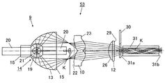
図9に示すように、プロジェクタ装置50のケース51の内部には、図示しない電源が取り付けられたプロジェクタ装置50全体を制御する電源基板52が配置されている。ケース51内の中央部付近には、電源基板52により制御される光源ユニット53が配置されている。
As shown in FIG. 9, a
図9及び図10に示すように光源ユニット53は光源9、異形レンズ10及び球面レンズ12により構成されている。図10に示すように、光源9はリフレクタ13とリフレクタ13内に収納されたランプ14により構成されている。
As shown in FIGS. 9 and 10, the
リフレクタ13の光照射用開口15から出射された光の進行方向には異形レンズ10が配置されている。異形レンズ10は光照射用開口15から出射された光を十分に集光して光の進行方向に出射できるものであれば、その形状に限定はない。
The
また、リフレクタ13には、光を出射するための光照射用開口15が設けられている。また、さらにリフレクタ13の基部にもランプ収納用開口16が設けられており、ランプ収納用開口16からランプ14が収納されている。
Further, the
図9及び図10に示すように、異形レンズ10の光の出射方向には、球面レンズ12が配置されている。球面レンズ12の出射方向には、球面レンズ12から出射された光を赤色(R)、緑色(G)、青色(B)の各色に変換するカラーホイール30が配置されている。カラーホイール30を透過した光の進行方向にはミラートンネル31が配置されており、ミラートンネル31の光の出射方向には画像をスクリーンに投影するための映像ユニット54が配置されている。なお、カラーホイール30はミラートンネル31の光の出射方向側に配置することとしてもよい。
As shown in FIGS. 9 and 10, a
図9及び図10に示すように、ミラートンネル31から光が出射される方向には映像ユニット54が配置されている。図10に示すように、映像ユニット54は、例えば、ミラートンネル31から出射された光が照射される第1集光用レンズ33、第1集光用レンズ33から出射された光が照射される第3反射用ミラー36、第3反射用ミラー36により反射された光が投射されるメニスカスレンズ39、メニスカスレンズ39から出射された光が照射されるマイクロミラー素子40、マイクロミラー素子40により反射される光が投影される投影レンズ41により構成される。
As shown in FIGS. 9 and 10, a
図9に示すように、ケース51とミラートンネル31の間には光源9を冷却するために光源9内に冷却風を流し込むシロッコファン55が配置されている。また、リフレクタ13のランプ収納用開口16された方向には光源9内に流し込まれた風をケース51内から排出するための軸流ファン56が配置されている。
As shown in FIG. 9, a sirocco fan 55 is disposed between the
ここで、本実施の形態において用いる光源ユニット53の位置関係の一例について図12を用いて説明する。なお、ここにおけるリフレクタ、ランプ及び異形レンズの寸法は、上記において例示したものを用いるものである。
Here, an example of the positional relationship of the
アーク21は光軸K上にあると共に、光軸K上であって、リフレクタ13の基部側に位置するリフレクタ13の反射面原点と光軸Kの交点Eまでの距離が5.5mmとなっている。異形レンズ10は、光源9側のレンズ面22の光軸K上に位置する中心点Xが交点Eから39.5mmの距離に位置するように配置されている。
The
また、球面レンズ12は、異形レンズ10側のレンズ面26の光軸K上に位置する中心点αが、異形レンズ10のレンズ面22の中心点Xから25.5mmの距離に位置するように配置されている。そして、ミラートンネル31は、球面レンズ12の異形レンズ10側のレンズ面26の中心点αから入射面31aと光軸K上が直行する点Hまでの距離が10.74mmとなるように配置されている。
Further, the
次に本発明の実施の形態の作用について説明する。 Next, the operation of the embodiment of the present invention will be described.
プロジェクタ装置50を駆動させると光源9のバルブ19から光が放射され、放射された光の大部分はリフレクタ13の鏡面加工が施された内壁に照射される。
When the
このとき、図11に示すように光源9のバルブ19はリフレクタ13内のランプ収納用開口16付近であって、バルブ19から放射されリフレクタ13の内壁により反射された放射光の焦点位置が異形レンズ10側の電極導入部20の先端部よりも反射光の進行方向側に形成されるように配置されているため、反射光の大部分は異形レンズ10のレンズ面22の中央部以外の部分に照射される。異形レンズ10のレンズ面22に照射された光のうち有効範囲24に照射された光は集光された後に、レンズ面23から球面レンズ12に照射される。
At this time, as shown in FIG. 11, the
球面レンズ12に照射された光は、集光された後に、カラーホイール30に照射される。
The light applied to the
カラーホイール30に照射された光は、カラーホイール30に備えられた赤色(R)、緑色(G)、青色(B)の各色のフィルタにより赤、緑、青の三色に変換された後にミラートンネル31の入射面31aに照射される。ミラートンネル31内に入射された光は、図11に示すようにミラートンネル31内の側面と外気層との界面で全反射されながら光軸方向に導かれ、出射面31bから出射された後に、図10に示すように第1集光用レンズ33に照射される。
The light applied to the
第1集光用レンズ33に照射された光は第1集光用レンズ33によりその光束が拡大された後に、第3反射用ミラー36に照射される。第3反射用ミラー36に照射された光は、メニスカスレンズ39に投射された後にマイクロミラー素子40に照射される。そして、マイクロミラー素子40により反射された光は投影レンズ41により拡大されて図示しないスクリーンに投射される。
The light applied to the
以上のように本発明によれば、バルブ19から放射されリフレクタ13により反射された放射光の焦点位置は電極導入部20にはないため、放射光の大部分はランプの電極導入部20にあたることはないため減衰することはなく、レンズに照射され放射光の損失を少なくすることができるため、光源9から放射された放射光の利用効率を高めることが可能となるためリフレクタ13を小型化することが可能となり、光源ユニット53全体を従来の光源ユニットと比較して小型化することができる。
As described above, according to the present invention, since the focal position of the radiated light emitted from the
また、光源ユニット53を小型化したためそれを搭載するプロジェクタ装置50自体を小型化することができる。また、異形レンズ10とミラートンネル31の間に球面レンズ12を配置することで、異形レンズ10から出射される光の焦点位置を調整することができ、光源ユニット53及びプロジェクタ装置50の設計の自由度を向上させることができる。
Further, since the
1 プロジェクタ装置
2 ケース
3 冷却ファン
4 吸気口
5 排気口
6 光源ユニット
9 光源
10 異形レンズ
11 第1反射用ミラー
12 球面レンズ
13 リフレクタ
14 ランプ
21 アーク
22 レンズ面
23 レンズ面
26 レンズ面
29 レンズ面
30 カラーホイール
31 ミラートンネル
33 第1集光用レンズ
34 第2反射用ミラー
35 第2集光用レンズ
36 第3反射用ミラー
39 メニスカスレンズ
40 マイクロミラー素子
41 投影レンズ
50 プロジェクタ装置
51 ケース
53 光源ユニット
54 映像ユニット
DESCRIPTION OF SYMBOLS 1
Claims (7)
前記バルブから放射された光を反射するリフレクタと、
前記バルブから放射されて前記リフレクタの内壁により反射された放射光を集光する第1のレンズと、
を備え、
前記バルブから放射されて前記リフレクタの内壁により反射された放射光は、その焦点が前記電極導入部上に位置しないように円を形成するように集光されていて、
前記第1のレンズは、
一方のレンズ面は、前記一方のレンズ面の周縁部に形成された平面部よりも中心部側に形成された膨出部、及び前記膨出部に連続して前記一方のレンズ面の中心部側に形成されていると共に中心部が窪むように形成された凹面部から形成され、
他方のレンズ面は、前記他方のレンズ面の中心部側に向かって膨出するように形成されていると共に、前記中心部が窪むように形成されている膨出部から形成されている
ことを特徴とする光源ユニット。 A light source including a bulb for emitting light and an electrode introduction portion for guiding an electrode to the bulb;
A reflector that reflects light emitted from the bulb;
A first lens that collects radiation emitted from the bulb and reflected by the inner wall of the reflector;
With
The radiated light emitted from the bulb and reflected by the inner wall of the reflector is condensed so as to form a circle so that its focal point is not located on the electrode introduction part ,
The first lens is
One lens surface is a bulging portion formed on the center side of a flat portion formed on a peripheral portion of the one lens surface, and a central portion of the one lens surface continuous to the bulging portion. It is formed from a concave surface portion that is formed on the side and formed so that the center portion is depressed,
The other lens surface is formed so as to bulge toward the center portion side of the other lens surface, and is formed from a bulging portion formed so that the center portion is recessed. > A light source unit characterized by
ことを特徴とする請求項1に記載の光源ユニット。 The focal point of the radiated light emitted from the bulb and reflected by the inner wall of the reflector is condensed such that the focal position of the radiated light is formed on the traveling direction side of the reflected light with respect to the tip of the electrode introducing portion. The light source unit according to claim 1.
前記焦点に集光後に広がる放射光が、前記第1のレンズに入射されている
ことを特徴とする請求項1又は請求項2に記載の光源ユニット。 The focal position of the radiated light emitted from the bulb and reflected by the inner wall of the reflector is located between the electrode introduction part and the first lens;
3. The light source unit according to claim 1, wherein radiant light that spreads after being condensed at the focal point is incident on the first lens. 4.
前記光源は、前記リフレクタの収納用開口から前記リフレクタ内に挿入されている
ことを特徴とする請求項1乃至請求項3の何れかに記載の光源ユニット。 The inner surface of the reflector is mirror-finished,
The light source unit according to any one of claims 1 to 3 , wherein the light source is inserted into the reflector through an opening for storing the reflector.
ことを特徴とする請求項1乃至請求項4の何れかに記載の光源ユニット。 The light source unit according to any one of claims 1 to 4, further comprising a second lens for condensing light emitted from the first lens.
前記光源ユニットから出射された光を所定の色の光に変換するカラーホイールと、
前記光源ユニットから出射された光を案内するミラートンネルと、
前記ミラートンネルから出射された光を集光する集光用レンズと、
前記集光用レンズから出射された光を受けて画像を映写するマイクロミラー素子と、
前記マイクロミラー素子から映写された画像を拡大する投影レンズと、
を備えることを特徴とするプロジェクタ装置。 A light source unit according to any one of claims 1 to 6 ,
A color wheel that converts light emitted from the light source unit into light of a predetermined color;
A mirror tunnel for guiding the light emitted from the light source unit;
A condensing lens that condenses the light emitted from the mirror tunnel;
A micromirror element that receives light emitted from the condenser lens and projects an image;
A projection lens for enlarging an image projected from the micromirror element;
A projector apparatus comprising:
Priority Applications (8)
| Application Number | Priority Date | Filing Date | Title |
|---|---|---|---|
| JP2005334141A JP4892938B2 (en) | 2005-11-18 | 2005-11-18 | Light source unit and projector device |
| CNB2006800089644A CN100572900C (en) | 2005-11-18 | 2006-10-25 | Light source cell and projecting apparatus system |
| EP06822739.6A EP1948996B1 (en) | 2005-11-18 | 2006-10-25 | Light source unit and projector system |
| KR1020077020378A KR100908952B1 (en) | 2005-11-18 | 2006-10-25 | Light source unit and projector unit |
| PCT/JP2006/321810 WO2007058070A2 (en) | 2005-11-18 | 2006-10-25 | Light source unit and projector system |
| US11/590,260 US7524088B2 (en) | 2005-11-18 | 2006-10-31 | Light source unit and projector system |
| TW095142358A TWI316639B (en) | 2005-11-18 | 2006-11-16 | Light source unit and projector system |
| HK09101051.5A HK1123345A1 (en) | 2005-11-18 | 2009-02-05 | Light source unit and projector system |
Applications Claiming Priority (1)
| Application Number | Priority Date | Filing Date | Title |
|---|---|---|---|
| JP2005334141A JP4892938B2 (en) | 2005-11-18 | 2005-11-18 | Light source unit and projector device |
Publications (3)
| Publication Number | Publication Date |
|---|---|
| JP2007140159A JP2007140159A (en) | 2007-06-07 |
| JP2007140159A5 JP2007140159A5 (en) | 2008-07-17 |
| JP4892938B2 true JP4892938B2 (en) | 2012-03-07 |
Family
ID=37983890
Family Applications (1)
| Application Number | Title | Priority Date | Filing Date |
|---|---|---|---|
| JP2005334141A Active JP4892938B2 (en) | 2005-11-18 | 2005-11-18 | Light source unit and projector device |
Country Status (8)
| Country | Link |
|---|---|
| US (1) | US7524088B2 (en) |
| EP (1) | EP1948996B1 (en) |
| JP (1) | JP4892938B2 (en) |
| KR (1) | KR100908952B1 (en) |
| CN (1) | CN100572900C (en) |
| HK (1) | HK1123345A1 (en) |
| TW (1) | TWI316639B (en) |
| WO (1) | WO2007058070A2 (en) |
Families Citing this family (4)
| Publication number | Priority date | Publication date | Assignee | Title |
|---|---|---|---|---|
| JP3912407B2 (en) * | 2004-12-14 | 2007-05-09 | カシオ計算機株式会社 | Light source unit and projector device |
| JP4218649B2 (en) * | 2005-03-07 | 2009-02-04 | カシオ計算機株式会社 | Light source unit and projector device |
| CN102395546B (en) * | 2009-03-12 | 2014-03-12 | 拜耳作物科学公司 | Method for producing aromatic chlorine and bromine compounds |
| JP6867584B2 (en) * | 2017-03-30 | 2021-04-28 | 株式会社今仙電機製作所 | Vehicle lighting |
Family Cites Families (17)
| Publication number | Priority date | Publication date | Assignee | Title |
|---|---|---|---|---|
| DE3228531A1 (en) * | 1982-07-30 | 1984-02-02 | Patent-Treuhand-Gesellschaft für elektrische Glühlampen mbH, 8000 München | Illuminating system consisting of a halogen ellipsoid reflector lamp having a lens downstream of the lamp and a heat absorption filter |
| US4642740A (en) * | 1984-10-22 | 1987-02-10 | General Electric Company | Constant magnification light collection system |
| EP0198676A3 (en) * | 1985-04-12 | 1988-10-12 | Oscar Moreno Gil | Bicurve lenses |
| ES8604355A1 (en) * | 1985-04-12 | 1986-02-01 | Moreno Gil Oscar | Double curved lens |
| JP3132020B2 (en) * | 1991-02-22 | 2001-02-05 | セイコーエプソン株式会社 | Light source device and projection display device using the same |
| US5335044A (en) * | 1992-02-26 | 1994-08-02 | Nikon Corporation | Projection type exposure apparatus and method of exposure |
| JPH0651401A (en) | 1992-07-27 | 1994-02-25 | Fujitsu General Ltd | Light source device for projector |
| FR2706017B1 (en) * | 1993-06-04 | 1995-08-25 | Valeo Vision | Motor vehicle projector with adjustable lighting. |
| JP3508190B2 (en) * | 1993-12-21 | 2004-03-22 | セイコーエプソン株式会社 | Lighting device and projection display device |
| JP4023066B2 (en) * | 1999-04-02 | 2007-12-19 | セイコーエプソン株式会社 | Light source device, and illumination optical system and projector including the same |
| JP2002049096A (en) * | 2000-08-01 | 2002-02-15 | Mitsubishi Electric Corp | Light condensing optical system and projection type display device using the same |
| JP3738691B2 (en) * | 2001-01-05 | 2006-01-25 | セイコーエプソン株式会社 | Light modulation device position adjustment device, light modulation device position adjustment method, and initial position adjustment jig |
| JP2002214563A (en) * | 2001-01-12 | 2002-07-31 | Mitsubishi Electric Corp | Lamp, polarization converting optical system, condensing optical system and picture display device |
| JP4722312B2 (en) * | 2001-03-30 | 2011-07-13 | 三菱電機株式会社 | Lamp, condensing optical system, and image display device |
| JP2002350778A (en) * | 2001-05-24 | 2002-12-04 | Seiko Epson Corp | Illumination optical system and projector equipped with the system |
| JP2003295312A (en) * | 2002-04-02 | 2003-10-15 | Mitsubishi Electric Corp | Light irradiation device and projection type image display device |
| JP4622285B2 (en) * | 2004-03-26 | 2011-02-02 | カシオ計算機株式会社 | LIGHT SOURCE DEVICE AND PROJECTOR HAVING THE SAME |
-
2005
- 2005-11-18 JP JP2005334141A patent/JP4892938B2/en active Active
-
2006
- 2006-10-25 EP EP06822739.6A patent/EP1948996B1/en active Active
- 2006-10-25 KR KR1020077020378A patent/KR100908952B1/en active IP Right Grant
- 2006-10-25 WO PCT/JP2006/321810 patent/WO2007058070A2/en active Application Filing
- 2006-10-25 CN CNB2006800089644A patent/CN100572900C/en active Active
- 2006-10-31 US US11/590,260 patent/US7524088B2/en active Active
- 2006-11-16 TW TW095142358A patent/TWI316639B/en not_active IP Right Cessation
-
2009
- 2009-02-05 HK HK09101051.5A patent/HK1123345A1/en not_active IP Right Cessation
Also Published As
| Publication number | Publication date |
|---|---|
| KR20070103769A (en) | 2007-10-24 |
| HK1123345A1 (en) | 2009-06-12 |
| KR100908952B1 (en) | 2009-07-22 |
| WO2007058070A3 (en) | 2007-10-25 |
| WO2007058070A2 (en) | 2007-05-24 |
| EP1948996B1 (en) | 2013-05-22 |
| TWI316639B (en) | 2009-11-01 |
| US7524088B2 (en) | 2009-04-28 |
| CN100572900C (en) | 2009-12-23 |
| JP2007140159A (en) | 2007-06-07 |
| CN101238327A (en) | 2008-08-06 |
| EP1948996A2 (en) | 2008-07-30 |
| TW200727069A (en) | 2007-07-16 |
| US20070115664A1 (en) | 2007-05-24 |
Similar Documents
| Publication | Publication Date | Title |
|---|---|---|
| JP6236891B2 (en) | Light source device and image display device | |
| JP5429543B2 (en) | Light source unit and projector | |
| JP2005173019A (en) | Light source device and projector with the same | |
| JP4218649B2 (en) | Light source unit and projector device | |
| JP4892938B2 (en) | Light source unit and projector device | |
| JP2018200490A (en) | Light source apparatus and image display apparatus | |
| JP2005274836A (en) | Illuminating light source device | |
| TWI296068B (en) | Light source unit and projector system | |
| JP2005283918A (en) | Light source device for illumination | |
| JP2016118604A (en) | Rotary optical element device, luminaire, and image projection apparatus | |
| JP2005283613A (en) | Light source device and projector equipped therewith | |
| JP4225055B2 (en) | Light source device and projector using the same | |
| JP4329660B2 (en) | Light source device and projector | |
| JP2006106357A (en) | Light source unit and projector | |
| JP2006258895A (en) | Light source unit and projector | |
| JP2007227690A (en) | Reflector, and light-emitting module using it | |
| JP2012118230A (en) | Projection type video display device |
Legal Events
| Date | Code | Title | Description |
|---|---|---|---|
| A521 | Request for written amendment filed |
Free format text: JAPANESE INTERMEDIATE CODE: A523 Effective date: 20080530 |
|
| A621 | Written request for application examination |
Free format text: JAPANESE INTERMEDIATE CODE: A621 Effective date: 20080530 |
|
| A131 | Notification of reasons for refusal |
Free format text: JAPANESE INTERMEDIATE CODE: A131 Effective date: 20110329 |
|
| A521 | Request for written amendment filed |
Free format text: JAPANESE INTERMEDIATE CODE: A523 Effective date: 20110526 |
|
| RD02 | Notification of acceptance of power of attorney |
Free format text: JAPANESE INTERMEDIATE CODE: A7422 Effective date: 20110526 |
|
| A131 | Notification of reasons for refusal |
Free format text: JAPANESE INTERMEDIATE CODE: A131 Effective date: 20110802 |
|
| A521 | Request for written amendment filed |
Free format text: JAPANESE INTERMEDIATE CODE: A523 Effective date: 20110909 |
|
| TRDD | Decision of grant or rejection written | ||
| A01 | Written decision to grant a patent or to grant a registration (utility model) |
Free format text: JAPANESE INTERMEDIATE CODE: A01 Effective date: 20111122 |
|
| A01 | Written decision to grant a patent or to grant a registration (utility model) |
Free format text: JAPANESE INTERMEDIATE CODE: A01 |
|
| A61 | First payment of annual fees (during grant procedure) |
Free format text: JAPANESE INTERMEDIATE CODE: A61 Effective date: 20111205 |
|
| R150 | Certificate of patent or registration of utility model |
Ref document number: 4892938 Country of ref document: JP Free format text: JAPANESE INTERMEDIATE CODE: R150 Free format text: JAPANESE INTERMEDIATE CODE: R150 |
|
| FPAY | Renewal fee payment (event date is renewal date of database) |
Free format text: PAYMENT UNTIL: 20150106 Year of fee payment: 3 |