JP4889033B2 - furniture - Google Patents
furniture Download PDFInfo
- Publication number
- JP4889033B2 JP4889033B2 JP2007080746A JP2007080746A JP4889033B2 JP 4889033 B2 JP4889033 B2 JP 4889033B2 JP 2007080746 A JP2007080746 A JP 2007080746A JP 2007080746 A JP2007080746 A JP 2007080746A JP 4889033 B2 JP4889033 B2 JP 4889033B2
- Authority
- JP
- Japan
- Prior art keywords
- drawer
- thickness
- locking
- elastic
- housing
- Prior art date
- Legal status (The legal status is an assumption and is not a legal conclusion. Google has not performed a legal analysis and makes no representation as to the accuracy of the status listed.)
- Expired - Fee Related
Links
Images


Landscapes
- Drawers Of Furniture (AREA)
Description
本発明は、多段状に抽斗を有する家具に関する。 The present invention relates to furniture having drawers in multiple stages.
ワゴンやキャビネットには施錠装置を設けることが一般的である。最近、意匠上の観点等から、筐体の框幅を細く形成したキャビネット等の家具が販売されている。こうした狭い幅の框には施錠ブロック部を設けることは不可能である。こうしたことのため、それを抽斗に設けることが行われる。抽斗に施錠ブロック部の設けられた家具の例が下記特許文献1に開示されている。
施錠装置の施錠ブロック部に鍵を挿入して施錠操作をして施錠用の係止部材を作動させた際に、施錠ブロック部は該施錠装置の機構に組み込まれているコイルバネ等の弾性部材の付勢力反力を受ける。従って、施錠ブロック部を特定抽斗に設けた場合は、この特定抽斗自体が前記の弾性部材の反力を受ける。従って、特定抽斗がその反力方向に押される。このため他の抽斗とは抽斗の側面ラインが揃わなくなることがあり、美観上好ましくない。
そこで本発明は、多段状の抽斗が精度良く上下方向に整列する構造の家具を提供する。更には、筐体の框と抽斗の左右の隙間をできるだけ同じにできる家具を提供する。
When a locking member for locking is operated by inserting a key into the locking block portion of the locking device and operating the locking member, the locking block portion is an elastic member such as a coil spring incorporated in the mechanism of the locking device. Receives an urging reaction. Therefore, when the locking block portion is provided in the specific drawer, the specific drawer itself receives the reaction force of the elastic member. Accordingly, the specific drawer is pushed in the reaction force direction. For this reason, the side lines of the drawers may not be aligned with other drawers, which is not desirable from an aesthetic point of view.
Therefore, the present invention provides a furniture having a structure in which multistage drawers are accurately aligned in the vertical direction. Furthermore, the furniture which can make the clearance gap of a housing | casing and the left and right of a drawer the same as possible is provided.
第1の発明では、抽斗が多段状に配設された家具であって、施錠装置の施錠ブロック部が特定の抽斗の前面部に設けられており、施錠操作によって弾性部材の付勢力に抗しつつ左右の何れか一方向に移動することで施錠用の係止部材を作動させる左右移動材を有し、各抽斗の前面部の左側面又は右側面に対面する筐体の左右の内面側であって、前記一方向の側の筐体内面側には、抽斗前面部の側面を付勢する弾力性サイド部品を設けていることを特徴とする家具を提供する。 In the first invention, the drawer is a furniture in which the drawers are arranged in a multistage shape, and the locking block portion of the locking device is provided on the front surface portion of the specific drawer, and resists the biasing force of the elastic member by the locking operation. On the left and right inner surfaces of the housing facing the left side or right side of the front part of each drawer, it has a left and right moving material that operates the locking member by moving in either one of the left and right directions The furniture is characterized in that an elastic side part for urging the side surface of the front surface of the drawer is provided on the inner surface side of the casing in the one direction.
第2の発明では、第1の発明の筐体の左右内面の内の前記弾力性サイド部品を設ける側とは反対側には、夫々、前記弾力性サイド部品をその弾力性に抗して完全に押し付けた際の厚さと同じ厚さTを有する定厚サイド部品を設けており、各抽斗前面部の左右側面と、該左右側面の対面する筐体左右内面との左右の各隙間を同じ値に振り分けた場合のその隙間寸法をΔとすれば、0.85・Δ≦T<Δの関係になるように、両種類のサイド部品は前記隙間寸法Δに近い厚さTを有しているよう構成する。好ましくは、0.9・Δ≦T<Δである。 In the second aspect of the invention, the elastic side parts are completely opposed to the elastic side parts on the opposite side of the left and right inner surfaces of the casing of the first aspect of the casing. Constant thickness side parts having the same thickness T as the thickness when pressed against the left and right sides of the left and right side surfaces of the front of each drawer and the left and right inner surfaces of the housing facing each other are the same value If the gap dimension when the distribution is divided into Δ is Δ, both types of side parts have a thickness T close to the gap dimension Δ so that a relationship of 0.85 · Δ ≦ T <Δ is satisfied. Configure as follows. Preferably, 0.9 · Δ ≦ T <Δ.
第1の発明では、施錠装置の施錠ブロック部が特定の抽斗の前面部に設けられており、施錠操作によって左右移動材を弾性部材の付勢力に抗しつつ左右何れか一方向に移動させて係止部材を作動させるため、この特定抽斗は前記一方向とは逆方向に付勢される。このため、付勢力を受けない他の抽斗とは抽斗前面部の側面ラインが揃わない。これを防止するため、該他の抽斗の前面部に対面する筐体の左右内面側であって、前記一方向の側の筐体内面側に弾力性サイド部品を設ける。開錠状態では前記特定抽斗は弾性部材の付勢力を受けることはなく、もし、該特定抽斗の前記一方向の側の筐体内面側に弾力性サイド部品を装着していなければ、該特定抽斗が該一方向の側に偏ることがある。これを防止するため、この特定抽斗の前面部側面と対面する前記一方向の側の筐体内面側にも他の抽斗に対応するものと同じ弾力性サイド部品を装着させる。 In the first invention, the locking block portion of the locking device is provided on the front surface portion of the specific drawer, and the right and left moving material is moved in either the left or right direction against the urging force of the elastic member by the locking operation. In order to operate the locking member, the specific drawer is biased in the direction opposite to the one direction. For this reason, the side line of the front part of the drawer does not align with other drawers that do not receive the urging force. In order to prevent this, elastic side parts are provided on the left and right inner surfaces of the housing facing the front surface of the other drawer, on the inner surface of the housing in the one direction. In the unlocked state, the specific drawer does not receive the urging force of the elastic member. If no elastic side part is attached to the inner surface of the casing on the one-direction side of the specific drawer, the specific drawer May be biased toward the one direction. In order to prevent this, the same elastic side parts as those corresponding to the other drawers are mounted on the inner surface of the casing in the one direction facing the side surface of the front surface of the specific drawer.
第2の発明では、第1の発明のように抽斗前面部の側面ラインが揃うのみならず、各抽斗左右と筐体框部との間の隙間を可及的に同じに設定することが可能となる。即ち、所定の押圧条件の弾力性サイド部品も定厚サイド部品も同じ厚さであり、この厚さTを各抽斗左右と筐体框部との間の設定隙間Δの90%程度(85%以上100%未満)に設定することにより、左右の実隙間の差を小さくできる(殆ど同じ値にすることができる)。 In the second invention, not only the side lines of the front surface of the drawer are aligned as in the first invention, but also the gap between the left and right of each drawer and the housing collar can be set as much as possible. It becomes. That is, the elastic side part and the constant-thickness side part under a predetermined pressing condition have the same thickness, and this thickness T is about 90% (85%) of the set gap Δ between the left and right of each drawer and the casing collar. By setting it to less than 100%, the difference between the left and right actual gaps can be reduced (can be set to almost the same value).
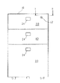
図1は本発明に係る家具の例としてのワゴン型の3段キャビネットの正面図である。各抽斗20,40,60は、その収納状態において常時前方に押し出す付勢力が作用する構造となっている。その具体例として、図2には最上段の抽斗20の後部に装着した付勢機構を模式的に図示しているが、他の抽斗も同様である。抽斗後部側面の外側或いは内側に固定したケース70に対して進退棒72を前後方向に貫通させている。この進退棒に固定された鍔部73とケース端面との間にコイルスプリング76が配設されている。進退棒72の後端部にはゴム製端部部材74が設けられており、抽斗20を収納した際に、部材74が筐体10の後部内面等に当接、押圧することで、進退棒72が矢印方向(前方向)に移動し、コイルスプリング76が圧縮される。この付勢力によって抽斗20を押し出す力が作用する。他の抽斗も同様である。
FIG. 1 is a front view of a wagon type three-stage cabinet as an example of furniture according to the present invention. Each of the
図4は引手によるラッチ部品の係脱機構(ラッチ機構)の斜視図であり、図6は図1の矢視線F−Fによる拡大断面図であり、一部簡略化している。各抽斗には図4や図6に示すラッチ部品34をラッチ掛具36に係脱させるための引手24が設けられており、この実施例ではプッシュ式の引手を採用している。抽斗20の前部の縦断面図を図3に示す。前面部22の前面板には適宜な位置に開口22Kを設けており、この開口に嵌っている引手24を指で押す。そうすると、図3に示すように引手24は蝶番の軸26を枢軸として後方から支持しているコイルスプリング等のばね部材31の付勢力に抗しつつ回動して後方に傾斜する。ばね部材31と引手の間には介在部材28が介在している。この介在部材の下方部に、該介在部材が固定装着されている水平軸30が水平状態で、その中心軸線30J回りに回転可能に軸受されている。従って引手24を押すことによって水平軸30が矢印方向に回転し、該水平軸の端部が概ね下方に向かってL字状に折れ曲がった軸端部30Eが、前記中心軸線30Jを中心として矢印の方向に回動する。
4 is a perspective view of a latch part engaging / disengaging mechanism (latch mechanism) by a pull handle, and FIG. 6 is an enlarged cross-sectional view taken along line FF in FIG. 1 and is partially simplified. Each drawer is provided with a
図4を参照すると、前記水平軸30とラッチ部品34との間には、その中心軸線32Jを中心として回転可能に軸受された上下方向軸32が介在しており、その上端部はラッチ部品34に固定されている。この上下方向軸の下端部は水平方向にL字状に折れ曲がった軸端部32Eに形成されている。従って、前記軸端部30Eの中心軸線30Jを中心とした回動によって、この軸端部32Eが中心軸線32Jを中心として、矢印の方向に回動する。その結果、ラッチ部品34は矢印の方向に回動し、ラッチ掛具36との係合が外れる。また、上下方向軸かラッチ部品には、図示を省略しているばね部材によって、常時、ラッチ掛具に係合する方向(図4のラッチ部品の矢印とは逆の方向)の付勢力が作用している。
Referring to FIG. 4, a
図5は施錠装置の施錠ブロック部12近くの拡大正面図であり、施錠ブロック部12はこの例では最上段の抽斗20に設けられているが、他の抽斗40,60に設けられていてもよい。施錠ブロック部12の後部には、鍵の施錠又は開錠操作によって施錠ブロックの中心回りに回動するピン軸部14が設けられている。また、このピン軸部が係合する凹部16Kを有する左右移動材としての左右移動板部材16が左右方向にのみ移動可能に配設されている。図5に示す矢印は施錠操作時の方向であり、鍵を施錠操作すると前記ピン軸部14が左右移動板部材16を右方向に押しつつ矢印方向(時計回り方向)に回動移動する。その移動結果位置を14’で示している。即ち、左右移動板部材はその分だけ右に移動する。
FIG. 5 is an enlarged front view near the
図6を参照すると、筐体10の内側であって、抽斗側板との間の空間に、中心軸線40Jを中心として回転可能であって、上下方向に延伸した鍵棒40が配設されている。この鍵棒と共に回転するようレバー42が設けられており、開錠状態における左右移動板部材16の端部(図6の右側)近くにレバー端部が位置している。また、係止部材として、図6に示す形状のL字形の鍵板44が鍵棒と共に回動するように鍵棒に対して固定されている。
Referring to FIG. 6, a
施錠操作によって前記左右移動板部材16が図6の右方向に駆動させる場合、コイルスプリング18の付勢力に抗してレバー42の端部を右方向に移動させる。即ち、レバー42は中心軸線40Jの回りに回動する。従って、鍵棒40が回転し、これと共に鍵板44が回動する。施錠を行うと、鍵板44は2点鎖線44’で示す位置に来る。この位置の鍵板は、ラッチ掛具36に係合しているラッチ部品34の図6における左側を押さえる状態に係止する。これによって、施錠状態の場合、引手24を押そうとしても、ラッチ部品34がラッチ掛具36から外れない。従って、仮に鍵板の係止がこのラッチ部品に対してではなく、抽斗側部の凸部に係止する構造の場合、この凸部と鍵板とに存在し得る隙間分、図2に示す付勢機構の作用によって抽斗が前方に押し出され、これによって、ラッチ部品がラッチ掛具との係合状態に復帰できない事態が生じ得るが、本実施例構造ではこれを防止できる。
When the left / right moving
開錠操作をすれば、左右移動板部材16が左方向に移動するため、ばね18の付勢力の作用によって鍵板44は図6の実線で示す開放位置に復帰する。また、鍵棒40は2段目の抽斗40と3段目の抽斗60の側面部にまで至っており、夫々の抽斗に設けたラッチ部品34の高さ部分の鍵棒に同様の鍵板44が固定されている。
If the unlocking operation is performed, the left and right moving
施錠時の左右移動板部材による力や、鍵板44がラッチ部品34に係止した場合に受ける力、或いは、この係止状態(施錠状態)において(誤って)引手24を操作しようとする力等の力に起因する曲げ作用をする力を鍵棒40は受ける。従って、この鍵棒の曲がり(撓み)を防止するため、鍵棒受け37を、夫々の抽斗に対応する各鍵板の固定位置(ラッチ部品の高さ位置)の鍵棒を取り囲むように夫々配設している。この鍵棒受け37は樹脂の射出成形品としてラッチ掛具36と一体に形成している。この一体部品38の平面視概略形状は、ラッチ掛具36の部分が略三角形状であり、鍵棒受け37の部分が略矩形状である。装着手法は、筐体10の前部構造と関係があるため、まず筐体前部構造を説明する。
The force by the left and right moving plate member at the time of locking, the force received when the
この例での筐体10の前部構造は、図6に平面視を図示しているように、筐体の側板を前端部で内方に向かって折り曲げた第1折曲部10Aを有し、この第1折曲部を左右方向内側に向かって(図6では左方向に)折り曲げて第2折曲部10Bを有し、この第2折曲部を後方に向かって筐体側板と平行になるよう折り曲げた第3折曲部10Cを有し、更に、この第3折曲部を筐体の側板外方向に向けて折り曲げた、幅(折り曲げ方向長さ)の狭い第4折曲部10Dを有している。この筐体側板には、少なくとも前部では、別部品である補強用フレーム部材等を溶接等で一体化させてはいない。そのため、前記一体部品38を筐体10に保持固定させるには前記の各折曲部を利用している。
The front structure of the
前記第3折曲部10Cには適宜な位置と大きさの貫通孔を形成しており、ここに、ラッチ掛具36における、筐体側板に向かう面に設けた係合凸部36Kを挿入係止させる。一方、第4折曲部10Dの端面と筐体側板との間隙に鍵棒受け37の前側部を挿入して間隙を埋め、鍵棒受け37の筐体側板側の面が筐体側板内面に当接している。これにより、一体部品38が筐体10に対して固定されると共に、鍵棒40の撓みが防止される。従って、鍵板44によるラッチ部品への係止が信頼性高く可能となる。また、ラッチ掛具36と鍵棒受け37とを一体にしたため、部品点数が減少し、コスト低減に寄与する。
A through hole having an appropriate position and size is formed in the third
上記図6の説明から判るが、筐体10の框の幅は筐体の側板とその折り返し部である第1折曲部10Aとを併せた程度の厚さ寸法であり、この例では2.5mmという細さである。従って、施錠装置の施錠ブロック部12をこの框部に設けることは実質的に不可能である。このため、この例では最上段の抽斗20に設けているが、第1の発明に関しては、施錠ブロック部は框部に設けていてもよい。また、この框と抽斗の前面部の左右側面(22A等)との成す隙間は、左右の各隙間を同じ値に振り分けた場合のその設定隙間をΔとすれば、Δ=1.5mmとしている。3個の抽斗の上下方向の整列状態、即ち、抽斗前面部の側面ラインができるだけ揃うようにしたい。また、左右の現実の隙間をできるだけ同じにしたい。このために、この実施形態例では、各抽斗に対応する右側框部の内側面には、図7に示す弾力性サイド部品50を装着させ、左側框部の内側面には、図示しない定厚サイド部品を装着させる。
As can be seen from the description of FIG. 6 above, the width of the ridge of the
上記したように、右側に弾力性サイド部品を設けるのは、この例では、施錠時に既述の左右移動板部材16が右方向に駆動されるからである。即ち、コイルスプリング18の付勢力に抗しつつ駆動されるため、抽斗20はその反力としてこの左右移動板部材16を介して左方向に押される。然しながら、他の抽斗40,60には施錠ブロック部12と左右移動板部材16は設けられていないため、こうした反力を受けることがない。このため、最上段の抽斗20のみが左側に偏位することになり、抽斗前面部の側面ラインが揃わない。これを防止するために、2段目と3段目の各抽斗も左方向に付勢されるようにしたい。このため、2段目と3段目の各抽斗の前面部右側面に対面する筐体内面、即ち、框部の内側面(第1折曲部10Aの抽斗側の面)に弾力性サイド部品50を装着させる。この弾力性サイド部品によって各抽斗は左方向に付勢されている。
As described above, the elastic side part is provided on the right side in this example because the aforementioned left and right moving
しかし、開錠状態では、抽斗20にはコイルスプリング18による左方向への付勢力は作用しない。このため、他の抽斗40,60にのみ左方向への付勢力を作用させる構造では、やはり、抽斗前面部の側面ラインが揃わない。そこで、施錠ブロック部を設けている抽斗20に対しても他の抽斗40,60と同じ作用をする同じ弾力性サイド部品50を、抽斗20の前面部22の右側面22Aに対面する筐体内面に設ける。
However, in the unlocked state, the leftward biasing force by the
これでいつも抽斗前面部の側面ラインが揃う。しかし、これだけでは、抽斗の左側の隙間と右側の隙間の各大きさは異なってしまい、右側隙間が大きくなる。そこで、定厚サイド部品を、弾力性サイド部品に対応する左側框部の内側面に装着させる。以下、これらのサイド部品につき、図7を参照しつつ説明する。また、これらの両種類のサイド部品は抽斗前面部の側面が当接しつつ擦ることを前提としており、抽斗の傷つき防止等の観点から樹脂製としている。 This always aligns the side lines on the front of the drawer. However, with this alone, the sizes of the left and right gaps of the drawer differ, and the right gap becomes larger. Therefore, the constant-thickness side part is attached to the inner side surface of the left side collar corresponding to the elastic side part. Hereinafter, these side parts will be described with reference to FIG. These two types of side parts are premised on rubbing while the side surfaces of the front face of the drawer are in contact with each other, and are made of resin from the viewpoint of preventing damage to the drawer.
図7(a)に示すように、平面視が矩形状を成しており、中央の立壁部52の右側部58は図6に示すように第2折曲部10Bに設けたスリット状の貫通孔10BKを通して内部側に挿入させる部位である。その幅方向中央部であって、厚さ方向に弾力性のある爪部60によって貫通孔10BKから前方への抜け止めを果たす。また、この爪部前端面と前記立壁部52とによって第2折曲部10Bを挟持すると共に、この右側部58の後端縁部(図7の右端縁部)は筐体側面の内壁面に当接しており、これらが部品50の装着固定の作用を成す。
As shown in FIG. 7A, the plan view has a rectangular shape, and the
部品50の図7の左側部は、その幅方向中央部の厚さ方向に弾力性のある爪部56と、これを挟む位置に定厚部54が形成されている。また、この定厚部も爪部も、その前側部分(図7の左側部分)54T,56Tは板厚が前端から後方に漸増する傾斜状に形成されている。定厚部54の板厚Tはこの例では、1.4mmであり、力の作用していない状態での爪部56の上面までの高さTMは、この例では2mmである。爪部56を弾力性に抗して所定以上の力で押せば、この部品50の図7の左側部としての厚さは定厚部板厚Tとなる。
The left side of the
図示しない定厚サイド部品は、図7(b)の爪部56(と56T)の無い部品であり、(a)では、爪部56を区画形成しているコ字状の切り込み貫通穴が無く、爪部に相当する領域は定厚部54と同じにできている。従って、その厚さは前記の板厚Tと同じである。定厚サイド部品の右側部は図7のものと同じである。従って、普段、各抽斗20,40,60は左側に付勢されているため、定厚サイド部品に当接している。即ち、筐体との抽斗左側隙間は定厚サイド部品の厚さT=1.4mmである。一方、右側隙間は、既述の通り左右の設定隙間Δは1.5mmであるため、1.5mm×2−1.4mm=1.6mmである。0.85・Δ≦T<Δの関係になるほど両種類のサイド部品は前記設定隙間Δに近い厚さTを有しており、少なくともこの厚さT分の隙間を確保でき、設定隙間Δに近い値の隙間となる。従って、左右の隙間の相違は小さくなる。
A constant-thickness side part (not shown) is a part without the claw portion 56 (and 56T) of FIG. 7B. In FIG. 7A, there is no U-shaped cut through hole that defines the
弾力性サイド部品は図7の形態に限られず、板厚方向の厚さ寸法を弾力的に変化させる構造が種々考えられる。例えば、図7の立壁部52の左側部において、定厚部54の下面側の側面視を、その中央部が上方に位置する弓形状にし、爪部56の存在を不要とした樹脂部品としてもよい。
The elastic side parts are not limited to the form shown in FIG. 7, and various structures for elastically changing the thickness dimension in the plate thickness direction are conceivable. For example, in the left side portion of the standing
図6に示す機構では、左右移動板部材16は施錠時に右方向に駆動される構造であるが、家具の左側にラッチ機構や鍵棒や鍵板を配設して、左右移動板部材を左方向に駆動させる構造としてもよい。この場合は、左側に弾力性サイド部品を装着させ、右側に定厚サイド部品を装着させる。
In the mechanism shown in FIG. 6, the left and right moving
また、ラッチ部品34を作動させるラッチ機構や施錠装置の具体的構造は、本実施形態例のものに限定されない。図2に示すような抽斗に装着した付勢機構が無く、また、係止部材としての鍵板44の係止相手がラッチ部品34ではなく、抽斗側面に設ける凸部であってもよく、鍵棒40は、回転する構造ではなく上下に移動するものでもよい。但し、施錠や開錠の操作時に弾性部材(コイルスプリング18)の付勢力に抗して左右の何れかの方向に移動する左右移動材に相当する部材は必要である。また、筐体10の框が本実施例のように薄い構造の家具に限らず、従来のように幅の広いものであっても、施錠ブロック部が特定抽斗に設けられていればよい。家具としては、ワゴンではなく、設置型のキャビネット等でもよい。
Further, the specific structure of the latch mechanism and the locking device that actuate the
本発明は、抽斗を有するワゴンやキャビネット等の家具に利用できる。 The present invention can be used for furniture such as a wagon or cabinet having a drawer.
10 筐体
12 施錠ブロック部
16 左右移動板部材
20,40,60 抽斗
24 プッシュ式引手
34 ラッチ部品
36 ラッチ掛具
37 鍵棒受け
40 鍵棒
44 鍵板
50 弾力性サイド部品
DESCRIPTION OF
Claims (2)
施錠装置の施錠ブロック部(12)が特定の抽斗(20)の前面部(22)に設けられており、施錠操作によって弾性部材(18)の付勢力に抗しつつ左右の何れか一方向に移動することで施錠用の係止部材(44)を作動させる左右移動材(16)を有し、
各抽斗の前面部の左側面又は右側面(22A)に対面する筐体の左右の内面側であって、前記一方向の側の筐体内面(10A)側には、抽斗前面部の側面を付勢する弾力性サイド部品(50)を設けている
ことを特徴とする家具。 It is furniture with drawers arranged in multiple stages,
The locking block portion (12) of the locking device is provided on the front surface portion (22) of the specific drawer (20), and resists the urging force of the elastic member (18) by the locking operation in either the left or right direction. It has a left and right moving member (16) that operates a locking member (44) for locking by moving,
The left and right inner surfaces of the casing facing the left side or right side (22A) of the front portion of each drawer, and the side surface of the drawer front portion on the casing inner surface (10A) side of the one direction side Furniture characterized by providing elastic side parts (50) for biasing.
Priority Applications (1)
| Application Number | Priority Date | Filing Date | Title |
|---|---|---|---|
| JP2007080746A JP4889033B2 (en) | 2007-03-27 | 2007-03-27 | furniture |
Applications Claiming Priority (1)
| Application Number | Priority Date | Filing Date | Title |
|---|---|---|---|
| JP2007080746A JP4889033B2 (en) | 2007-03-27 | 2007-03-27 | furniture |
Publications (2)
| Publication Number | Publication Date |
|---|---|
| JP2008237448A JP2008237448A (en) | 2008-10-09 |
| JP4889033B2 true JP4889033B2 (en) | 2012-02-29 |
Family
ID=39909497
Family Applications (1)
| Application Number | Title | Priority Date | Filing Date |
|---|---|---|---|
| JP2007080746A Expired - Fee Related JP4889033B2 (en) | 2007-03-27 | 2007-03-27 | furniture |
Country Status (1)
| Country | Link |
|---|---|
| JP (1) | JP4889033B2 (en) |
Families Citing this family (1)
| Publication number | Priority date | Publication date | Assignee | Title |
|---|---|---|---|---|
| CN105815952B (en) * | 2016-05-10 | 2018-03-16 | 平湖台丽办公自动化设备有限公司 | A kind of drawer panel locking device |
Family Cites Families (3)
| Publication number | Priority date | Publication date | Assignee | Title |
|---|---|---|---|---|
| JPS4420832Y1 (en) * | 1965-12-07 | 1969-09-05 | ||
| JP4658413B2 (en) * | 2001-09-21 | 2011-03-23 | 株式会社岡村製作所 | Storage and unlocking device for storage |
| JP4706039B2 (en) * | 2005-06-24 | 2011-06-22 | コクヨ株式会社 | Drawer lock mechanism |
-
2007
- 2007-03-27 JP JP2007080746A patent/JP4889033B2/en not_active Expired - Fee Related
Also Published As
| Publication number | Publication date |
|---|---|
| JP2008237448A (en) | 2008-10-09 |
Similar Documents
| Publication | Publication Date | Title |
|---|---|---|
| JPWO2006030610A1 (en) | Lid opening / closing device | |
| CN101923884A (en) | Hard-disk extracting device and electronic device using the same | |
| WO2010069105A1 (en) | Lock-on switch system for hand drill and hand drill having the same | |
| JP5109624B2 (en) | Door, rack | |
| JP5164671B2 (en) | Vehicle seat slide device | |
| JP4889033B2 (en) | furniture | |
| JP4931663B2 (en) | furniture | |
| JP5789438B2 (en) | Latch device | |
| JP2017087929A (en) | Seat lock device | |
| JP4080760B2 (en) | Door handle device | |
| EP3886546B1 (en) | Slide rail assembly | |
| JP4430469B2 (en) | Latch device | |
| JP4098168B2 (en) | Card connector | |
| JP4823808B2 (en) | Drawer latch device | |
| JP2000288214A (en) | Locking device for game machine | |
| US7946462B2 (en) | Electric stapler | |
| JP5800201B2 (en) | Side lock device | |
| JP2009146603A (en) | Connector | |
| CN211529822U (en) | Push-button switch | |
| JP6089299B2 (en) | Door latch device for automobile | |
| JP2012030694A (en) | Seat sliding device for vehicle | |
| JP5132942B2 (en) | cabinet | |
| JP5954121B2 (en) | Side lock device | |
| KR100924871B1 (en) | Quick connection terminal device | |
| JP5154287B2 (en) | Vibration lock device |
Legal Events
| Date | Code | Title | Description |
|---|---|---|---|
| A621 | Written request for application examination |
Free format text: JAPANESE INTERMEDIATE CODE: A621 Effective date: 20100215 |
|
| A977 | Report on retrieval |
Free format text: JAPANESE INTERMEDIATE CODE: A971007 Effective date: 20111207 |
|
| TRDD | Decision of grant or rejection written | ||
| A01 | Written decision to grant a patent or to grant a registration (utility model) |
Free format text: JAPANESE INTERMEDIATE CODE: A01 Effective date: 20111209 |
|
| A01 | Written decision to grant a patent or to grant a registration (utility model) |
Free format text: JAPANESE INTERMEDIATE CODE: A01 |
|
| A61 | First payment of annual fees (during grant procedure) |
Free format text: JAPANESE INTERMEDIATE CODE: A61 Effective date: 20111209 |
|
| R150 | Certificate of patent or registration of utility model |
Free format text: JAPANESE INTERMEDIATE CODE: R150 |
|
| FPAY | Renewal fee payment (event date is renewal date of database) |
Free format text: PAYMENT UNTIL: 20141222 Year of fee payment: 3 |
|
| S531 | Written request for registration of change of domicile |
Free format text: JAPANESE INTERMEDIATE CODE: R313531 |
|
| R360 | Written notification for declining of transfer of rights |
Free format text: JAPANESE INTERMEDIATE CODE: R360 |
|
| R370 | Written measure of declining of transfer procedure |
Free format text: JAPANESE INTERMEDIATE CODE: R370 |
|
| S531 | Written request for registration of change of domicile |
Free format text: JAPANESE INTERMEDIATE CODE: R313531 |
|
| R350 | Written notification of registration of transfer |
Free format text: JAPANESE INTERMEDIATE CODE: R350 |
|
| R250 | Receipt of annual fees |
Free format text: JAPANESE INTERMEDIATE CODE: R250 |
|
| LAPS | Cancellation because of no payment of annual fees |