JP4885269B2 - Heat exchange unit for printing system - Google Patents
Heat exchange unit for printing system Download PDFInfo
- Publication number
- JP4885269B2 JP4885269B2 JP2009505811A JP2009505811A JP4885269B2 JP 4885269 B2 JP4885269 B2 JP 4885269B2 JP 2009505811 A JP2009505811 A JP 2009505811A JP 2009505811 A JP2009505811 A JP 2009505811A JP 4885269 B2 JP4885269 B2 JP 4885269B2
- Authority
- JP
- Japan
- Prior art keywords
- heat exchange
- print medium
- transport path
- exchange unit
- Prior art date
- Legal status (The legal status is an assumption and is not a legal conclusion. Google has not performed a legal analysis and makes no representation as to the accuracy of the status listed.)
- Expired - Fee Related
Links
Images


Classifications
-
- B—PERFORMING OPERATIONS; TRANSPORTING
- B41—PRINTING; LINING MACHINES; TYPEWRITERS; STAMPS
- B41J—TYPEWRITERS; SELECTIVE PRINTING MECHANISMS, i.e. MECHANISMS PRINTING OTHERWISE THAN FROM A FORME; CORRECTION OF TYPOGRAPHICAL ERRORS
- B41J11/00—Devices or arrangements of selective printing mechanisms, e.g. ink-jet printers or thermal printers, for supporting or handling copy material in sheet or web form
- B41J11/0015—Devices or arrangements of selective printing mechanisms, e.g. ink-jet printers or thermal printers, for supporting or handling copy material in sheet or web form for treating before, during or after printing or for uniform coating or laminating the copy material before or after printing
- B41J11/002—Curing or drying the ink on the copy materials, e.g. by heating or irradiating
- B41J11/0024—Curing or drying the ink on the copy materials, e.g. by heating or irradiating using conduction means, e.g. by using a heated platen
-
- G—PHYSICS
- G03—PHOTOGRAPHY; CINEMATOGRAPHY; ANALOGOUS TECHNIQUES USING WAVES OTHER THAN OPTICAL WAVES; ELECTROGRAPHY; HOLOGRAPHY
- G03G—ELECTROGRAPHY; ELECTROPHOTOGRAPHY; MAGNETOGRAPHY
- G03G15/00—Apparatus for electrographic processes using a charge pattern
- G03G15/14—Apparatus for electrographic processes using a charge pattern for transferring a pattern to a second base
- G03G15/16—Apparatus for electrographic processes using a charge pattern for transferring a pattern to a second base of a toner pattern, e.g. a powder pattern, e.g. magnetic transfer
- G03G15/1695—Apparatus for electrographic processes using a charge pattern for transferring a pattern to a second base of a toner pattern, e.g. a powder pattern, e.g. magnetic transfer with means for preconditioning the paper base before the transfer
-
- G—PHYSICS
- G03—PHOTOGRAPHY; CINEMATOGRAPHY; ANALOGOUS TECHNIQUES USING WAVES OTHER THAN OPTICAL WAVES; ELECTROGRAPHY; HOLOGRAPHY
- G03G—ELECTROGRAPHY; ELECTROPHOTOGRAPHY; MAGNETOGRAPHY
- G03G15/00—Apparatus for electrographic processes using a charge pattern
- G03G15/20—Apparatus for electrographic processes using a charge pattern for fixing, e.g. by using heat
- G03G15/2003—Apparatus for electrographic processes using a charge pattern for fixing, e.g. by using heat using heat
- G03G15/2014—Apparatus for electrographic processes using a charge pattern for fixing, e.g. by using heat using heat using contact heat
-
- G—PHYSICS
- G03—PHOTOGRAPHY; CINEMATOGRAPHY; ANALOGOUS TECHNIQUES USING WAVES OTHER THAN OPTICAL WAVES; ELECTROGRAPHY; HOLOGRAPHY
- G03G—ELECTROGRAPHY; ELECTROPHOTOGRAPHY; MAGNETOGRAPHY
- G03G21/00—Arrangements not provided for by groups G03G13/00 - G03G19/00, e.g. cleaning, elimination of residual charge
- G03G21/20—Humidity or temperature control also ozone evacuation; Internal apparatus environment control
-
- Y—GENERAL TAGGING OF NEW TECHNOLOGICAL DEVELOPMENTS; GENERAL TAGGING OF CROSS-SECTIONAL TECHNOLOGIES SPANNING OVER SEVERAL SECTIONS OF THE IPC; TECHNICAL SUBJECTS COVERED BY FORMER USPC CROSS-REFERENCE ART COLLECTIONS [XRACs] AND DIGESTS
- Y10—TECHNICAL SUBJECTS COVERED BY FORMER USPC
- Y10T—TECHNICAL SUBJECTS COVERED BY FORMER US CLASSIFICATION
- Y10T428/00—Stock material or miscellaneous articles
- Y10T428/30—Self-sustaining carbon mass or layer with impregnant or other layer
-
- Y—GENERAL TAGGING OF NEW TECHNOLOGICAL DEVELOPMENTS; GENERAL TAGGING OF CROSS-SECTIONAL TECHNOLOGIES SPANNING OVER SEVERAL SECTIONS OF THE IPC; TECHNICAL SUBJECTS COVERED BY FORMER USPC CROSS-REFERENCE ART COLLECTIONS [XRACs] AND DIGESTS
- Y10—TECHNICAL SUBJECTS COVERED BY FORMER USPC
- Y10T—TECHNICAL SUBJECTS COVERED BY FORMER US CLASSIFICATION
- Y10T428/00—Stock material or miscellaneous articles
- Y10T428/31504—Composite [nonstructural laminate]
- Y10T428/31678—Of metal
Description
本発明は、熱交換ユニット、及び、そのような熱交換ユニットを含む印刷システムに関する。具体的には、マーキング材料の画像が画像担持部材から印刷媒体上に転写される印刷システムに関する。 The present invention relates to a heat exchange unit and a printing system including such a heat exchange unit. Specifically, the present invention relates to a printing system in which an image of a marking material is transferred from an image bearing member onto a print medium.
マーキング材料の画像が画像担持部材上に形成され、引き続き、可能であれば同時に、印刷媒体上に転写され且つ融着される印刷システムは、一般的に使用されている。マーキング材料の画像を印刷媒体上に融着することは、高圧及び高温の下で実行される。融着装置の高温は、マーキング材料を少なくとも部分的に溶融するために使用される。このプロセスは極めて電力を消費する。融着装置の生産的な使用を可能にするために、印刷媒体はしばしば事前調整される。具体的には、融着装置内に入る印刷媒体の温度は、融着装置が過剰に下がる冷却を招いてはならない。 Printing systems are commonly used in which an image of the marking material is formed on the image bearing member and subsequently transferred and fused onto the print medium at the same time if possible. Fusing the image of the marking material onto the print medium is performed under high pressure and high temperature. The high temperature of the fusing device is used to at least partially melt the marking material. This process is extremely power consuming. The print media is often preconditioned to allow productive use of the fusing device. Specifically, the temperature of the print medium entering the fusing device must not cause cooling that causes the fusing device to drop excessively.
従って、マーキング材料の画像が印刷媒体の上に融着される前に印刷媒体を調整するために、予加熱装置を使用することが一般的に行われている。この事前調整のプロセスも、著しい量のエネルギを消費する。 Accordingly, it is common practice to use a preheating device to condition the print medium before the marking material image is fused onto the print medium. This preconditioning process also consumes a significant amount of energy.
大量のエネルギを消費することは、この種類の印刷システムの不利点である。具体的には、印刷媒体の予加熱及び融着プロセスは、高い全体的なエネルギ散逸に寄与している。 The consumption of large amounts of energy is a disadvantage of this type of printing system. Specifically, the print media preheating and fusing process contributes to a high overall energy dissipation.
全体的な電力散逸を低下することが本発明の目的である。 It is an object of the present invention to reduce overall power dissipation.
この目的を達成するために、熱交換領域と、動作中に第一印刷媒体を供給部から熱交換領域を通じて印刷エンジンに輸送するために構成される第一印刷媒体輸送経路と、動作中に第二印刷媒体を印刷エンジンから熱交換領域を通じて輸送するために構成される第二印刷媒体輸送経路とを含む熱交換ユニットを含む印刷システムが提供され、熱交換ユニットは、第一印刷媒体輸送経路に面する第一側と、第二印刷媒体輸送経路に面する第二の反対側とを有する固定的な熱交換部材をさらに含み、第二印刷媒体は、第一印刷媒体に対して高温にあり、第一印刷媒体及び第二印刷媒体は、熱交換領域内で熱交換接触を有する。 To achieve this objective, a heat exchange area, a first print medium transport path configured to transport the first print medium from the supply through the heat exchange area to the print engine during operation, and a first print medium during operation. A printing system is provided that includes a heat exchange unit including a second print medium transport path configured to transport two print media from the print engine through the heat exchange area, the heat exchange unit being in the first print medium transport path. A stationary heat exchange member having a first side facing and a second opposite side facing the second print medium transport path, wherein the second print medium is at an elevated temperature relative to the first print medium. The first print medium and the second print medium have a heat exchange contact in the heat exchange area.
本発明に従った熱交換ユニットを含む印刷システムは、印刷媒体中に移転される熱エネルギを被印刷媒体が印刷システムから排出される前に再利用されるので、印刷システム中に散逸されるエネルギをより効率的な方法で利用し得る。従って、予熱装置のエネルギ散逸はより低下され或いは減少さえされるのに対して、融着装置の生産性は劣化しない。本発明に従った熱交換ユニットを含む印刷システムのさらなる利点は、排出前に印刷媒体を冷却する冷却システムの必要の減少である。被印刷媒体及びマーキング材料の融着画像は、それらが印刷エンジンを出るときに高温にあるので、被印刷媒体、特に、被印刷媒体上のマーキング材料は、それが紙に固定され且つマーキング材料の粘着性が減少される温度まで冷却されなければならない。さもなければ、第一被印刷媒体上のマーキング材料は、第一被印刷媒体の上に連続的に排出される被印刷媒体に粘着し得る。熱交換ユニットは、被印刷媒体内に入れられる熱エネルギの一部を熱交換ユニットに寄付することによって、出て行く被印刷媒体を冷却する。 A printing system including a heat exchanging unit according to the present invention recycles the thermal energy transferred into the print medium before the print medium is discharged from the printing system, so that the energy dissipated in the printing system. Can be used in a more efficient manner. Thus, the energy dissipation of the preheater is further reduced or even reduced while the productivity of the fusing device is not degraded. A further advantage of a printing system that includes a heat exchange unit according to the present invention is the reduced need for a cooling system that cools the print media prior to ejection. Because the fused image of the print media and marking material is at a high temperature as they exit the print engine, the print media, particularly the marking material on the print media, is fixed to the paper and the marking material It must be cooled to a temperature at which stickiness is reduced. Otherwise, the marking material on the first printing medium may stick to the printing medium that is continuously discharged onto the first printing medium. The heat exchange unit cools the outgoing print medium by donating a portion of the thermal energy put into the print medium to the heat exchange unit.
供給部から分離される冷たい印刷媒体は、典型的には、約20℃の温度を有する。印刷エンジンから排出される被印刷媒体は、典型的には、約60℃〜110℃の温度にある。本発明に従った熱交換ユニットを含む印刷システムのさらなる利点は、印刷媒体への熱交換ユニットの脱湾曲効果(decurling effect)である。熱交換ユニットを通じて送り込まれる被印刷媒体は、熱交換ユニットがない状況に対して著しい程度の量の媒体湾曲を有する。熱交換ユニットの第一印刷媒体輸送経路は、熱交換領域の少なくとも一部において、第二印刷媒体輸送経路に対して近接近している。前記経路のこの近接近は、高温にある被印刷媒体と印刷エンジン内に輸送される印刷媒体との間のより効率的な熱エネルギ交換を可能にする。 Cold print media separated from the supply typically has a temperature of about 20 ° C. The media to be printed discharged from the print engine is typically at a temperature of about 60 ° C to 110 ° C. A further advantage of a printing system comprising a heat exchange unit according to the present invention is the decurling effect of the heat exchange unit on the print medium. The print media fed through the heat exchange unit has a significant amount of media curvature for situations where there is no heat exchange unit. The first print medium transport path of the heat exchange unit is in close proximity to the second print medium transport path in at least a portion of the heat exchange area. This close proximity of the path allows for a more efficient thermal energy exchange between the hot print media and the print media transported into the print engine.
熱交換ユニットを有する印刷システムは、米国特許第6,089,703号からさらに既知である。これは被加熱中央ロールによって接続されるアプローチ経路及び戻り経路を定める複数のロールを供える紙輸送組立体を含むインクジェットプリンタを記載している。 A printing system having a heat exchange unit is further known from US Pat. No. 6,089,703. This describes an inkjet printer that includes a paper transport assembly that includes a plurality of rolls defining an approach path and a return path connected by a heated central roll.
熱交換が回転ロールによって実施されることがそのようなシステムの不利点である。従って、この熱交換はエネルギ効率的ではない。 It is a disadvantage of such a system that the heat exchange is performed by rotating rolls. Thus, this heat exchange is not energy efficient.
ドイツ国特許公開第2811835A1号は、固定ユニットが位置付けられる紙輸送経路を記載している。別個の熱交換ユニットが、固定ユニットの前の位置から固定ユニットの後の位置に伸長して配置されている。これらの位置の間の熱交換は、エネルギ効率的ではない。 German Patent Publication No. 2811835A1 describes a paper transport path in which a stationary unit is located. A separate heat exchange unit is arranged extending from a position before the fixed unit to a position after the fixed unit. The heat exchange between these locations is not energy efficient.
本発明に従った熱交換ユニットの実施態様では、第一印刷媒体輸送経路は、第二印刷媒体輸送経路に近接して延在する。第一印刷媒体輸送経路及び第二印刷媒体輸送経路を、熱交換部材のみをそれらの間に有する状態で、互いに近接して配置することによって、第一印刷媒体輸送経路及び第二印刷媒体輸送経路の間の熱交換は極めて効率的である。 In an embodiment of the heat exchange unit according to the invention, the first print medium transport path extends close to the second print medium transport path. By arranging the first print medium transport path and the second print medium transport path in close proximity to each other with only the heat exchange member therebetween, the first print medium transport path and the second print medium transport path The heat exchange between is very efficient.
本発明に従った熱交換ユニットの実施態様では、第一印刷媒体輸送経路及び第二印刷媒体輸送経路は、動作状態において、直接的な接触が熱交換領域の少なくとも一部において第一印刷媒体及び第二印刷媒体の間で回避されるよう構成される。第一及び第二の印刷媒体輸送経路が熱交換ユニット内部で互いに触れないことを意味する直接的な接触の回避を用いて、マーキング材料のスミアリング及びゴミでの汚染の危険性が減少する。 In an embodiment of the heat exchange unit according to the invention, the first print medium transport path and the second print medium transport path are in the operating state where direct contact is at least part of the heat exchange area and the first print medium and It is configured to be avoided between the second print media. With the avoidance of direct contact, which means that the first and second print media transport paths do not touch each other inside the heat exchange unit, the risk of smearing the marking material and contamination with dust is reduced.
本発明に従った熱交換ユニットのさらなる実施態様では、熱交換部材は、第一印刷媒体及び第二印刷媒体の間の直接的な接触が回避されるよう、第一印刷媒体輸送経路及び第二印刷媒体輸送経路の間に配置される。 In a further embodiment of the heat exchange unit according to the invention, the heat exchange member is connected to the first print medium transport path and the second so that direct contact between the first print medium and the second print medium is avoided. Located between print media transport paths.
熱交換部材は、熱交換領域内の印刷媒体のタイミングに関する追加的な自由を導入する。熱交換ユニットが第一印刷媒体輸送経路と第二印刷媒体輸送経路との間の開放接続を含むとき、第一印刷媒体及び第二印刷媒体の前縁は、タイミングが正しくないときに互いに衝突し合う。直接的な接触を回避することによって、この衝突の危険性は回避され、且つ、タイミングの追加的な自由が導入される。 The heat exchange member introduces additional freedom regarding the timing of the print media within the heat exchange area. When the heat exchange unit includes an open connection between the first print medium transport path and the second print medium transport path, the leading edges of the first print medium and the second print medium collide with each other when the timing is incorrect. Fit. By avoiding direct contact, this risk of collision is avoided and additional freedom of timing is introduced.
本発明に従った熱交換ユニットのさらなる実施態様において、別個の部材は可撓な箔である。薄い可撓な箔は、印刷媒体間の分離部材が両方の印刷媒体の形態に倣うのに十分なほどに変形し得るので、高温にある被印刷媒体とより冷たい印刷媒体との間の熱交換接触を向上する。高温にある印刷媒体とより冷たい印刷媒体との間の距離を減少することは、熱交換を向上し、熱エネルギの緩衝によってより均一な空間温度上昇を追加的に保証する。第一印刷媒体輸送経路と第二印刷媒体輸送経路との間に配置され且つ印刷媒体と物理的な接触を有する全ての素子は、それが印刷媒体の輸送運動を妨げないよう、印刷媒体に対して低い摩擦を有するべきである。従って、第一印刷媒体と第二印刷媒体との間に境界を形成する素子は、滑らかな塗膜、例えば、ポリテトラフルオロエチレン(PTFE)又は超高分子量ポリエチレン(UHMWPE)を備えるべきである。電気絶縁表面に沿って摺動する間に移動される印刷媒体の静電荷に関する問題を防止するために、表面は、如何なる(静電的な)電荷をも排出するよう、導電性素子を完全に或いは部分的に備え得る。印刷媒体との接触を受ける全ての表面は、摩耗に対する十分な体制を有し、且つ、必要とされるときに、印刷媒体を解放しなければならない。 In a further embodiment of the heat exchange unit according to the invention, the separate member is a flexible foil. The thin flexible foil can be deformed enough that the separating member between the print media follows the morphology of both print media so that heat exchange between the print medium at a high temperature and the cooler print medium Improve contact. Reducing the distance between hot and cold print media improves heat exchange and additionally ensures a more uniform spatial temperature rise by buffering thermal energy. All elements that are located between the first print medium transport path and the second print medium transport path and have physical contact with the print medium shall be placed against the print medium so that they do not interfere with the transport movement of the print medium. Should have low friction. Therefore, the element that forms the boundary between the first print medium and the second print medium should comprise a smooth coating, such as polytetrafluoroethylene (PTFE) or ultra high molecular weight polyethylene (UHMWPE). In order to prevent problems with the electrostatic charge of the print media being moved while sliding along the electrically insulating surface, the surface completely removes the conductive element so as to discharge any (electrostatic) charge. Alternatively, it can be partially provided. All surfaces that are in contact with the print media must have sufficient wear resistance and must release the print media when needed.
本発明に従った熱交換ユニットの他のさらなる実施態様において、熱交換部材は、熱移動部材であり、熱移動部材は、熱移動部材を通じて熱移動流体を循環するための手段を含む。 In another further embodiment of the heat exchange unit according to the invention, the heat exchange member is a heat transfer member, the heat transfer member comprising means for circulating a heat transfer fluid through the heat transfer member.
この熱移動部材は、高温にある印刷媒体の熱エネルギを受け取り、それを第一印刷媒体輸送経路内の印刷媒体に向かって十分に移動する。 The heat transfer member receives the thermal energy of the print medium at a high temperature and moves it sufficiently toward the print medium in the first print medium transport path.
本発明に従った熱交換ユニットの他の実施態様では、第一印刷媒体輸送経路及び第二印刷媒体輸送経路は、動作状態において、第一印刷媒体が熱交換領域内で第二印刷媒体の方向と逆の方向に輸送されるよう構成される。高温にある印刷媒体を撚り冷たい印刷媒体の輸送方向と反対方向に輸送することは、向流熱交換プロセスを導入する。向流熱交換プロセスは、並流熱交換プロセスに対してより効率的な熱交換プロセスを得る。並流熱交換プロセスにおいて、冷たい印刷媒体及び高温にある印刷媒体のそれぞれのための最大温度及び最少温度は、高温にある印刷媒体及び冷たい印刷媒体の平均初期温度によって制限される場合、向流熱交換プロセス内の印刷媒体のそれぞれの出口温度は、対向する印刷媒体輸送経路内の印刷媒体の初期温度によって制限される。従って、向流熱交換ユニットは、より効率的な熱交換プロセスを得る。 In another embodiment of the heat exchanging unit according to the invention, the first print medium transport path and the second print medium transport path are in the operating state where the first print medium is oriented in the heat exchanging area in the second print medium. Configured to be transported in the opposite direction. Transporting hot print media in the opposite direction to the transport direction of twisted and cold print media introduces a countercurrent heat exchange process. The countercurrent heat exchange process obtains a more efficient heat exchange process than the cocurrent heat exchange process. In a co-current heat exchange process, if the maximum and minimum temperatures for cold print media and hot print media respectively are limited by the average initial temperature of the hot print media and cold print media, countercurrent heat The exit temperature of each of the print media in the exchange process is limited by the initial temperature of the print media in the opposing print media transport path. Thus, the counterflow heat exchange unit obtains a more efficient heat exchange process.
本発明に従った他の実施態様では、熱交換ユニットは、第一印刷媒体輸送経路の方向に第二印刷媒体輸送経路内の印刷媒体に圧力を加え得る加圧部材を含む。第二印刷媒体輸送経路内の印刷媒体上に第一印刷媒体輸送経路方向に圧力を加えることによって、第一印刷媒体輸送経路及び第二印刷媒体輸送経路のそれぞれの内部の印刷媒体間の間隙は減少する。これはより効率的な熱交換プロセスをもたらす。加圧手段は、例えば、弾性フォーム部材、シリコーン素子、加圧エアバッグ若しくは他の加圧クッション、バネを含む機械的構造、空気圧、又は、類似手段を含み得る。典型的には、第一印刷媒体輸送経路方向での印刷媒体上への圧力による力は、印刷媒体輸送経路を通じる輸送の方向での印刷媒体上の駆動力に対して比較的低い。第二印刷媒体輸送経路上に加えられる圧力は、剛性又は重量のような印刷媒体の特性のいずれにも依存して設定され得る。その場合には、50gr/m2ライスペーパーのような極めて可能な薄い印刷媒体が、熱交換ユニット内部で波状にならないよう、より緩やかに押し下げられ得る。 In another embodiment according to the present invention, the heat exchange unit includes a pressure member that can apply pressure to the print medium in the second print medium transport path in the direction of the first print medium transport path. By applying pressure in the direction of the first print medium transport path on the print medium in the second print medium transport path, the gap between the print media inside each of the first print medium transport path and the second print medium transport path is Decrease. This results in a more efficient heat exchange process. Pressurizing means may include, for example, an elastic foam member, a silicone element, a pressurized airbag or other pressure cushion, a mechanical structure including a spring, air pressure, or similar means. Typically, the force due to pressure on the print media in the direction of the first print media transport path is relatively low relative to the driving force on the print media in the direction of transport through the print media transport path. The pressure applied on the second print media transport path can be set depending on any of the print media characteristics such as stiffness or weight. In that case, a very possible thin print medium, such as 50 gr / m 2 rice paper, can be pushed down more gently so as not to wavy inside the heat exchange unit.
本発明に従った他の実施態様では、熱交換ユニットは、さらに、印刷媒体輸送経路内に径方向に延びて、第一印刷媒体輸送経路及び第二印刷媒体輸送経路のいずれかの出口に隣接して回転可能に位置付けられる印刷媒体案内部材を含む。特に印刷媒体輸送経路の出口が湾曲状に成形されるとき、印刷媒体及び画像上の応力は著しく増大し得る。湾曲部に隣接して自由に回転可能な部材を適用することは、印刷媒体に対する応力、マーキング材料の画像に対する剪断応力を減少し、それによって、マーキング材料のスミアリングの危険性を減少する。回転可能な部材は、軸受を使用して熱交換ユニットに回転可能に接続されるホイールを含み得る。 In another embodiment according to the present invention, the heat exchange unit further extends radially into the print medium transport path and is adjacent to an outlet of either the first print medium transport path or the second print medium transport path. And a print medium guide member that is rotatably positioned. The stress on the print media and the image can increase significantly, especially when the exit of the print media transport path is shaped to be curved. Applying a freely rotatable member adjacent to the bend reduces stress on the print medium, shear stress on the image of the marking material, thereby reducing the risk of smearing the marking material. The rotatable member may include a wheel that is rotatably connected to the heat exchange unit using a bearing.
本発明に従った他の実施態様では、熱交換ユニットは、高温を有する熱移動素子の熱い地域で流体を蒸発し、熱い地域に対してより低い温度を有する熱移動素子の地域で蒸気を凝結し、凝結される流体を移動して熱い地域に戻すことによって、動作中に熱を移動するための熱移動素子をさらに含む。 In another embodiment according to the invention, the heat exchange unit evaporates the fluid in the hot area of the heat transfer element having a high temperature and condenses the vapor in the area of the heat transfer element that has a lower temperature relative to the hot area. And a heat transfer element for transferring heat during operation by moving the condensed fluid back to the hot area.
この熱意同部材は、熱交換領域の外側から熱交換領域内に熱エネルギを移動することによって熱交換ユニットの有効熱交換長さを増大する。この熱移動部材は、電子機器用の熱パイプにおいて使用されているようなそれ自体既知の方法で熱エネルギを移動する。例えば、熱移動部材は、第二印刷媒体輸送経路の入力側から第一印刷媒体輸送経路に向かって延びる。この熱移動素子の実施は、熱交換ユニットの追加的な熱交換長さをもたらしながら、最大ピンチ距離は増大される必要がない。印刷媒体輸送経路内で印刷媒体を前方にそれぞれ押し且つ引く押しピンチと引張りピンチとの間の距離は、処理され得る印刷媒体の最少寸法を決定する。第二印刷媒体輸送経路の入力側から第一印刷媒体輸送経路に向かって延びる熱移動素子を使用することは、処理され得る最少媒体寸法を低下することなしに、余分な熱交換長さを効果的に加える。 This heat entrainment member increases the effective heat exchange length of the heat exchange unit by transferring thermal energy from outside the heat exchange region into the heat exchange region. This heat transfer member transfers heat energy in a manner known per se, such as used in heat pipes for electronic equipment. For example, the heat transfer member extends from the input side of the second print medium transport path toward the first print medium transport path. While this heat transfer element implementation provides additional heat exchange length of the heat exchange unit, the maximum pinch distance need not be increased. The distance between the push pinch and the pull pinch that respectively push and pull the print media forward in the print media transport path determines the minimum size of the print media that can be processed. Using a heat transfer element that extends from the input side of the second print media transport path to the first print media transport path can take advantage of the extra heat exchange length without reducing the minimum media size that can be processed. Add to it.
本発明に従った他の実施態様では、熱交換ユニットは、熱交換領域内で第一印刷媒体輸送経路に隣接して位置付けられる加熱器素子を含む。この加熱器素子は、例えば、高温にある印刷媒体が利用可能でないときに、例えば、起動手続き中又は印刷活動の中断後に、追加的な量の熱エネルギを一時的に寄与し得る。この余分な量の熱エネルギは、印刷エンジン内の印刷媒体の入力温度プロファイルを平坦化することに寄与し得る。 In another embodiment according to the present invention, the heat exchange unit includes a heater element positioned adjacent to the first print media transport path in the heat exchange area. This heater element may temporarily contribute an additional amount of thermal energy, for example when a hot print medium is not available, for example during a start-up procedure or after interruption of printing activity. This extra amount of thermal energy can contribute to flattening the input temperature profile of the print media in the print engine.
本発明に従った他の実施態様では、熱交換ユニットは、熱絶縁素子によって少なくとも部分的に取り囲まれる。この熱絶縁素子は、周囲地域のための撚り効率的な熱均衡に寄与する。熱エネルギは、第一印刷媒体輸送経路内の冷たい印刷媒体に移動され得るよう、熱絶縁素子内に保持される。 In another embodiment according to the invention, the heat exchange unit is at least partially surrounded by a thermal insulation element. This thermal insulation element contributes to an efficient twisting thermal balance for the surrounding area. Thermal energy is retained in the thermal isolation element so that it can be transferred to the cold print media in the first print media transport path.
本発明は、以下の実施例を参照して今や説明される。 The invention will now be described with reference to the following examples.
図1は、本発明の実施態様に従った熱交換ユニットを含む印刷システムを示す概略図を示している。印刷システム1はエンジン2を有し、紙が供給部3からエンジン内に送り込まれ、事前調整され、印刷プロセス50を用いて印刷され、取出し地域に送られ、操作者が取出し地域から被印刷媒体を取り出し得る。印刷システム1は、マーキング材料を画像状に印刷媒体上に供給する。この画像は、例えば、有線又は無線ネットワーク接続(図示せず)を介してコンピュータによって、或いは、スキャナ7を用いて送り込まれ得る。スキャナ7は、自動文書フィーダ6内に送り込まれる画像を走査し、デジタル化された画像を印刷コントローラ(図示せず)に供給する。このコントローラは、デジタル画像情報を制御信号に変換し、制御信号はコントローラがマーキング材料を中間部材上に供給するマーキングユニットを制御することを可能にする。予加熱された印刷媒体が中間部材に沿って送られ、画像状マーキング材料画像が、中間部材から印刷媒体上に転写される。このマーキング材料画像は、高圧及び高温の下で、融着ステップにおいて印刷媒体上に融着される。
FIG. 1 shows a schematic diagram illustrating a printing system including a heat exchange unit according to an embodiment of the present invention. The printing system 1 has an
画像担持印刷媒体は、印刷媒体が取出し地域4に供給される前により低温に冷却される。ユーザーインターフェース5が、操作者が、印刷ジョブ特性、並びに、印刷媒体の選択、印刷媒体向き、及び、仕上げオプションのような好みをプログラムすることを可能にする。印刷システム1は、積重ね、中綴じ、ホッチキス綴じのような複数の仕上げオプションを有する。仕上げユニット8は、選択されると、これらの仕上げオプションを実行する。マーキング材料の画像が場合によっては1つ又はそれよりも多くの中間部材を介して印刷媒体上に転写される他の画像形成プロセス、例えば、静電(電子写真)、磁気、インクジェット、及び、直接画像プロセスも適用可能であることが当業者に明らかであろう。印刷プロセス50から供給される印刷媒体11は、印刷プロセス50内の加熱及び融着ステップにおける加熱の故に高温にある。本発明に従った熱交換ユニットは、これらの出て行く印刷媒体のエネルギを印刷プロセス50に入る前に予加熱されなければならない冷たい媒体の予加熱のために使用する。出て行く被印刷媒体11は、熱交換ユニット20内の熱交換ゾーンを通じて輸送される。図2はこの原理の概略図である。供給ユニット3から分離される印刷媒体10は、矢印Xで印される方向に印刷プロセス50に輸送される。印刷プロセス及び融着ステップに起源する被印刷媒体11の熱エネルギは、熱中間体13を通じて冷たい印刷媒体10に寄付される。マーキング材料が硬化され、従って、スミアリングにより少なく感応的である、被印刷媒体11を許容可能な温度まで冷却する間、被印刷媒体11は、印刷システム1の取出し地域4に向かって矢印Yで印される方向に輸送される。
The image bearing print medium is cooled to a lower temperature before the print medium is supplied to the removal area 4. A
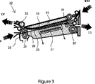
図3は、本発明の実施態様に従った熱交換ユニットの概略図である。印刷媒体は、供給ユニット3から分離され、矢印Iの方向に熱交換ユニット20の第一印刷媒体輸送経路23内に送り込まれる。この熱交換ユニット内への進入は、センサ25によって位置合わせされる。印刷媒体はピンチ21に移動され、ピンチは第一印刷媒体輸送経路23を通じて印刷媒体をピンチ22に向かって押す。ピンチ22は地域23から印刷プロセス(図示せず)に向かって矢印IIの方向に印刷媒体を引く。印刷媒体は、高圧及び高温の下で印刷媒体内に融着されるマーキング材料の画像状塗布を促進するために、印刷プロセス内部で、電気予加熱器(図示せず)によって予加熱される。印刷媒体上へのマーキング材料の塗布及びマーキング材料の融着の双方は、印刷媒体の温度を上昇する。次に、高温にある印刷媒体は、印刷プロセスから排出され、矢印IIIの方向に熱交換ユニットの第二印刷媒体輸送経路33内に送り込まれる。ピンチ31が印刷媒体を印刷プロセスからピンチ32に向かって押す。高温にある印刷媒体が第二印刷媒体輸送経路33を通じて輸送される間、第二印刷媒体が第一印刷媒体輸送経路23内に送り込まれる。第一印刷媒体輸送経路23及び第二印刷媒体輸送経路33は熱交換接触を有するので、第二印刷媒体輸送経路33内で高温にある第一印刷媒体は、第一印刷媒体輸送経路23内の第二印刷媒体にその熱エネルギを部分的に寄付し、それは熱エネルギを受け取り且つ加熱する。第一印刷媒体は第二印刷媒体に熱エネルギを寄付するので、印刷プロセスの予加熱はその熱散逸を下げ得る。高温にある印刷媒体がない場合には、例えば、システム始動時又は印刷滑動の中断後は、高温にある印刷媒体が利用可能でない限り、加熱器素子27が余分な熱エネルギの欠乏を補正し得る。
FIG. 3 is a schematic diagram of a heat exchange unit according to an embodiment of the present invention. The print medium is separated from the supply unit 3 and fed into the first print
第二印刷媒体輸送経路33内で高温にある印刷媒体と第一印刷媒体輸送経路23内の冷たい媒体との間の熱エネルギの交換を向上するために、熱交換効率が増大するよう、加圧部材35が高温にある印刷媒体上に圧力を加える。この圧力は、熱交換効率を増大するのに十分なほどに高く、印刷媒体の通過を過剰に妨げないほどに低い。加圧部材35は、約102〜200Paの圧力を印刷媒体に加えるフォーム層である。熱交換部材は固定的に開始する、即ち、部材は印刷媒体輸送経路内で印刷媒体に対して移動せず、熱交換の効率を増大する。
Pressurization to increase the heat exchange efficiency to improve the exchange of thermal energy between the print medium at a high temperature in the second print
1つの印刷媒体から他の印刷媒体へのマーキング材料の相互汚染及びスミアリングの危険性を減少するために、薄い可撓な箔28が、前記第一及び第二の印刷媒体輸送経路23,33の間に適用される。この薄い可撓な箔28は、印刷媒体が印刷媒体輸送経路23,33を通じて輸送される間にそれらが遮られないよう、極めて滑らかである。印刷媒体の静電荷電を防止するために、箔28は導電特性を有する。箔28は摩耗に対して耐性があり、低い滑り抵抗を有する。第一及び第二の印刷媒体の間の熱交換の間の箔28の熱挙動を向上するために、箔は、箔28自体の加熱が印刷媒体間の熱交換を妨げないよう、極めて薄く構成される。
In order to reduce the risk of cross-contamination and smearing of the marking material from one print medium to the other, a thin
従って、箔の熱容量及び熱抵抗性は、第一及び第二の印刷媒体の間の熱を交換するよう構成される。 Thus, the heat capacity and thermal resistance of the foil are configured to exchange heat between the first and second print media.
図4a及び4bは、本発明の実施態様に従った回転可能な案内部材を含む熱交換ユニットの概略図を示している。図4aの箱で囲まれた地域は、図4b中に拡大されて描写されている。印刷媒体輸送経路23,33の出口に、案内部材41,42が、熱交換ユニットと回転可能に接続されている。紙経路23,33を通じて輸送される印刷媒体11は、印刷媒体が引張りピンチ22及び32内に送り込まれるまで、ピンチ21及び31によってそれぞれ初期的に押される。これらの引張りピッチ22及び32は、印刷媒体輸送経路23及び33から印刷媒体を引っ張る。印刷媒体輸送経路23,33の内部の印刷媒体は、ある量の摩擦によって影響されるので、印刷媒体11からのこの引っ張りは、引っ張られるときに、印刷媒体の応力を加える。特に印刷媒体輸送経路23,33の湾曲出口地域で、この応力は生じ得る。自由に回転可能な案内部材41及び42は、これらの地域で印刷媒体11上の応力を減少し、それによって、印刷媒体及び画像完全性に影響を及ぼす危険性を減少する。
Figures 4a and 4b show schematic views of a heat exchange unit including a rotatable guide member according to an embodiment of the present invention. The area enclosed by the box in FIG. 4a is depicted enlarged in FIG. 4b.
Claims (9)
熱交換ユニットであって、
前記第一印刷媒体輸送経路に面する第一側と、前記第二印刷媒体輸送経路に面する第二の反対側とを有する固定的な熱交換部材をさらに含み、前記第二印刷媒体は、前記第一印刷媒体に対して高温にあり、前記第一印刷媒体及び前記第二印刷媒体は、前記熱交換部材を介して前記熱交換領域内で熱交換接触を有し、
前記熱交換部材は、可撓な箔である、
熱交換ユニット。A heat exchange region, a first print medium transport path configured to transport a first print medium from a supply through the heat exchange region to the print engine during operation, and a second print medium during operation to the print engine. A second print medium transport path configured for transport through the heat exchange zone from
A heat exchange unit,
And further comprising a stationary heat exchange member having a first side facing the first print medium transport path and a second opposite side facing the second print medium transport path, the second print medium comprising: The first print medium and the second print medium have a heat exchange contact in the heat exchange region via the heat exchange member ;
The heat exchange member is a flexible foil,
Heat exchange unit.
Applications Claiming Priority (3)
| Application Number | Priority Date | Filing Date | Title |
|---|---|---|---|
| EP06112926.8 | 2006-04-21 | ||
| EP06112926 | 2006-04-21 | ||
| PCT/EP2007/052003 WO2007122033A1 (en) | 2006-04-21 | 2007-03-02 | Heat exchange unit for a printing system |
Publications (2)
| Publication Number | Publication Date |
|---|---|
| JP2009534698A JP2009534698A (en) | 2009-09-24 |
| JP4885269B2 true JP4885269B2 (en) | 2012-02-29 |
Family
ID=36930379
Family Applications (2)
| Application Number | Title | Priority Date | Filing Date |
|---|---|---|---|
| JP2009505811A Expired - Fee Related JP4885269B2 (en) | 2006-04-21 | 2007-03-02 | Heat exchange unit for printing system |
| JP2009505908A Expired - Fee Related JP5291615B2 (en) | 2006-04-21 | 2007-04-20 | Heat exchange thin layer |
Family Applications After (1)
| Application Number | Title | Priority Date | Filing Date |
|---|---|---|---|
| JP2009505908A Expired - Fee Related JP5291615B2 (en) | 2006-04-21 | 2007-04-20 | Heat exchange thin layer |
Country Status (5)
| Country | Link |
|---|---|
| US (2) | US7819516B2 (en) |
| EP (2) | EP2013028B1 (en) |
| JP (2) | JP4885269B2 (en) |
| CN (2) | CN101426655B (en) |
| WO (1) | WO2007122033A1 (en) |
Families Citing this family (6)
| Publication number | Priority date | Publication date | Assignee | Title |
|---|---|---|---|---|
| EP2013028B1 (en) * | 2006-04-21 | 2012-05-16 | Océ-Technologies B.V. | Heat exchange unit for a printing system |
| JP5506331B2 (en) | 2009-10-30 | 2014-05-28 | キヤノン株式会社 | Image forming apparatus |
| US8909124B2 (en) * | 2009-10-30 | 2014-12-09 | Canon Kabushiki Kaisha | Image forming apparatus |
| JP2016517035A (en) * | 2013-03-29 | 2016-06-09 | オセ−テクノロジーズ ビーブイ | Heat exchange laminate |
| WO2014154831A1 (en) | 2013-03-29 | 2014-10-02 | Oce-Technologies B.V. | Heat exchange laminate |
| EP3099507B1 (en) | 2014-01-31 | 2019-07-31 | Hewlett-Packard Development Company, L.P. | Printing system with uniform heating |
Citations (4)
| Publication number | Priority date | Publication date | Assignee | Title |
|---|---|---|---|---|
| JPH08328412A (en) * | 1995-03-29 | 1996-12-13 | Minolta Co Ltd | Fixing method |
| JP2000122467A (en) * | 1998-10-19 | 2000-04-28 | Ricoh Co Ltd | Image forming device |
| JP2000338803A (en) * | 1999-05-27 | 2000-12-08 | Dainippon Screen Mfg Co Ltd | Electrophotographic device |
| JP2005266386A (en) * | 2004-03-19 | 2005-09-29 | Ricoh Co Ltd | Image forming apparatus |
Family Cites Families (21)
| Publication number | Priority date | Publication date | Assignee | Title |
|---|---|---|---|---|
| DE2811835A1 (en) * | 1978-03-17 | 1979-09-27 | Siemens Ag | Electrostatic copier heat fixing - uses heat exchanger to recirculate warm air from fixed copy to pre-fixing chamber |
| US5012291A (en) * | 1989-05-23 | 1991-04-30 | Delphax Systems | Powder transport, fusing and imaging apparatus |
| JPH0675489A (en) * | 1992-08-27 | 1994-03-18 | Hitachi Koki Co Ltd | Thermal fixing device and production of endless metal belt |
| US5691756A (en) | 1992-11-25 | 1997-11-25 | Tektronix, Inc. | Printer media preheater and method |
| US5564496A (en) | 1994-11-01 | 1996-10-15 | United Technologies Corporation | Composite parting sheet |
| JPH08267647A (en) * | 1995-01-11 | 1996-10-15 | Matsushita Electric Ind Co Ltd | Graphite-clad structural material and graphite part using it |
| US5752150A (en) * | 1995-09-04 | 1998-05-12 | Minolta Co., Ltd. | Heating apparatus |
| US6049680A (en) * | 1998-05-08 | 2000-04-11 | Agfa Gevaert N.V. | Apparatus for conditioning moisture content temperature of media |
| US6466454B1 (en) * | 1999-05-18 | 2002-10-15 | Ascom Energy Systems Ag | Component transformer |
| US6089703A (en) * | 1998-10-27 | 2000-07-18 | Lexmark International, Inc. | Ink jet printer and method of printing using same |
| JP2000147470A (en) * | 1998-11-06 | 2000-05-26 | Sony Corp | Liquid crystal display device |
| DE19954521C1 (en) | 1999-11-12 | 2001-06-21 | Peter Pulverich | Heat exchanger for use with acid gases comprises steel, with surfaces which come into contact with gases having coating of bitumen, ceramic or metal powder |
| JP2000197926A (en) * | 2000-01-01 | 2000-07-18 | Hitachi Metals Ltd | Fe-Ni SHEET REDUCED IN OCCURRENCE OF PUNCHING BURR, AND Fe-Ni PUNCHED PARTS |
| JP3841633B2 (en) | 2000-10-16 | 2006-11-01 | ヤマハ株式会社 | Semiconductor laser module |
| US6754457B2 (en) * | 2001-04-06 | 2004-06-22 | Nexpress Solutions Llc | Pre-heater for an electrostatographic reproduction apparatus fusing assembly |
| AU2003255075A1 (en) * | 2002-07-12 | 2004-02-02 | Xiangyang Lu | The apparatus for paperless transfer printing and the process thereof |
| JP2004170548A (en) * | 2002-11-18 | 2004-06-17 | Fuji Photo Film Co Ltd | Surface treatment device and image-forming apparatus |
| EP1508452B1 (en) * | 2003-08-19 | 2008-11-19 | Konica Minolta Business Technologies, Inc. | Ink jet printer |
| US20060225874A1 (en) | 2005-04-11 | 2006-10-12 | Shives Gary D | Sandwiched thermal article |
| WO2007122198A1 (en) * | 2006-04-21 | 2007-11-01 | Oce-Technologies B.V. | Heat exchange laminate |
| EP2013028B1 (en) * | 2006-04-21 | 2012-05-16 | Océ-Technologies B.V. | Heat exchange unit for a printing system |
-
2007
- 2007-03-02 EP EP07726597A patent/EP2013028B1/en active Active
- 2007-03-02 CN CN2007800144415A patent/CN101426655B/en not_active Expired - Fee Related
- 2007-03-02 JP JP2009505811A patent/JP4885269B2/en not_active Expired - Fee Related
- 2007-03-02 WO PCT/EP2007/052003 patent/WO2007122033A1/en active Application Filing
- 2007-04-20 CN CN200780014442XA patent/CN101426656B/en not_active Expired - Fee Related
- 2007-04-20 EP EP07728356.2A patent/EP2013029B1/en not_active Not-in-force
- 2007-04-20 JP JP2009505908A patent/JP5291615B2/en not_active Expired - Fee Related
-
2008
- 2008-10-20 US US12/254,474 patent/US7819516B2/en not_active Expired - Fee Related
- 2008-10-21 US US12/289,156 patent/US9579906B2/en active Active
Patent Citations (4)
| Publication number | Priority date | Publication date | Assignee | Title |
|---|---|---|---|---|
| JPH08328412A (en) * | 1995-03-29 | 1996-12-13 | Minolta Co Ltd | Fixing method |
| JP2000122467A (en) * | 1998-10-19 | 2000-04-28 | Ricoh Co Ltd | Image forming device |
| JP2000338803A (en) * | 1999-05-27 | 2000-12-08 | Dainippon Screen Mfg Co Ltd | Electrophotographic device |
| JP2005266386A (en) * | 2004-03-19 | 2005-09-29 | Ricoh Co Ltd | Image forming apparatus |
Also Published As
| Publication number | Publication date |
|---|---|
| JP2009534698A (en) | 2009-09-24 |
| CN101426655A (en) | 2009-05-06 |
| US9579906B2 (en) | 2017-02-28 |
| CN101426656B (en) | 2011-03-23 |
| US20090116866A1 (en) | 2009-05-07 |
| WO2007122033A1 (en) | 2007-11-01 |
| CN101426656A (en) | 2009-05-06 |
| EP2013029A1 (en) | 2009-01-14 |
| EP2013029B1 (en) | 2013-11-13 |
| CN101426655B (en) | 2012-06-20 |
| US20090047521A1 (en) | 2009-02-19 |
| JP5291615B2 (en) | 2013-09-18 |
| US7819516B2 (en) | 2010-10-26 |
| JP2009534701A (en) | 2009-09-24 |
| EP2013028A1 (en) | 2009-01-14 |
| EP2013028B1 (en) | 2012-05-16 |
Similar Documents
| Publication | Publication Date | Title |
|---|---|---|
| JP4885269B2 (en) | Heat exchange unit for printing system | |
| JP5335545B2 (en) | Image heating device | |
| CN100507752C (en) | Fixing device and image forming apparatus | |
| JP4586867B2 (en) | Fixing apparatus and image forming apparatus | |
| US10268146B2 (en) | Fixing device and image forming apparatus | |
| JP4655848B2 (en) | Fixing apparatus and image forming apparatus | |
| JP2007108464A (en) | Fixing device and image forming apparatus | |
| JP2007199383A (en) | Fixing device and image forming apparatus | |
| JP5132650B2 (en) | Heated folding system for phase change ink imaging device | |
| WO2007122198A1 (en) | Heat exchange laminate | |
| JP2001212954A (en) | Ink-jet printer | |
| JP2005221652A (en) | Fixing device and image forming apparatus | |
| US11048200B2 (en) | Guide structure and image forming apparatus | |
| JP7471563B2 (en) | Image forming device | |
| US11366413B2 (en) | Sheet-member guide structure and image forming apparatus | |
| JP2018185482A (en) | Fixing device, image forming apparatus, and program for fixing device | |
| US20210245529A1 (en) | Heating roller for ink-based image forming apparatus | |
| JP5582179B2 (en) | Bending correction device, film making device | |
| JPH10268683A (en) | Fixing device | |
| JP2000047513A (en) | Fixing device | |
| JP2005300982A (en) | Fixing apparatus | |
| JP2006069704A (en) | Image forming device | |
| JPH0962126A (en) | Fixing device | |
| JP2006215428A (en) | Recording material removing device |
Legal Events
| Date | Code | Title | Description |
|---|---|---|---|
| A621 | Written request for application examination |
Free format text: JAPANESE INTERMEDIATE CODE: A621 Effective date: 20100222 |
|
| A521 | Written amendment |
Free format text: JAPANESE INTERMEDIATE CODE: A523 Effective date: 20101215 |
|
| A131 | Notification of reasons for refusal |
Free format text: JAPANESE INTERMEDIATE CODE: A131 Effective date: 20110419 |
|
| A977 | Report on retrieval |
Free format text: JAPANESE INTERMEDIATE CODE: A971007 Effective date: 20110420 |
|
| A521 | Written amendment |
Free format text: JAPANESE INTERMEDIATE CODE: A523 Effective date: 20110701 |
|
| A131 | Notification of reasons for refusal |
Free format text: JAPANESE INTERMEDIATE CODE: A131 Effective date: 20110726 |
|
| A521 | Written amendment |
Free format text: JAPANESE INTERMEDIATE CODE: A523 Effective date: 20111025 |
|
| TRDD | Decision of grant or rejection written | ||
| A01 | Written decision to grant a patent or to grant a registration (utility model) |
Free format text: JAPANESE INTERMEDIATE CODE: A01 Effective date: 20111122 |
|
| A01 | Written decision to grant a patent or to grant a registration (utility model) |
Free format text: JAPANESE INTERMEDIATE CODE: A01 |
|
| A61 | First payment of annual fees (during grant procedure) |
Free format text: JAPANESE INTERMEDIATE CODE: A61 Effective date: 20111207 |
|
| FPAY | Renewal fee payment (event date is renewal date of database) |
Free format text: PAYMENT UNTIL: 20141216 Year of fee payment: 3 |
|
| R150 | Certificate of patent or registration of utility model |
Ref document number: 4885269 Country of ref document: JP Free format text: JAPANESE INTERMEDIATE CODE: R150 Free format text: JAPANESE INTERMEDIATE CODE: R150 |
|
| R250 | Receipt of annual fees |
Free format text: JAPANESE INTERMEDIATE CODE: R250 |
|
| R250 | Receipt of annual fees |
Free format text: JAPANESE INTERMEDIATE CODE: R250 |
|
| R250 | Receipt of annual fees |
Free format text: JAPANESE INTERMEDIATE CODE: R250 |
|
| R250 | Receipt of annual fees |
Free format text: JAPANESE INTERMEDIATE CODE: R250 |
|
| LAPS | Cancellation because of no payment of annual fees |