JP4884875B2 - motor - Google Patents

motor Download PDF

Info

Publication number
JP4884875B2
JP4884875B2 JP2006215015A JP2006215015A JP4884875B2 JP 4884875 B2 JP4884875 B2 JP 4884875B2 JP 2006215015 A JP2006215015 A JP 2006215015A JP 2006215015 A JP2006215015 A JP 2006215015A JP 4884875 B2 JP4884875 B2 JP 4884875B2
Authority
JP
Japan
Prior art keywords
stator core
pole teeth
rotor
motor
stator
Prior art date
Legal status (The legal status is an assumption and is not a legal conclusion. Google has not performed a legal analysis and makes no representation as to the accuracy of the status listed.)
Expired - Fee Related
Application number
JP2006215015A
Other languages
Japanese (ja)
Other versions
JP2008043077A (en
Inventor
信一 内海
Current Assignee (The listed assignees may be inaccurate. Google has not performed a legal analysis and makes no representation or warranty as to the accuracy of the list.)
Nidec Sankyo Corp
Original Assignee
Nidec Sankyo Corp
Priority date (The priority date is an assumption and is not a legal conclusion. Google has not performed a legal analysis and makes no representation as to the accuracy of the date listed.)
Filing date
Publication date
Application filed by Nidec Sankyo Corp filed Critical Nidec Sankyo Corp
Priority to JP2006215015A priority Critical patent/JP4884875B2/en
Priority to PCT/JP2007/000798 priority patent/WO2008018166A1/en
Priority to CN200780029185.7A priority patent/CN101501961B/en
Priority to CN2011100945820A priority patent/CN102163883B/en
Priority to US12/376,948 priority patent/US20100295392A1/en
Publication of JP2008043077A publication Critical patent/JP2008043077A/en
Application granted granted Critical
Publication of JP4884875B2 publication Critical patent/JP4884875B2/en
Expired - Fee Related legal-status Critical Current
Anticipated expiration legal-status Critical

Links

Images

Description

本発明は、モータの構成に関するものであり、より詳しくは、ステータの構造に関するものである。   The present invention relates to a configuration of a motor, and more particularly to a structure of a stator.

ステッピングモータは、一般に、永久磁石を備えたロータと、このロータの外周側に配置されたステータとを有している。また、ステータにおいて、A相のステータ組およびB相のステータ組は各々、内ステータコアと外ステータコアとを備えており、内ステータコアの第1の端板部から突出した第1の極歯と、外ステータコアの第2の端板部から突出した第2の極歯とは、周方向で交互に並んでいる。ここで、第1の極歯と第2の極歯とは、通常、同一寸法に形成されるが、第1の極歯を第2の極歯よりも短くすることもある。   A stepping motor generally includes a rotor having a permanent magnet and a stator disposed on the outer peripheral side of the rotor. Further, in the stator, each of the A-phase stator set and the B-phase stator set includes an inner stator core and an outer stator core, the first pole teeth projecting from the first end plate portion of the inner stator core, and the outer The second pole teeth protruding from the second end plate portion of the stator core are alternately arranged in the circumferential direction. Here, the first pole teeth and the second pole teeth are usually formed in the same size, but the first pole teeth may be shorter than the second pole teeth.

例えば、外ステータコアの根元部分は、ロータの永久磁石と対向しないとして、外ステータコアの端板部から突出した第2の極歯を、内ステータコアの端板部から突出した第1の極歯よりも長くした構成が提案されている(例えば、特許文献1参照)。
特開2005−269863号公報
For example, assuming that the root portion of the outer stator core does not face the permanent magnet of the rotor, the second pole teeth protruding from the end plate portion of the outer stator core are set to be more than the first pole teeth protruding from the end plate portion of the inner stator core. A lengthened configuration has been proposed (see, for example, Patent Document 1).
JP 2005-269863 A

一方のステータコアに形成された第1の極歯を他方のステータコアに形成した第2の極歯よりも短くした構成は、第1の極歯が他方のステータコアの第2の端板部に近接している場合において、第1の極歯と他方のステータコアの第2の端板部との間での漏れ磁束を抑制する対策として用いることもできる。   In the configuration in which the first pole teeth formed on one stator core are shorter than the second pole teeth formed on the other stator core, the first pole teeth are close to the second end plate portion of the other stator core. In this case, it can also be used as a measure for suppressing leakage magnetic flux between the first pole teeth and the second end plate portion of the other stator core.

しかしながら、漏れ磁束を抑制するには、第1の極歯を大幅に短くする必要があり、その結果、十分な磁界を形成できず、トルクが低下するという問題点が発生する。   However, in order to suppress the leakage magnetic flux, it is necessary to significantly shorten the first pole teeth. As a result, a sufficient magnetic field cannot be formed, and the torque is reduced.

以上の問題点に鑑みて、本発明の課題は、極歯の形状を適正化することにより、大きなトルクを得ることのできるモータを提供することにある。   In view of the above problems, an object of the present invention is to provide a motor capable of obtaining a large torque by optimizing the shape of the pole teeth.

上記課題を解決するために、本発明では、永久磁石を備えたロータと、該ロータの外周側に配置されたステータとを有し、当該ステータでは、対向配置された一対のステータコアのうち、一方のステータコアの第1の端板部から突出した第1の極歯と他方のステータコアの第2の端板部から突出した第2の極歯が周方向で交互に並んだモータにおいて、前記第1の極歯では、先端部の幅方向(周方向)の中央位置に凹部が形成されていることを特徴とする。   In order to solve the above-described problems, the present invention includes a rotor having a permanent magnet and a stator disposed on the outer peripheral side of the rotor, and the stator includes one of a pair of stator cores arranged to face each other. In the motor in which the first pole teeth protruding from the first end plate portion of the stator core and the second pole teeth protruding from the second end plate portion of the other stator core are alternately arranged in the circumferential direction, In this pole tooth, a concave portion is formed at the center position in the width direction (circumferential direction) of the tip portion.

本発明では、モータの体格を薄型化することを目的に、一方のステータコアと他方のステータコアとの対向距離を狭めた結果、一方のステータコアに形成した第1の極歯が他方のステータコアの端板部(第2の端板部)に近接している。但し、第1の極歯については、先端部の幅方向の中央位置に凹部が形成されているため、第1の極歯の先端部からの磁束漏れを防ぐことができる。それ故、第1の極歯の先端部からの磁束漏れを防いだ分だけ、隣接する極歯間に流れる磁束を増加させることができるため、大きなトルクを得ることができる。   In the present invention, as a result of reducing the facing distance between one stator core and the other stator core for the purpose of reducing the physique of the motor, the first pole teeth formed on one stator core are the end plates of the other stator core. Close to the portion (second end plate portion). However, about the 1st pole tooth, since the crevice is formed in the center position of the cross direction of a tip part, magnetic flux leakage from the tip part of the 1st pole tooth can be prevented. Therefore, since the magnetic flux flowing between the adjacent pole teeth can be increased by the amount that prevents the magnetic flux leakage from the tip portion of the first pole tooth, a large torque can be obtained.

本発明では、前記第1の極歯は、前記第2の極歯よりも短く構成されている。このように構成することにより、第1の極歯と第2の端板部との間での漏れ磁束を抑制することができる。また、一方のステータコアと他方のステータコアとの対向距離をより狭めることができるため、その分、モータの薄型化を図ることができる。   In the present invention, the first pole teeth are configured to be shorter than the second pole teeth. By comprising in this way, the leakage magnetic flux between a 1st pole tooth and a 2nd end plate part can be suppressed. Further, since the facing distance between one stator core and the other stator core can be further reduced, the motor can be made thinner accordingly.

また、本発明では、前記一方のステータコアでは、例えば、前記第1の極歯の間に切り欠きが形成されている一方、前記他方のステータコアでは、前記第2の極歯の間に第2の端板部が位置している In the present invention , the one stator core has, for example, a notch formed between the first pole teeth, while the other stator core has a second gap between the second pole teeth. The end plate is located .

さらに、本発明では、前記第2の極歯の先端部は、前記一方のステータコアの前記切り欠き内に位置し、前記第1の極歯の先端部は、前記第2の端板部に対してスラスト方向で近接して対向している Further, in the present invention, the tip end portion of the second pole tooth is located in the notch of the one stator core, and the tip end portion of the first pole tooth is located with respect to the second end plate portion. In close proximity in the thrust direction .

また、本発明では、前記ステータは、前記ロータの周りでスラスト方向に重ねて配置されたA相のステータ組とB相のステータ組とを備え、前記A相のステータ組および前記B相のステータ組は、駆動コイルのスラスト方向の両側に、前記一方のステータコアとしての内ステータコアと、前記他方のステータコアとしての外ステータコアとを備えるとともに、前記内ステータコア同士がスラスト方向で重なるように配置されている According to the present invention, the stator includes an A-phase stator set and a B-phase stator set that are arranged in a thrust direction around the rotor, and the A-phase stator set and the B-phase stator set. The set includes an inner stator core as the one stator core and an outer stator core as the other stator core on both sides in the thrust direction of the drive coil, and the inner stator cores are arranged to overlap each other in the thrust direction. .

本発明では、モータの体格を薄型化することを目的に、一方のステータコアと他方のステータコアとの対向距離を狭めた結果、一方のステータコアに形成した第1の極歯が他方のステータコアの第2の端板部に近接しているが、第1の極歯については、先端部の幅方向の中央位置に凹部が形成されているため、第1の極歯の先端部からの磁束漏れを防ぐことができる。従って、第1の極歯の先端部からの磁束漏れを防いだ分だけ、隣接する極歯間に流れる磁束を増加させることができるため、大きなトルクを得ることができる。   In the present invention, as a result of reducing the facing distance between one stator core and the other stator core for the purpose of reducing the physique of the motor, the first pole teeth formed on one stator core are the second poles of the other stator core. The first pole teeth have a recess formed at the center position in the width direction of the tip portion, so that leakage of magnetic flux from the tip portion of the first pole teeth is prevented. be able to. Therefore, since the magnetic flux flowing between the adjacent pole teeth can be increased by the amount that prevents the magnetic flux leakage from the tip portion of the first pole tooth, a large torque can be obtained.

以下に、図面を参照して、本発明を適用したモータについて説明する。   A motor to which the present invention is applied will be described below with reference to the drawings.

(モータの全体構成)
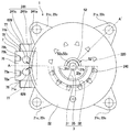
図1および図2は各々、本発明を適用したモータの平面的な構成を示す説明図、およびA−A′断面図である。なお、図1の上半部には、上ケースの上からモータを出力側からみた様子を示し、図1の下半部には、その内部に配置されたロータの平面的な構成などを示してある。図3は、本発明を適用したモータの分解斜視図である。
(General configuration of motor)
FIG. 1 and FIG. 2 are respectively an explanatory view showing a planar configuration of a motor to which the present invention is applied, and an AA ′ cross-sectional view. The upper half of FIG. 1 shows the motor viewed from the upper side of the upper case, and the lower half of FIG. 1 shows the planar configuration of the rotor disposed inside the motor. It is. FIG. 3 is an exploded perspective view of a motor to which the present invention is applied.

図1、図2および図3に示すモータ1は、平面形状が円形のステッピングモータであり、概ね、第1の外ステータコア21(他方のステータコア)、ロータ3、第1の駆動コイル61、第1の内ステータコア23(一方のステータコア)、第2の内ステータコア24(一方のステータコア)、第2の駆動コイル62、および第2の外ステータコア22(他方のステータコア)をこの順に重ねた構造を有している。第1の外ステータコア21および第2の外ステータコア22は、第1の駆動コイル61、第1の内ステータコア23、第2の内ステータコア24、および第2の駆動コイル62とともにステータ2を構成し、かつ、各々が下ケースおよび上ケースとしても用いられている。   The motor 1 shown in FIGS. 1, 2, and 3 is a stepping motor having a circular planar shape, and generally includes a first outer stator core 21 (the other stator core), the rotor 3, the first drive coil 61, and the first The inner stator core 23 (one stator core), the second inner stator core 24 (one stator core), the second drive coil 62, and the second outer stator core 22 (the other stator core) are stacked in this order. ing. The first outer stator core 21 and the second outer stator core 22 constitute the stator 2 together with the first drive coil 61, the first inner stator core 23, the second inner stator core 24, and the second drive coil 62, And each is also used as a lower case and an upper case.

(ステータの構成)
図4は、本発明を適用したモータが有する駆動コイルの説明図である。第1の外ステータコア21は、厚さが0.15mm程度の圧延鋼板を有底円筒状にプレス加工した部品であり、下底部21a(第2の端板部)の中央には、反出力側軸受51(第1の軸受)を保持するための貫通穴21bが形成されている。また、第1の外ステータコア21の下底部21aでは、貫通穴21bの周りに、複数の極歯210(第2の極歯)が等角度間隔に上方に切り起こされている。また、第1の外ステータコア21において、下底部21aから起立する胴部の開口縁には、外側に折り曲げ形成された4つの接合部21cが等角度位置で形成されている。
(Structure of stator)
FIG. 4 is an explanatory diagram of a drive coil included in a motor to which the present invention is applied. The first outer stator core 21 is a part obtained by pressing a rolled steel sheet having a thickness of about 0.15 mm into a bottomed cylindrical shape, and the lower output 21a (second end plate) has a counter-output side at the center thereof. A through hole 21b for holding the bearing 51 (first bearing) is formed. In the lower bottom portion 21a of the first outer stator core 21, a plurality of pole teeth 210 (second pole teeth) are cut upward at equal angular intervals around the through hole 21b. Further, in the first outer stator core 21, four joint portions 21c bent outward are formed at equiangular positions at the opening edge of the trunk portion that stands up from the lower bottom portion 21a.

第2の外ステータコア22も、第1の外ステータコア21と同様、厚さが0.15mm程度の圧延鋼板を有底円筒状にプレス加工した部品であり、上底部22a(第2の端板部)の中央には、出力側軸受52(第2の軸受)を保持するための貫通穴22bが形成されている。また、第2の外ステータコア22の上底部22aでも、第1の外ステータコア21と同様、貫通穴22bの周りに、複数の極歯220(第2の極歯)が等角度間隔に下方に切り起こされている。また、第2の外ステータコア22において、上底部22aから起立する胴部の開口縁では、外側に折り曲げ形成された4つの接合部22cが等角度位置で形成されており、これらの接合部22cは、第1の外ステータコア21の接合部21cと重なる位置に形成されている。   Similarly to the first outer stator core 21, the second outer stator core 22 is a part obtained by pressing a rolled steel plate having a thickness of about 0.15 mm into a bottomed cylindrical shape, and an upper bottom portion 22a (second end plate portion). ) Is formed with a through hole 22b for holding the output side bearing 52 (second bearing). Also, in the upper bottom portion 22a of the second outer stator core 22, like the first outer stator core 21, a plurality of pole teeth 220 (second pole teeth) are cut downward at equal angular intervals around the through hole 22b. It has been awakened. Further, in the second outer stator core 22, at the opening edge of the body portion that stands up from the upper bottom portion 22a, four joint portions 22c that are bent outward are formed at equiangular positions, and these joint portions 22c are The first outer stator core 21 is formed at a position overlapping the joint 21c.

第1の内ステータコア23は、厚さが0.15mm程度の圧延鋼板を環状にプレス加工した部品であり、環状フランジ部23a(第1の端板部)の内周縁の等角度間隔の位置で下方に屈曲する複数の極歯230(第1の極歯)と、複数の極歯230の各間に形成された切り欠き235と、外周縁から平行に突出する2つの突出部231(第1の突出部)とを備えている。これらの突出部231は各々、第1の内ステータコア23の環状部分から水平に延びた基部231aと、途中で下方に屈曲する屈曲部231bと、屈曲部231bから水平に延びた水平板部231cとを備えており、後述する給電用基板7を保持するための基板保持部として機能する。   The first inner stator core 23 is a part obtained by annularly pressing a rolled steel plate having a thickness of about 0.15 mm, and is positioned at equiangular intervals on the inner peripheral edge of the annular flange portion 23a (first end plate portion). A plurality of pole teeth 230 (first pole teeth) bent downward, a notch 235 formed between each of the plurality of pole teeth 230, and two projecting portions 231 (first first) projecting in parallel from the outer peripheral edge Projecting part). Each of these protrusions 231 includes a base portion 231a extending horizontally from the annular portion of the first inner stator core 23, a bent portion 231b bent downward halfway, and a horizontal plate portion 231c extending horizontally from the bent portion 231b. And functions as a substrate holder for holding a power supply substrate 7 described later.

第2の内ステータコア24も、第1の内ステータコア23と同様、厚さが0.15mm程度の圧延鋼板を環状にプレス加工した部品であり、環状フランジ部24a(第1の端板部)内周縁の等角度間隔の位置で上方に屈曲する複数の極歯240(第1の極歯)と、複数の極歯240の各間に形成された切り欠き245と、外周縁から平行に突出する2つの突出部241(第2の突出部)を備えている。これらの突出部241は各々、第2の内ステータコア24の環状部分から水平に延びた基部241aと、途中で上方に屈曲する屈曲部241bと、屈曲部241bから水平に延びた水平板部241cとを備えており、後述する給電用基板7を保持するための基板保持部として機能する。   Similarly to the first inner stator core 23, the second inner stator core 24 is a part obtained by annularly pressing a rolled steel plate having a thickness of about 0.15 mm, and is provided in the annular flange portion 24a (first end plate portion). A plurality of pole teeth 240 (first pole teeth) bent upward at equal angular intervals on the periphery, a notch 245 formed between each of the plurality of pole teeth 240, and projecting in parallel from the outer periphery Two protrusions 241 (second protrusions) are provided. Each of the projecting portions 241 includes a base portion 241a extending horizontally from the annular portion of the second inner stator core 24, a bent portion 241b bent upward in the middle, and a horizontal plate portion 241c extending horizontally from the bent portion 241b. And functions as a substrate holder for holding a power supply substrate 7 described later.

なお、第1の内ステータコア23および第2の内ステータコア24では、複数の極歯230、240の各間に切り欠き235、245が形成されているが、第1の外ステータコア21および第2の外ステータコア22では、複数の極歯210、220の各間に切り欠きが形成されておらず、複数の極歯210、220を切り起こしによる穴のみが形成されている。   In the first inner stator core 23 and the second inner stator core 24, notches 235 and 245 are formed between the plurality of pole teeth 230 and 240, but the first outer stator core 21 and the second inner stator core 24 In the outer stator core 22, notches are not formed between each of the plurality of pole teeth 210 and 220, but only a hole formed by cutting and raising the plurality of pole teeth 210 and 220 is formed.

第1の駆動コイル61および第2の駆動コイル62は、図4(A)に示すように、平角線からなるコイル線をアルファ巻きにて所定回数、巻き回すことにより形成された扁平な空芯コイルであり、コイル線は、軸線方向に2段、径方向に多層に巻回されている。このようなアルファ巻きの空芯コイルは、円筒形あるいは円柱状の冶具の外周面に対してコイル線の途中部分を巻回した後、一方の端部を冶具に多層に巻回する一方、他方の端部を隣接する箇所で多層に巻回することにより得られ、コイル線を被覆する熱融着層により、形状が保持されている。   As shown in FIG. 4A, the first drive coil 61 and the second drive coil 62 are flat air cores formed by winding a coil wire made of a flat wire a predetermined number of times by alpha winding. The coil is wound in two stages in the axial direction and in multiple layers in the radial direction. Such an alpha-winding air-core coil is formed by winding an intermediate portion of a coil wire around the outer peripheral surface of a cylindrical or columnar jig, and then winding one end in a multilayer on the jig, The shape is maintained by a heat-sealing layer that covers the coil wire, and is obtained by winding the end portions of the wire in multiple layers at adjacent locations.

このような第1の駆動コイル61では、2本の巻線端末618、619はいずれも巻き終わり端末に相当し、第1の駆動コイル61の端面に重なることなく、外側に引き出されている。また、第2の駆動コイル62でも、2本の巻線端末628、629はいずれも巻き終わり端末に相当し、第2の駆動コイル62の端面に重なることなく、外側に引き出されている。それ故、第1の駆動コイル61および第2の駆動コイル62は、内周から端面を通って外周に引き出される巻始め端末がない分、薄く形成されている。   In such a first drive coil 61, the two winding terminals 618 and 619 are both equivalent to winding end terminals, and are drawn to the outside without overlapping the end face of the first drive coil 61. Also, in the second drive coil 62, the two winding terminals 628 and 629 are both equivalent to winding end terminals, and are drawn to the outside without overlapping the end face of the second drive coil 62. Therefore, the first drive coil 61 and the second drive coil 62 are formed thin as there is no winding start terminal drawn from the inner periphery to the outer periphery through the end face.

巻線端末618、619は、第1の駆動コイル61の外周部分において互いに近接した位置まで巻回され、かかる近接位置で折り曲げられて半径方向外側に平行に引き出されている。また、巻線端末628、629も、第2の駆動コイル62の外周部分において互いに近接した位置まで巻回され、かかる近接位置で折り曲げられて半径方向外側に平行に引き出されている。   The winding terminals 618 and 619 are wound to positions close to each other on the outer peripheral portion of the first drive coil 61, bent at such close positions, and drawn out in parallel to the radial outside. The winding terminals 628 and 629 are also wound to positions close to each other on the outer peripheral portion of the second drive coil 62, bent at the close positions, and drawn out in parallel to the radial outside.

このように構成した第1の外ステータコア21、第1の駆動コイル61、第1の内ステータコア23、第2の内ステータコア24、第2の駆動コイル62、および第2の外ステータコア22をスラスト方向に重ねてステータ2を構成する際には、第1の駆動コイル61の両面に絶縁シート65を重ねる一方、第2の駆動コイル62の両面に絶縁シート65を重ねる。   The first outer stator core 21, the first drive coil 61, the first inner stator core 23, the second inner stator core 24, the second drive coil 62, and the second outer stator core 22 thus configured are thrust. When the stator 2 is configured to overlap, the insulating sheet 65 is stacked on both surfaces of the first drive coil 61, while the insulating sheet 65 is stacked on both surfaces of the second drive coil 62.

(給電用基板7の構成)
本形態のモータ1では、第1の駆動コイル61および第2の駆動コイル62に対する給電は、ガラス−エポキシ基板やフェノール基板からなる共通の給電用基板7によって行われる。このため、給電用基板7の上面(出力側端面)には、第2の駆動コイル62の巻線端末628、629が半田接続されるランド部71a、71bと、後述するフレキシブル配線基板9との接続が行われるランド部73a、73bと、対応するランド部同士を接続する配線部72a、72bとが形成されている。
(Configuration of power supply substrate 7)
In the motor 1 of this embodiment, power is supplied to the first drive coil 61 and the second drive coil 62 by a common power supply substrate 7 made of a glass-epoxy substrate or a phenol substrate. For this reason, land portions 71a and 71b to which the winding terminals 628 and 629 of the second drive coil 62 are solder-connected to the upper surface (output side end surface) of the power supply substrate 7 and the flexible wiring substrate 9 to be described later. Land portions 73a and 73b to be connected and wiring portions 72a and 72b for connecting the corresponding land portions are formed.

ここで、巻線端末628、629は、第2の駆動コイル62の外周面において互いに近接した位置で平行に引き出されているため、給電用基板7において、巻線端末628、629が半田接続されるランド部71a、71b同士は、互いに近接した位置に配置され、フレキシブル配線基板9との接続が行われるランド部73a、73b同士、および配線部72a、72b同士も近接した位置に並列配置されている。   Here, since the winding terminals 628 and 629 are drawn out in parallel at positions close to each other on the outer peripheral surface of the second drive coil 62, the winding terminals 628 and 629 are soldered on the power supply substrate 7. The land portions 71a and 71b are arranged in close proximity to each other, and the land portions 73a and 73b to be connected to the flexible wiring board 9 and the wiring portions 72a and 72b are also arranged in parallel in close proximity to each other. Yes.

給電用基板7は両面基板であり、図示を省略するが、給電用基板7の下面(反出力側端面)は、給電用基板7の上面と同様に構成され、給電用基板7の下面には、第1の駆動コイル61の巻線端末618、619が半田接続されるランド部と、フレキシブル配線基板との接続が行われるランド部と、対応するランド部同士を接続する配線部とが形成されている。   Although the power supply substrate 7 is a double-sided substrate and is not shown, the lower surface (the non-output side end surface) of the power supply substrate 7 is configured in the same manner as the upper surface of the power supply substrate 7. The land portions to which the winding terminals 618 and 619 of the first drive coil 61 are solder-connected, the land portions to be connected to the flexible wiring board, and the wiring portions to connect the corresponding land portions are formed. ing.

ここで、巻線端末628、629は、給電用基板7の上面に沿うように引き出されている一方、巻線端末618、619は、給電用基板7の下面に沿うように引き出されている。このため、端子が一体に形成された樹脂ボビンによって端子台などを形成しなくても、1枚の両面基板(給電用基板7)を用いるだけで、第1の駆動コイル61および第2の駆動コイル62に対する端末処理を容易に行うことができる。   Here, the winding terminals 628 and 629 are drawn out along the upper surface of the power supply substrate 7, while the winding terminals 618 and 619 are drawn out along the lower surface of the power supply substrate 7. For this reason, the first drive coil 61 and the second drive can be obtained by using only one double-sided board (feeding board 7) without forming a terminal block or the like by a resin bobbin in which terminals are integrally formed. Terminal processing for the coil 62 can be easily performed.

本形態において、給電用基板7は、ランド部71a、71b、配線部72a、72b、およびランド部73a、73bなどが形成された矩形の本体部分76と、本体部分76の側端部から両側に突出する矩形の連結部77とを備えている。連結部77は、本体部分76に比して小さく、本体部分76と連結部77との間には段部78が形成されている。   In this embodiment, the power supply substrate 7 includes a rectangular main body portion 76 in which land portions 71a and 71b, wiring portions 72a and 72b, land portions 73a and 73b, and the like are formed on both sides from the side end portion of the main body portion 76. And a protruding rectangular connecting portion 77. The connecting portion 77 is smaller than the main body portion 76, and a stepped portion 78 is formed between the main body portion 76 and the connecting portion 77.

(ロータの構成)
ロータ3は、丸棒状の回転軸35と、カップ形のロータケース31と、周方向にS極とN極とが交互に着磁されたリング状の永久磁石32とから構成されている。ロータケース31は、回転軸35が嵌る内周側円筒部31bと、外周面に永久磁石32が固着された外周側円筒部31cと、外周側円筒部31cと内周側円筒部31bとを連結する環状平板部31aとを備えている。本形態において、ロータケース31は、平板状の部材に対して絞り加工(プレス加工)を施すことにより形成され、内周側円筒部31bおよび外周側円筒部31cは各々、環状平板部31aの内周縁および外周縁から出力側に向けて起立した構造になっている。永久磁石32のスラスト方向の寸法(幅寸法)は、外周側円筒部31cのスラスト方向の寸法(幅寸法)よりも広く、永久磁石32のスラスト方向の両端部は、外周側円筒部31cの上端部および下端部からスラスト方向にはみ出た状態にある。このため、永久磁石32とステータ2との対向面積が広い。
(Configuration of rotor)
The rotor 3 includes a round bar-shaped rotating shaft 35, a cup-shaped rotor case 31, and a ring-shaped permanent magnet 32 in which S and N poles are alternately magnetized in the circumferential direction. The rotor case 31 connects an inner peripheral cylindrical portion 31b into which the rotation shaft 35 is fitted, an outer peripheral cylindrical portion 31c having a permanent magnet 32 fixed to the outer peripheral surface, and the outer peripheral cylindrical portion 31c and the inner peripheral cylindrical portion 31b. And an annular flat plate portion 31a. In this embodiment, the rotor case 31 is formed by subjecting a flat plate member to drawing (pressing), and the inner peripheral cylindrical portion 31b and the outer peripheral cylindrical portion 31c are respectively included in the annular flat plate portion 31a. The structure stands up from the peripheral edge and the outer peripheral edge toward the output side. The dimension (width dimension) in the thrust direction of the permanent magnet 32 is wider than the dimension (width dimension) in the thrust direction of the outer peripheral cylindrical part 31c, and both end parts of the permanent magnet 32 in the thrust direction are the upper ends of the outer cylindrical part 31c. It is in the state which protruded in the thrust direction from the part and the lower end part. For this reason, the opposing area of the permanent magnet 32 and the stator 2 is large.

(軸受の構成)
本形態において、第1の外ステータコア21に保持された反出力側軸受51は樹脂製であり、大径の円盤部51aと、円盤部51aから反出力側に向けて突出する円筒部51bとを備えている。反出力側軸受51の中央には、貫通穴からなる軸穴51eが形成されており、かかる軸穴51eには、回転軸35の反出力側端部が挿入される。このような構成の反出力側軸受51は、円盤部51aと円筒部51bとの段部51fで第1の外ステータコア21に位置決めされるまで、円筒部51bが第1の外ステータコア21の貫通穴21bに圧入され、第1の外ステータコア21に固定されている。
(Bearing configuration)
In this embodiment, the non-output side bearing 51 held by the first outer stator core 21 is made of resin, and includes a large-diameter disk part 51a and a cylindrical part 51b protruding from the disk part 51a toward the non-output side. I have. A shaft hole 51e made of a through hole is formed in the center of the counter-output side bearing 51, and the counter-output side end of the rotary shaft 35 is inserted into the shaft hole 51e. The counter-output side bearing 51 having such a configuration is such that the cylindrical portion 51b is positioned in the through hole of the first outer stator core 21 until the step 51f of the disk portion 51a and the cylindrical portion 51b positions the first outer stator core 21. It is press-fitted into 21 b and is fixed to the first outer stator core 21.

第2の外ステータコア22に保持された出力側軸受52は、金属焼結体に潤滑油を含有させてなる焼結含油軸受からなり、反出力側から出力側に向かって、大径部52c、中径部52bおよび小径部52aがこの順に形成されている。出力側軸受52には、大径部52cおよび中径部52bにかけては、反出力側端面で開口する凹部52dが形成されており、この凹部52dの底部52gでは、小径部52aを貫通する軸穴52eが形成されている。かかる軸穴52eには、回転軸35の出力側端部が挿入される。このような構成の出力側軸受52は、中径部52bが第2の外ステータコア22の貫通穴22bに嵌められた状態で、中径部52bと大径部52cとの段部52fで位置決めされた状態で、加締などの方法で第2の外ステータコア22に固定されている。   The output-side bearing 52 held by the second outer stator core 22 is a sintered oil-impregnated bearing in which a lubricant is contained in a metal sintered body, and has a large diameter portion 52c from the counter-output side toward the output side. The medium diameter part 52b and the small diameter part 52a are formed in this order. The output-side bearing 52 is formed with a recess 52d that opens at the opposite end face on the large-diameter portion 52c and the medium-diameter portion 52b. A shaft hole that penetrates the small-diameter portion 52a is formed at the bottom 52g of the recess 52d. 52e is formed. The output side end of the rotating shaft 35 is inserted into the shaft hole 52e. The output side bearing 52 having such a configuration is positioned by a stepped portion 52f of the medium diameter portion 52b and the large diameter portion 52c in a state where the medium diameter portion 52b is fitted in the through hole 22b of the second outer stator core 22. In this state, it is fixed to the second outer stator core 22 by a method such as caulking.

(モータの製造方法およびステータの詳細説明)
図1〜図4に加えて、図5および図6も参照して、本発明を適用したモータの製造方法を説明しながら、本発明を適用したモータの構造をさらに説明する。
(Detailed explanation of motor manufacturing method and stator)
The structure of the motor to which the present invention is applied will be further described with reference to FIGS. 5 and 6 in addition to FIGS. 1 to 4 while describing the method for manufacturing the motor to which the present invention is applied.

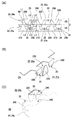
図5(A)〜(D)は各々、本発明を適用したモータのステータなどの構成を示す説明図である。図6(A)〜(C)は、本発明を適用したモータが有する極歯を拡大して示す側面図、A相のステータの極歯の構成を模式的に示す斜視図、およびB相のステータの極歯の構成を模式的に示す斜視図である。   FIGS. 5A to 5D are explanatory views showing the configuration of the stator of the motor to which the present invention is applied. 6A to 6C are side views showing enlarged pole teeth of a motor to which the present invention is applied, a perspective view schematically showing a configuration of pole teeth of a phase A stator, and phase B It is a perspective view which shows typically the structure of the pole tooth of a stator.

本形態のモータ1を製造するには、まず、図1〜図3を参照して説明したロータケース31の内周側円筒部31bに回転軸35を圧入などの方法で固定する一方、外周側円筒部31cの外周面に永久磁石32を接着などの方法で固定し、ロータ3を組み立てておく。また、第1の外ステータコア21の貫通穴21bに反出力側軸受51を圧入などの方法で固定する一方、第2の外ステータコア22の貫通穴22bに出力側軸受52を加締などの方法で固定しておく。   In order to manufacture the motor 1 of this embodiment, first, the rotating shaft 35 is fixed to the inner peripheral side cylindrical portion 31b of the rotor case 31 described with reference to FIGS. The permanent magnet 32 is fixed to the outer peripheral surface of the cylindrical portion 31c by a method such as adhesion, and the rotor 3 is assembled. Further, the output-side bearing 51 is fixed to the through hole 21b of the first outer stator core 21 by a method such as press fitting, while the output side bearing 52 is fixed to the through hole 22b of the second outer stator core 22 by a method such as caulking. Keep it fixed.

次に、第1の内ステータコア23と第2の内ステータコア24とを、図5(A)に示すように、極歯230、240が互いに反対側を向くように重ね合わせて接合する。その際、第1の内ステータコア23の2つの突出部231と、第2の内ステータコア24の2つの突出部241が互いに重なるので、突出部231、241の間に給電用基板7の両端部に形成されている連結部77を挟持する。すなわち、突出部231、241では、屈曲部231b、241bによって、先端側の水平板部231c、241cが互いに離間する位置で延びて、水平板部231c、241cの間には給電用基板7の厚さに相当する隙間が形成されており、かかる隙間内に給電用基板7の連結部77を保持することができる。その結果、給電用基板7は、第1の内ステータコア23および第2の内ステータコア24の外周側でモータ軸線に対して略垂直姿勢で保持される。   Next, as shown in FIG. 5A, the first inner stator core 23 and the second inner stator core 24 are overlapped and joined such that the pole teeth 230 and 240 face each other. At this time, since the two protrusions 231 of the first inner stator core 23 and the two protrusions 241 of the second inner stator core 24 overlap each other, the both ends of the power supply substrate 7 are disposed between the protrusions 231 and 241. The formed connecting part 77 is sandwiched. That is, in the protrusions 231 and 241, the horizontal plate portions 231 c and 241 c on the front end side are extended by the bent portions 231 b and 241 b, and the thickness of the power supply substrate 7 is between the horizontal plate portions 231 c and 241 c. A gap corresponding to this is formed, and the connecting portion 77 of the power feeding substrate 7 can be held in the gap. As a result, the power supply substrate 7 is held in a substantially vertical posture with respect to the motor axis on the outer peripheral side of the first inner stator core 23 and the second inner stator core 24.

次に、図5(B)に示すように、第1の内ステータコア23の下面に絶縁シート65を介して第1の駆動コイル61を重ねるとともに、第2の内ステータコア24の上面に絶縁シート65を介して第2の駆動コイル62を重ねる。その結果、第2の駆動コイル62の巻線端末628、629は、給電用基板7の上面に形成されたランド部71a、71bに重なるので、巻線端末628、629を各々、給電用基板7のランド部71a、71bに半田により接続する。同様に、第1の駆動コイル61の巻線端末618、619も、給電用基板7の下面に形成されたランド部(図示せず)に重なるので、巻線端末618、619を各々、給電用基板7のランド部に半田により接続する。   Next, as shown in FIG. 5B, the first drive coil 61 is overlaid on the lower surface of the first inner stator core 23 via the insulating sheet 65, and the insulating sheet 65 is disposed on the upper surface of the second inner stator core 24. The second drive coil 62 is stacked via As a result, the winding terminals 628 and 629 of the second drive coil 62 overlap with the land portions 71a and 71b formed on the upper surface of the power feeding substrate 7, so that the winding terminals 628 and 629 are respectively connected to the power feeding substrate 7. The land portions 71a and 71b are connected by solder. Similarly, since the winding terminals 618 and 619 of the first drive coil 61 also overlap with land portions (not shown) formed on the lower surface of the power supply substrate 7, the winding terminals 618 and 619 are respectively used for power supply. The land portion of the substrate 7 is connected by solder.

ここで、第2の駆動コイル62の巻線端末628、629のうち、図4(B)に示すように、上層から引き出された巻線端末628を捻って引き出し位置よりやや下方で延ばしておけば、第2の内ステータコア24の上面に第2の駆動コイル62を重ねるだけで、巻線端末628、629の先端部分が給電用基板7の上面に接した状態で重なる。それ故、巻線端末628、629を各々、給電用基板7のランド部71a、71bに容易に半田により接続することができる。なお、巻線端末628、629の双方を捻ることにより、巻線端末628、629の先端部分を給電用基板7の上面に接した状態で重ねてもよい。また、巻線端末628、629の双方を捻って給電用基板7に対して水平な状態したのち、巻線端末628、629を各々、給電用基板7のランド部71a、71bに半田により接続してもよい。なお、第1の駆動コイル61の巻線端末618、619についても同様である。   Here, of the winding terminals 628 and 629 of the second drive coil 62, as shown in FIG. 4B, the winding terminal 628 drawn from the upper layer is twisted and extended slightly below the drawing position. For example, only the second drive coil 62 is placed on the upper surface of the second inner stator core 24, and the leading ends of the winding terminals 628 and 629 overlap with the upper surface of the power supply substrate 7. Therefore, the winding terminals 628 and 629 can be easily connected to the land portions 71a and 71b of the power supply substrate 7 by soldering. Note that, by twisting both of the winding terminals 628 and 629, the end portions of the winding terminals 628 and 629 may be overlapped with each other in contact with the upper surface of the power supply substrate 7. Further, after twisting both of the winding terminals 628 and 629 to be in a horizontal state with respect to the power supply board 7, the winding terminals 628 and 629 are respectively connected to the land portions 71a and 71b of the power supply board 7 by soldering. May be. The same applies to the winding terminals 618 and 619 of the first drive coil 61.

次に、第1の駆動コイル61、第1の内ステータコア23、第2の内ステータコア24および第2の駆動コイル62の積層体の内側にロータ3を通した後、図5(C)に示すように、第1の駆動コイル61の下面に絶縁シート65を介して第1の外ステータコア21を重ねるとともに、第2の駆動コイル62の上面に絶縁シート65を介して第2の外ステータコア22を重ねる。その際、第1の外ステータコア21に保持された反出力側軸受51の軸穴51eに回転軸35の反出力側軸端を挿入する一方、第2の外ステータコア22に保持された出力側軸受52の軸穴52eに回転軸35の出力側軸端を挿入する。しかる後に、第1の外ステータコア21および第2の外ステータコア22の接合部21c、22c同士を溶接、加締などの方法で接合する。   Next, after passing the rotor 3 inside the laminated body of the first drive coil 61, the first inner stator core 23, the second inner stator core 24, and the second drive coil 62, it is shown in FIG. As described above, the first outer stator core 21 is overlaid on the lower surface of the first drive coil 61 via the insulating sheet 65, and the second outer stator core 22 is disposed on the upper surface of the second drive coil 62 via the insulating sheet 65. Overlapping. At that time, the output-side bearing held by the second outer stator core 22 is inserted into the shaft hole 51e of the counter-output-side bearing 51 held by the first outer stator core 21 while the opposite-output-side shaft end of the rotary shaft 35 is inserted. The output side shaft end of the rotating shaft 35 is inserted into the shaft hole 52e of 52. Thereafter, the joint portions 21c and 22c of the first outer stator core 21 and the second outer stator core 22 are joined by a method such as welding or caulking.

このようにしてステータ2を組み立てると、ステータ2の内側にロータ3が回転可能な状態で保持される。また、ロータケース31の内周側円筒部31bは、出力側軸受52の凹部52dに入り込むので、薄いステータ2の内側にロータ3を配置することができる。ここで、ロータケース31の外径寸法は、反出力側軸受51の外径寸法、および出力側軸受52の外径寸法よりも大きいので、永久磁石32は、反出力側軸受51および出力側軸受52のいずれよりも半径方向外側に配置される。   When the stator 2 is assembled in this way, the rotor 3 is held inside the stator 2 in a rotatable state. Further, since the inner circumferential side cylindrical portion 31 b of the rotor case 31 enters the recess 52 d of the output side bearing 52, the rotor 3 can be disposed inside the thin stator 2. Here, since the outer diameter dimension of the rotor case 31 is larger than the outer diameter dimension of the non-output side bearing 51 and the outer diameter dimension of the output side bearing 52, the permanent magnet 32 is composed of the anti-output side bearing 51 and the output side bearing. It is arranged radially outward from any of 52.

このように構成したステータ2では、図6(A)、(B)に示すように、第1の外ステータコア21、第1の駆動コイル61、および第1の内ステータコア23によって、A相のステータ組2Aが構成され、このステータ組2Aでは、ステータ2の内周面に沿って、第1の外ステータコア21の極歯210と、第1の内ステータコア23の極歯230とが交互に並ぶ。   In the stator 2 configured as described above, as shown in FIGS. 6A and 6B, the first outer stator core 21, the first drive coil 61, and the first inner stator core 23 constitute an A-phase stator. A set 2A is configured, and in the stator set 2A, the pole teeth 210 of the first outer stator core 21 and the pole teeth 230 of the first inner stator core 23 are alternately arranged along the inner peripheral surface of the stator 2.

ここで、第1の内ステータコア23には、複数の極歯230の各間に切り欠き235が形成されており、第1の外ステータコア21の極歯210が延びている先端側には切り欠き235が位置する。従って、極歯210は、長さ寸法L1という長い寸法をもって延びているが、極歯210の先端部は、切り欠き235の内側に位置するので、第1の内ステータコア23との間に十分な隙間が確保されている。このため、極歯210と第1の内ステータコア23との間の漏れ磁束が問題とならない。   Here, the first inner stator core 23 has a notch 235 formed between each of the plurality of pole teeth 230, and the notch is formed on the tip end side where the pole teeth 210 of the first outer stator core 21 extend. 235 is located. Therefore, although the pole tooth 210 extends with a long dimension of the length dimension L 1, the tip portion of the pole tooth 210 is located inside the notch 235, so that it is sufficient between the first inner stator core 23. A gap is secured. For this reason, the leakage magnetic flux between the pole teeth 210 and the first inner stator core 23 does not matter.

これに対して、第1の外ステータコア21では、複数の極歯210の各間に切り欠きが形成されていないので、第1の内ステータコア23の極歯230が延びている先端側には、第1の外ステータコア21の下底部21aが位置する。ここで、極歯230の先端部と第1の外ステータコア21の下底部21aとの距離が狭いと、極歯230の先端部から下底部21aに向かって磁束が漏れてしまい、その分、極歯210、230間で飛ぶトルクに有効な磁束が少なくなってしまう。そこで、本形態では、極歯230については、幅方向の両側部分を十分な長さ寸法L2(L1>L2)にする一方、漏れ磁束が発生しやすい幅方向の中央部分に凹部25を形成し、幅方向の中央部分を長さ寸法L3(L1>L2>L3)まで短くすることにより、第1の外ステータコア21との間の漏れ磁束が問題とならないようにしてある。   On the other hand, in the first outer stator core 21, no notch is formed between each of the plurality of pole teeth 210. Therefore, on the tip side where the pole teeth 230 of the first inner stator core 23 extend, The lower bottom portion 21a of the first outer stator core 21 is located. Here, if the distance between the tip portion of the pole tooth 230 and the lower bottom portion 21a of the first outer stator core 21 is narrow, the magnetic flux leaks from the tip portion of the pole tooth 230 toward the lower bottom portion 21a. The magnetic flux effective for the torque flying between the teeth 210 and 230 is reduced. Therefore, in the present embodiment, for the pole teeth 230, both side portions in the width direction are set to a sufficient length L2 (L1> L2), while the recess 25 is formed in the center portion in the width direction where leakage flux is likely to occur. By shortening the central portion in the width direction to the length L3 (L1> L2> L3), the leakage magnetic flux between the first outer stator core 21 and the first outer stator core 21 does not become a problem.

また、ステータ2では、図6(A)、(C)に示すように、第2の外ステータコア22、第2の駆動コイル62、および第2の内ステータコア24によって、B相のステータ組2Bが構成され、このステータ組2Bでは、ステータ2の内周面に沿って、第2の外ステータコア22の極歯220と、第2の内ステータコア24の極歯240とが交互に並ぶ。   In the stator 2, as shown in FIGS. 6A and 6C, the second outer stator core 22, the second drive coil 62, and the second inner stator core 24 form a B-phase stator set 2 </ b> B. In this stator set 2 </ b> B, the pole teeth 220 of the second outer stator core 22 and the pole teeth 240 of the second inner stator core 24 are alternately arranged along the inner peripheral surface of the stator 2.

ここで、第2の内ステータコア24には、複数の極歯240の各間に切り欠き245が形成されており、第2の外ステータコア22の極歯220が延びている先端側には切り欠き245が位置する。従って、極歯240は、長さ寸法L1という長い寸法をもって延びているが、極歯240の先端部は、切り欠き245の内側に位置するので、第2の内ステータコア24との間に十分な隙間が確保されている。このため、極歯220と第2の内ステータコア24との間の漏れ磁束が問題とならない。   Here, the second inner stator core 24 has a notch 245 formed between each of the plurality of pole teeth 240, and a notch is formed on the tip end side where the pole teeth 220 of the second outer stator core 22 extend. 245 is located. Accordingly, the pole teeth 240 extend with a long dimension of the length dimension L 1, but the tip portion of the pole teeth 240 is located inside the notch 245, so that there is sufficient space between the pole teeth 240 and the second inner stator core 24. A gap is secured. For this reason, the leakage magnetic flux between the pole teeth 220 and the second inner stator core 24 does not matter.

これに対して、第2の外ステータコア22では、複数の極歯220の各間に切り欠きが形成されていないので、第2の内ステータコア24の極歯240が延びている先端側には、第2の外ステータコア22の上底部22aが位置する。ここで、極歯240の先端部と第2の外ステータコア22の上底部22aとの距離が狭いと、極歯240の先端部から上底部22aに向かって磁束が漏れてしまい、その分、極歯220、240間で飛ぶトルクに有効な磁束が少なくなってしまう。そこで、本形態では、極歯240については、幅方向の両側部分を十分な長さ寸法L2(L1>L2)にする一方、漏れ磁束が発生しやすい幅方向の中央部分に凹部25を形成し、幅方向の中央部分を長さ寸法L3(L1>L2>L3)まで短くすることにより、第2の外ステータコア22との間の漏れ磁束が問題とならないようにしてある。   On the other hand, in the second outer stator core 22, since notches are not formed between the plurality of pole teeth 220, the tip end side of the second inner stator core 24 where the pole teeth 240 extend is The upper bottom portion 22a of the second outer stator core 22 is located. Here, if the distance between the tip portion of the pole tooth 240 and the upper bottom portion 22a of the second outer stator core 22 is narrow, the magnetic flux leaks from the tip portion of the pole tooth 240 toward the upper bottom portion 22a. The magnetic flux effective for the torque flying between the teeth 220 and 240 is reduced. Therefore, in the present embodiment, for the pole teeth 240, both side portions in the width direction are set to a sufficient length L2 (L1> L2), while the recess 25 is formed in the center portion in the width direction where leakage flux is likely to occur. By shortening the central portion in the width direction to the length dimension L3 (L1> L2> L3), the leakage magnetic flux between the second outer stator core 22 does not become a problem.

このようにしてモータ1の主要部分を構成した後、外部との接続に用いるフレキシブル配線基板9のスリット91に給電用基板7の端部を通し、フレキシブル配線基板9を給電用基板7に対して略垂直姿勢で配置する。ここで、給電用基板7には、本体部分76の両側に小さな連結部77が形成されており、給電用基板7の外周側に位置する端部では、連結部77の外周側に位置する端部が本体部分76の端部からみて引っ込んだ位置にある。また、フレキシブル配線基板9のスリット91の長さ寸法は、給電用基板7の本体部分76の長さ寸法よりわずかに長い。このため、フレキシブル配線基板9のスリット91に給電用基板7の端部を通した際、フレキシブル配線基板9においてスリット91の長さ方向で挟む両側部分の裏面が連結部77の端部に当接し、位置決めされる。なお、フレキシブル配線基板9の裏面を突出部231、241の先端部に当接させて、フレキシブル配線基板9の位置決めを行ってもよい。   After constituting the main part of the motor 1 in this way, the end of the power supply substrate 7 is passed through the slit 91 of the flexible wiring substrate 9 used for connection to the outside, and the flexible wiring substrate 9 is connected to the power supply substrate 7. Arrange in a substantially vertical position. Here, the power supply substrate 7 is formed with small connecting portions 77 on both sides of the main body portion 76, and the end located on the outer peripheral side of the power supply substrate 7 is the end located on the outer peripheral side of the connecting portion 77. The portion is in a retracted position when viewed from the end of the main body portion 76. Further, the length dimension of the slit 91 of the flexible wiring board 9 is slightly longer than the length dimension of the main body portion 76 of the power supply board 7. For this reason, when the end portion of the power supply substrate 7 is passed through the slit 91 of the flexible wiring substrate 9, the back surfaces of both side portions sandwiched in the length direction of the slit 91 in the flexible wiring substrate 9 abut on the end portion of the connecting portion 77. Is positioned. The flexible wiring board 9 may be positioned by bringing the back surface of the flexible wiring board 9 into contact with the tip portions of the protrusions 231 and 241.

ここで、フレキシブル配線基板9には、スリット91を挟む両側位置に計4つのランド部92a、92b、92c、92dが形成されているとともに、これらのランド部92a、92b、92c、92dから延びた配線パターン(図示せず)が形成されている。また、図5(D)に示すように、フレキシブル配線基板9のスリット91に給電用基板7の端部を通した状態で、給電用基板7の本体部分76は、ランド部73a、73bが形成されている部分がフレキシブル配線基板9のスリット91を突き抜けて外周側に突出する。この状態で、フレキシブル配線基板9の外側において、フレキシブル配線基板9のランド部92a、92bは、給電用基板7の上面に形成されたランド部73a、73bと重なり、フレキシブル配線基板9のランド部92c、92dは、給電用基板7の下面に形成されたランド部73c、73dに重なる。それ故、フレキシブル配線基板9の外側において、フレキシブル配線基板9のランド部92a、92bと給電用基板7の上面に形成されたランド部73a、73bとを半田により接続し、フレキシブル配線基板9のランド部92c、92dと給電用基板7の下面に形成されたランド部73c、73dとを半田により接続すればモータ1が完成する。それ故、フレキシブル配線基板9については、高価な両面基板を用いなくても、給電用基板7に形成されたランド部73a、73b、73c、73dとの接続が可能である。   Here, a total of four land portions 92a, 92b, 92c, and 92d are formed on both sides of the slit 91 in the flexible wiring board 9, and the land portions 92a, 92b, 92c, and 92d extend from these land portions. A wiring pattern (not shown) is formed. 5D, land portions 73a and 73b are formed in the main body portion 76 of the power supply substrate 7 with the end portion of the power supply substrate 7 being passed through the slit 91 of the flexible wiring substrate 9. The part that has passed through the slit 91 of the flexible wiring board 9 protrudes to the outer peripheral side. In this state, on the outside of the flexible wiring board 9, the land portions 92 a and 92 b of the flexible wiring substrate 9 overlap with the land portions 73 a and 73 b formed on the upper surface of the power supply substrate 7, and the land portion 92 c of the flexible wiring board 9. , 92d overlap the land portions 73c, 73d formed on the lower surface of the power supply substrate 7. Therefore, outside the flexible wiring board 9, the land parts 92 a and 92 b of the flexible wiring board 9 and the land parts 73 a and 73 b formed on the upper surface of the power supply board 7 are connected by solder, and the land of the flexible wiring board 9 is connected. The motor 1 is completed when the portions 92c and 92d and the land portions 73c and 73d formed on the lower surface of the power supply substrate 7 are connected by solder. Therefore, the flexible wiring board 9 can be connected to the land portions 73a, 73b, 73c, 73d formed on the power feeding board 7 without using an expensive double-sided board.

(動作および軸受構造の詳細説明)
図2を参照して、本形態のモータ1の動作を説明しながら、ロータ3に対する軸受構造を説明する。本形態のモータ1では、フレキシブル配線基板9および給電用基板7を介して第1の駆動コイル61および第2の駆動コイル62に給電すると、ロータ3が回転する。
(Detailed explanation of operation and bearing structure)
With reference to FIG. 2, the bearing structure for the rotor 3 will be described while explaining the operation of the motor 1 of the present embodiment. In the motor 1 of this embodiment, when the first drive coil 61 and the second drive coil 62 are supplied with power through the flexible wiring board 9 and the power supply board 7, the rotor 3 rotates.

その際、反出力側軸受51は、軸穴51eの内周面が回転軸35の外周面を支持するラジアル支持部51xとして機能し、反出力側軸受51において、出力側軸受52が位置する内側の端面のうち、円盤部51aの上側端面が、ロータケース31の環状平板部31aの下面(環状平板部31aの反出力側の面/ロータ3のうち、回転軸35の軸端以外の部分)をスラスト方向で支持するスラスト支持部51yとして機能する。ここで、ロータ3は、永久磁石32とステータ2との間に発生する磁気吸引力により、反出力側軸受51のスラスト支持部51y(円盤部51aの上側端面)がロータケース31の環状平板部31aの下面に接した状態のまま回転するため、反出力側軸受51のスラスト支持部51yとロータケース31の環状平板部31aの下面とが摺動することになる。   At this time, the non-output side bearing 51 functions as a radial support portion 51x in which the inner peripheral surface of the shaft hole 51e supports the outer peripheral surface of the rotating shaft 35. In the counter output side bearing 51, the inner side where the output side bearing 52 is located. The upper end surface of the disk portion 51a is the lower surface of the annular flat plate portion 31a of the rotor case 31 (the surface on the opposite side of the annular flat plate portion 31a / the portion of the rotor 3 other than the shaft end of the rotating shaft 35). It functions as a thrust support part 51y that supports in the thrust direction. Here, in the rotor 3, the thrust support portion 51 y (the upper end surface of the disk portion 51 a) of the counter-output side bearing 51 is an annular flat plate portion of the rotor case 31 due to the magnetic attractive force generated between the permanent magnet 32 and the stator 2. Since it rotates in the state which contact | connected the lower surface of 31a, the thrust support part 51y of the non-output side bearing 51 and the lower surface of the cyclic | annular flat plate part 31a of the rotor case 31 will slide.

また、出力側軸受52は、軸穴52eの内周面が回転軸35の外周面を支持するラジアル支持部52xとして機能する。また、出力側軸受52では、反出力側軸受51が位置する内側の端面のうち、大径部52cの下側端面が、ロータケース31の環状平板部31aの上面(環状平板部31aの出力側の面/ロータ3のうち、回転軸35の軸端以外の部分)に対してスラスト方向で所定の隙間d1を介して対向してロータ3のスラスト方向の移動範囲を規定可能なストッパ部52yとして機能する。すなわち、大径部52cの下側端面と環状平板部31aとのスラスト方向における離間距離d1は、ロータ3と内周側円筒部31bの先端部との離間距離d2などと比較しても短いため、外部からの衝撃が加わってロータ3がスラスト方向に変位した場合でも、大径部52cの下側端面は、ストッパ部52yとして、ロータケース31の環状平板部31aの上面に当接し、ロータ3がスラスト方向に過大に変位することを防止する。   Further, the output side bearing 52 functions as a radial support portion 52x in which the inner peripheral surface of the shaft hole 52e supports the outer peripheral surface of the rotary shaft 35. In the output side bearing 52, the lower end surface of the large-diameter portion 52c is the upper surface of the annular flat plate portion 31a of the rotor case 31 (the output side of the annular flat plate portion 31a). As a stopper portion 52y that can define a moving range in the thrust direction of the rotor 3 by facing a predetermined gap d1 in the thrust direction with respect to a portion of the rotor 3 other than the shaft end of the rotor shaft 35). Function. That is, the separation distance d1 in the thrust direction between the lower end surface of the large-diameter portion 52c and the annular flat plate portion 31a is shorter than the separation distance d2 between the rotor 3 and the distal end portion of the inner peripheral cylindrical portion 31b. Even when an external impact is applied and the rotor 3 is displaced in the thrust direction, the lower end surface of the large-diameter portion 52c abuts against the upper surface of the annular flat plate portion 31a of the rotor case 31 as the stopper portion 52y. Prevents excessive displacement in the thrust direction.

(本形態の主な効果)
以上説明したように、本形態のモータ1では、第1の外ステータコア21および第2の外ステータコア22を各々、下ケースおよび上ケースとして用い、第1の外ステータコア21および第2の外ステータコア22によって反出力側軸受51および出力側軸受52を保持している。このため、第1の外ステータコア21および第2の外ステータコア22とは別体のケースや端板を用いる必要がないので、モータ1の薄型化を図ることができる。
(Main effects of this form)
As described above, in the motor 1 of this embodiment, the first outer stator core 21 and the second outer stator core 22 are used as the lower case and the upper case, respectively, and the first outer stator core 21 and the second outer stator core 22 are used. Thus, the non-output side bearing 51 and the output side bearing 52 are held. For this reason, since it is not necessary to use a case and end plate separate from the first outer stator core 21 and the second outer stator core 22, the motor 1 can be made thinner.

ここで、第1の外ステータコア21および第2の外ステータコア22を各々、下ケースおよび上ケースとして用い、第1の外ステータコア21および第2の外ステータコア22によって反出力側軸受51および出力側軸受52を保持した場合、第1の外ステータコア21および第2の外ステータコア22において、極歯210、220を切り起こした部分の内側に下底部21aおよび上底部22aを残す必要があり、極歯210、220の間に切り欠きを形成できない。従って、第1の内ステータコア23の極歯230および第2の内ステータコア24の極歯240は、第1の外ステータコア21の下底部21a、および第2の外ステータコア22の上底部22aに向けて延びることになり、漏れ磁束が大きくなるおそれがあるが、本形態では、極歯230、240の幅方向の中央部分のみに凹部25を設けているため漏れ磁束を抑えることができる。従って、極歯230、240の先端部からの磁束漏れを防いだ分だけ、隣接する極歯210、230間および極歯220、240間に流れる磁束を増加させることができるため、大きなトルクを得ることができる。   Here, the first outer stator core 21 and the second outer stator core 22 are used as a lower case and an upper case, respectively, and the non-output-side bearing 51 and the output-side bearing are used by the first outer stator core 21 and the second outer stator core 22. 52, it is necessary to leave the lower bottom portion 21a and the upper bottom portion 22a inside the portion where the pole teeth 210 and 220 are cut and raised in the first outer stator core 21 and the second outer stator core 22, and the pole teeth 210 , 220 cannot form a notch. Accordingly, the pole teeth 230 of the first inner stator core 23 and the pole teeth 240 of the second inner stator core 24 are directed toward the lower bottom portion 21a of the first outer stator core 21 and the upper bottom portion 22a of the second outer stator core 22. However, in this embodiment, since the concave portion 25 is provided only in the central portion in the width direction of the pole teeth 230 and 240, the leakage magnetic flux can be suppressed. Therefore, since the magnetic flux flowing between the adjacent pole teeth 210 and 230 and between the pole teeth 220 and 240 can be increased by the amount that prevents the magnetic flux leakage from the tip portion of the pole teeth 230 and 240, a large torque is obtained. be able to.

また、本形態のモータ1では、第1の駆動コイル61および第2の駆動コイル62として、平角線からなるコイル線をアルファ巻きにて所定回数、巻き回すことにより形成された扁平な空芯コイルが用いられており、巻線端末618、619、628、629はいずれも、コイル端面に重なることなく、外側に引き出されている。このため、モータ1の薄型化を図ることができる。   Further, in the motor 1 of the present embodiment, the flat air-core coil formed by winding a coil wire made of a rectangular wire a predetermined number of times by alpha winding as the first drive coil 61 and the second drive coil 62. The winding terminals 618, 619, 628, and 629 are all drawn out to the outside without overlapping the coil end faces. For this reason, the motor 1 can be thinned.

また、本形態のモータ1では、反出力側軸受51が、回転軸35の外周面を支持するラジアル支持部51x(軸穴51eの内周面)と、ロータケース31の環状平板部31aの下面(ロータ3のうち、回転軸35の軸端以外の部分)をスラスト方向で支持するスラスト支持部51y(円盤部51aの上側端面)とを備えており、1つの軸受でロータ3をラジアル方向で支持する機能とスラスト方向で支持する機能の双方を担っている。また、ラジアル支持部51xは、回転軸35の外周面を支持する一方、スラスト支持部51yは、ロータ3のうち、回転軸35の軸端以外の部分を支持する。このため、回転軸35の軸端よりもスラスト方向外側にはラジアル支持部51xおよびスラスト支持部51yのいずれをも配置する必要がない。それ故、本形態によれば、部品点数を削減でき、モータ1の小型化および薄型化を図ることができる。   In the motor 1 of this embodiment, the non-output-side bearing 51 includes a radial support portion 51x (an inner peripheral surface of the shaft hole 51e) that supports the outer peripheral surface of the rotating shaft 35, and a lower surface of the annular flat plate portion 31a of the rotor case 31. (A portion of the rotor 3 other than the shaft end of the rotating shaft 35) is provided with a thrust support portion 51y (upper end surface of the disk portion 51a) for supporting the rotor 3 in the radial direction with a single bearing. It has both a supporting function and a supporting function in the thrust direction. The radial support portion 51x supports the outer peripheral surface of the rotation shaft 35, while the thrust support portion 51y supports a portion of the rotor 3 other than the shaft end of the rotation shaft 35. For this reason, it is not necessary to dispose either the radial support portion 51x or the thrust support portion 51y outside the shaft end of the rotating shaft 35 in the thrust direction. Therefore, according to this embodiment, the number of parts can be reduced, and the motor 1 can be reduced in size and thickness.

また、出力側軸受52は、回転軸35の外周面を支持するラジアル支持部52x(軸穴52eの内周面)と、ロータケース31の環状平板部31aの上面(ロータ3のうち、回転軸35の軸端以外の部分)に対してスラスト方向で所定の隙間を介して対向してロータ3のスラスト方向の移動範囲を規定可能なストッパ部52y(大径部52cの下側端面)とを備えており、1つの軸受で、ラジアル方向で支持する機能と、ロータ3がスラスト方向で過大に変位するのを防止する機能の双方を担っている。また、ラジアル支持部52xは、回転軸35の外周面を支持する一方、ストッパ部52yは、ロータ3のうち、回転軸35の軸端以外の部分に対向しているので、回転軸35の軸端よりもスラスト方向外側にラジアル支持部52xおよびストッパ部52yのいずれをも配置する必要がない。それ故、本形態によれば、部品点数を削減でき、モータ1の小型化および薄型化を図ることができる。   The output-side bearing 52 includes a radial support portion 52x (an inner peripheral surface of the shaft hole 52e) that supports the outer peripheral surface of the rotary shaft 35, and an upper surface of the annular flat plate portion 31a of the rotor case 31 (the rotary shaft of the rotor 3). A stopper portion 52y (a lower end surface of the large-diameter portion 52c) that can define a moving range in the thrust direction of the rotor 3 by facing a predetermined gap in the thrust direction with respect to a portion other than the shaft end of 35). A single bearing has both the function of supporting in the radial direction and the function of preventing the rotor 3 from being excessively displaced in the thrust direction. The radial support portion 52x supports the outer peripheral surface of the rotary shaft 35, while the stopper portion 52y faces the portion of the rotor 3 other than the shaft end of the rotary shaft 35. It is not necessary to dispose either the radial support portion 52x or the stopper portion 52y outside the end in the thrust direction. Therefore, according to this embodiment, the number of parts can be reduced, and the motor 1 can be reduced in size and thickness.

さらに、第1の内ステータコア23の突出部231と、第2の内ステータコア24の突出部241との間に、モータ軸線(スラスト方向)に対して略垂直姿勢で挟持された給電用基板7上で巻線端末618、619、628、629の処理が行われている。このため、端子台を設け、この端子台にコイル端末を処理する端子ピンを固着する構造を採用する必要がないので、モータ1の薄型化を図ることができる。また、給電用基板7を保持するための部材を別に設ける必要がないので、モータ1の構造の簡素化を図ることができる。特に本形態では、ステータ2のうち、内ステータコア23、24に設けた突出部231、241で給電用基板7を挟持するため、内ステータコア23、24をプレス加工などにより製作する際の金型を一部変形するだけで基板保持部を容易に形成できる。   Further, on the power feeding substrate 7 sandwiched between the protruding portion 231 of the first inner stator core 23 and the protruding portion 241 of the second inner stator core 24 in a substantially vertical posture with respect to the motor axis (thrust direction). The processing of the winding terminals 618, 619, 628, and 629 is performed. For this reason, since it is not necessary to employ a structure in which a terminal block is provided and a terminal pin for processing the coil terminal is fixed to the terminal block, the motor 1 can be thinned. In addition, since it is not necessary to provide a separate member for holding the power supply substrate 7, the structure of the motor 1 can be simplified. In particular, in this embodiment, since the power supply substrate 7 is sandwiched between the protrusions 231 and 241 provided on the inner stator cores 23 and 24 of the stator 2, a mold for manufacturing the inner stator cores 23 and 24 by pressing or the like is used. The substrate holding part can be easily formed with only a partial deformation.

よって、本形態では、モータ1の本体部分(回転軸35を除く部分)を例えば1.9mm程度にまで薄型化できるとともに、薄型化した場合でも十分なトルクを得ることができる。   Therefore, in this embodiment, the main body portion (the portion excluding the rotation shaft 35) of the motor 1 can be thinned to, for example, about 1.9 mm, and sufficient torque can be obtained even when the thinned portion.

(その他の実施の形態)
上記形態では、第1の外ステータコア21および第2の外ステータコア22を各々、下ケースおよび上ケースとして用い、第1の外ステータコア21および第2の外ステータコア22によって反出力側軸受51および出力側軸受52を保持したため、極歯210、220を切り起こした部分の内側に下底部21aおよび上底部22aを残した例であったが、その他の理由により、一方のステータコアに形成した第1の極歯が他方のステータコアの端板部に近接している場合に本発明を適用してもよい。
(Other embodiments)
In the above embodiment, the first outer stator core 21 and the second outer stator core 22 are used as a lower case and an upper case, respectively. In this example, the lower base 21a and the upper base 22a are left inside the portion where the pole teeth 210 and 220 are cut and raised because the bearing 52 is held, but the first pole formed on one stator core for other reasons. The present invention may be applied when the teeth are close to the end plate portion of the other stator core.

また、上記形態では、隣接する極歯210、230および極歯220、240において、永久磁石32と対向している面積が、互いに略等しくなるように構成してもよい。このように構成することにより、ロータマグネットと極歯との間に流れる磁束の状態をより適切な状態に保つことができる。   Moreover, in the said form, you may comprise so that the area which opposes the permanent magnet 32 in the adjacent pole teeth 210 and 230 and the pole teeth 220 and 240 may become substantially equal mutually. By comprising in this way, the state of the magnetic flux which flows between a rotor magnet and a pole tooth can be maintained in a more suitable state.

本発明を適用したモータの平面的な構成を示す説明図である。It is explanatory drawing which shows the planar structure of the motor to which this invention is applied. 図1のA−A′断面図である。It is AA 'sectional drawing of FIG. 図1に示すモータの分解斜視図である。It is a disassembled perspective view of the motor shown in FIG. 図1に示すモータが有する駆動コイルの説明図である。It is explanatory drawing of the drive coil which the motor shown in FIG. 1 has. 図1に示すモータが有するステータの説明図である。It is explanatory drawing of the stator which the motor shown in FIG. 1 has. 図1に示すモータが有する極歯の説明図である。It is explanatory drawing of the pole tooth which the motor shown in FIG. 1 has.

符号の説明Explanation of symbols

1 モータ
2 ステータ
2A、2B ステータ組
3 ロータ
21、22 外ステータコア(他方のステータコア)
21a 下底部(第2の端板部)
22a 上底部(第2の端板部)
23、24 内ステータコア(一方のステータコア)
23a、24a 環状フランジ部(第1の端板部)
25 凹部
31 ロータケース
32 永久磁石
35 回転軸
61、62 駆動コイル
210、220 極歯(第2の極歯)
230、240 極歯(第1の極歯)
DESCRIPTION OF SYMBOLS 1 Motor 2 Stator 2A, 2B Stator assembly 3 Rotors 21 and 22 Outer stator core (the other stator core)
21a Lower bottom part (second end plate part)
22a Upper bottom part (second end plate part)
23, 24 Inner stator core (one stator core)
23a, 24a annular flange (first end plate)
25 Recess 31 Rotor case 32 Permanent magnet 35 Rotating shaft 61, 62 Drive coil 210, 220 Polar teeth (second pole teeth)
230, 240 pole teeth (first pole teeth)

Claims (1)

永久磁石を備えたロータと、該ロータの外周側に配置されたステータとを有し、当該ステータでは、対向配置された一対のステータコアのうち、一方のステータコアの第1の端板部から突出した第1の極歯と他方のステータコアの第2の端板部から突出した第2の極歯が周方向で交互に並んだモータにおいて、
前記ステータは、前記ロータの周りでスラスト方向に重ねて配置されたA相のステータ組とB相のステータ組とを備え、
前記A相のステータ組および前記B相のステータ組は、駆動コイルのスラスト方向の両側に、前記一方のステータコアとしての内ステータコアと、前記他方のステータコアとしての外ステータコアとを備えるとともに、前記内ステータコア同士がスラスト方向で重なるように配置されており、
前記第1の極歯は、前記第2の極歯よりも短く、
前記内ステータコアでは、前記第1の極歯の先端部の幅方向の中央位置に凹部が形成されるとともに、前記第1の極歯の間に切り欠きが形成されており、
前記外ステータコアでは、前記第2の極歯の間に第2の端板部が位置しており、
前記第2の極歯の先端部は、前記内ステータコアの前記切り欠き内に位置し、
前記第1の極歯の先端部は、前記第2の端板部に対して近接してスラスト方向で対向していることを特徴とするモータ。
The rotor includes a permanent magnet and a stator disposed on the outer peripheral side of the rotor, and the stator protrudes from a first end plate portion of one stator core of the pair of opposed stator cores. In the motor in which the first pole teeth and the second pole teeth protruding from the second end plate portion of the other stator core are alternately arranged in the circumferential direction,
The stator includes an A-phase stator set and a B-phase stator set arranged in a thrust direction around the rotor,
The A-phase stator set and the B-phase stator set include an inner stator core as the one stator core and an outer stator core as the other stator core on both sides in the thrust direction of the drive coil, and the inner stator core It is arranged so that they overlap each other in the thrust direction,
The first pole teeth are shorter than the second pole teeth,
In the stator core, the recess in a central position of the first width direction of the distal end portion of the pole teeth is formed Rutotomoni notch between said first pole tooth is formed,
In the outer stator core, a second end plate portion is located between the second pole teeth,
The tip of the second pole tooth is located in the notch of the inner stator core,
The motor is characterized in that the tip end portion of the first pole tooth is close to the second end plate portion and faces in the thrust direction .
JP2006215015A 2006-08-07 2006-08-07 motor Expired - Fee Related JP4884875B2 (en)

Priority Applications (5)

Application Number Priority Date Filing Date Title
JP2006215015A JP4884875B2 (en) 2006-08-07 2006-08-07 motor
PCT/JP2007/000798 WO2008018166A1 (en) 2006-08-07 2007-07-26 Motor
CN200780029185.7A CN101501961B (en) 2006-08-07 2007-07-26 Motor
CN2011100945820A CN102163883B (en) 2006-08-07 2007-07-26 Motor
US12/376,948 US20100295392A1 (en) 2006-08-07 2007-07-26 Motor

Applications Claiming Priority (1)

Application Number Priority Date Filing Date Title
JP2006215015A JP4884875B2 (en) 2006-08-07 2006-08-07 motor

Publications (2)

Publication Number Publication Date
JP2008043077A JP2008043077A (en) 2008-02-21
JP4884875B2 true JP4884875B2 (en) 2012-02-29

Family

ID=39177479

Family Applications (1)

Application Number Title Priority Date Filing Date
JP2006215015A Expired - Fee Related JP4884875B2 (en) 2006-08-07 2006-08-07 motor

Country Status (1)

Country Link
JP (1) JP4884875B2 (en)

Families Citing this family (2)

* Cited by examiner, † Cited by third party
Publication number Priority date Publication date Assignee Title
WO2010064368A1 (en) * 2008-12-01 2010-06-10 日本電産サンキョー株式会社 Stepping motor
JP2010130886A (en) * 2008-12-01 2010-06-10 Nidec Sankyo Corp Stepping motor

Family Cites Families (3)

* Cited by examiner, † Cited by third party
Publication number Priority date Publication date Assignee Title
JPH06284675A (en) * 1993-03-23 1994-10-07 Sony Corp Stepping motor
JP4310999B2 (en) * 2002-11-25 2009-08-12 株式会社安川電機 Flat air core coil, manufacturing method thereof, and linear motor using the same
JP4035501B2 (en) * 2003-11-06 2008-01-23 キヤノン株式会社 Stepping motor

Also Published As

Publication number Publication date
JP2008043077A (en) 2008-02-21

Similar Documents

Publication Publication Date Title
JP5418837B2 (en) Laminated winding core, rotor provided with the same, and rotating electric machine
JP5571480B2 (en) Manufacturing method of motor
JP4573626B2 (en) motor
JP5952701B2 (en) Motor stator structure, brushless motor, and method for manufacturing motor stator structure
JP2019126102A (en) Rotor and rotary electric machine
JP4884875B2 (en) motor
JP4827648B2 (en) motor
JP3954399B2 (en) Rotating electric machine
WO2008018166A1 (en) Motor
JP4002451B2 (en) Rotating electric machine
US20070262660A1 (en) Stepping motor
JP5912377B2 (en) Rotor and motor
JP4884874B2 (en) motor
JP4819613B2 (en) motor
JP2016046867A (en) Rotary electric machine stator
JP6071317B2 (en) motor
JP5292134B2 (en) Stator and motor
JP2001136685A (en) Iron core stack structure
JP5907833B2 (en) Rotating electric machine stator
JP2014204472A (en) Rotary electric machine
JP2018082529A (en) Rotor
JP3906101B2 (en) Motor and manufacturing method thereof
JP2002233120A (en) Electromagnetic rotating machine
JP2009213310A (en) Stator of rotating electrical machine and the rotating electrical machine
JP2013115941A (en) Claw-pole brushless motor

Legal Events

Date Code Title Description
A621 Written request for application examination

Free format text: JAPANESE INTERMEDIATE CODE: A621

Effective date: 20081027

A131 Notification of reasons for refusal

Free format text: JAPANESE INTERMEDIATE CODE: A131

Effective date: 20110726

A521 Written amendment

Free format text: JAPANESE INTERMEDIATE CODE: A523

Effective date: 20110912

TRDD Decision of grant or rejection written
A01 Written decision to grant a patent or to grant a registration (utility model)

Free format text: JAPANESE INTERMEDIATE CODE: A01

Effective date: 20111122

A01 Written decision to grant a patent or to grant a registration (utility model)

Free format text: JAPANESE INTERMEDIATE CODE: A01

A61 First payment of annual fees (during grant procedure)

Free format text: JAPANESE INTERMEDIATE CODE: A61

Effective date: 20111207

FPAY Renewal fee payment (event date is renewal date of database)

Free format text: PAYMENT UNTIL: 20141216

Year of fee payment: 3

R150 Certificate of patent or registration of utility model

Free format text: JAPANESE INTERMEDIATE CODE: R150

LAPS Cancellation because of no payment of annual fees