JP4883715B2 - Multi-speed automatic transmission - Google Patents
Multi-speed automatic transmission Download PDFInfo
- Publication number
- JP4883715B2 JP4883715B2 JP2007524299A JP2007524299A JP4883715B2 JP 4883715 B2 JP4883715 B2 JP 4883715B2 JP 2007524299 A JP2007524299 A JP 2007524299A JP 2007524299 A JP2007524299 A JP 2007524299A JP 4883715 B2 JP4883715 B2 JP 4883715B2
- Authority
- JP
- Japan
- Prior art keywords
- gear set
- switching element
- main gear
- clutch
- disk
- Prior art date
- Legal status (The legal status is an assumption and is not a legal conclusion. Google has not performed a legal analysis and makes no representation as to the accuracy of the status listed.)
- Expired - Fee Related
Links
- 230000005540 biological transmission Effects 0.000 title claims description 182
- 230000007246 mechanism Effects 0.000 claims description 229
- 230000008878 coupling Effects 0.000 claims description 38
- 238000010168 coupling process Methods 0.000 claims description 38
- 238000005859 coupling reaction Methods 0.000 claims description 38
- 239000000314 lubricant Substances 0.000 claims description 26
- 230000004907 flux Effects 0.000 claims 1
- 238000010586 diagram Methods 0.000 description 47
- 101000911772 Homo sapiens Hsc70-interacting protein Proteins 0.000 description 24
- 238000013461 design Methods 0.000 description 12
- 238000005516 engineering process Methods 0.000 description 7
- 230000007704 transition Effects 0.000 description 7
- 229910000831 Steel Inorganic materials 0.000 description 6
- 239000010959 steel Substances 0.000 description 6
- 238000004519 manufacturing process Methods 0.000 description 5
- 230000004048 modification Effects 0.000 description 4
- 238000012986 modification Methods 0.000 description 4
- 229910052799 carbon Inorganic materials 0.000 description 3
- 239000000969 carrier Substances 0.000 description 3
- 230000008859 change Effects 0.000 description 3
- 230000009467 reduction Effects 0.000 description 3
- 238000011161 development Methods 0.000 description 2
- 230000018109 developmental process Effects 0.000 description 2
- 230000002093 peripheral effect Effects 0.000 description 2
- 102000012498 secondary active transmembrane transporter activity proteins Human genes 0.000 description 2
- 108040003878 secondary active transmembrane transporter activity proteins Proteins 0.000 description 2
- OKTJSMMVPCPJKN-UHFFFAOYSA-N Carbon Chemical compound [C] OKTJSMMVPCPJKN-UHFFFAOYSA-N 0.000 description 1
- 229920000049 Carbon (fiber) Polymers 0.000 description 1
- 239000004917 carbon fiber Substances 0.000 description 1
- 239000002131 composite material Substances 0.000 description 1
- 238000010276 construction Methods 0.000 description 1
- 230000001419 dependent effect Effects 0.000 description 1
- 230000006872 improvement Effects 0.000 description 1
- 238000003780 insertion Methods 0.000 description 1
- 230000037431 insertion Effects 0.000 description 1
- VNWKTOKETHGBQD-UHFFFAOYSA-N methane Chemical compound C VNWKTOKETHGBQD-UHFFFAOYSA-N 0.000 description 1
- 238000000034 method Methods 0.000 description 1
Images


Classifications
-
- F—MECHANICAL ENGINEERING; LIGHTING; HEATING; WEAPONS; BLASTING
- F16—ENGINEERING ELEMENTS AND UNITS; GENERAL MEASURES FOR PRODUCING AND MAINTAINING EFFECTIVE FUNCTIONING OF MACHINES OR INSTALLATIONS; THERMAL INSULATION IN GENERAL
- F16H—GEARING
- F16H3/00—Toothed gearings for conveying rotary motion with variable gear ratio or for reversing rotary motion
- F16H3/44—Toothed gearings for conveying rotary motion with variable gear ratio or for reversing rotary motion using gears having orbital motion
- F16H3/62—Gearings having three or more central gears
- F16H3/66—Gearings having three or more central gears composed of a number of gear trains without drive passing from one train to another
- F16H3/666—Gearings having three or more central gears composed of a number of gear trains without drive passing from one train to another with compound planetary gear units, e.g. two intermeshing orbital gears
-
- F—MECHANICAL ENGINEERING; LIGHTING; HEATING; WEAPONS; BLASTING
- F16—ENGINEERING ELEMENTS AND UNITS; GENERAL MEASURES FOR PRODUCING AND MAINTAINING EFFECTIVE FUNCTIONING OF MACHINES OR INSTALLATIONS; THERMAL INSULATION IN GENERAL
- F16H—GEARING
- F16H3/00—Toothed gearings for conveying rotary motion with variable gear ratio or for reversing rotary motion
- F16H3/44—Toothed gearings for conveying rotary motion with variable gear ratio or for reversing rotary motion using gears having orbital motion
- F16H3/62—Gearings having three or more central gears
- F16H3/66—Gearings having three or more central gears composed of a number of gear trains without drive passing from one train to another
- F16H3/663—Gearings having three or more central gears composed of a number of gear trains without drive passing from one train to another with conveying rotary motion between axially spaced orbital gears, e.g. RAVIGNEAUX
-
- F—MECHANICAL ENGINEERING; LIGHTING; HEATING; WEAPONS; BLASTING
- F16—ENGINEERING ELEMENTS AND UNITS; GENERAL MEASURES FOR PRODUCING AND MAINTAINING EFFECTIVE FUNCTIONING OF MACHINES OR INSTALLATIONS; THERMAL INSULATION IN GENERAL
- F16H—GEARING
- F16H2200/00—Transmissions for multiple ratios
- F16H2200/003—Transmissions for multiple ratios characterised by the number of forward speeds
- F16H2200/006—Transmissions for multiple ratios characterised by the number of forward speeds the gear ratios comprising eight forward speeds
-
- F—MECHANICAL ENGINEERING; LIGHTING; HEATING; WEAPONS; BLASTING
- F16—ENGINEERING ELEMENTS AND UNITS; GENERAL MEASURES FOR PRODUCING AND MAINTAINING EFFECTIVE FUNCTIONING OF MACHINES OR INSTALLATIONS; THERMAL INSULATION IN GENERAL
- F16H—GEARING
- F16H2200/00—Transmissions for multiple ratios
- F16H2200/0082—Transmissions for multiple ratios characterised by the number of reverse speeds
- F16H2200/0086—Transmissions for multiple ratios characterised by the number of reverse speeds the gear ratios comprising two reverse speeds
-
- F—MECHANICAL ENGINEERING; LIGHTING; HEATING; WEAPONS; BLASTING
- F16—ENGINEERING ELEMENTS AND UNITS; GENERAL MEASURES FOR PRODUCING AND MAINTAINING EFFECTIVE FUNCTIONING OF MACHINES OR INSTALLATIONS; THERMAL INSULATION IN GENERAL
- F16H—GEARING
- F16H2200/00—Transmissions for multiple ratios
- F16H2200/20—Transmissions using gears with orbital motion
- F16H2200/2002—Transmissions using gears with orbital motion characterised by the number of sets of orbital gears
- F16H2200/2007—Transmissions using gears with orbital motion characterised by the number of sets of orbital gears with two sets of orbital gears
-
- F—MECHANICAL ENGINEERING; LIGHTING; HEATING; WEAPONS; BLASTING
- F16—ENGINEERING ELEMENTS AND UNITS; GENERAL MEASURES FOR PRODUCING AND MAINTAINING EFFECTIVE FUNCTIONING OF MACHINES OR INSTALLATIONS; THERMAL INSULATION IN GENERAL
- F16H—GEARING
- F16H2200/00—Transmissions for multiple ratios
- F16H2200/20—Transmissions using gears with orbital motion
- F16H2200/2002—Transmissions using gears with orbital motion characterised by the number of sets of orbital gears
- F16H2200/201—Transmissions using gears with orbital motion characterised by the number of sets of orbital gears with three sets of orbital gears
-
- F—MECHANICAL ENGINEERING; LIGHTING; HEATING; WEAPONS; BLASTING
- F16—ENGINEERING ELEMENTS AND UNITS; GENERAL MEASURES FOR PRODUCING AND MAINTAINING EFFECTIVE FUNCTIONING OF MACHINES OR INSTALLATIONS; THERMAL INSULATION IN GENERAL
- F16H—GEARING
- F16H2200/00—Transmissions for multiple ratios
- F16H2200/20—Transmissions using gears with orbital motion
- F16H2200/2002—Transmissions using gears with orbital motion characterised by the number of sets of orbital gears
- F16H2200/2012—Transmissions using gears with orbital motion characterised by the number of sets of orbital gears with four sets of orbital gears
-
- F—MECHANICAL ENGINEERING; LIGHTING; HEATING; WEAPONS; BLASTING
- F16—ENGINEERING ELEMENTS AND UNITS; GENERAL MEASURES FOR PRODUCING AND MAINTAINING EFFECTIVE FUNCTIONING OF MACHINES OR INSTALLATIONS; THERMAL INSULATION IN GENERAL
- F16H—GEARING
- F16H2200/00—Transmissions for multiple ratios
- F16H2200/20—Transmissions using gears with orbital motion
- F16H2200/202—Transmissions using gears with orbital motion characterised by the type of Ravigneaux set
- F16H2200/2023—Transmissions using gears with orbital motion characterised by the type of Ravigneaux set using a Ravigneaux set with 4 connections
-
- F—MECHANICAL ENGINEERING; LIGHTING; HEATING; WEAPONS; BLASTING
- F16—ENGINEERING ELEMENTS AND UNITS; GENERAL MEASURES FOR PRODUCING AND MAINTAINING EFFECTIVE FUNCTIONING OF MACHINES OR INSTALLATIONS; THERMAL INSULATION IN GENERAL
- F16H—GEARING
- F16H2200/00—Transmissions for multiple ratios
- F16H2200/20—Transmissions using gears with orbital motion
- F16H2200/2097—Transmissions using gears with orbital motion comprising an orbital gear set member permanently connected to the housing, e.g. a sun wheel permanently connected to the housing
Abstract
Description
本発明は、請求項1の前文に記載された多段自動変速機に関する。
The present invention relates to a multi-stage automatic transmission as described in the preamble of
レンジシフトなしに切換可能な複数の変速段を有する自動変速機はさまざまに知られている。米国特許第5106352号明細書により公知の6速自動変速機では、単一前置遊星歯車組が、ラビニヨ式遊星歯車組として構成される2キャリヤ‐4軸‐主歯車組と同軸に配置され、5つの切換要素が設けられている。前置歯車組は、変速機ケースに固定された太陽歯車を有する切換不可能な減速段として実施され、減速段の出力回転数は自動変速機駆動軸の回転数よりも小さく、2つのクラッチを介して主歯車組の2つの異なる要素に伝達可能であり、これら両方の要素の一方は付加的に第1ブレーキを介して変速機ケースに固定可能である。主歯車組のこの入力要素は選択的に前置歯車組の出力要素と結合可能、または変速機ケースに固定可能であり、以下で「主歯車組の第1入力要素」と称される。同様に、主歯車組の他方の入力要素も前置遊星歯車組の出力要素と結合可能であり、以下で「主歯車組の第2入力要素」と称される。駆動軸の回転数は第3クラッチを介して主歯車組の第3入力要素に伝達可能であり、この第3要素は第2ブレーキを介して変速機ケースに固定可能でもある。主歯車組の第4要素は主歯車組の出力要素を形成し、専ら自動変速機の被動軸と強固に結合されている。 Various automatic transmissions having a plurality of shift stages that can be switched without a range shift are known. In a 6-speed automatic transmission known from US Pat. No. 5,106,352, a single front planetary gear set is arranged coaxially with a two-carrier 4-shaft-main gear set configured as a Ravigneaux planetary gear set, Five switching elements are provided. The front gear set is implemented as a non-switchable reduction stage having a sun gear fixed to the transmission case, the output speed of the reduction stage being smaller than the speed of the automatic transmission drive shaft, and the two clutches Can be transmitted to two different elements of the main gear set, one of these elements being additionally fixable to the transmission case via the first brake. This input element of the main gear set can be selectively coupled to the output element of the front gear set or fixed to the transmission case and is referred to hereinafter as the “first input element of the main gear set”. Similarly, the other input element of the main gear set can also be coupled to the output element of the front planetary gear set, and will be referred to below as the “second input element of the main gear set”. The rotational speed of the drive shaft can be transmitted to the third input element of the main gear set via the third clutch, and this third element can also be fixed to the transmission case via the second brake. The fourth element of the main gear set forms the output element of the main gear set and is exclusively firmly connected exclusively to the driven shaft of the automatic transmission.
米国特許第5106352号明細書に述べられたこの自動変速機に対する複数の選択的部材配置が例えば米国特許第6139463号明細書、独国特許出願公開第10210348号により公知である。 A plurality of selective member arrangements for this automatic transmission described in US Pat. No. 5,106,352 is known, for example, from US Pat. No. 6,139,463, DE 10210348.
本出願人のまだ公開されていないドイツ特許出願DE10221095.0に、米国特許第5106352号明細書により公知の6速自動変速機を改良して7速自動変速機とすることが述べられている。米国特許第5106352号明細書に比べて、前置遊星歯車組は二重遊星構造様式の切換可能な単一プラス遊星歯車組として実施され、付加的第6切換要素が付け加えられている。前置遊星歯車組のキャリヤは、自動変速機駆動軸に強固に結合された前置遊星歯車組の入力要素を形成する。前置遊星歯車組の太陽歯車は、米国特許第5106352号明細書に対して付加的な第6切換要素を介して変速機ケースに固定可能である。同様に、前置遊星歯車組のリングギヤは主歯車組の2つの異なる要素に結合可能な前置遊星歯車組の出力要素を形成し、駆動軸の回転数よりも小さな回転数または同じ回転数で回転する。個々の歯車組要素および切換要素のこの運動学的連結についてDE10221095.0は変速機構成部品相互の多種多様な配置変更態様を開示している。 The applicant's unpublished German patent application DE 10221095.0 describes the improvement of a known 6-speed automatic transmission to a 7-speed automatic transmission according to US Pat. No. 5,106,352. Compared to U.S. Pat. No. 5,106,352, the front planetary gear set is implemented as a switchable single plus planetary gear set in a double planetary structure style, with an additional sixth switching element added. The carrier of the front planetary gear set forms the input element of the front planetary gear set that is rigidly coupled to the automatic transmission drive shaft. The sun gear of the front planetary gear set can be fixed to the transmission case via a sixth switching element which is additional to US Pat. No. 5,106,352. Similarly, the ring gear of the front planetary gear set forms an output element of the front planetary gear set that can be coupled to two different elements of the main gear set, at a speed less than or equal to the speed of the drive shaft. Rotate. For this kinematic connection of individual gear set elements and switching elements, DE 10221095.0 discloses a wide variety of arrangement variations between transmission components.
特開2001‐182785号公報には、米国特許第5106352号明細書により公知の6速自動変速機を改良して8速自動変速機とすることが述べられている。米国特許第5106352号明細書に比べて、前置遊星歯車組は二重遊星構造様式の切換不可能な単一プラス遊星歯車組として実施され、付加的第6切換要素が付け加えられている。前置遊星歯車組のキャリヤは、自動変速機駆動軸に強固に結合された前置遊星歯車組の入力要素を形成する。前置遊星歯車組の太陽歯車は変速機ケースに固定されている。同様に、前置遊星歯車組のリングギヤは主歯車組の2つの異なる要素に結合された前置遊星歯車組の出力要素を形成し、駆動軸の回転数よりも小さな回転数で常に回転する。米国特許第5106352号明細書に対して付加的な第6切換要素を介して、主歯車組の‐選択的に前置遊星歯車組の出力要素に結合可能または変速機ケースに固定可能な‐第1入力要素はいまや選択的に変速機駆動軸とも結合可能である。切換要素相互および遊星歯車組に対して相対的な空間的配置に関して、特開2001‐182785号公報では、主歯車組の第1、第2入力要素を前置遊星歯車組のリングギヤと結合可能な両方の切換要素を、米国特許第5106352号明細書に対して付加的な第6切換要素と一緒に1つの構造群として軸線方向において前置遊星歯車組と主歯車組との間に配置することが提案されている。駆動軸を主歯車組の第3入力要素と結合可能な米国特許第5106352号明細書により既に公知の(第5)切換要素はこの構造群とは反対の主歯車組の側に配置されており、つまり前置遊星歯車組から離れた方の主歯車組の側にも配置されている。特開2001‐182785号公報はさらに、米国特許第5106352号明細書に対して付加的な第6切換要素を、前記構造群の内部で空間的に見て、主歯車組の第1入力要素を前置歯車組のリングギヤと結合可能な切換要素の半径方向上に配置することを教示している。 Japanese Patent Laid-Open No. 2001-182785 describes that a known 6-speed automatic transmission is improved to an 8-speed automatic transmission according to US Pat. No. 5,106,352. Compared to U.S. Pat. No. 5,106,352, the front planetary gear set is implemented as a non-switchable single plus planetary gear set in a double planetary configuration style, with an additional sixth switching element added. The carrier of the front planetary gear set forms the input element of the front planetary gear set that is rigidly coupled to the automatic transmission drive shaft. The sun gear of the front planetary gear set is fixed to the transmission case. Similarly, the ring gear of the front planetary gear set forms the output element of the front planetary gear set coupled to two different elements of the main gear set and always rotates at a rotational speed less than the rotational speed of the drive shaft. Via a sixth switching element which is in addition to US Pat. No. 5,106,352, the main gear set can be selectively coupled to the output element of the front planetary gear set or fixed to the transmission case One input element can now be selectively coupled to the transmission drive shaft. Regarding the spatial arrangement relative to the switching elements and to the planetary gear set, Japanese Patent Application Laid-Open No. 2001-182785 can couple the first and second input elements of the main gear set to the ring gear of the front planetary gear set. Both switching elements are arranged in the axial direction between the front planetary gear set and the main gear set together with a sixth switching element which is additional to US Pat. No. 5,106,352. Has been proposed. The (fifth) switching element already known from US Pat. No. 5,106,352, which can couple the drive shaft with the third input element of the main gear set, is arranged on the side of the main gear set opposite to this structure group. In other words, it is also arranged on the main gear set side away from the front planetary gear set. Japanese Patent Laid-Open No. 2001-182785 further shows a sixth switching element that is additional to US Pat. No. 5,106,352 in terms of the space inside the structure group, and the first input element of the main gear set. It teaches the radial arrangement of the switching element which can be coupled with the ring gear of the front gear set.
本出願人のまだ公開されていないドイツ特許出願DE10318565.8に、特開2001‐182785号公報により公知の8速自動変速機の改良された部材配置が述べられている。基礎となる米国特許第5106352号明細書による6速自動変速機の基本構造に対して比較的僅かな設計変更を行わねばならないだけとするために、DE10318565.8で提案されるのは、前置遊星歯車組、ラビニヨ式主歯車組および5つの第1切換要素の、6速自動変速機により公知の空間的位置を変速機ケース内で互いに相対的に維持し、米国特許第5106352号明細書に対して付加的に第6切換要素を変速機ケース内で、原動機に向き合う変速機側に、空間的に見て駆動側変速機ケース壁と、前置遊星歯車組の出力要素を主歯車組の第2入力要素と結合可能な第1切換要素との間に、しかし空間的に見て前記駆動側変速機ケース壁と前置遊星歯車組との間にも、配置することである。つまり、米国特許第5106352号明細書に対して付加的な第6切換要素は主歯車組から離れた方の前置遊星歯車組の側に配置されている。 An unpublished German patent application DE 103188565.8 of the present applicant describes an improved arrangement of components of a known 8-speed automatic transmission according to JP 2001-182785. In order to only have to make a relatively minor design change to the basic structure of the six-speed automatic transmission according to the underlying US Pat. No. 5,106,352, DE 103 18 565.8 proposes A known spatial position of the planetary gear set, Ravigneaux main gear set and the five first switching elements is maintained relative to each other in the transmission case by means of a 6-speed automatic transmission, which is described in US Pat. No. 5,106,352. On the other hand, the sixth switching element is added to the transmission side facing the prime mover in the transmission case, and the drive side transmission case wall and the output element of the front planetary gear set are spatially viewed from the main gear set. It is arranged between the second input element and the first switching element that can be coupled, but also between the drive side transmission case wall and the front planetary gear set in space. In other words, a sixth switching element which is additional to US Pat. No. 5,106,352 is arranged on the side of the front planetary gear set which is remote from the main gear set.
本発明の課題は、8つの前進変速段を有する特開2001‐182785号公報もしくはDE10318565.8に明示された多段自動変速機を改良し、遊星歯車組および6つの切換要素に関する選択的部材配置を提供することである。 An object of the present invention is to improve the multi-stage automatic transmission disclosed in Japanese Patent Application Laid-Open No. 2001-182785 or DE 1031858565.8 having eight forward shift stages, and to provide a selective member arrangement for the planetary gear set and the six switching elements. Is to provide.
この課題は、請求項1の特徴を有する多段自動変速機によって解決される。本発明の有利な諸構成および諸展開は従属請求項から明らかとなる。
This problem is solved by a multi-stage automatic transmission having the features of
本発明が出発点とするのは、特開2001‐182785号公報もしくは本出願人のまだ公開されていないドイツ特許出願DE10318565.8に述べられた、少なくとも8つの前進変速段を有する多段自動変速機のスケルトン図であり、この多段自動変速機は駆動軸と、被動軸と、二重遊星歯車組として構成される前置歯車組と、少なくとも3つの非連結入力要素と1つの出力要素とを備えた連結遊星歯車組として構成される主歯車組と、少なくとも6つの切換要素とを含む。その都度2つの切換要素を選択的に係合させることによって、或る変速段から次に高い変速段または次に低い変速段へと切換えるためにまさに操作された切換要素によってその都度単に1つの切換要素が開放され、他の1つの切換要素が係合されるように、駆動軸の回転数は被動軸に伝達可能である。本出願人のまだ公開されていないドイツ特許出願DE10318565.8の開示全体が明確に本発明の開示の一部でもある。 The invention is based on a multi-stage automatic transmission having at least eight forward gears as described in JP 2001-182785 or the German patent application DE 103188565.8 which has not been published yet This multi-stage automatic transmission includes a drive shaft, a driven shaft, a front gear set configured as a double planetary gear set, at least three unconnected input elements, and one output element. A main gear set configured as a connected planetary gear set and at least six switching elements. By selectively engaging the two switching elements each time, only one switching is performed each time by the switching element that has just been operated to switch from one gear to the next higher gear or the next lower gear. The rotational speed of the drive shaft can be transmitted to the driven shaft so that the element is opened and the other switching element is engaged. The entire disclosure of the applicant's unpublished German patent application DE 103188565.8 is also clearly part of the disclosure of the present invention.
前置歯車組の入力要素は駆動軸と常時結合されている。前置歯車組の出力要素は駆動軸の回転数よりも小さな回転数で常に回転する。前置歯車組の第3要素は変速機ケースに固定されている。前置歯車組の出力回転数は2つの切換要素を介して主歯車組の2つの異なる入力要素に伝達可能である。駆動軸の回転数は2つの別の切換要素を介してやはり主歯車組の2つの異なる入力要素に伝達可能である。主歯車組の出力要素は被動軸と常時結合されている。 The input element of the front gear set is always coupled to the drive shaft. The output element of the front gear set always rotates at a rotational speed smaller than the rotational speed of the drive shaft. The third element of the front gear set is fixed to the transmission case. The output speed of the front gear set can be transmitted to two different input elements of the main gear set via two switching elements. The rotational speed of the drive shaft can also be transmitted to two different input elements of the main gear set via two separate switching elements. The output element of the main gear set is always coupled to the driven shaft.
8速自動変速機としてのこのスケルトン図の好ましい1構成において、前置歯車組の(連結)キャリヤは駆動軸に常に結合されたその入力要素を形成し、前置歯車組のリングギヤは主歯車組の2つの異なる入力要素に結合可能なその出力要素を形成し、前置歯車組の太陽歯車は変速機ケースに固定されたその第3要素を形成する。前置歯車組と主歯車組は互いに同軸に配置されている。主歯車組は「ラビニヨ式遊星歯車組」の構造態様の2キャリヤ‐4軸‐歯車装置として実施しておくことができ、選択的に前置歯車組のリングギヤまたは駆動軸に結合可能または変速機ケースに固定可能な主歯車組の第1入力要素としての第1太陽歯車と、前置歯車組のリングギヤに結合可能な主歯車組の第2入力要素としての第2太陽歯車と、選択的に駆動軸に結合可能または変速機ケースに固定可能な主歯車組の第3入力要素としての(連結)キャリヤと、被動軸に常に結合された主歯車組の出力要素としてのリングギヤとを有する。その場合、
・第1切換要素の入力要素が前置歯車組の出力要素と結合され、
・第1切換要素の出力要素が主歯車組の第2入力要素と結合され、
・第2切換要素の入力要素が前置歯車組の出力要素と結合され、
・第2切換要素の出力要素が主歯車組の第1入力要素と結合され、
・第3切換要素の入力要素が変速機ケースと結合され、
・第3切換要素の出力要素が主歯車組の第1入力要素と結合され、
・第4切換要素の入力要素が変速機ケースと結合され、
・第4切換要素の出力要素が主歯車組の第3入力要素と結合され、
・第5切換要素の入力要素が駆動軸と結合され、
・第5切換要素の出力要素が主歯車組の第3入力要素と結合され、
・第6切換要素の入力要素が駆動軸と結合され、
・第6切換要素の出力要素が主歯車組の第1入力要素と結合され、
・主歯車組の出力要素が被動軸と常時結合されている。
In a preferred configuration of this skeleton diagram as an eight-speed automatic transmission, the (connected) carrier of the front gear set forms its input element which is always coupled to the drive shaft, and the ring gear of the front gear set is the main gear set. The sun gear of the front gear set forms its third element fixed to the transmission case. The front gear set and the main gear set are arranged coaxially with each other. The main gear set can be implemented as a two-carrier, four-shaft-gear device with a “Ravigneaux planetary gear set” structure and can be selectively coupled to the ring gear or drive shaft of the front gear set or transmission A first sun gear as a first input element of a main gear set fixable to the case, a second sun gear as a second input element of a main gear set connectable to a ring gear of the front gear set, and selectively It has a (coupled) carrier as a third input element of the main gear set that can be coupled to the drive shaft or can be fixed to the transmission case, and a ring gear as an output element of the main gear set that is always coupled to the driven shaft. In that case,
The input element of the first switching element is combined with the output element of the front gear set,
The output element of the first switching element is coupled with the second input element of the main gear set;
The input element of the second switching element is combined with the output element of the front gear set,
The output element of the second switching element is coupled with the first input element of the main gear set;
The input element of the third switching element is combined with the transmission case,
The output element of the third switching element is coupled with the first input element of the main gear set;
The input element of the fourth switching element is combined with the transmission case,
The output element of the fourth switching element is coupled with the third input element of the main gear set;
The input element of the fifth switching element is coupled to the drive shaft,
The output element of the fifth switching element is coupled with the third input element of the main gear set;
The input element of the sixth switching element is coupled to the drive shaft,
The output element of the sixth switching element is coupled with the first input element of the main gear set;
-The main gear set output element is always connected to the driven shaft.
しかし主歯車組は2つの連結された単キャリヤ‐遊星歯車組を有する2キャリヤ‐4軸‐歯車装置として構成しておくこともできる。例えば、この主歯車組の、選択的に前置歯車組のリングギヤまたは駆動軸に結合可能または変速機ケースに固定可能な第1入力要素は、主歯車組のこれら両方の単キャリヤ‐遊星歯車組の第1単キャリヤ‐遊星歯車組の太陽歯車と主歯車組のこれら両方の単キャリヤ‐遊星歯車組の第2単キャリヤ‐遊星歯車組の、主歯車組の前記第1太陽歯車に結合されたキャリヤとによって形成される。この主歯車組の、前置歯車組のリングギヤに結合可能な第2入力要素は、主歯車組の両方の単キャリヤ‐遊星歯車組の第2単キャリヤ‐遊星歯車組の太陽歯車によって形成される。主歯車組の、選択的に駆動軸に結合可能または変速機ケースに固定可能な第3入力要素は、主歯車組の両方の単キャリヤ‐遊星歯車組の第1単キャリヤ‐遊星歯車組のキャリヤと主歯車組の両方の単キャリヤ‐遊星歯車組の第2単キャリヤ‐遊星歯車組の、主歯車組の前記第1キャリヤに結合されたリングギヤとによって形成される。主歯車組の両方の単キャリヤ‐遊星歯車組の第1単キャリヤ‐遊星歯車組のリングギヤはこの主歯車組の出力要素として被動軸に常時結合されている。その場合、主歯車組の3つの入力要素に対する6つの切換要素の入力要素および出力要素の結合は、先にラビニヨ式主歯車組を例に述べた結合に一致する。 However, the main gear set can also be configured as a two-carrier-four-shaft-gear arrangement with two connected single carrier-planetary gear sets. For example, the first input element of this main gear set, which can be selectively coupled to the ring gear or drive shaft of the front gear set or fixed to the transmission case, can be both single carrier-planetary gear sets of the main gear set. The first single carrier-planetary gear set of the sun gear and the main gear set of both the single carrier-planetary gear set of the second single carrier-planetary gear set of the main gear set coupled to the first sun gear of the main gear set And the carrier. The second input element of this main gear set, which can be coupled to the ring gear of the front gear set, is formed by the second single carrier-planet gear set sun gear of both single carrier-planet gear sets of the main gear set. . A third input element of the main gear set, which can be selectively coupled to the drive shaft or fixed to the transmission case, is the first single carrier-planet gear set carrier of both single carrier-planetary gear sets of the main gear set. And a second single carrier-planetary gear set of both the single carrier-planetary gear set of the main gear set and a ring gear coupled to the first carrier of the main gear set. The ring gear of the first single carrier-planetary gear set of both single carrier-planetary gear sets of the main gear set is always coupled to the driven shaft as an output element of this main gear set. In that case, the connection of the input elements and the output elements of the six switching elements to the three input elements of the main gear set coincides with the connection described above using the Ravigneaux main gear set as an example.
主歯車組は例えば、連結された3つの単キャリヤ‐遊星歯車組を有する3キャリヤ‐5軸‐歯車装置としても、または連結された3つの単キャリヤ‐遊星歯車組を有する低減された3キャリヤ‐5軸‐歯車装置としても構成しておくことができ、これら単一遊星歯車組の少なくとも2つは共通するキャリヤと他の共通する中央歯車とを介して(つまりそれらの太陽歯車またはそれらのリングギヤのいずれかを介して)互いに連結(「低減」)されている。これと同様に、主歯車組は例えば、基本的に設けられている4つの互いに連結された単一遊星歯車組がまとめられ、主歯車組がなお2つのキャリヤを有するだけである「低減された4キャリヤ‐6軸‐歯車装置」として構成しておくこともできる。「2キャリヤ‐4軸‐遊星歯車装置」型の主歯車組の入力要素に対する6つの切換要素の結合とは異なり、個々の主歯車組‐要素に対する第3、第6切換要素の入力要素および出力要素の運動学的連結に関してさまざまな可能性が考えられる。その場合、以下が妥当する:
・第3切換要素の入力要素が変速機ケースと結合され、
・第3切換要素の出力要素が主歯車組の第1入力要素と結合され、または速度線図においてこの第1入力要素に隣接する主歯車組の入力要素と結合され、
・第6切換要素の入力要素が駆動軸と結合され、
・第6切換要素の出力要素が主歯車組の第1入力要素と結合され、または速度線図においてこの第1入力要素に隣接する主歯車組の入力要素と結合されている。
The main gear set may be, for example, a three-carrier 5-shaft-gear unit with three connected single carrier-planet gear sets, or a reduced three-carrier with three single carrier-planet gear sets connected. It can also be configured as a five-shaft gearing, at least two of these single planetary gear sets being connected via a common carrier and another common central gear (ie their sun gear or their ring gear) Are connected ("reduced") to each other. In the same way, the main gear set is, for example, essentially reduced from four interconnected single planetary gear sets, the main gear set still having only two carriers. It can also be configured as “4 carrier-6 shaft-gear device”. Unlike the coupling of the six switching elements to the input elements of the main gear set of the “two-carrier four-shaft-planetary gear system” type, the input elements and outputs of the third and sixth switching elements for the individual main gear set-elements There are various possibilities for kinematic coupling of elements. In that case, the following is valid:
The input element of the third switching element is combined with the transmission case,
The output element of the third switching element is coupled to the first input element of the main gear set or to the input element of the main gear set adjacent to the first input element in the velocity diagram;
The input element of the sixth switching element is coupled to the drive shaft,
The output element of the sixth switching element is connected to the first input element of the main gear set or to the input element of the main gear set adjacent to the first input element in the velocity diagram;
指摘したすべての変更実施形態において、第1前進変速段では第1、第4切換要素、第2前進変速段では第1、第3切換要素、第3前進変速段では第1、第2切換要素、第4前進変速段では第1、第6切換要素、第5前進変速段では第1、第5切換要素、第6前進変速段では第5、第6切換要素、第7前進変速段では第2、第5切換要素、そして第8前進変速段では第3、第5切換要素が係合している。後退変速段では第4切換要素と付加的に第2切換要素または第6切換要素のいずれかが係合している。 In all the modified embodiments pointed out, the first and fourth switching elements at the first forward shift stage, the first and third switching elements at the second forward shift stage, and the first and second switching elements at the third forward shift stage. In the fourth forward speed, the first and sixth switching elements, in the fifth forward speed, the first and fifth switching elements, in the sixth forward speed, the fifth, sixth switching elements, and in the seventh forward speed, The second and fifth switching elements and the third and fifth switching elements are engaged in the eighth forward shift speed. At the reverse shift speed, the fourth switching element is additionally engaged with either the second switching element or the sixth switching element.
ところで本発明により提案されるのは、変速機の駆動軸を主歯車組の第3入力要素に結合可能な第5切換要素と、変速機の駆動軸を主歯車組の第1入力要素または(速度線図において主歯車組のこの第1入力要素に隣接する)第4入力要素に結合可能な第6切換要素は、第5、第6切換要素に共通するディスク支持体と、第5、第6切換要素用の各1つのディスク束と、第5もしくは第6切換要素の各ディスク束を操作するための第5、第6切換要素用の各1つのディスク束とを含む構造群を形成する。第5、第6切換要素に共通するディスク支持体は第5切換要素の入力要素も第6切換要素の入力要素も形成する。 By the way, the present invention proposes a fifth switching element capable of coupling the drive shaft of the transmission to the third input element of the main gear set, and the first input element of the main gear set or ( The sixth switching element that can be coupled to the fourth input element (adjacent to the first input element of the main gear set in the speed diagram) includes a disk support common to the fifth and sixth switching elements, and the fifth and sixth switching elements. A structure group is formed which includes one disk bundle for each of the six switching elements and one disk bundle for each of the fifth and sixth switching elements for operating each disk bundle of the fifth or sixth switching element. . The disk support common to the fifth and sixth switching elements forms both an input element for the fifth switching element and an input element for the sixth switching element.
第5、第6切換要素によって形成される構造群の有利な第1構成において提案されるのは、この構造群が空間的に見て少なくとも十分に、主歯車組から離れた方の前置歯車組の側に配置されていることである。前置歯車組の出力要素を主歯車組の第2入力要素に結合可能な第1切換要素と、前置歯車組の出力要素を主歯車組の第1入力要素に結合可能な第2切換要素は、少なくとも十分に、第5、第6切換要素によって形成される前記構造群とは反対の前置歯車組の側に配置しておくことができる。その場合、第1切換要素は主に、第2切換要素よりも前置歯車組近傍に配置されている。第1、第2、第5、第6切換要素のこのような空間的配置では、一方で主歯車組の第1もしくは第4入力要素に結合された第6切換要素の出力要素は軸線方向において第1、第2切換要素に半径方向で完全に被さることができ、他方で主歯車組の第3入力要素に結合された第5切換要素の出力要素は軸線方向において第6切換要素の前記出力要素に半径方向で少なくとも部分的に被さることができる。それに加えて、第1、第2、第5、第6切換要素のこのような空間的配置において望ましくは、主歯車組の第1入力要素または主歯車組の(速度線図において主歯車組のこの第1入力要素に隣接する)第4入力要素を変速機ケースに固定可能な第3切換要素は、および/または主歯車組の第3入力要素を変速機ケースに固定可能な第4切換要素は、第5、第6切換要素によって形成される構造群とは反対の前置歯車組の側に配置されている。 In an advantageous first configuration of the structural group formed by the fifth and sixth switching elements, it is proposed that this structural group is at least sufficiently far away from the main gear set in space. It is arranged on the side of the set. A first switching element capable of coupling the output element of the front gear set to the second input element of the main gear set, and a second switching element capable of coupling the output element of the front gear set to the first input element of the main gear set Can be arranged at least sufficiently on the side of the front gear set opposite to the structural group formed by the fifth and sixth switching elements. In that case, the 1st switching element is mainly arranged near the front gear set rather than the 2nd switching element. In such a spatial arrangement of the first, second, fifth and sixth switching elements, on the other hand, the output element of the sixth switching element coupled to the first or fourth input element of the main gear set is in the axial direction. The first and second switching elements can be completely covered in the radial direction, while the output element of the fifth switching element coupled to the third input element of the main gear set is said output of the sixth switching element in the axial direction. The element can be at least partially covered in the radial direction. In addition, in such a spatial arrangement of the first, second, fifth and sixth switching elements, preferably the first input element of the main gear set or the main gear set (of the main gear set in the velocity diagram). The third switching element that can fix the fourth input element (adjacent to the first input element) to the transmission case and / or the fourth switching element that can fix the third input element of the main gear set to the transmission case. Is arranged on the side of the front gear set opposite to the structure group formed by the fifth and sixth switching elements.
第5、第6切換要素によって形成される構造群の有利な第2構成において提案されるのは、この構造群が空間的に見て軸線方向において少なくとも十分に前置歯車組と主歯車組との間の領域に配置されている。第5、第6切換要素の構造群は空間的に見て少なくとも部分的に第2切換要素のディスク束の半径方向下に配置しておくことができ、その場合主歯車組の第1入力要素に結合される第2切換要素の出力要素は軸線方向において第5、第6切換要素の前記構造群に半径方向で少なくとも部分的に被さる。また、第5、第6切換要素の構造群は空間的に見て少なくとも部分的に第1切換要素のディスク束の半径方向下に配置しておくことができる。第1、第2、第5、第6切換要素のこのような空間的配置において望ましいのは、第3および/または第4切換要素が前置歯車組とは反対の主歯車組の側に配置されていることである。 In an advantageous second configuration of the structural group formed by the fifth and sixth switching elements, it is proposed that this structural group is spatially spatially at least sufficiently in front and main gear set in the axial direction. Is located in the area between. The structural group of the fifth and sixth switching elements can be arranged at least partially below the disk bundle of the second switching element in a spatial view, in which case the first input element of the main gear set The output element of the second switching element coupled to the at least partially covers the structural group of the fifth and sixth switching elements in the axial direction in the axial direction. Further, the structural group of the fifth and sixth switching elements can be disposed at least partially below the disk bundle of the first switching element in the radial direction when viewed spatially. In such a spatial arrangement of the first, second, fifth and sixth switching elements, it is desirable that the third and / or fourth switching elements are arranged on the side of the main gear set opposite to the front gear set. It has been done.
第5、第6切換要素によって形成される構造群の有利な第3構成において提案されるのは、この構造群が空間的に見て少なくとも十分に、前置歯車組から離れた方の主歯車組の側に配置されていることである。第1、第2切換要素は少なくとも十分に、第5、第6切換要素の前記群とは反対の主歯車組の側に配置しておくことができる。第5、第6切換要素のこのような空間的配置において望ましいのは、第3および/または第4切換要素が少なくとも十分に、第5、第6切換要素の前記構造群も配置されている主歯車組の同じ側に配置されていることである。 In an advantageous third configuration of the structural group formed by the fifth and sixth switching elements, it is proposed that this structural group is at least sufficiently far away from the front gear set when viewed in space. It is arranged on the side of the set. The first and second switching elements can be arranged at least sufficiently on the side of the main gear set opposite to the group of fifth and sixth switching elements. In such a spatial arrangement of the fifth and sixth switching elements, it is desirable that the third and / or fourth switching elements are at least sufficiently arranged and that the structural groups of the fifth and sixth switching elements are also arranged. It is arranged on the same side of the gear set.
第5、第6切換要素によって形成される構造群のこれら3つの前記構成のいずれにおいても第5切換要素のディスク束は第6切換要素のディスク束よりも大きな直径(その場合空間的に見て主に少なくとも部分的に第6切換要素の前記ディスク束の半径方向上)、または第6切換要素のディスク束よりも小さな直径(その場合空間的に見て主に少なくとも部分的に第6切換要素の前記ディスク束の半径方向下)、または第6切換要素のディスク束と少なくとも類似した直径(その場合空間的に見て主に第6切換要素の前記ディスク束よりも前置歯車組近傍)のいずれかに配置しておくことができる。 In any of these three configurations of the structure group formed by the fifth and sixth switching elements, the disk bundle of the fifth switching element is larger in diameter (in that case spatially) than the disk bundle of the sixth switching element. Mainly at least partly on the radial direction of the disk bundle of the sixth switching element, or smaller in diameter than the disk bundle of the sixth switching element (in this case, mainly at least partly the sixth switching element in space) Or a diameter at least similar to the disk bundle of the sixth switching element (in this case, mainly in the vicinity of the front gear set than the disk bundle of the sixth switching element). It can be placed in either.
以下、本発明と本発明の有利な諸構成、諸展開は図に基づいて詳しく説明され、対応する部品にはすべての図において同じ符号が付けてある。 Hereinafter, the present invention and advantageous configurations and developments of the present invention will be described in detail with reference to the drawings, and corresponding parts are denoted by the same reference numerals in all the drawings.
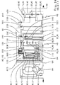
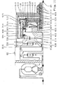
理解を深めるためにまず本発明の基礎となる技術の現状を説明する。図1AはDE10318565.8による前文に係る技術の現状のスケルトン図、図1Bは相応する作動表を示す。図1AにおいてANは自動変速機の駆動軸であり、自動変速機の(図示しない)原動機と作用結合され、図示例ではトルクコンバータを介してトーショナルダンパおよびコンバータロックアップクラッチと作用結合されている。ABは駆動軸ANと同軸に配置される自動変速機被動軸であり、自動車の少なくとも1つの駆動車軸と作用結合されている。勿論、トルクコンバータの代わりに摩擦クラッチも自動変速機の発進クラッチとして原動機と自動変速機との間に配置しておくことができよう。また、原動機は単に単一のトーショナルダンパまたは2質量フライホイールまたは剛性軸を介して変速機駆動軸ANと結合しておくことができよう。その場合、自動変速機の内部に配置される摩擦切換要素は変速機の発進要素として構成されていなければならない。 In order to deepen the understanding, the current state of the technology that forms the basis of the present invention will be described first. FIG. 1A shows a skeleton diagram of the state of the art according to the preamble according to DE 103188565.8, and FIG. 1B shows a corresponding operation table. In FIG. 1A, AN is a drive shaft of an automatic transmission, which is operatively coupled to a prime mover (not shown) of the automatic transmission, and in the illustrated example, is operatively coupled to a torsional damper and a converter lockup clutch. . AB is an automatic transmission driven shaft arranged coaxially with the drive shaft AN, and is operatively coupled to at least one drive axle of the automobile. Of course, instead of the torque converter, a friction clutch may be arranged between the prime mover and the automatic transmission as a starting clutch of the automatic transmission. Alternatively, the prime mover could simply be coupled to the transmission drive shaft AN via a single torsional damper or a two mass flywheel or rigid shaft. In that case, the friction switching element disposed inside the automatic transmission must be configured as a starting element of the transmission.
この自動変速機は前置歯車組VSと、同軸でこの前置歯車組VSの横に(但し直接横にではなく)配置された主歯車組HSとを有する。前置歯車組VSは二重遊星構造様式のプラス遊星歯車組として実施され、リングギヤHO−VSと太陽歯車SO−VSと2つの単一キャリヤで形成されるキャリヤST−VSとを有し、太陽歯車SO−VSにかみ合う内側遊星歯車P1−VSと、内側遊星歯車P1−VSおよびリングギヤHO−VSにかみ合う外側遊星歯車P2−VSが、このキャリヤで回転可能に支承されている。この前置歯車組VSは切換不可能な減速段として作動し、自動変速機駆動軸ANの入力回転数よりも小さな値の出力回転数を発生する。このため、前置歯車組VSの太陽歯車SO−VSが変速機ケースGGに固定され、キャリヤST−VSが駆動軸ANと常時結合されている。つまりリングギヤHO−VSは前置歯車組VSの出力要素を形成し、かつ2つの切換要素A、Bを介して主歯車組HSの個々の入力要素と結合可能である。 This automatic transmission has a front gear set VS and a main gear set HS which is coaxial and is arranged beside (but not directly beside) the front gear set VS. The front gear set VS is implemented as a double planetary gear set plus planetary gear set and has a ring gear HO - VS, a sun gear SO - VS and a carrier ST - VS formed by two single carriers, and VS, the inner planetary gear P1 - - gear sO - inner planetary gears meshing with the VS P1 VS and the ring gear HO - outer planetary gears meshing with the VS P2 - VS is rotatably supported by the carrier. This front gear set VS operates as a non-switchable reduction stage, and generates an output rotational speed that is smaller than the input rotational speed of the automatic transmission drive shaft AN. Therefore, the sun gear SO of the front置歯wheel sets VS - VS is fixed to the transmission case GG, carrier ST - VS is coupled constantly with the drive shaft AN. In other words, the ring gear HO - VS forms an output element of the front gear set VS and can be coupled to individual input elements of the main gear set HS via the two switching elements A and B.
主歯車組HSは、互いに連結されていない3つの入力要素と1つの出力要素とを有する連結された2キャリヤ‐4軸‐遊星歯車装置として構成され、ラビニヨ式歯車組の態様で2つの太陽歯車S1−HS、S2−HSとリングギヤHO−HSと連結されたキャリヤST−HSとを有し、第1太陽歯車S1−HSおよびリングギヤHO−HSにかみ合う長い遊星歯車P1−HSと、第2太陽歯車S2−HSおよび長い遊星歯車P1−HSにかみ合う短い遊星歯車P2−HSとがこのキャリヤで回転可能に支承されている。第1太陽歯車S1−HSが主歯車組HSの第1入力要素を形成し、第2太陽歯車S2−HSが主歯車組HSの第2入力要素を形成し、連結されたキャリヤST−HSが主歯車組HSの第3入力要素を形成し、リングギヤHO−HSが主歯車組HSの出力要素を形成する。 The main gear set HS is configured as a connected two-carrier four-axis-planetary gear set with three input elements and one output element that are not connected to each other, and in the form of a Ravigneaux gear set, two sun gears S1 - HS, S2 - HS and the ring gear HO - HS and linked carrier ST - and a HS, first sun gear S1 - long planetary gear P1 meshing with HS - - HS and the ring gear HO and HS, the second sun A gear S2 - HS and a short planetary gear P2 - HS meshing with the long planetary gear P1 - HS are rotatably supported by this carrier. The first sun gear S1 - HS forms the first input element of the main gear set HS, the second sun gear S2 - HS forms the second input element of the main gear set HS, and the coupled carrier ST - HS The third input element of the main gear set HS is formed, and the ring gear HO - HS forms the output element of the main gear set HS.
自動変速機は合計6つの切換要素A〜Fを有する。切換要素A、B、E、Fはクラッチとして構成され、切換要素C、Dはブレーキとして構成されている。このため主歯車組HSの第2太陽歯車S2−HSは第1切換要素Aを介して前置歯車組VSのリングギヤHO−VSと結合可能である。このためさらに、主歯車組HSの第1太陽歯車S1−HSは第2切換要素Bを介して前置歯車組VSのリングギヤHO−VSと結合可能、第3切換要素Cを介して変速機ケースGGに固定可能、かつ第6切換要素Fを介して駆動軸ANと結合可能である。このためさらに、主歯車組HSのキャリヤST−HSは第4切換要素Dを介して変速機ケースGGに固定可能、かつ第5切換要素Eを介して駆動軸ANと結合可能である。つまり個々の切換要素に対して主歯車組HSの個々の要素がこのように結合される結果、主歯車組HSのキャリヤST−HSは第5、第6切換要素E、Fを同時に係合させることによって主歯車組HSの第1太陽歯車S1−HSとも結合可能である。主歯車組HSのリングギヤHO−HSは常時、そして専ら、被動軸ABと結合されている。 The automatic transmission has a total of six switching elements AF. The switching elements A, B, E, and F are configured as clutches, and the switching elements C and D are configured as brakes. The second sun gear S2 of this for the main gearset HS - HS ring gear HO before置歯wheel sets VS via a first switching element A - is capable of binding to VS. The first sun gear S1 of this for further main gearset HS - HS ring gear HO of置歯wheel sets VS before via the second shifting element B - capable of binding to VS, the transmission case via the third shifting element C It can be fixed to GG and can be connected to the drive shaft AN via the sixth switching element F. Thus Furthermore, the main gearset HS carrier ST - HS is coupleable with the drive shaft AN via the fourth switching element via the D fixable to the transmission case GG, and the fifth shifting element E. That results individual elements of the main gearset HS for each switching element is coupled in this manner, the carrier ST main gearset HS - HS is engaged fifth, sixth shifting element E, F at the same time the first sun gear S1 of the main gearset HS by - with HS is capable of binding. Ring gear HO main gearset HS - HS is always and exclusively, combined with the driven shaft AB.
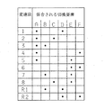
図1Bは図1Aに示す多段自動変速機の作動表を示す。合計8つの前進変速段がレンジシフトなしに切換可能であり、つまり或る変速段から次に高い変速段または次に低い変速段へと切換えるためにまさに操作された切換要素によってその都度単に1つの切換要素が開放され、他の1つの切換要素が係合する。第1変速段「1」ではクラッチAとブレーキDが係合し、第2変速段「2」ではクラッチAとブレーキCが係合し、第3変速段「3」ではクラッチA、Bが係合し、第4変速段「4」ではクラッチA、Fが係合し、第5変速段「5」ではクラッチA、Eが係合し、第6変速段「6」ではクラッチE、Fが係合し、第7変速段「7」ではクラッチB、Eが係合し、第8変速段「8」ではブレーキCとクラッチEが係合している。第1後退変速段「R1」ではクラッチBとブレーキDが係合している。第2後退変速段「R2」も設けておくことができ、そこではクラッチFとブレーキDが係合している。図1Cは図1Aに示す多段自動変速機の速度線図である。図1Cは図1Aに示す多段自動変速機の速度線図を示す。 FIG. 1B shows an operation table of the multi-stage automatic transmission shown in FIG. 1A. A total of eight forward gears can be switched without a range shift, i.e. just one each time by a switching element that has just been operated to switch from one gear to the next higher gear or the next lower gear. The switching element is released and the other switching element is engaged. At the first speed “1”, the clutch A and the brake D are engaged, at the second speed “2”, the clutch A and the brake C are engaged, and at the third speed “3”, the clutches A and B are engaged. The clutches A and F are engaged at the fourth speed “4”, the clutches A and E are engaged at the fifth speed “5”, and the clutches E and F are engaged at the sixth speed “6”. The clutches B and E are engaged at the seventh speed “7”, and the brake C and the clutch E are engaged at the eighth speed “8”. At the first reverse shift stage “R1”, the clutch B and the brake D are engaged. A second reverse gear stage “R2” can also be provided, in which the clutch F and the brake D are engaged. FIG. 1C is a speed diagram of the multi-stage automatic transmission shown in FIG. 1A. FIG. 1C shows a speed diagram of the multi-stage automatic transmission shown in FIG. 1A.
図1Aに立ち帰るなら、切換要素のディスク束、入力要素、出力要素は統一的に表してある。第1切換要素Aのディスク束は符号100、第1切換要素Aの入力要素は符号120、第1切換要素Aの出力要素は符号130、第1切換要素Aのディスク束100を操作するためのサーボ機構は符号110である。同様に、別の切換要素B、C、D、E、Fのディスク束は符号200、300、400、500、600、別の切換要素B、E、Fの入力要素は符号220、520、620である。同様に、別の切換要素B、C、D、E、Fの出力要素も符号230、330、430、530、630、別のクラッチB、E、Fの各ディスク束200もしくは500もしくは600を操作するためのサーボ機構は符号210、510、610である。
Returning to FIG. 1A, the disk bundle of switching elements, input elements, and output elements are shown in a unified manner. The disk bundle of the first switching element A is denoted by
符号GGとされた変速機ケースの内部での切換要素と歯車組との互いに相対的な空間的配置に関してDE10318565.8は以下の如く教示している:クラッチとして構成される第5切換要素Eは空間的に見て軸線方向において前置歯車組VSと主歯車組HSとの間に、軸線方向において前置歯車組VSに直接接して配置されている。やはりクラッチとして構成される第2切換要素Bはやはり軸線方向において前置歯車組VSと主歯車組HSとの間に配置されており、このクラッチBのディスク束200は空間的に見てクラッチEのディスク束500の概ね半径方向上に配置され、クラッチBのサーボ機構210は軸線方向において前置歯車組VSから離れた方の側でクラッチEに接している。軸線方向において主歯車組HSの方向に見てクラッチBに続くのはまず、ブレーキとして構成される第3切換要素C、次にやはりブレーキとして構成される第4切換要素D、次に主歯車組HSである。クラッチとして構成される第1切換要素Aのディスク束100は空間的に見て前置歯車組VSの概ね上に配置されている。このクラッチAのサーボ機構110は少なくとも十分に、主歯車組HSから離れた方の前置歯車組VSの側に配置されている。クラッチAの前置歯車組VSから離れた方のサーボ機構110の側に、空間的に見て軸線方向においてクラッチAと駆動側変速機ケース固定ケース壁GWとの間に、つまりクラッチAおよび前置歯車組VSの主歯車組HSから離れた方の側に、クラッチとして構成される第6切換要素Fは配置されている。
Regarding the spatial arrangement of the switching element and the gear set relative to each other inside the transmission case, designated GG, DE 103185655.8 teaches as follows: The fifth switching element E configured as a clutch is When viewed spatially, the front gear set VS and the main gear set HS are arranged in direct contact with the front gear set VS in the axial direction in the axial direction. The second switching element B, which is also configured as a clutch, is also disposed between the front gear set VS and the main gear set HS in the axial direction. The
1つの切換要素の1つのサーボ機構の実施例として図1Aには第6切換要素Fのサーボ機構610が詳しく示してある。このサーボ機構610が円筒状ディスク支持体の内部に配置されており、このディスク支持体はクラッチFの入力要素620を形成し、相応に変速機駆動軸ANの回転数で常に回転する。サーボ機構610が圧力室611を有し、この圧力室はクラッチFのディスク支持体の外被面区域とサーボ機構610のピストン614とによって形成される。この圧力室611に圧力が付加されるとピストン614はサーボ機構610のここで例示的に皿ばねとして構成される戻し要素613の力に抗して軸線方向において前置歯車組VSの方向に動き、クラッチFのディスク束600を操作もしくは係合させる。回転する圧力室611の動的圧力を主に完全に補償するために、サーボ機構610は付加的に潤滑剤を無圧充填可能な圧力補償室612を有し、この圧力補償室はピストン614の1つの面と堰円板615とによって形成される。入力要素620は変速機ケース固定ハブGN上で回転可能に支承されており、このハブは変速機ケース固定ケース壁GWから出発して変速機ケースGGの内部空間内で軸線方向において前置歯車組VSの方向に前置歯車組VSの太陽歯車SO−VSに至るまで延設され、相対回転不能にこの太陽歯車SO−VSと結合されている。同様に、この変速機ケース固定ハブGNはクラッチFの圧力室と圧力補償室とに圧媒もしくは潤滑剤を供給するための通路も有する。
As an example of one servomechanism for one switching element, FIG. 1A shows the
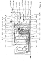
次に図2に基づいて本発明による例示的第1スケルトン図を説明する。図1による前文に係る技術の現状におけると同様に、本発明に係る自動変速機は駆動軸ANと、被動軸ABと、二重遊星構造様式の単一遊星歯車組として実施される前置歯車組VSと、互いに連結された遊星歯車組で形成される多部分構成の主歯車組HSと、6つの切換要素A〜Fとを有する。主に、これら6つの切換要素A〜Fのうちその都度2つの切換要素を選択的に係合させることによって駆動軸ANの回転数は歯車組VS、HSを介して少なくとも8つの異なる前進変速段に伝達可能であり、或る変速段から次に高い変速段または次に低い変速段へと段切替のたびに、常に1つのそれまで係合していた切換要素のみが開放され、それまで係合していない1つの切換要素が係合される。前置歯車組VSと主歯車組HSは互いに同軸に配置されている。駆動軸ANと被動軸ABは例示的に互いに同軸に延びているが、しかし比較的簡単な変更によって軸線平行または互いに角度を成して延びることもできる。切換要素A〜Fおよび駆動軸AN、被動軸ABに対する前置歯車組VSおよび主歯車組HSの運動学的連結は実質的に図1から引き継がれており、図2による本発明に係る変速機にも図1Bに示す切換ロジックがあてはまる。 An exemplary first skeleton diagram according to the present invention will now be described with reference to FIG. As in the state of the art according to the preamble according to FIG. 1, the automatic transmission according to the invention is a pregear gear implemented as a single planetary gear set in the form of a drive shaft AN, a driven shaft AB and a double planetary structure. It includes a set VS, a multi-part main gear set HS formed of planetary gear sets connected to each other, and six switching elements A to F. Mainly, by selectively engaging two of these six switching elements A to F each time, the rotational speed of the drive shaft AN is at least eight different forward shift speeds via the gear sets VS and HS. Each time the gear is switched from one gear position to the next higher gear position or the next lower gear position, only one of the switching elements that has been engaged is always released. One switching element that is not matched is engaged. The front gear set VS and the main gear set HS are arranged coaxially with each other. The drive shaft AN and the driven shaft AB illustratively extend coaxially with each other, but can also extend parallel to the axis or at an angle to each other with relatively simple modifications. The kinematic connection of the front gear set VS and the main gear set HS to the switching elements A to F, the drive shaft AN, the driven shaft AB is substantially taken over from FIG. 1, and the transmission according to the invention according to FIG. The switching logic shown in FIG. 1B also applies.
図1との細部の違いは主歯車組HSの構成に関係しており、この主歯車組はいまや例示的に、相互に独立した3つの入力要素と1つの出力要素とを有する「2キャリヤ‐ユニットに低減された3キャリヤ‐5軸‐遊星歯車装置」として実施されている。図2によるこの「新規な」主歯車組HSは互いに連結された3つの遊星歯車組で形成されており、これら3つの個々の遊星歯車組のうち2つはやはり1つの遊星歯車組としてまとめられ、その場合この遊星歯車組は残りの単一遊星歯車組と連結されている。「新規な」主歯車組HSは3つの太陽歯車S1−HS、S2−HS、S3−HSと単に2つのリングギヤH13−HS、H2−HSと単に2つのキャリヤST13−HS、ST2−HSとキャリヤでそれぞれ回転可能に支承された遊星歯車P13−HSもしくはP2−HSとを含む。第2太陽歯車S2−HSと第2キャリヤST2−HSと短い遊星歯車P2−HSと第2リングギヤH2−HSは主歯車組HSの残りの単一遊星歯車に付設されており、この短い遊星歯車P2−HSは主歯車組HSの第2太陽歯車S2−HSと第2リングギヤH2−HSとにかみ合う。連結キャリヤST13−HSの第1、第3太陽歯車S1−HS、S3−HSと、長い遊星歯車P13−HSと、連結リングギヤH13−HSは、主歯車組HSの連結遊星歯車組に付設されており、これらの長い遊星歯車P13−HSは主歯車組HSの両方の太陽歯車S1−HS、S3−HSと連結リングギヤH13−HSとにかみ合う。つまり主歯車組HSの前記連結遊星歯車組は基本的に、分割太陽歯車を有する単一遊星歯車組と理解することもできる。2つの個別太陽歯車(S1−HS、S3−HS)への前記太陽歯車のこの「分割」は、さまざまな切換要素A〜Fに対する主歯車組HSの入力要素の運動学的連結と、変速機被動軸ABに対する主歯車組HSの出力要素の運動学的連結を、図1による前文に係る技術の現状から設定されたように、いまや以下で説明する本発明に係る部材配置と合わせて具現できるようにするうえで重要である。第2太陽歯車S2−HSを有する主歯車組HSの単一遊星歯車組は空間的に見て主歯車組HSの遠前置歯車組側に配置されているのに対して、第3太陽歯車S3−HSは主歯車組HSの近前置歯車組側に配置されている。つまり主歯車組HSの第1太陽歯車S1−HSは軸線方向において主歯車組HSの別の太陽歯車S3−HS、S2−HSの間に配置されている。 The difference in detail with respect to FIG. 1 relates to the construction of the main gear set HS, which by way of example now has two input elements and one output element which are independent of each other, “2 carriers— It is implemented as a 3 carrier-5 shaft-planet gear unit reduced to unit. This “new” main gear set HS according to FIG. 2 is formed by three planetary gear sets connected to each other, two of these three individual planetary gear sets being combined together as one planetary gear set. In this case, this planetary gear set is connected to the remaining single planetary gear set. The “new” main gear set HS consists of three sun gears S1 - HS, S2 - HS, S3 - HS and just two ring gears H13 - HS, H2 - HS and just two carriers ST13 - HS, ST2 - HS and a carrier. And planetary gears P13 - HS or P2 - HS, each of which is rotatably supported. The second sun gear S2 - HS, the second carrier ST2 - HS, the short planetary gear P2 - HS, and the second ring gear H2 - HS are attached to the remaining single planetary gear of the main gear set HS. P2 - HS second sun gear S2 of the main gearset HS - HS and the second ring gear H2 - mesh with and HS. Connecting the carrier ST13 - first HS, third sun gear S1 - and HS, long planet gears P13 - - HS, S3 and HS, connecting the ring gear H13 - HS is being attached to the connecting planetary gearset of the main gearset HS cage, these long planet gears P13 - HS primarily gearset HS of both sun gears S1 - HS, S3 - HS consolidated ring gear H13 - mesh with and HS. That is, the connecting planetary gear set of the main gear set HS can be basically understood as a single planetary gear set having divided sun gears. This "split" of the sun gear into two individual sun gears (S1 - HS, S3 - HS) is the kinematic connection of the input elements of the main gear set HS to the various switching elements AF and the transmission The kinematic connection of the output element of the main gear set HS to the driven shaft AB can now be implemented in combination with the arrangement of the components according to the invention described below, as set from the state of the art according to the preamble according to FIG. Is important in doing so. The single planetary gear set of the main gear set HS having the second sun gear S2 - HS is arranged on the far front gear set side of the main gear set HS in terms of space, whereas the third sun gear S3 - HS is arranged on the near front gear set side of the main gear set HS. In other words, the first sun gear S1 - HS of the main gear set HS is disposed between the other sun gears S3 - HS, S2 - HS of the main gear set HS in the axial direction.
前置歯車組VSは図1と同様に太陽歯車SO−VSと、連結キャリヤST−VSと、このキャリヤで回転可能に支承される内側および外側遊星歯車P1−VS、P2−VSと、リングギヤHO−VSとを含む。太陽歯車SO−VSは変速機ケースGGと相対回転不能に結合されたハブGNに固定されており、このハブは変速機ケース固定ケース壁GWから出発して変速機内部空間内を前置歯車組VSの方向に延設されている。前記ケース壁GWがここでは変速機の外壁を形成し、この外壁は一方で主歯車組HSから離れた方の前置歯車組VSの側に配置され、他方で、駆動軸ANに作用結合されたここでは簡略のため詳しくは図示しない変速機原動機に向き合っている。図2に示すスケルトン図において例示的にトルクコンバータはパワーフロー方向において原動機と駆動軸ANとの間に配置されている。連結キャリヤST−VSが前置歯車組VSの入力要素を形成し、このキャリヤST−VSの主歯車組HSに向き合うキャリヤ板は変速機の駆動軸ANと相対回転不能に結合されている。リングギヤHO−VSは前置歯車組VSの出力要素を形成し、駆動軸ANの回転数よりも小さな回転数で回転し、駆動軸ANの回転と同じ回転方向を有する。前置歯車組VSのこの出力回転数は第1、第2切換要素A、Bを介して主歯車組HSの2つの異なる入力要素に伝達可能である。 As in FIG. 1, the front gear set VS includes a sun gear SO - VS, a connecting carrier ST - VS, inner and outer planetary gears P1 - VS, P2 - VS rotatably supported by this carrier, and a ring gear HO. - and a VS. The sun gear SO - VS is fixed to a hub GN that is non-rotatably coupled to the transmission case GG. This hub starts from the transmission case fixing case wall GW and moves in the transmission internal space to the front gear group. It extends in the direction of VS. The case wall GW here forms the outer wall of the transmission, which is arranged on the one hand on the front gear set VS side away from the main gear set HS and on the other hand is operatively coupled to the drive shaft AN. Here, for simplification, it faces a transmission prime mover (not shown in detail). In the skeleton diagram shown in FIG. 2, the torque converter is exemplarily arranged between the prime mover and the drive shaft AN in the power flow direction. The connecting carrier ST - VS forms an input element of the front gear set VS, and the carrier plate facing the main gear set HS of the carrier ST - VS is coupled to the drive shaft AN of the transmission so as not to be relatively rotatable. The ring gear HO - VS forms an output element of the front gear set VS, rotates at a rotational speed smaller than the rotational speed of the drive shaft AN, and has the same rotational direction as the rotation of the drive shaft AN. This output speed of the front gear set VS can be transmitted to two different input elements of the main gear set HS via the first and second switching elements A, B.
主歯車組HSの第1、第2太陽歯車S1−HS、S2−HSは互いに相対回転不能に結合され、主歯車組HSの第1入力要素を形成し、ここでディスククラッチとして構成される第2切換要素Bを介して前置歯車組VSの出力要素‐つまりリングギヤHO−VS‐と結合可能である。主歯車組HSの第2リングギヤH2−HSは主歯車組HSの第2入力要素を形成し、ここでディスククラッチとして構成される第1切換要素Aを介してやはり前置歯車組VSの出力要素‐つまりリングギヤHO−VS‐と結合可能である。主歯車組HSの連結キャリヤST13−HSは主歯車組HSの第3入力要素を形成し、一方でここでディスククラッチとして構成される第5切換要素Eを介して駆動軸ANと結合可能、他方で選択的にここで例示的にディスクブレーキとして構成される第4切換要素Dを介して変速機ケースGGに固定可能でもある。主歯車組HSの第3太陽歯車S3−HSは主歯車組HSの第4入力要素を形成し、一方でここでディスククラッチとして構成される第6切換要素Fを介して駆動軸ANと結合可能、他方で選択的にここで例示的にディスクブレーキとして構成される第3切換要素Cを介して変速機ケースGGに固定可能でもある。主歯車組HSの連結リングギヤH13−HSと第2キャリヤST2−HSは相対回転不能に互いに結合され、主歯車組HSの出力要素を形成し、変速機の被動軸ABと結合されている。 The first and second sun gears S1 - HS, S2 - HS of the main gear set HS are coupled to each other such that they cannot rotate relative to each other, and form a first input element of the main gear set HS, which is configured as a disc clutch. It is possible to couple with the output element of the front gear set VS, that is, the ring gear HO - VS-, via the two switching elements B. The second ring gear H2 - HS of the main gear set HS forms the second input element of the main gear set HS, and here again the output element of the front gear set VS via the first switching element A configured as a disc clutch. -That is, it can be coupled with the ring gear HO - VS-. The coupling carrier ST13 - HS of the main gear set HS forms the third input element of the main gear set HS, which can be coupled to the drive shaft AN via a fifth switching element E, which here is configured as a disc clutch, It can also be fixed to the transmission case GG selectively via a fourth switching element D which is here exemplified as a disc brake. The third sun gear S3 - HS of the main gear set HS forms the fourth input element of the main gear set HS, which can be connected to the drive shaft AN via a sixth switching element F, which is here configured as a disc clutch. On the other hand, it can also be fixed to the transmission case GG selectively via a third switching element C which is here exemplified as a disc brake. The connecting ring gear H13 - HS and the second carrier ST2 - HS of the main gear set HS are coupled to each other so as not to rotate relative to each other, form an output element of the main gear set HS, and are coupled to the driven shaft AB of the transmission.
主歯車組HSの構造と個々の切換要素A〜Fに対するその運動学的連結から明らかとなるように、図1とは異なり図2では、3つの切換要素B、C、Fの出力要素230、330、630と主歯車組HSの第1入力要素(つまり図1では太陽歯車S1−HS)との間に図1では存在した固定連結が、クラッチBの出力要素230と主歯車組HSの第1入力要素(つまり図2では連結太陽歯車S1−HS、S2−HS)との間の固定連結と、ブレーキCの出力要素330およびクラッチFの出力要素630と主歯車組HSの第4入力要素(つまり図2では太陽歯車S3−HS)との間の固定連結と、主歯車組HSの長い遊星歯車P13−HSを介した主歯車組HSの第1、第4入力要素の間の運動学的連結との組合せに取替えられている。相応に図2によれば本発明に係る変速機の速度線図において主歯車組HSの第1入力要素の線と第4入力要素の線は一致する。主歯車組HSの1変更態様において、前記長い遊星歯車P13−HSが図2の図示から離れて多段遊星歯車として構成することが予定される場合、この変更態様に付属する速度線図において変更主歯車組の第1入力要素の線と第4入力要素の線は互いに隣接することになろう。
As will become clear from the structure of the main gear set HS and its kinematic connection to the individual switching elements A to F, unlike FIG. 1, in FIG. 2, the
本発明によれば第5、第6切換要素E、Fは製造技術上簡単に予め組付可能な構造群を形成し、この構造群は第5、第6切換要素E、Fに共通するディスク支持体ZYLEFと、第5、第6切換要素E、F用のディスク束500、600と、第5、第6切換要素E、Fの各ディスク束500、600を操作するための第5、第6切換要素E、F用の各1つのサーボ機構510、610とを含む。両方の切換要素E、Fに共通するディスク支持体ZYLEFはクラッチEの入力要素520もクラッチFの入力要素620も形成する。図2で明らかとなるように、両方のクラッチE、Fを有するこの構造群は空間的に見て主歯車組HSから離れた方の前置歯車組VSの側に配置されている。特に前置歯車組VSとクラッチE、Fのディスク束500、600の幾何学的設計に応じて、クラッチE、Fを含む構造群の別の1構成において、クラッチE、Fのディスク束500、600が図2の図示から離れて部分的にまたは完全にも前置歯車組VSの半径方向上の領域に配置することを予定することもでき、しかしその場合、クラッチE、Fを含む構造群の主要部材は‐特にクラッチE、Fのサーボ機構510、610は‐いまなお少なくとも十分に、主歯車組HSから離れた方の前置歯車組VSの側に配置されている。
According to the present invention, the fifth and sixth switching elements E and F form a structural group that can be easily assembled in advance in terms of manufacturing technology, and this structural group is a disk common to the fifth and sixth switching elements E and F. The fifth and
図2でさらに明らかとなるように、ここでディスククラッチとして構成される第1切換要素Aとやはりここでディスククラッチとして構成される第2切換要素Bは両方のクラッチE、Fを有する構造群とは反対の前置歯車組VSの側に、空間的に見て軸線方向において前置歯車組VSと主歯車組HSとの間の領域に配置されている。クラッチAはクラッチBよりも前置歯車組VS近傍に配置されており、クラッチAはここでは軸線方向において主歯車組HSに向き合う側で前置歯車組VSに直接接し、クラッチBは軸線方向において主歯車組HSに向き合う香川でクラッチAに直接接している。両方のクラッチA、Bのディスク束100、200は例示的に同じ直径に配置されており、そのことからこれらのクラッチA、B用に同じディスクを使用することが可能となる。クラッチAの入力要素120は例示的に円筒環状外ディスク支持体として構成され、この外ディスク支持体は一方でその近前置歯車組側末端をリングギヤHO−VSと相対回転不能に結合され、他方でその近主歯車組側末端の領域でその内径に、クラッチAのディスク束100の例えば外歯覆いディスクとして構成される外ディスクを受容するための好適な連行断面を有する。クラッチBの入力要素220は例示的にやはり円筒環状外ディスク支持体として構成され、その近主歯車組側末端の領域でその内径に、クラッチBのディスク束200の例えば外歯覆いディスクとして構成される外ディスクを受容するための好適な連行断面を有する。クラッチAもしくは前置歯車組VSに向き合うその末端でクラッチBの入力要素220はクラッチAの入力要素120と相対回転不能に結合され、つまりクラッチAの入力要素120を介して前置歯車組VSのリングギヤHO−VSと結合されている。勿論、これら両方の入力要素120、220は一体に実施しておくこともできる。両方のクラッチA、Bの出力要素130、230は相応に内ディスク支持体として構成され、それらの外径には、各ディスク束100もしくは200の例えば内歯鋼ディスクとして構成される内ディスクを受容するための好適な連行断面をそれぞれ有する。その際、クラッチAの十分に円板状に構成される内ディスク支持体130は前置歯車組VSと概ね平行に延設され、そのハブ領域で第2太陽歯車軸140と相対回転不能に結合されている。この第2太陽歯車軸140自体はクラッチAから出発して軸線方向において主歯車組HSの方向に延設され、その推移においてクラッチAの横に配置されるクラッチBにも主歯車組HSにも中心で完全に挿通され、主歯車組HSの遠前置歯車組側で主歯車組HSの第2リングギヤH2−HSと相対回転不能に結合されている。知られているように前記リングギヤH2−HSは主歯車組HSの第2入力要素を形成する。クラッチBのやはり十分に円板状に構成される内ディスク支持体230はクラッチAの内ディスク支持体130と概ね平行に延設され、そのハブ領域で第1太陽歯車軸240と相対回転不能に結合されている。この第1太陽歯車軸240はそれ自体クラッチBから出発して軸線方向において主歯車組HSの方向に延設され、その軸線方向推移において主歯車組HSの近前置歯車組側第3太陽歯車S3−HSに中心で完全に挿通され、第2太陽歯車軸140を半径方向で取り囲み、主歯車組HSの両方の連結太陽歯車S1−HS、S2−HSと結合されている。知られているように前記連結太陽歯車S1−HS、S2−HSは主歯車組HSの第1入力要素を形成する。
As will become more apparent in FIG. 2, the first switching element A, which is here configured as a disk clutch, and the second switching element B, which is also configured here as a disk clutch, are a group of structures having both clutches E, F; Is arranged on the opposite front gear set VS side in a region between the front gear set VS and the main gear set HS in the axial direction when viewed spatially. The clutch A is arranged closer to the front gear set VS than the clutch B. Here, the clutch A is in direct contact with the front gear set VS on the side facing the main gear set HS in the axial direction, and the clutch B is in the axial direction. It is in direct contact with the clutch A at Kagawa facing the main gear set HS. The disk bundles 100, 200 of both clutches A, B are illustratively arranged with the same diameter, which allows the same disk to be used for these clutches A, B. The
クラッチAのディスク束100を操作するためのサーボ機構110と、クラッチBのディスク束200を操作するためのサーボ機構210は、図2では簡略のため略示してあるだけである。その際、クラッチAのサーボ機構110は軸線方向において前置歯車組VSとクラッチAの出力要素130もしくは内ディスク支持体との間に配置され、例示的にクラッチAのこの出力要素もしくは内ディスク支持体で軸線方向摺動可能に支承されている。クラッチAが係合するとこのサーボ機構110は自己に付設されたディスク束100を軸線方向において主歯車組HSの方向に操作する。有意義には、サーボ機構110は主歯車組HSの第2入力要素の回転数、つまりここではリングギヤH2−HSの回転数で常に回転する圧力室の回転圧力を補償するための動的圧力補償部も有する。クラッチBのサーボ機構210はここで例示的にクラッチBのディスク束200のクラッチAもしくは前置歯車組VSとは反対の側に配置され、クラッチBの出力要素230もしくは内ディスク支持体で軸線方向摺動可能に支承されている。クラッチBが係合するとこのサーボ機構210は自己に付設されたディスク束200を軸線方向において前置歯車組VSの方向に操作する。有意義には、サーボ機構210は主歯車組HSの第1入力要素の回転数、つまりここでは両方の太陽歯車S1−HS、S2−HSの回転数で常に回転する圧力室の回転圧力を補償するための動的圧力補償部も有する。
The
図2でさらに明らかとなるように、ここで例示的にディスクブレーキとして構成される第3切換要素Cも、ここで例示的にディスクブレーキとして構成される第4切換要素Dも、両方のクラッチE、Fを有する構造群とは反対の前置歯車組VSの側に、空間的に見て軸線方向においてクラッチBと主歯車組HSとの間の領域に配置されている。ブレーキDはブレーキCよりも主歯車組HS近傍に配置されている。ブレーキCのディスク束300を操作するためのサーボ機構310と、ブレーキDのディスク束400を操作するためのサーボ機構410は、図2では簡略のため略示されているだけであり、空間的に見て軸線方向において両方のディスク束300、400の間に配置され、変速機ケースGGの相応するピストン室内で軸線方向摺動可能に支承されている。両方のブレーキC、Dの外ディスク支持体は例示的に変速機ケースGGに一体化されている。勿論当業者は、必要なら、両方のブレーキC、Dの一方または両方のためにそれぞれ個別の外ディスク支持体または両方のブレーキC、Dに共通する外ディスク支持体も設けることになり、その場合外ディスク支持体は個別の部材として相対回転不能に変速機ケースGGと結合されている。勿論当業者は、必要なら、個別の外ディスク支持体を有する各ブレーキに付設されるサーボ機構も前記個別の外ディスク支持体に一体化することになる。ブレーキCの出力要素330がここでは十分に円板状の内ディスク支持体として構成されている。この内ディスク支持体は空間的に見てブレーキCのディスク束300の内径から出発して半径方向内方に延設され、そのハブ領域で第3太陽歯車軸640と相対回転不能に結合されている。この第3太陽歯車軸640はブレーキCの出力要素330と主歯車組HSの近前置歯車組側第3太陽歯車S3−HSとの機械的結合を実現し、キャリヤ軸540の軸線方向区域を半径方向で取り囲む。太陽歯車軸640と太陽歯車S3−HSは一体に実施しておくこともできる。ブレーキDの出力要素430がここではやはり十分に円板状の内ディスク支持体として構成されている。この内ディスク支持体は空間的に見てブレーキDのディスク束400の内径から出発して半径方向内方に、主歯車組HSの連結キャリヤST13−HSの近前置歯車組側キャリヤ板に至るまで延設され、このキャリヤ板とも相対回転不能に結合されている。内ディスク支持体430とキャリヤST13−HSの近前置歯車組側キャリヤ板は一体に実施しておくこともできる。
As will become more apparent in FIG. 2, both the third switching element C, here illustratively configured as a disc brake, and the fourth switching element D, illustratively configured here as a disc brake, both clutches E , F is disposed on the side of the front gear set VS opposite to the structural group having F, in the region between the clutch B and the main gear set HS in the axial direction when viewed spatially. The brake D is arranged closer to the main gear set HS than the brake C. The
勿論当業者は、必要なら、変速機ケース内部での両方のブレーキC、Dの空間的位置も変更することになり、図2の図示から離れて、ブレーキCは例えばケース壁GWの領域に配置され、および/またはブレーキDは例えば主歯車組HSの半径方向上の領域に配置されている。 Of course, those skilled in the art will also change the spatial positions of both brakes C, D within the transmission case, if necessary, apart from the illustration of FIG. 2, the brakes C are arranged, for example, in the region of the case wall GW. And / or the brake D is arranged, for example, in a region in the radial direction of the main gear set HS.
両方のクラッチE、Fによって形成される構造群に立ち返って、図2で明らかとなるように、クラッチE、Fに共通するディスク支持体ZYLEFは両方のクラッチE、F用にそれらの入力要素を形成し、相応に駆動軸ANと相対回転不能に結合されている。ディスク支持体ZYLEFはクラッチE用にクラッチEのディスク束500の例えば外歯鋼ディスクとして構成される外ディスクを受容するための外ディスク支持体として構成され、クラッチF用にはクラッチFのディスク束600の例えば内歯覆いディスクとして構成される内ディスクを受容するための内ディスク支持体として構成されている。クラッチFのディスク束600は空間的に見てクラッチEのディスク束500の半径方向上の領域に配置されており、半径方向内側のディスク束500は軸線方向において前置歯車組VSの直接横に、特に軸線方向において前置歯車組VSのリングギヤHO−VSの直接横に配置されている。勿論、鋼ディスク(摩擦ライニングなし)と覆いディスクとの交互配置の代わりに、片側に摩擦ライニングを被着した鋼ディスクも使用することができ、その場合それぞれ外歯を取付けた鋼ディスクと内歯を取付けた鋼ディスクを交互に組立てて1つのディスク束としなければならない。提案された鋼ディスクの代わりに、カーボンまたは炭素繊維または別の好適な複合材料からなるディスクも勿論使用することができる。幾何学的には、前記ディスク支持体ZYLEFは実質的に前置歯車組VSの方向に開口した鉢体の態様に構成されている。クラッチEのディスク束500の外ディスクはディスク支持体ZYLEFの多段円筒状区域521の内径に配置されている。ディスク支持体ZYLEFの少なくとも十分に円板状の区域(鉢底)522はディスク支持体ZYLEFの前記円筒状区域521に続き、円筒状区域521の遠前置歯車組側末端から出発して半径方向内方に延設されている。ディスク支持体ZYLEFの前記鉢底(522)の内径にディスク支持体ZYLEFのハブが続いている。クラッチEに付設されたディスク支持体ZYLEFの第1ハブ区域523は前記鉢底(522)の内径から出発して軸線方向において前置歯車組VSの方向に延設されている。この第1ハブ区域523はその近前置歯車組側末端で前置歯車組VSの連結キャリヤST−VSの遠主歯車組側キャリヤ板と相対回転不能に結合されており、このキャリヤST−VSの近主歯車組側キャリヤ板は相対回転不能に駆動軸ANと結合されている。クラッチFに付設されるべきディスク支持体ZYLEFの第2ハブ区域623はディスク支持体ZYLEFの円板状区域522もしくは鉢底の内径から出発して軸線方向において前置歯車組VSとは逆方向に、もしくは軸線方向においてケース壁GWの方向に延設されている。ディスク支持体ZYLEFのハブはそのハブ区域523、623が変速機ケース固定ハブGNで回転可能に支承されており、この固定ハブに前置歯車組VSの太陽歯車SO−VSも固定されている。符号621はディスク支持体ZYLEFの円筒状区域521の外径であり、この区域がクラッチFにも付設されることを指摘するものである。つまりこの外径にはクラッチFのディスク束600の内ディスクを受容するための連行断面が設けられている。
Returning to the structure formed by both clutches E, F, as will be apparent in FIG. 2, the disk support ZYLEF common to clutches E, F has their input elements for both clutches E, F. And correspondingly non-rotatably coupled with the drive shaft AN. The disk support ZYLEF is configured as an outer disk support for receiving an outer disk configured as, for example, an external steel disk of the
クラッチEのディスク束500を操作するためのサーボ機構510は圧力室511と圧力補償室512とピストン514と戻し要素513と堰円板515とを含み、ディスク支持体ZYLEFの第1ハブ区域523の半径方向上方、ディスク支持体ZYLEF、特にその円筒状区域521によって形成される円筒室の完全に内部に配置されている。ピストン514はこのディスク支持体ZYLEFで軸線方向摺動可能に支承されている。相応にサーボ機構510は駆動軸ANの回転数で常時回転する。サーボ機構510の回転する圧力室511の回転圧力を補償するために、潤滑剤を無圧充填可能な圧力補償室512での動的圧力補償が予定されており、この圧力補償室512は前記圧力室511よりも主歯車組HS近傍に配置されている。圧力室511はディスク支持体ZYLEFの外被面とピストン514とによって形成される。圧力補償室512はピストン514と堰円板515とによって形成され、この堰円板は軸線方向においてディスク支持体ZYLEFのハブ区域523に固定され、ピストン515に対して軸線方向摺動可能に潤滑剤密に密封されている。ピストン514は、ここで例示的に皿ばねとして構成される戻し要素513を介して軸線方向においてディスク支持体ZYLEFのハブ区域523の方向に付勢されている。クラッチEを係合させるために圧力室511に圧媒が付加されるとピストン514は軸線方向において前置歯車組VSの方向もしくは軸線方向において主歯車組HSの方向に移動し、自己に付設されたディスク束500を戻し要素513のばね力に抗して操作する。
The
空間的に見てクラッチEのサーボ機構510はクラッチFのサーボ機構610よりも主歯車組HS、前置歯車組VS近傍に配置されている。このサーボ機構610は空間的に見て少なくとも十分にディスク支持体ZYLEFの第2ハブ区域623の半径方向上の領域に配置され、ディスク支持体ZYLEFでも軸線方向摺動可能に支承されている。相応にサーボ機構610も駆動軸ANの回転数で常時回転する。クラッチFのサーボ機構610は圧力室611と圧力補償室612と一部で蛇行構成されたピストン614と戻し要素613と円筒状堰円板615と鉢状支持円板618とを含む。サーボ機構610の回転する圧力室611の回転圧力を補償するために、圧力補償室612での動的圧力補償が予定されている。このため円筒状堰円板615はハブ区域623の上方の限定的直径で、ディスク支持体ZYLEFの円板状区域522から出発して軸線方向においてケース壁GWの方向に延設され、軸線方向で隣接するピストン614の方に軸線方向摺動可能に潤滑剤密に密封されている。堰円板615の半径方向下方にあってケース壁GWに向き合うディスク支持体ZYLEFの外被面区域、および堰円板615の半径方向下方にあって前置歯車組VSに向き合うピストン614の外被面区域と一緒に、この堰円板615は前記圧力補償室612を形成する。図示例において堰円板615とディスク支持体ZYLEFは例示的に一体に実施されているが、しかし勿論個別の部材として実施しておくこともできる。つまりクラッチFのサーボ機構610の圧力補償室612と、クラッチEのサーボ機構510の圧力室511は互いに直接隣接して配置され、クラッチE、Fに共通するディスク支持体ZYLEFの外被面のみによって相互に分離されている。圧力室511もしくは前置歯車組VSから離れた方の圧力補償室612の側にサーボ機構610の圧力室611が配置されている。この圧力室611はピストン615と支持円板618とハブ623の軸線方向区域とによって形成される。このため支持円板618は圧媒密にハブ623に固着されている。ハブ623の圧力室611を形成する区域の半径方向上方でこの鉢状支持円板618の円筒状区域は軸線方向において圧力室511の方向にもしくは軸線方向において前置歯車組VSの方向に延設され、ピストン614の対応する区域に向かって圧媒密に軸線方向摺動可能に密封されている。そのさらなる幾何学的推移においてピストン614は少なくとも十分に支持円板618の外輪郭とディスク支持体ZYLEFの上側領域とに沿って半径方向外方に、軸線方向において主歯車組HSの方向に、クラッチFの自己に付設されたディスク束600の遠主歯車組側に至るまで延設されている。ピストン614を軸線方向で付勢する戻し要素613はここで例示的に、軸線方向においてディスク支持体ZYLEFの円板状区域622とピストン614との間に配置される、環状に配置されて運動学的に並列に接続された巻渦ばねからなる渦巻ばね束として構成されている。クラッチFを係合させるために圧力室611に圧媒が付加されるとピストン614は軸線方向において前置歯車組VSの方向もしくは軸線方向において主歯車組HSの方向に移動し、自己に付設されたディスク束600を戻し要素613のばね力に抗して操作する。
The
ディスク支持体ZYLEFが変速機ケース固定ハブGNで支承されているので、両方のクラッチE、Fへの圧媒および潤滑剤供給は相応する通路もしくは穴を介して設計上比較的簡単に得られる。これらの通路もしくは穴は一部では前記変速機ケース固定ハブGNの内部、一部ではディスク支持体ZYLEFのハブの内部を延びている。符号516はクラッチEのサーボ機構510の圧力室511に至る圧媒供給部、符号517はクラッチEのサーボ機構510の圧力補償室512に至る潤滑剤供給部、符号616はクラッチFのサーボ機構610の圧力室611に至る圧媒供給部、符号617はクラッチFのサーボ機構610の圧力補償室612に至る潤滑剤供給部である。
Since the disc support ZYLEF is supported by the transmission case fixing hub GN, the supply of pressure medium and lubricant to both clutches E, F can be obtained relatively easily by design via the corresponding passages or holes. These passages or holes extend partially inside the transmission case fixing hub GN and partially inside the hub of the disk support ZYLEF.
クラッチEの出力要素530は内ディスク支持体として構成され、クラッチEのディスク束500から出発して軸線方向においてクラッチEのサーボ機構510に接してまず軸線方向において前置歯車組VSの方向に、この前置歯車組VSのリングギヤのすぐ前で半径方向外方に、前記リングギヤHO−VSの外径のすぐ上方にまで、もしくはクラッチAの前記リングギヤHO−VSに結合された入力要素120の外径のすぐ上方に至るまで延設されている。クラッチEの内ディスク支持体530はその外径の領域で円筒状結合領域ZYLと相対回転不能に結合されている。この円筒状結合要素ZYLはクラッチEの方向で開口した鉢体として構成されている。この鉢体は前置歯車組VSと、軸線方向において前置歯車組VSに続くクラッチAと、軸線方向においてクラッチAに続くクラッチBとを半径方向で完全に取り囲む。この結合要素ZYLの円板状鉢底はこの場合軸線方向においてクラッチBのサーボ機構210に続き、その内径もしくはそのハブの領域でキャリヤ軸540と相対回転不能に結合されている。キャリヤ軸540はそれ自体軸線方向において主歯車組HSの方向に、主歯車組HSの近前置歯車組側第3太陽歯車S3−HSと空間的に中央の第1太陽歯車S1−HSとの間の領域にまで延設され、主歯車組HSの第3太陽歯車S3−HSに挿通され、主歯車組HSの連結キャリヤST13−HSと相対回転不能に結合されている。その限りで、前記円筒状結合要素ZYLは外面的にもクラッチEの出力要素530に付設することができる。
The
クラッチFの出力要素630は外ディスク支持体として構成され、幾何学的にはクラッチFもしくはケース壁GWの方向で開口した鉢体の形状であり、前記円筒状結合要素ZYLを半径方向で完全に取り囲む。クラッチFのこの出力要素630もしくは外ディスク支持体の円板状鉢底は空間的に見て軸線方向において前記結合要素ZYLの鉢底とブレーキCの円板状出力要素330もしくは内ディスク支持体との間で半径方向に延設され、そのハブ領域で第3太陽歯車軸640と相対回転不能に結合されている。この太陽歯車軸はブレーキCの出力要素330もしくは内ディスク支持体と主歯車組の第3太陽歯車S3−HSとも相対回転不能に結合されている。クラッチFの出力要素630もしくは外ディスク支持体の円筒状区域はクラッチFの出力要素630もしくは外ディスク支持体の鉢底の外径に続き、軸線方向においてケース壁GWの方向に、クラッチFのディスク束600の上にまで延設されている。出力要素もしくは外ディスク支持体630の前記円筒状区域はそのケース壁側末端の領域においてその内径に、クラッチFのディスク束600の外歯ディスクを受容するための好適な連行断面を有する。
The
次に、図3を基に本発明による例示的第2スケルトン図を説明する。これは先に図2に基づいて詳しく説明した本発明に係る第1変速機に基づいているが、但し第5、第6切換要素E、Fを有する構造群は図2に対して選択的設計構成を有する。図3による本発明に係る第2スケルトン図と図2による本発明に係る第1スケルトン図との間の本質的違いは、両方のブレーキE、Fのディスク束500、600の互いに相対的な空間的配置である。図3によれば、クラッチEのディスク束500はいまやクラッチFのディスク束600の半径方向上に配置されている。この配置に相応して両方のクラッチE、Fのサーボ機構510、610の空間的位置も適合されており、クラッチFのサーボ機構610はいまやクラッチEのサーボ機構510よりも前置歯車組VS近傍に配置されている。図3と基礎となる図2とを直接比較して容易に明らかとなるように、両方のクラッチE、Fの構造群全体は部材側で同一に構成されており、部材名のみが変更された。図2において殊にクラッチEに付設されたこれら構造群の全部品が図3ではいまやクラッチFに付設されている。相応に、図2において殊にクラッチFに付設されたこれら構造群の全部品が図3ではいまやクラッチEに付設されている。その限りで、両方のクラッチE、Fに共通するディスク支持体ZYLEFと両方のクラッチE、Fのサーボ機構510、610およびディスク束500、600とを有する構造群の他の説明は趣旨上適合された符号を指示することに限定することができる。
Next, an exemplary second skeleton diagram according to the present invention will be described with reference to FIG. This is based on the first transmission according to the present invention described in detail with reference to FIG. 2, except that the structure group having the fifth and sixth switching elements E, F is selectively designed with respect to FIG. It has a configuration. The essential difference between the second skeleton diagram according to the invention according to FIG. 3 and the first skeleton diagram according to the invention according to FIG. 2 is the relative space between the disk bundles 500, 600 of both brakes E, F. It is an ideal arrangement. According to FIG. 3, the
図3によればクラッチEのディスク束500が図2とは異なりクラッチFのディスク束600の半径方向上に配置されているので、クラッチFのいまや内ディスク支持体として構成される出力要素630もいまやクラッチEの出力要素530の内部に配置されている。クラッチFの前記出力要素630は軸線方向において前置歯車組VSおよび両方のクラッチA、Bを半径方向で取り囲み、軸線方向においてクラッチBの出力要素230の横で第1太陽歯車軸240と相対回転不能に結合されている。この第1太陽歯車軸240はそれ自体その軸線方向推移において主歯車組HSの近前置歯車組側第3太陽歯車S3−HSに挿通され、クラッチAの出力要素130とリングギヤH2−HSによって形成される主歯車組HSの第2入力要素との間に機械的結合を実現する第2太陽歯車軸140を半径方向で取り囲み、主歯車組の両方の連結太陽歯車S1−HS、S2−HSと相対回転不能に結合されている。クラッチEのいまや外ディスク支持体として構成される出力要素530は軸線方向においてクラッチFの出力要素630もしくは内ディスク支持体を半径方向で取り囲み、キャリヤ軸540を介して主歯車組HSの連結キャリヤST13−HSと結合されている。このキャリヤ軸540はその軸線方向推移において主歯車組HSの近前置歯車組側第3太陽歯車S3−HSに挿通され、第1太陽歯車軸240を半径方向で取り囲む。軸線方向において主歯車組HSの近前置歯車組側第3太陽歯車S3−HSと空間的見て中央の第1太陽歯車S1−HSとの間の領域でキャリヤ軸540は主歯車組HSの連結キャリヤST13−HSの近前置歯車組側キャリヤ板と相対回転不能に結合されており、前記キャリヤ板は軸線方向において両方の太陽歯車S3−HS、S1−HSの間で半径方向に挿通されている。ブレーキCの出力要素330はいまや単独で主歯車組HSの第3太陽歯車S3−HSと相対回転不能に結合されている。
According to FIG. 3, since the
図3に示す主歯車組HSの構造と個々の切換要素A〜Fに対するその運動学的連結から明らかとなるように、図1とは異なり図3では、3つの切換要素B、C、Fの出力要素230、330、630と主歯車組HSの第1入力要素(つまり図1では太陽歯車S1−HS)との間に図1では存在した固定連結が、クラッチBの出力要素230とクラッチFの出力要素630と主歯車組HSの第1入力要素(つまり図3では連結太陽歯車S1−HS、S2−HS)との間の固定連結と、ブレーキCの出力要素330と主歯車組HSの第4入力要素(つまり図3では太陽歯車S3−HS)との間の固定連結と、主歯車組HSの長い遊星歯車P13−HSを介した主歯車組HSの第1、第4入力要素の間の運動学的連結との組合せに取替えられている。相応に図3による本発明に係る変速機の速度線図において主歯車組HSの第1入力要素の線と第4入力要素の線は一致する。主歯車組HSの1変更態様において、前記長い遊星歯車P13−HSが図3の図示から離れて多段遊星歯車として構成することが予定される場合、この変更態様に付属する速度線図において変更主歯車組の第1入力要素の線と第4入力要素の線は互いに隣接することになろう。
As will be apparent from the structure of the main gear set HS shown in FIG. 3 and its kinematic connection to the individual switching elements A to F, FIG. 3 differs from FIG. 1 in that the three switching elements B, C, F The fixed connection that existed in FIG. 1 between the
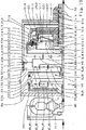
次に、図4を基に本発明による例示的第3スケルトン図を説明する。これは先に図2に基づいて説明した本発明に係る第1スケルトン図に基づいているが、但し第5、第6切換要素E、Fを有する構造群は図2に対する選択的設計構成と、変速機内部での第3、第4切換要素C、Dの選択的空間的配置とを有する。 Next, an exemplary third skeleton diagram according to the present invention will be described with reference to FIG. This is based on the first skeleton diagram according to the present invention described above with reference to FIG. 2, except that the structure group having the fifth and sixth switching elements E and F has a selective design configuration with respect to FIG. And a selective spatial arrangement of the third and fourth switching elements C, D within the transmission.
基礎となる技術の現状におけると同様に、第3切換要素Cも第4切換要素Dもブレーキとして構成され、両方とも例示的にディスクブレーキの態様である。図4から容易に明らかとなるように、いまや前置歯車組VSとは反対の主歯車組HSの側での両方のブレーキC、Dの「新規な」配置は、前置歯車組VSと主歯車組HSとの同軸配置と合せて、変速機の駆動軸ANと被動軸ABとの軸線平行な配置または角度を成した配置、つまり例えばフロント駆動装置と走行方向を横切ってまたは走行方向に沿って配置した原動機とを有する自動車用に不可欠な配置を可能とする。簡略のため図4には、主歯車組HSの出力要素を変速機被動部に結合するための必要に応じて設けられるべき平歯車段または傘歯車段は詳しくは図示されていない。図4ではやはり簡略のため詳しくは図示しないが、駆動軸ANに作用結合された変速機原動機はここでは例示的に主歯車組HSから離れた方の前置歯車組VSの側に配置されている。相応に、駆動軸ANはここでも軸線方向において変速機全体を、少なくとも全歯車組VS、HSを、事実上貫通している。その限りで、別の変速機正面に、つまり主歯車組HSの遠前置歯車組側に原動機を配置するのに、特別な設計支出は必要でない。 As in the current state of the underlying technology, both the third switching element C and the fourth switching element D are configured as brakes, both of which are exemplary disk brake modes. As is readily apparent from FIG. 4, the “new” arrangement of both brakes C, D on the side of the main gear set HS opposite to the front gear set VS is now the same as the front gear set VS and the main gear set VS. Along with the coaxial arrangement with the gear set HS, the arrangement of the transmission drive shaft AN and the driven shaft AB parallel to the axis or at an angle, that is, for example across the front drive unit and the travel direction or along the travel direction Can be placed indispensable for automobiles having a prime mover and For the sake of simplicity, FIG. 4 does not show in detail the spur gear stage or the bevel gear stage that should be provided as needed to couple the output elements of the main gear set HS to the transmission driven part. Although not shown in detail in FIG. 4 for the sake of brevity, the transmission prime mover operatively coupled to the drive shaft AN is illustratively disposed on the front gear set VS side away from the main gear set HS. Yes. Correspondingly, the drive shaft AN again penetrates through the entire transmission in the axial direction, at least through the entire gear set VS, HS. To that extent, no special design expenditure is required to place the prime mover in front of another transmission, ie on the far front gear set side of the main gear set HS.
図4で設けられる主歯車組HSは、図2と同様に「2キャリヤ‐ユニットに低減された2キャリヤ‐5軸‐遊星歯車装置」として実施されており、単一プラス‐遊星歯車組として実施される前置歯車組VSの横に同軸で、そして駆動軸ANと同軸に配置されている。主歯車組HSは互いに結合されていない4つの入力要素と1つの出力要素とを有し、互いに連結された2つの単一遊星歯車組で形成され、これら両方の単一遊星歯車組の一方は「分割太陽歯車」を有する。相応に、主歯車組HSは図2と同様に3つの太陽歯車S1−HS、S2−HS、S3−HSと、連結第1リングギヤH13−HSと、第2リングギヤH2−HSと、連結第1キャリヤST13−HSと、このキャリヤで回転可能に支承された長い遊星歯車P13−HSと、第2キャリヤST2−HSと、このキャリヤで回転可能に支承された短い遊星歯車P2−HSとを含む。主歯車組HSの入力要素がさまざまな切換要素A〜Fに結合されているとの用語法に対応して、主歯車組HSの両方の単一遊星歯車組の第2単一遊星歯車組は第2太陽歯車S2−HSと第2リングギヤH2−HSと第2キャリヤST2−HSとこのキャリヤで回転可能に支承された短い遊星歯車P2−HSとを含むが、しかし図2とは異なりいまや近前置歯車組側に配置されている。主歯車組HSの第1単一遊星歯車組は第1、第3太陽歯車S1−HS、S3−HSと連結リングギヤH13−HSと連結キャリヤST13−HSとこのキャリヤで回転可能に支承された長い遊星歯車P13−HSとを含み、図2とは異なり相応にいまや遠前置歯車組側に配置されている。短い遊星歯車P2−HSは第2リングギヤH2−HSと第2太陽歯車S2−HSとにかみ合い、長い遊星歯車P13−HSは連結リングギヤH13−HSと第1、第3太陽歯車S1−HS、S3−HSとにかみ合う。長い遊星歯車P13−HSは図2と同様に例示的に多段遊星として実施され、つまり主歯車組HSの両方の太陽歯車S1−HS、S3−HSがここでは同一の歯数を有する。空間的に見て主歯車組HSの第1太陽歯車S1−HSは軸線方向において主歯車組HSの第2、第3太陽歯車S2−HS、S3−HSの間に配置され、この第2太陽歯車S2−HSはこの第3太陽歯車S3−HSよりも前置歯車組VS近傍に配置されている。 The main gear set HS provided in FIG. 4 is implemented as “two carrier-5 shaft-planetary gear unit reduced to two carrier units” as in FIG. 2, and is implemented as a single plus-planetary gear set. Is arranged coaxially with the front gear set VS and coaxially with the drive shaft AN. The main gear set HS has four input elements and one output element which are not coupled to each other, and is formed by two single planetary gear sets connected to each other, one of both single planetary gear sets being It has a “split sun gear”. Correspondingly, the main gear set HS has three sun gears S1 - HS, S2 - HS, S3 - HS, a connected first ring gear H13 - HS, a second ring gear H2 - HS, and a connected first gear as in FIG. The carrier ST13 - HS includes a long planetary gear P13 - HS rotatably supported by the carrier, a second carrier ST2 - HS, and a short planetary gear P2 - HS rotatably supported by the carrier. Corresponding to the terminology that the input elements of the main gear set HS are coupled to the various switching elements AF, the second single planetary gear set of both single planetary gear sets of the main gear set HS is 2 includes a second sun gear S2 - HS, a second ring gear H2 - HS, a second carrier ST2 - HS, and a short planetary gear P2 - HS rotatably supported by this carrier, but is different from FIG. It is arranged on the front gear set side. The first single planetary gear set of the main gear set HS is a first and third sun gear S1 - HS, S3 - HS, a connecting ring gear H13 - HS, a connecting carrier ST13 - HS, and a long supported rotatably by this carrier. Unlike planetary gear P13 - HS, unlike FIG. 2, it is now correspondingly arranged on the far front gear set side. The short planetary gear P2 - HS meshes with the second ring gear H2 - HS and the second sun gear S2 - HS, and the long planetary gear P13 - HS connects with the connecting ring gear H13 - HS and the first and third sun gears S1 - HS, S3. - engage in and HS. Long planet gears P13 - HS is implemented as well as exemplary multi-stage planetary and 2, i.e. the main gearset both the sun gear S1 of the HS - have the same number of teeth is here HS - HS, S3. The first sun gear S1 of the main gearset HS look spatially - HS second main gearset HS in the axial direction, the third sun gear S2 - HS, S3 - is arranged between the HS, the second sun The gear S2 - HS is disposed closer to the front gear set VS than the third sun gear S3 - HS.
図2におけると同様に、第1、第2太陽歯車S1−HS、S2−HSは互いに強固に結合され、主歯車組HSの第1入力要素を形成する。この入力要素は、主歯車組HSの近前置歯車組側でクラッチB、Fの出力要素230、630と相対回転不能に結合されている。第2リングギヤH2−HSは主歯車組HSの第2入力要素を形成し、クラッチAの出力要素130と結合されている。連結キャリヤST13−HSは主歯車組HSの第3入力要素を形成し、‐ブレーキDの空間的位置に相応して‐前置歯車組VSから離れた方の主歯車組HSの側でブレーキDの出力要素430と相対回転不能に結合され、また‐クラッチEの空間的位置に相応して‐、軸線方向において第1、第3太陽歯車S1−HS、S3−HSの間を延びる半径方向挿通を介してクラッチEの出力要素530と結合されている。第3太陽歯車S3−HSは主歯車組HSの第4入力要素を形成し、‐ブレーキCの空間的位置に相応して‐前置歯車組VSから離れた方の主歯車組HSの側でブレーキCの出力要素330と相対回転可能に結合されている。連結リングギヤH13−HSと第2キャリヤST2−HSは互いに強固に結合され、変速機被動軸ABに結合された主歯車組HSの出力要素を形成する。図4による自動変速機の速度線図において主歯車組HSの第1入力要素の線と第4入力要素の線はその3つの太陽歯車S1−HS、S2−HS、S3−HSの前記部材側および運動学的連結に相応して一致する。主歯車組HSに対する両方のブレーキC、Dの運動学的連結に相応してブレーキDはブレーキCよりも主歯車組HS近傍に配置されており、ブレーキDは図2とは異なりいまやブレーキCよりも前置歯車組VS近傍にも配置されている。
As in FIG. 2, the first and second sun gears S1 - HS, S2 - HS are firmly coupled together to form the first input element of the main gear set HS. This input element is coupled to the
本発明によれば、クラッチE、Fは製造技術上簡単に予め組付可能な構造群を形成し、この構造群はいまや軸線方向において前置歯車組VSと主歯車組HSとの間の領域に配置され、軸線方向において前置歯車組VSに直接接している。この構造群はクラッチE、Fのここで両方とも例示的に外ディスク支持体として構成される入力要素520、620と、両方のクラッチE、F用に各1つのディスク束500もしくは600と、それぞれに付設されたディスク束500もしくは600を操作するための各1つのサーボ機構510もしくは610とを含む。
According to the invention, the clutches E, F form a group of structures that can be easily assembled in advance in terms of manufacturing technology, and this group of groups is now the region between the front gear set VS and the main gear set HS in the axial direction. And is in direct contact with the front gear set VS in the axial direction. This structure group includes
その際、図4に示す実施例においてクラッチFは空間的に見てクラッチEの半径方向上に配置されており、特にクラッチFのディスク束600は空間的に見てクラッチEのディスク束500の半径方向上に配置されている。クラッチEの入力要素もしくは外ディスク支持体520は幾何学的には主歯車組HSの方向に開口した鉢体の態様に構成され、そのハブは駆動軸ANと相対回転不能に結合され、図示例ではしかも駆動軸ANと共通する部材を形成する。クラッチEのサーボ機構510はクラッチEの外ディスク支持体520によって形成される円筒室の完全に内部に配置され、この外ディスク支持体520で軸線方向摺動可能に支承されている。相応に、サーボ機構510は駆動軸ANの回転数で常時回転する。サーボ機構510の回転する圧力室511の回転圧力を補償するために圧力補償室512での動的圧力補償が予定されており、この圧力室511は前記圧力補償室512よりも前置歯車組VS近傍に配置されている。
In this case, in the embodiment shown in FIG. 4, the clutch F is disposed in the radial direction of the clutch E as viewed spatially. In particular, the
クラッチFの入力要素もしくは外ディスク支持体620はやはり幾何学的には主歯車組HSの方向に開口した鉢体の態様に構成され、そのハブはその外径でクラッチEの入力要素もしくは外ディスク支持体520と相対回転不能に結合されている。つまりクラッチFの入力要素620はクラッチEの入力要素520を介して駆動軸ANと結合されている。クラッチFのサーボ機構610はクラッチFの外ディスク支持体(620)によって形成される円筒室の完全に内部に配置され、この外ディスク支持体(620)で軸線方向摺動可能に支承されている。相応に、サーボ機構610は駆動軸ANの回転数で常時回転する。サーボ機構610の回転する圧力室611の回転圧力を補償するために圧力補償室612での動的圧力補償が予定されており、この圧力室611は前記圧力補償室612よりも前置歯車組VS近傍に配置されている。
The input element or
空間的に見て、(半径方向外側)クラッチFのサーボ機構610は(半径方向内側)クラッチEのサーボ機構510の半径方向上の領域に配置されている。相応に、クラッチFの(半径方向外側)サーボ機構610の圧力室611はクラッチEの(半径方向内側)サーボ機構510の圧力室511の少なくとも概ね半径方向上に配置され、クラッチFの(半径方向外側)サーボ機構610の圧力補償室612はクラッチEの(半径方向内側)サーボ機構510の圧力補償室512の少なくとも概ね半径方向上に配置されている。クラッチEのサーボ機構510の圧力室511に至る圧媒供給および無圧充填可能な圧力補償室512に至る潤滑剤供給は一部ではクラッチEの入力要素(外ディスク支持体)520のハブの内部、一部では駆動軸ANの内部で推移する。(半径方向外側)クラッチFのサーボ機構610の圧力室611に至る圧媒供給は一部ではやはり(半径方向内側)クラッチEの入力要素(外ディスク支持体)520の内部、一部では駆動軸ANの内部で推移する。クラッチFのサーボ機構610の圧力補償室612はここで例示的にクラッチEのサーボ機構510の圧力補償室512を介して直接に潤滑剤を無圧で充填される。クラッチEを係合させるためにサーボ機構510の圧力室511に圧媒が充填され、するとこのサーボ機構は自己に付設されたクラッチEのディスク束500を軸線方向において主歯車組HSの方向に操作する。クラッチFを係合させるためにサーボ機構610の圧力室611に圧媒が充填され、するとこのサーボ機構は自己に付設されたクラッチFのディスク束600を軸線方向において主歯車組HSの方向に操作する。
When viewed spatially, the
両方のクラッチE、Fの出力要素530、630は図示実施例において両方とも内ディスク支持体として構成されている。クラッチEの内ディスク支持体530はクラッチEのディスク束500から出発して軸線方向においてクラッチEのサーボ機構510に接して半径方向内方に延設され、中心でキャリヤ軸540と相対回転不能に結合されている。このキャリヤ軸540は軸線方向において主歯車組HSの方向に、主歯車組HSの遠前置歯車組側(連結)第1キャリヤST13−HSのキャリヤ板に至るまで延設され、軸線方向において主歯車組HSの第2、第1太陽歯車S2−HS、S1−HSに中心で挿通され、軸線方向において主歯車組HSの第3、第1太陽歯車S3−HS、S1−HSの間の領域でキャリヤST13−HSの前記キャリヤ板と相対回転不能に結合されている。勿論、キャリヤST13−HSの前記キャリヤ板とキャリヤ軸540は一体に実施しておくこともできる。クラッチFの内ディスク支持体630はクラッチFのディスク束600から出発して軸線方向において一部ではクラッチEの内ディスク支持体530に接して半径方向内方に、キャリヤ軸540のすぐ上方の直径に至るまで延設され、このハブ領域においてクラッチBの出力要素230のハブと、また太陽歯車軸140を介して主歯車組HSの両方の太陽歯車S2−HS、S1−HSと相対回転不能に結合されている。つまりキャリヤ軸540はクラッチFの出力要素630のこのハブの内部に中心で、もしくはクラッチBの出力要素230のこのハブの内部、そして太陽歯車軸140の内部に中心で延びている。必要なら当業者は太陽歯車軸140を介しても両方の出力要素230、630のハブの間に結合を実現し、または両方の太陽歯車S2−HS、S1−HSも一体に実施することになる。
The
図4に示す実施例において両方のクラッチB、Aのディスク束200、100は空間的に見て軸線方向において、両方のクラッチE、Fで形成される構造群の少なくとも部分的に半径方向上の領域で少なくとも類似の直径上に並べて配置されている。クラッチBの出力要素230は軸線方向において両方のクラッチE、Fで形成される構造群を半径方向で取り囲み、この出力要素230の円筒状区域231はクラッチFの入力要素(外ディスク支持体)620の外径の少なくとも十分に半径方向上方に延設され、クラッチFに完全に被さり、この出力要素230の円板状区域232はクラッチFの出力要素(内ディスク支持体)630に対して少なくとも十分に平行に延設されている。簡略のため略示しただけの、クラッチBのディスク束200を操作するためのクラッチBのサーボ機構210は、例えば図4に示唆したように少なくとも十分に前置歯車組VSの遠主歯車組側に配置しておくことができ、駆動軸ANの回転数で常に回転することができ、自己に付設されたディスク束200を、クラッチBの係合時に軸線方向において主歯車組HSの方向に操作することができる。簡略のためやはり略示しただけの、クラッチAのディスク束100を操作するためのクラッチAのサーボ機構110は、例えば図4に示唆したように軸線方向においてクラッチBの出力要素230と主歯車組HSとの間で、主歯車組HSに向き合うディスク束100の側に配置しておくことができ、主歯車組HSのここで例示的に連結太陽歯車S1−HS、S2−HSによって形成される第1入力要素の回転数で常に回転することができ、自己に付設されたディスク束100を、クラッチAの係合時に軸線方向において前置歯車組VSの方向に操作することができる。
In the embodiment shown in FIG. 4, the disk bundles 200, 100 of both clutches B, A are axially viewed at least partially in the radial direction of the structure group formed by both clutches E, F. The regions are arranged side by side on at least similar diameters. The
次に、図5を基に本発明による例示的第4スケルトン図を説明する。これは先に図4に基づいて詳細に説明した本発明に係る第3スケルトン図に基づいているが、但し第5、第6切換要素E、Fを有する構造群は図4に対する選択的設計構成を有する。図4におけると同様に、クラッチE、Fは製造技術上簡単に予め組付可能な構造群を形成し、この構造群はクラッチE、Fのここで両方とも例示的に外ディスク支持体として構成される入力要素520、620と、両方のクラッチE、Fのサーボ機構510、610と、両方のクラッチE、Fのディスク束500、600とを含む。しかし図4とは異なり、いまやクラッチEは空間的に見てクラッチFの半径方向上に配置され、特にクラッチEのディスク束500は空間的に見てクラッチFのディスク束600の半径方向上に配置されている。
Next, an exemplary fourth skeleton diagram according to the present invention will be described with reference to FIG. This is based on the third skeleton diagram according to the present invention described in detail above with reference to FIG. 4, except that the structure group having the fifth and sixth switching elements E, F is a selective design configuration with respect to FIG. Have As in FIG. 4, the clutches E and F form a structure group that can be easily assembled in advance in terms of manufacturing technology, and this structure group is configured as an outer disk support here for both clutches E and
クラッチFの入力要素もしくは外ディスク支持体620は幾何学的には主歯車組HSの方向に開口した鉢体の態様に構成され、そのハブは駆動軸ANと相対回転不能に結合され、図示例ではしかも駆動軸ANと共通する部材を形成する。クラッチFのサーボ機構610はクラッチFの外ディスク支持体620によって形成される円筒室の完全に内部に配置され、この外ディスク支持体620で軸線方向摺動可能に支承されている。相応に、サーボ機構610は駆動軸ANの回転数で常時回転する。サーボ機構610の回転する圧力室611の回転圧力を補償するために圧力補償室612での動的圧力補償が予定されており、この圧力室611は前記圧力補償室612よりも前置歯車組VS近傍に配置されている。
The input element of the clutch F or the
クラッチEの入力要素もしくは外ディスク支持体520はやはり幾何学的には主歯車組HSの方向に開口した鉢体の態様に構成され、そのハブはその外径でクラッチFの入力要素もしくは外ディスク支持体620と相対回転不能に結合されている。つまりクラッチEの入力要素520はクラッチFの入力要素620を介して駆動軸ANと結合されている。クラッチEのサーボ機構510はクラッチEの外ディスク支持体520によって形成される円筒室の完全に内部に配置され、この外ディスク支持体520で軸線方向摺動可能に支承されている。相応に、サーボ機構510は駆動軸ANの回転数で常時回転する。サーボ機構510の回転する圧力室511の回転圧力を補償するために圧力補償室512での動的圧力補償が予定されており、この圧力室511は前記圧力補償室512よりも前置歯車組VS近傍に配置されている。
The input element or
空間的に見て、(半径方向外側)クラッチEのサーボ機構510は(半径方向内側)クラッチFのサーボ機構610の半径方向上の領域に配置されている。相応に、クラッチEの(半径方向外側)サーボ機構510の圧力室511はクラッチFの(半径方向内側)サーボ機構610の圧力室611の少なくとも概ね半径方向上に配置され、クラッチEの(半径方向外側)サーボ機構510の圧力補償室512はクラッチFの(半径方向内側)サーボ機構610の圧力補償室612の少なくとも概ね半径方向上に配置されている。クラッチFのサーボ機構610の圧力室611に至る圧媒供給および無圧充填可能な圧力補償室612に至る潤滑剤供給は一部ではクラッチFの入力要素(外ディスク支持体)620のハブの内部、一部では駆動軸ANの内部で推移する。(半径方向外側)クラッチEのサーボ機構510の圧力室511に至る圧媒供給は一部ではやはり(半径方向内側)クラッチFの入力要素(外ディスク支持体)620の内部、一部では駆動軸ANの内部で推移する。クラッチEのサーボ機構510の圧力補償室512はここで例示的にクラッチFのサーボ機構610の圧力補償室612を介して直接に潤滑剤を無圧で充填される。クラッチEを係合させるためにサーボ機構510の圧力室511に圧媒が充填され、するとこのサーボ機構は自己に付設されたクラッチEのディスク束500を軸線方向において主歯車組HSの方向に操作する。クラッチFを係合させるためにサーボ機構610の圧力室611に圧媒が充填され、するとこのサーボ機構は自己に付設されたクラッチFのディスク束600を軸線方向において主歯車組HSの方向に操作する。
From a spatial point of view, the
クラッチB、E、Fの出力要素230、530、630と主歯車組HSの3つの太陽歯車S1−HS、S2−HS、S3−HSとの間の運動学的連結に相応して、前記第2太陽歯車S2−HSは図8と同様に近前置歯車組側に配置され、第1太陽歯車S1−HSは軸線方向において第2、第3太陽歯車S2−HS、S3−HSの間に配置されている。図8とは異なり、主歯車組HSの互いに固定結合された太陽歯車S1−HS、S2−HSによって結合される第1入力要素がなおクラッチBの出力要素230と結合されているだけであるのに対して、主歯車組HSの第3太陽歯車S3−HSによって形成される第4入力要素はいまやブレーキCの出力要素330ともクラッチFの出力要素630とも結合されている。ここでは短い太陽歯車軸140によって互いに結合された太陽歯車S2−HS、S3−HSは、当然、必要なら一体に実施しておくこともできる。
Clutch B, E, 3 single sun gear S1 of the main gearset HS and the output element 230,530,630 of F - HS, S2 - HS, S3 - Corresponding to kinematic connection between the HS, the first The two sun gears S2 - HS are arranged on the near front gear set side as in FIG. 8, and the first sun gear S1 - HS is between the second and third sun gears S2 - HS, S3 - HS in the axial direction. Has been placed. Unlike FIG. 8, the main gear set sun gear fixedly coupled to one another in the HS S1 - HS, S2 - it's only the first input element coupled is still coupled to the
両方のクラッチE、Fの出力要素530、630は図5に示す実施例において両方とも内ディスク支持体として構成されている。クラッチFの内ディスク支持体630はクラッチFのディスク束600から出発して軸線方向においてクラッチFのサーボ機構610に接して半径方向内方に延設され、中心で第3太陽歯車軸640と相対回転不能に結合されている。この第3太陽歯車軸640は軸線方向において主歯車組HSの方向に、少なくともその遠前置歯車組側第3太陽歯車S3−HSに至るまで延設され、軸線方向において主歯車組HSの少なくとも(近前置歯車組側)第2太陽歯車S2−HSと(空間的に見て中央の)第1太陽歯車S1−HSとに中心で挿通され、この第3太陽歯車S3−HSと相対回転不能に結合されている。基本的に第3太陽歯車軸640はこの第3太陽歯車S3−HSにも中心で挿通される。というのも、ブレーキCの出力要素330は主歯車組HSの遠前置歯車組側でこの第3太陽歯車S3−HSと、またはまさにこの第3太陽歯車軸640と相対回転不能に結合されている。クラッチEの内ディスク支持体530はクラッチEのディスク束500から出発して一部ではクラッチFの内ディスク支持体630に接して半径方向内方に、第3太陽歯車軸640のすぐ上方の直径に至るまで延設され、このハブ領域においてキャリヤ軸540と相対回転不能に結合されている。このキャリヤ軸540はそれ自体第3太陽歯車軸640を半径方向で取り囲み、軸線方向において主歯車組HSの方向に、主歯車組HSの遠前置歯車組側連結キャリヤST13−HSのキャリヤ板に至るまで延設され、同様に軸線方向において主歯車組HSの第2、第1太陽歯車S2−HS、S1−HSに挿通され、軸線方向において主歯車組HSの第1、第3太陽歯車S1−HS、S3−HSの間の領域で連結キャリヤST13−HSの前記キャリヤ板と相対回転不能に結合されている。勿論、キャリヤST13−HSの前記キャリヤ板とキャリヤ軸540は一体に実施しておくこともできる。
The
図5に示す実施例において両方のクラッチB、Aのディスク束200、100は空間的に見て軸線方向において、両方のクラッチE、Fで形成される構造群の少なくとも部分的に半径方向上の領域で少なくとも類似の直径上に並べて配置されている。クラッチBの出力要素230は軸線方向において両方のクラッチE、Fで形成される構造群を半径方向で取り囲み、この出力要素230の円筒状区域231はクラッチEの入力要素(外ディスク支持体)520の外径の少なくとも十分に半径方向上方に延設され、クラッチEに完全に被さり、この出力要素230の円板状区域232はクラッチEの出力要素(内ディスク支持体)530に対して少なくとも十分に平行に、半径方向内方に、キャリヤ軸540のすぐ上方の直径に至るまで延設されている。クラッチBの出力要素230はそのハブ領域で主歯車組HSの近前置歯車組側第2太陽歯車S2−HSと、また太陽歯車軸140を介して主歯車組HSの(空間的に見て中央の)第1太陽歯車S1−HSとも、相対回転不能に結合されている。つまりキャリヤ軸540はクラッチEの出力要素230のこのハブの内部で中心を、そして太陽歯車軸140の内部で中心を延びている。
In the embodiment shown in FIG. 5, the disk bundles 200, 100 of both clutches B, A are axially viewed at least partially in the radial direction of the group of structures formed by both clutches E, F. The regions are arranged side by side on at least similar diameters. The
その他の点で、図5に示す本発明に係る第4部材配置は既に図4に示す本発明に係る第3部材配置に実質一致している。 In other respects, the fourth member arrangement according to the invention shown in FIG. 5 is substantially identical to the third member arrangement according to the invention shown in FIG.
次に、図6を基に本発明による例示的第5スケルトン図を以下で説明する。これはやはり図4に基づいて説明した本発明に係る第3スケルトン図に基づいているが、但し変速機内部での第5、第6切換要素E、Fを有する構造群の図4に対する選択的空間的配置を有する。依然として、両方のクラッチE、Fは製造技術上簡単に予め組付可能な構造群を形成し、この構造群は両方のクラッチE、Fに共通するディスク支持体ZYLEFと、両方のクラッチE、Fのサーボ機構510、610と、両方のクラッチE、Fのディスク束500、600とを含む。図4とは異なり、クラッチE、Fからなるこの構造群はいまや前置歯車組VSから離れた方の主歯車組HSの側に配置されている。分割太陽歯車(つまり両方の太陽歯車S1−HS、S2−HS)を有する主歯車組HSの遊星歯車組はクラッチE、Fからなる構造群に向き合い、主歯車組HSの太陽歯車S3−HSは軸線方向において前記構造群に接している。相応に、主歯車組HSの他方の単一遊星歯車組はその太陽歯車S2−HSが前置歯車組VSに向き合っている。
Next, an exemplary fifth skeleton diagram according to the present invention will be described below with reference to FIG. This is also based on the third skeleton diagram according to the present invention described with reference to FIG. 4, except that the structure group having the fifth and sixth switching elements E, F inside the transmission is selective to FIG. Has a spatial arrangement. Still, both clutches E and F form a structure group that can be easily assembled in advance in terms of manufacturing technology. This structure group includes a disk support ZYLEF common to both clutches E and F, and both clutches E and
クラッチE、Fに共通するディスク支持体ZYLEFは両方のクラッチE、F用にそれらの入力要素を形成し、相応に駆動軸ANと相対回転不能に結合されている。クラッチE用にディスク支持体ZYLEFはクラッチEのディスク束500の外ディスクを受容するための外ディスク支持体として構成され、クラッチF用にはクラッチFのディスク束600の内ディスクを受容するための内ディスク支持体として構成されている。クラッチFのディスク束600は空間的に見てクラッチEのディスク束500の半径方向上の領域に配置されている。幾何学的には、前記ディスク支持体ZYLEFは実質的に主歯車組HSの方向に開口した鉢体の態様に構成され、クラッチEのディスク束500の外ディスクをその内径に配置した多段円筒状区域521と、前記円筒状区域521の遠前置歯車組側末端から出発して半径方向内方に延設された少なくとも十分に円板状の区域(鉢底)522と、前記鉢底(522)の内径から軸線方向において主歯車組HSの方向に延設されかつその近主歯車組側末端で駆動軸ANに結合された、クラッチEに付設されるべき第1ハブ区域523と、クラッチFに付設されるべき第2ハブ区域623とを有する。この第2ハブ区域は前記鉢底(522)の内径から出発して軸線方向において主歯車組HSとは逆方向に延設され、その遠主歯車組側末端は変速機ケースGGに相対回転不能に結合されたケース蓋GDで回転可能に支承されている。符号621は円筒状区域521の外径であり、この区域がクラッチFにも付設されることを指摘するものである。つまりこの外径にはクラッチFのディスク束600の内ディスクを受容するための連行断面が設けられている。
A disk support ZYLEF common to the clutches E, F forms their input elements for both clutches E, F and is correspondingly connected to the drive shaft AN in a relatively non-rotatable manner. The disk support ZYLEF for the clutch E is configured as an outer disk support for receiving the outer disk of the
クラッチEのディスク束500を操作するためのサーボ機構510は圧力室511と圧力補償室512とピストン514と戻し要素513と堰円板515とを含み、ディスク支持体ZYLEFの第1ハブ区域523の半径方向上方、ディスク支持体ZYLEF、特にその円筒状区域521によって形成される円筒室の完全に内部に配置されている。ピストン514はこのディスク支持体ZYLEFで軸線方向摺動可能に支承されている。相応にサーボ機構510は駆動軸ANの回転数で常時回転する。サーボ機構510の回転する圧力室511の回転圧力を補償するために、潤滑剤を無圧充填可能な圧力補償室512での動的圧力補償が予定されており、この圧力補償室512は前記圧力室511よりも主歯車組HS近傍に配置されている。圧力室511はディスク支持体ZYLEFの外被面とピストン514とによって形成される。圧力補償室512はピストン514と堰円板515とによって形成され、この堰円板は軸線方向においてディスク支持体ZYLEFのハブ区域523に固定され、ピストン515に対して軸線方向摺動可能に潤滑剤密に密封されている。ピストン514は、ここで例示的に皿ばねとして構成される戻し要素513を介して軸線方向においてディスク支持体ZYLEFのハブ区域523の方向に付勢されている。クラッチEを係合させるために圧力室511に圧媒が付加されるとピストン514は軸線方向において主歯車組HSの方向に移動し、自己に付設されたディスク束500を戻し要素513のばね力に抗して操作する。
The
空間的に見てクラッチEのサーボ機構510はクラッチFのサーボ機構610よりも前置歯車組VS、主歯車組HS近傍に配置されている。このサーボ機構610は空間的に見て少なくとも十分にディスク支持体ZYLEFの第2ハブ区域623の半径方向上の領域に配置され、ディスク支持体ZYLEFでも軸線方向摺動可能に支承されている。相応にサーボ機構610も駆動軸ANの回転数で常時回転する。クラッチFのサーボ機構610は圧力室611と圧力補償室612と一部で蛇行構成されたピストン614と戻し要素613と円筒状堰円板615と鉢状支持円板618とを含む。サーボ機構610の回転する圧力室611の回転圧力を補償するために、圧力補償室612での動的圧力補償が予定されている。このため円筒状堰円板615は限定的直径で、ディスク支持体ZYLEFの円板状区域522に潤滑剤密に固着され(図示例では溶接され)、軸線方向で隣接するピストン614に向かって軸線方向摺動可能に潤滑剤密に密封され、堰円板615の半径方向下方にあるディスク支持体ZYLEFの外被面621、および堰円板615の半径方向下方にあるピストン614の外被面と一緒に、前記圧力補償室612を形成する。つまりクラッチFのサーボ機構610の圧力補償室612と、クラッチEのサーボ機構510の圧力室511は互いに直接隣接して配置され、クラッチE、Fに共通するディスク支持体ZYLEFの外被面のみによって相互に分離されている。主歯車組HSもしくは圧力室511から離れた方の圧力補償室612の側にサーボ機構610の圧力室611が配置されている。この圧力室611はピストン615と支持円板618とハブ623の軸線方向区域とによって形成される。このため支持円板618は圧媒密にハブ623に固着されている。ハブ623の圧力室612を形成する区域の半径方向上方でこの鉢状支持円板618の円筒状区域は軸線方向において主歯車組HSの方向(もしくは軸線方向において圧力室511の方向)に延設され、ピストン614の対応する区域に向かって圧媒密に軸線方向摺動可能に密封されている。そのさらなる幾何学的推移においてピストン614は少なくとも十分に支持円板618の外輪郭とディスク支持体ZYLEFの上側領域とに沿って半径方向外方に、軸線方向において主歯車組HSの方向に、クラッチFの自己に付設されたディスク束600の遠主歯車組側に至るまで延設されている。ピストン614を軸線方向で付勢する戻し要素613はここで例示的に、軸線方向においてディスク支持体の円板状区域621とピストン614との間に配置される渦巻ばね束として構成されている。クラッチFを係合させるために圧力室611に圧媒が付加されるとピストン614は軸線方向において主歯車組HSの方向に移動し、自己に付設されたディスク束600を戻し要素613のばね力に抗して操作する。
The
ディスク支持体ZYLEFが変速機ケース固定ケース蓋GDで支承されているので、両方のクラッチE、Fへの圧媒および潤滑剤供給は相応する通路もしくは穴を介して設計上比較的簡単に得られる。これらの通路もしくは穴は一部では前記変速機ケース固定ケース蓋GDの内部、一部ではディスク支持体ZYLEFのハブの内部を延びている。符号516はクラッチEのサーボ機構510の圧力室511に至る圧媒供給部、符号517はクラッチEのサーボ機構510の圧力補償室512に至る潤滑剤供給部、符号616はクラッチFのサーボ機構610の圧力室611に至る圧媒供給部、符号617はクラッチFのサーボ機構610の圧力補償室612に至る潤滑剤供給部である。
Since the disk support ZYLEF is supported by the transmission case fixed case lid GD, the supply of the pressure medium and the lubricant to both clutches E and F can be obtained relatively easily by design through corresponding passages or holes. . These passages or holes extend partly inside the transmission case fixing case lid GD and partly inside the hub of the disk support ZYLEF.
つまり両方のクラッチE、Fによって形成される構造群が両方のクラッチE、Fに共通するディスク支持体ZYLEFと両方のクラッチE、Fのサーボ機構510、610およびディスク束500、600とを有する図6に示す部材側構成は、両方のクラッチE、Fへの圧媒供給および潤滑剤供給の細部に至るまで、この構造群が両方のクラッチE、Fを有する図2に示した部材側構成と実質一致している。
That is, a structure group formed by both clutches E and F includes a disk support ZYLEF common to both clutches E and F,
クラッチEの出力要素530は内ディスク支持体として構成され、クラッチEのディスク束500から出発して軸線方向においてクラッチEのサーボ機構510に接して半径方向内方に、駆動軸ANのすぐ上方に至るまで延設され、そのハブ領域においてキャリヤ軸540と相対回転不能に結合されている。このキャリヤ軸540は軸線方向において前置歯車組VSの方向に、主歯車組HSの(遠前置歯車組側)第3太陽歯車S3−HSと(空間的に中央の)第1太陽歯車S1−HSとの間の領域に至るまで延設され、軸線方向において主歯車組HSの第3太陽歯車S3−HSに中心で挿通される。軸線方向において太陽歯車S3−HS、S1−HSの間の前記領域においてキャリヤ軸540は主歯車組HSの遠前置歯車組側連結キャリヤST13−HSのキャリヤ板と相対回転不能に結合されており、キャリヤST13−HSのこの前記キャリヤ板は近主歯車組側に配置されるブレーキDの出力要素430とも相対回転不能に結合されている。
The
クラッチFの出力要素630は外ディスク支持体として構成され、クラッチFのディスク束600から出発して軸線方向においてクラッチEの出力要素(もしくは内ディスク支持体)530に接してキャリヤ軸540のすぐ上方に至るまで半径方向内方に延設され、そのハブ領域で主歯車組HSの(遠前置歯車組側)第3太陽歯車S3−HSと相対回転不能に結合されている。やはり主歯車組HSの第3太陽歯車S3−HSに運動学的に連結されたブレーキCの出力要素330はここで例示的にクラッチFの外ディスク支持体(630)の外径領域でこの外ディスク支持体(630)と相対回転不能に結合されており、ブレーキCは例示的に軸線方向においてブレーキDの直接横でその遠主歯車組側に配置されている。
The
その他の点で、図6に示す部材配置は既に図4に示した配置に実質一致している。 In other respects, the member arrangement shown in FIG. 6 is substantially identical to the arrangement shown in FIG.
勿論、図6を基に説明した部材配置は別の主歯車組形式と組合せることもできる。そのための相応する1例を次に図7に示す本発明に係る第6スケルトン図を基に説明する。この場合主歯車組HSは2キャリヤ‐遊星歯車装置に低減された3キャリヤ‐4軸‐遊星歯車装置であり、いまや3つの太陽歯車S1−HS、S2−HS、S3−HSと3つのリングギヤH1−HS、H2−HS、H3−HSと連結キャリヤST13−HSとこのキャリヤで回転可能に支承された遊星歯車P1−HS、P3−HSと単一キャリヤST2−HSとこのキャリヤで回転可能に支承された遊星歯車P2−HSとを含む。太陽歯車S1−HSと、リングギヤH1−HSと、この太陽歯車S1−HSおよびこのリングギヤH1−HSにかみ合う遊星歯車P1−HSは、主歯車組HSの3つの単一遊星歯車組の第1単一遊星歯車組に付設されている。太陽歯車S2−HSと、リングギヤH2−HSと、この太陽歯車S2−HSおよびこのリングギヤH2−HSにかみ合う遊星歯車P2−HSは、主歯車組HSの3つの単一遊星歯車組の第2単一遊星歯車組に付設されている。最後に太陽歯車S3−HSと、リングギヤH3−HSと、この太陽歯車S3−HSおよびこのリングギヤH3−HSにかみ合う遊星歯車P3−HSは、主歯車組HSの3つの単一遊星歯車組の第3単一遊星歯車組に付設されている。空間的に見て主歯車組HSの3つの単一遊星歯車組の前記第1単一遊星歯車組はやはり軸線方向において主歯車組HSの3つの単一遊星歯車組の近前置歯車組側第2単一遊星歯車組と主歯車組HSの3つの単一遊星歯車組の遠前置歯車組側第3単一遊星歯車組との間に配置されている。両方の太陽歯車S2−HS、S1−HSは互いに強固に結合されている。主歯車組HSの他の運動学的連結として(単一)キャリヤST2−HSと両方のリングギヤH1−HS、H3−HSとの間に固定結合が設けられている。 Of course, the member arrangement described with reference to FIG. 6 can be combined with another main gear set type. A corresponding example for this will be described with reference to the sixth skeleton diagram of the present invention shown in FIG. In this case, the main gear set HS is a three-carrier four-axis-planetary gear unit reduced to a two-carrier-planetary gear unit, and now three sun gears S1 - HS, S2 - HS, S3 - HS and three ring gears H1. - HS, H2 - HS, H3 - HS consolidated carrier ST13 - HS and rotatably supported by the carrier has been planetary gear P1 - HS, P3 - HS and a single carrier ST2 - HS and rotatably supported by the carrier Planetary gear P2 - HS. Sun gear S1 - HS and the ring gear H1 - HS and, the sun gear S1 - HS and the ring gear H1 - planetary gears meshing with the HS P1 - HS has three single planetary gear set of the first single main gearset HS It is attached to one planetary gear set. Sun gear S2 - HS and the ring gear H2 - HS and, the sun gear S2 - HS and the ring gear H2 - planetary gear P2 meshing with HS - HS has three single planetary gear set of the second single main gearset HS It is attached to one planetary gear set. Finally the sun gear S3 - HS and the ring gear H3 - HS and, the sun gear S3 - planetary gear P3 meshing with HS - - HS and the ring gear H3 HS is first of three single planetary gear set of the main gearset HS It is attached to 3 single planetary gear sets. When viewed spatially, the first single planetary gear set of the three single planetary gear sets of the main gear set HS is also located in the axial direction in the near front gear set side of the three single planetary gear sets of the main gear set HS. The second single planetary gear set and the third single planetary gear set on the far front gear set side of the three single planetary gear sets of the main gear set HS are arranged. Both sun gears S2 - HS and S1 - HS are firmly connected to each other. As another kinematic connection of the main gear set HS, a fixed connection is provided between the (single) carrier ST2 - HS and both ring gears H1 - HS, H3 - HS.
図7に示す主歯車組HSの変更態様において例えば、主歯車組HSの連結キャリヤST13−HSで回転可能に支承される両方の遊星歯車P1−HS、P3−HSを1つの多段遊星歯車へとまとめることを予定することもでき、その場合、図7において主歯車組HSの被動軸ABに結合された両方のリングギヤH1−HS、H3−HSの一方はこれにより省くことができる。 For example, in variations of the main gearset HS shown in Figure 7, the main gearset HS connected carrier ST13 of - to HS one multistage planetary gears - both of the planetary gear which is rotatably supported by the HS P1 - HS, P3 In this case, one of the two ring gears H1 - HS, H3 - HS coupled to the driven shaft AB of the main gear set HS in FIG. 7 can be omitted.
次に図8に基づいて本発明による例示的第7スケルトン図を以下で説明する。これは先に図6で述べた本発明に係る第5スケルトン図に基づいており、それに対する変更は実質的に両方のクラッチE、Fによって形成される構造群の設計構成にのみ関係している。引き続きこの構造群は前置歯車組VSから離れた方の主歯車組HSの側に配置され、両方のクラッチE、Fに共通するディスク支持体ZYLEFと、両方のクラッチE、Fのサーボ機構510、610と、両方のクラッチE、Fのディスク束500、600とを含む。このディスク支持体ZYLEFは両方のクラッチE、F用にその入力要素を形成し、相応に駆動軸ANと相対回転不能に結合されている。
An exemplary seventh skeleton diagram according to the present invention will now be described below with reference to FIG. This is based on the fifth skeleton diagram according to the present invention described above with reference to FIG. 6, and the change thereto is substantially only related to the design configuration of the structure group formed by both clutches E, F. . This structure group continues to be disposed on the side of the main gear set HS that is remote from the front gear set VS, and the disk support ZYLEF common to both clutches E and F, and the
図8で明らかとなるように、クラッチFのディスク束600はいまや空間的に見てクラッチEのディスク束500の半径方向下に配置されている。相応に、ディスク支持体ZYLEFはクラッチF用にこのクラッチFの(いまや半径方向内側の)ディスク束600の外歯ディスクを受容するための外ディスク支持体として構成され、クラッチE用にはクラッチEの(いまや半径方向外側の)ディスク束500の内歯ディスクを受容するための内ディスク支持体として構成されている。相応に両方のクラッチE、Fのサーボ機構510、610の空間的位置も図6に対して入れ替わっており、クラッチFのサーボ機構610はいまやクラッチEのサーボ機構510よりも主歯車組HS近傍に配置されている。その限りで、先に図6に基づいて詳細に説明したこれらサーボ機構510、610の構成は意味に即して容易に転用可能であり、それゆえにここでそれらを再度言葉で説明することは省くことができる。誤解を避けるためにここでは、異なる新しい符号を特に付記しておくだけとする。図8において符号623はディスク支持体ZYLEFの‐いまやクラッチFに付設されるべき‐近主歯車組側ハブ区域、符号523はディスク支持体ZYLEFの‐いまやクラッチEに付設されるべき‐遠主歯車組側ハブ区域である。クラッチEのサーボ機構510の圧力室511を形成するために支持円板518が設けられており、この支持円板は遠主歯車組側ハブ区域523に圧媒密に固着され、このサーボ機構510の一部で蛇行構成されたピストン514に対して圧媒密に軸線方向摺動可能である。図6とは異なり、クラッチFのサーボ機構610の圧力室611とクラッチEのサーボ機構510の圧力補償室512はいまや互いに直接隣接して配置され、ディスク支持体ZYLEFの外被面のみによって相互に分離されている。
As can be seen in FIG. 8, the
図8でさらに明らかとなるように、クラッチFの出力要素630は図6とは異なりいまや内ディスク支持体として構成され、クラッチE、Fで構成される構造群の半径方向内側ディスク束600から出発して軸線方向においてクラッチFのサーボ機構610に接して半径方向内方に、駆動軸ANのすぐ上方にまで延設され、そのハブ領域において第3太陽歯車軸640と相対回転不能に結合されている。この第3太陽歯車軸640は半径方向で駆動軸ANに取り囲み、軸線方向において前置歯車組VSの方向に延設され、軸線方向において主歯車組HSに中心で完全に挿通されている。この第3太陽歯車軸640は一方で主歯車組HSの(空間的に中央の)第1太陽歯車S1−HSと(近前置歯車組側)第2太陽歯車S2−HSとにも、他方で(空間的に見て軸線方向において前置歯車組VSと主歯車組HSとの間の領域で)クラッチBの出力要素230とも、相対回転不能に結合されている。ブレーキCの出力要素330は主歯車組HSの(遠前置歯車組側)第3太陽歯車S3−HSと相対回転不能に直接結合され、図示例では軸線方向において一部では主歯車組HSに直接接している。
As will become more apparent in FIG. 8, the
図6とは異なり、図8ではクラッチEの出力要素530がいまや外ディスク支持体として構成されている。クラッチE、Fで構成される構造群の半径方向外側ディスク束500から出発して、クラッチEのこの外ディスク支持体(530)は軸線方向においてクラッチFの出力要素(内ディスク支持体)630とブレーキCの出力要素330との間で一部では少なくとも十分に平行に、半径方向内方に、第3太陽歯車軸640のすぐ上方の直径に至るまで延設されている。そのハブ領域においてクラッチEの内ディスク支持体(530)はやはり、第3太陽歯軸640を半径方向で取り囲むキャリヤ軸540と相対回転不能に結合されている。図6と同様に、キャリヤ軸540は軸線方向において主歯車組HSの(遠前置歯車組側)第3太陽歯車S3−HSに挿通され、軸線方向において太陽歯車S3−HS、S1−HSの間の領域で主歯車組HSの(遠前置歯車組側)連結キャリヤST13−HSのキャリヤ板と相対回転不能に結合されている。
Unlike FIG. 6, in FIG. 8, the
その他の点で、図8に示す部材配置は既に図6に示した配置に一致している。 In other respects, the member arrangement shown in FIG. 8 already matches the arrangement shown in FIG.
勿論、図8を基に説明した部材配置も、別の主歯車組形式と組合せることもできる。相応する例が図9に本発明に係る第8スケルトン図として示してある。この場合主歯車組HSは2キャリヤ‐遊星歯車装置に低減された3キャリヤ‐4軸‐遊星歯車装置であり、図7で説明した主歯車組HSと同一に構成されており、それゆえにここでそれを再度詳しく説明することは省くことができる。 Of course, the member arrangement described with reference to FIG. 8 can also be combined with another main gear set type. A corresponding example is shown in FIG. 9 as the eighth skeleton diagram according to the invention. In this case, the main gear set HS is a three-carrier, four-shaft-planetary gear set reduced to a two-carrier-planetary gear set, and is configured identically to the main gear set HS described in FIG. It can be omitted to explain it in detail again.
次に図10に基づいて本発明による例示的第9スケルトン図を説明する。これは先に図8で述べた本発明に係る第6スケルトン図に基づいているが、但し図8に対する選択的主歯車組HSと、第5、第6切換要素E、Fを有する構造群の図8に対する選択的設計構成とを有する。 Next, an exemplary ninth skeleton diagram according to the present invention will be described with reference to FIG. This is based on the sixth skeleton diagram according to the present invention described above with reference to FIG. 8, except that the structure group having the selective main gear set HS and the fifth and sixth switching elements E and F with respect to FIG. And a selective design configuration for FIG.
図10で明らかとなるように、「新規な」主歯車組HSはいまや、3つの入力要素と1つの出力要素とを有する2キャリヤ‐4軸‐遊星歯車装置として構成され、互いに連結された2つの単一遊星歯車組を含み、そのうち第1単一遊星歯車組は単一遊星構造様式に実施され、第2単一遊星歯車組は二重遊星構造様式に実施されている。主歯車組HSの第2単一遊星歯車組は前置歯車組VSに向き合い、太陽歯車S2−HSとリングギヤH2−HSと連結キャリヤST2−HSとこのキャリヤで回転可能に支承された内側および外側遊星歯車PLi−HS、PLa−HSとを含む。内側遊星歯車PLi−HSは太陽歯車S2−HSと外側遊星歯車PLa−HSとにかみ合い、外側遊星歯車PLa−HSは内側遊星歯車PLi−HSと前記リングギヤH2−HSとにかみ合う。主歯車組HSの第1単一遊星歯車組は主歯車組HSの第2単一遊星歯車組の前置歯車組VSから離れた方の側に配置され、太陽歯車S1−HSとリングギヤH1−HSとキャリヤST1−HSとこのキャリヤで回転可能に支承された遊星歯車PL−HSとを含む。遊星歯車PL−HSは太陽歯車S1−HSとリングギヤH1−HSとにかみ合う。 As can be seen in FIG. 10, the “new” main gear set HS is now configured as a two-carrier four-axis-planetary gear arrangement with three input elements and one output element, connected to each other. It includes two single planetary gear sets, of which the first single planetary gear set is implemented in a single planetary structure mode and the second single planetary gear set is implemented in a double planetary structure mode. The second single planetary gear set of the main gear set HS faces the front gear set VS, the sun gear S2 - HS, the ring gear H2 - HS, the coupling carrier ST2 - HS, and the inner and outer sides rotatably supported by this carrier. Including planetary gears PLi - HS and PLa - HS. The inner planetary gear PLi - HS meshes with the sun gear S2 - HS and the outer planetary gear PLa - HS, and the outer planetary gear PLa - HS meshes with the inner planetary gear PLi - HS and the ring gear H2 - HS. The first single planetary gear set of the main gearset HS is disposed on a second side facing away from the single planetary gear set before置歯car sets VS of the main gearset HS, sun gear S1 - HS and the ring gear H1 - HS, a carrier ST1 - HS, and a planetary gear PL - HS rotatably supported by the carrier. The planetary gear PL - HS meshes with the sun gear S1 - HS and the ring gear H1 - HS.
主歯車組HSの第1太陽歯車S1−HSと連結第2キャリヤST2−HSは互いに相対回転不能に結合され、主歯車組HSの第1入力要素を形成する。この入力要素は両方のクラッチB、Fの出力要素230、630とブレーキCの出力要素330とに結合されている。クラッチB、Fの出力要素230、630が第1太陽歯車軸240を介して太陽歯車S1−HSと相対回転不能に結合されているのに対して、ブレーキCの出力要素330はキャリヤST2−HSの前置歯車組側キャリヤ板と相対回転不能に結合されている。クラッチBの入力要素220はそれ自体前置歯車組VSのリングギヤHO−VSと結合されている。クラッチFの入力要素620はそれ自体駆動軸ANと結合されている。ブレーキCの入力要素320はそれ自体変速機ケースGGと結合され、もしくは変速機ケースGGに一体化されている。
The first sun gear S1 - HS and the coupled second carrier ST2 - HS of the main gear set HS are coupled to each other such that they cannot rotate relative to each other, and form a first input element of the main gear set HS. This input element is coupled to the
主歯車組HSの近前置歯車組側第2太陽歯車S2−HSは主歯車組HSの第2入力要素を形成し、クラッチAの出力要素130と結合されている。クラッチAの入力要素120はそれ自体前置歯車組VSのリングギヤHO−VSと結合されている。
The near front gear set side second sun gear S2 - HS of the main gear set HS forms a second input element of the main gear set HS and is coupled to the
主歯車組HSの第1キャリヤST1−HSと第2リングギヤH2−HSは互いに結合され、主歯車組HSの第3入力要素を形成する。この入力要素はそれ自体クラッチEの出力要素530とブレーキDの出力要素430とに結合されている。クラッチEの出力要素530がキャリヤST1−HSの遠前置歯車組側キャリヤ板と相対回転不能に結合されているのに対して、ブレーキDの出力要素430はリングギヤH2−HSもしくはキャリヤST1−HSの近前置歯車組側キャリヤ板と相対回転不能に結合されている。クラッチEの入力要素520はそれ自体前駆動軸ANと結合されている。ブレーキDの入力要素420はそれ自体変速機ケースGGと結合され、もしくは変速機ケースGGに一体化されている。
The first carrier ST1 - HS and the second ring gear H2 - HS of the main gear set HS are coupled together to form a third input element of the main gear set HS. This input element is itself coupled to the
主歯車組HSの遠前置歯車組側第1リングギヤH1−HSは主歯車組HSの出力要素を形成し、変速機の被動軸ABと結合されている。図10に示す実施例において被動軸ABは駆動軸ANと同軸に延びている。しかし当業者は、必要なら、図10の図示から離れて被動軸ABを駆動軸ANと軸線平行にまたは角度を成して配置することになる。 The far front gear set side first ring gear H1 - HS of the main gear set HS forms an output element of the main gear set HS and is coupled to the driven shaft AB of the transmission. In the embodiment shown in FIG. 10, the driven shaft AB extends coaxially with the drive shaft AN. However, those skilled in the art will place the driven shaft AB parallel to or at an angle to the drive shaft AN, if desired, away from the illustration of FIG.
図10による本発明に係るこの第9スケルトン図の切換ロジックは図1Bに示した前文に係る変速機の切換ロジックに一致している。 The switching logic of this ninth skeleton diagram according to the invention according to FIG. 10 corresponds to the switching logic of the transmission according to the preamble shown in FIG. 1B.
変速機ケースGG内部での6つの切換要素A〜Fの空間的配置は主歯車組HSの個々の構成要素に対するそれらの前記運動学的結合にそれぞれ対応する。図10で明らかとなるように、ブレーキCはそのディスク束300およびそのサーボ機構310が変速機ケースGGの内径領域に、空間域に見て軸線方向において十分に主歯車組HSの横でその近前置歯車組側に、しかし一部では主歯車組HSの近前置歯車組側第2リングギヤH2−HSの半径方向上にも、配置されている。必要なら当業者はブレーキCを、図10の図示から離れて例えば変速機ケース固定ケース壁GW近傍の領域で前置歯車組VSの遠主歯車組側にも配置することになる。図10でさらに明らかとなるように、ブレーキDはそのディスク束400およびそのサーボ機構410が変速機ケースGGの内径領域に、しかし空間域に見て主歯車組HSの半径方向上の領域に、そして主歯車組HSの近前置歯車組側第2リングギヤH2−HSの概ね半径方向上に配置されている。
The spatial arrangement of the six switching elements A to F within the transmission case GG respectively corresponds to their kinematic coupling to the individual components of the main gear set HS. As will be apparent from FIG. 10, the brake C has its
図10でさらに明らかとなるように、クラッチAは軸線方向において主歯車組HSにその近前置歯車組側で直接続いている。主歯車組HSの第2太陽歯車S2−HSに結合されたクラッチAの出力要素130は円筒状外ディスク支持体として構成され、幾何学的には前置歯車組VSの方向に開口した鉢体の形状であり、クラッチAのディスク束100とクラッチAのこのディスク束100を操作するためのサーボ機構110がこの鉢体の内部に配置されている。相応に、クラッチAのサーボ機構110は主歯車組HSの第2太陽歯車S2−HSの回転数で常に回転する。クラッチAの相応に内ディスク支持体として構成される入力要素120はクラッチBの入力要素220を介して前置歯車組VSのリングギヤHO−VSと相対回転不能に結合されている。クラッチBはそれ自体一部では前置歯車組VSの遠主歯車組側に、一部では前置歯車組VSの半径方向上に配置されている。クラッチBのディスク束200は少なくとも一部では前置歯車組VSのリングギヤHO−VSの半径方向上に配置されている。クラッチBのこのディスク束200を操作するためのサーボ機構210は少なくとも十分に、主歯車組HSとは反対の前置歯車組VSの側に配置されている。リングギヤHO−VSに結合されるクラッチBの入力要素220は円筒状外ディスク支持体として構成され、幾何学的には主歯車組HSの方向に開口した鉢体の形状であり、クラッチBのディスク束200とサーボ機構210がこの鉢体の内部に配置されている。クラッチBの相応に内ディスク支持体として構成される出力要素230は主歯車組HSに向き合う前置歯車組VSの側でこの前置歯車組VSに直接接し、そのハブ領域において、主歯車組HSの第1太陽歯車S1−HS(および第2キャリヤST2−HSの遠前置歯車組側キャリヤ板)に運動学的に結合するために、既に触れた第1太陽歯車軸240と相対回転不能に結合されている。第1太陽歯車軸240はそれ自体駆動軸ANを取り囲み、その軸線方向推移においてクラッチBの出力要素230もしくは内ディスク支持体のハブから出発してまず、クラッチAの出力要素130もしくは外ディスク支持体によって形成されるクラッチAのクラッチ室に中心で完全に挿通され、引き続き主歯車組HSの近前置歯車組側第2太陽歯車S2−HSに中心で完全に挿通される。
As will become more apparent in FIG. 10, the clutch A directly follows the main gear set HS on its near front gear set side in the axial direction. The second sun gear S2 of the main gearset HS -
図10でさらに明らかとなるように、両方のクラッチE、Fは製造技術上好ましいことに予め組付可能な構造群を形成し、この構造群は両方のクラッチE、Fに共通するディスク支持体ZYLEFと、両方のクラッチE、F用に各1つのディスク束500、600と、両方のクラッチE、F用に各ディスク束500、600を操作するための各1つのサーボ機構510、610とを含む。図8と同様に、この構造群は前置歯車組VSとは反対の主歯車組HSの側に、空間的に見て、ケース壁GWとは反対の変速機外壁を形成する変速機ケース固定ケース蓋GDと主歯車組HSとの間に配置され、軸線方向でこの主歯車組HSに接している。
As will become more apparent in FIG. 10, both clutches E and F preferably form a group that can be pre-assembled in terms of manufacturing technology, and this group of disks is a common disc support for both clutches E and F. ZYLEF, one
両方の切換要素E、Fに共通するディスク支持体ZYLEFは両方のクラッチE,F用にそれらの入力要素を形成し、相応に駆動軸ANと相対回転不能に結合されている。このため駆動軸は軸線方向においてほぼ変速機全体に中心で挿通される。クラッチEのディスク束500は空間的に見て少なくとも十分にクラッチFのディスク束600の半径方向上に配置され、両方のディスク束500、600は主歯車組HSに隣接して‐特にその第1リングギヤH1−HSに隣接して‐配置されている。相応に、ディスク支持体ZYLEFはクラッチF用にこの構造群の半径方向内側ディスク束600の外歯ディスクを受容するための外ディスク支持体として構成され、クラッチE用にはこの構造群の半径方向外側ディスク束500の内歯ディスクを受容するための内ディスク支持体として構成されている。クラッチEのディスク束500の遠主歯車組側に配置されるサーボ機構510も、空間的に見て少なくとも十分にクラッチFのディスク束600の遠主歯車組側に配置されるサーボ機構610の半径方向上に配置されている。
The disk support ZYLEF which is common to both switching elements E, F forms their input elements for both clutches E, F and is correspondingly connected to the drive shaft AN in a relatively non-rotatable manner. For this reason, the drive shaft is inserted substantially through the entire transmission in the axial direction. The
幾何学的には、ディスク支持体ZYLEFは主歯車組HSの方向に開口した鉢体として構成され、多段円筒状区域621もしくは521と鉢底622とハブ623とを有する。その近主歯車組側末端の領域においてディスク支持体ZYLEFの多段円筒状区域はその内径にクラッチFのディスク束600の外ディスクを受容するための連行断面を有し、またその外径にはクラッチEのディスク束500の内ディスクを受容するための連行断面を有する。相応に、符号521はディスク支持体ZYLEFの多段円筒状区域の外径、符号621はこの多段円筒状区域の内径である。円板状鉢底622はディスク支持体ZYLEFの多段円筒状区域621もしくは521の遠主歯車組側末端に続き、半径方向内方に変速機被動軸ABのすぐ上方の直径に至るまで延設されている。ディスク支持体ZYLEFのハブ623はやはりこの鉢底622の内径に続き、軸線方向において主歯車組HSの方向に延設されている。このハブ623は被動軸ABで回転可能に支承されている。被動軸ABはそれ自体ケース蓋GD内で回転可能に支承され、軸線方向においてこのケース蓋GDに中心で貫通する。図10の図示から離れてスケルトン図の別の構成において被動軸ABが駆動軸ANと同軸に配置されるべきではないなら、その場合ディスク支持体ZYLEFのハブ623は望ましくは、軸線方向において主歯車組HSの方向で変速機内部空間内に延設されるケース蓋GDの変速機ケース固定ピンで回転可能に支承されよう。
Geometrically, the disk support ZYLEF is configured as a bowl that opens in the direction of the main gear set HS and has a multistage
図10でさらに明らかとなるように、クラッチFのサーボ機構610は空間的に見てディスク支持体ZYLEFのハブ623の半径方向上で、ディスク支持体ZYLEF、より正確に述べるならディスク支持体ZYLEFの多段円筒状区域621と鉢底622とによって形成される円筒室の完全に内部に配置されている。サーボ機構610はこのディスク支持体ZYLEFで軸線方向摺動可能に支承されているので、駆動軸ANの回転数で常時回転する。サーボ機構610は圧力室611と圧力補償室612とピストン614と戻し要素613と堰円板615とを含む。ピストン614はディスク支持体ZYLEF軸線方向摺動可能に圧媒密に支承され、ここで例示的に皿ばねとして構成する戻し要素613を介して軸線方向においてディスク支持体ZYLEFのハブ623の方に付勢されている。圧力室611はピストン614とディスク支持体ZYLEFの内側外被面の一部とによって形成される。回転する圧力室611の回転圧力を補償するために、圧力補償室612での動的圧力補償が予定されており、この圧力補償室612はピストン614と堰円板615とによって形成され、圧力室611よりも主歯車組HS近傍に配置されている。
As will become more apparent in FIG. 10, the
クラッチFのサーボ機構610への圧媒供給および潤滑剤供給は相応する通路もしくは穴を介して行われる。これらの通路もしくは穴は一部ではケース壁GWの内部、一部では被動軸ABの内部、一部ではディスク支持体ZYLEFのハブ623の内部を延びている。符号616はクラッチFのサーボ機構610の圧力室611に至る圧媒供給部、符号617はクラッチFのサーボ機構610の圧力補償室612に至る潤滑剤供給部である。クラッチFを係合させるために圧力室611に圧媒が付加されるとピストン614は軸線方向において主歯車組HSの方向に移動し、自己に付設されたディスク束600を戻し要素613のばね力に抗して操作する。
Supply of the pressure medium and lubricant to the
半径方向外側クラッチEのサーボ機構510は空間的に見て半径方向内側クラッチFのサーボ機構610の半径方向上の領域に配置されている。このサーボ機構510は圧力室511と圧力補償室512とピストン514と戻し要素513と支持円板518とを含む。(半径方向外側)クラッチEのサーボ機構510の圧力室511は(半径方向内側)クラッチFのサーボ機構610の圧力室611の少なくとも概ね半径方向上に配置され、(半径方向外側)クラッチEのサーボ機構510の圧力補償室512は(半径方向内側)クラッチFのサーボ機構610の圧力補償室612の少なくとも概ね半径方向上に配置されている。前記圧力室511はピストン514と支持円板518とディスク支持体ZYLEFの外側外被面の一部とによって形成される。このため支持円板518は幾何学的にはディスク束500の方向もしくは主歯車組HSの方向に開口した鉢体の形状に構成され、鉢体の外被面がピストン514を外側で取り囲み、また鉢体の鉢底はその内径がディスク支持体ZYLEFの円板状区域の外径に固着されている。図示例において支持円板518をディスク支持体ZYLEFに固着するために圧媒密に密封された連行断面が設けられ、軸線方向で固定するために止め輪が設けられている。それとともにピストン514は支持円板518の円筒状区域の内径とディスク支持体ZYLEFの多段円筒状区域の外径との間で圧媒密に軸線方向摺動可能に支承され、戻し要素513を介して軸線方向においてディスク支持体ZYLEFの方に付勢されている。戻し要素513はここで例示的に、環状に配置される渦巻ばねからなるばね束として実施されている。
The
クラッチEのサーボ機構510の圧力室511に至る圧媒供給部516は一部ではケース壁GWの内部、一部では被動軸ABの内部、一部ではディスク支持体ZYLEFの鉢底622の内部を延びている。(半径方向外側)クラッチEのサーボ機構510の圧力補償室512はここでは構造長を節約する仕方で(半径方向内側)クラッチFのサーボ機構610の圧力補償室612を直接介して潤滑剤を無圧で充填される。このためサーボ機構610のピストン614の外径に少なくとも1つの半径方向穴が設けられており、この半径方向穴は一方でサーボ機構610の圧力補償室612に通じ、他方でディスク支持体ZYLEFの多段円筒状区域621の内径で外部に対して潤滑剤密に密封された環状室に通じている。さらに、ディスク支持体ZYLEFの多段円筒状区域621に少なくとも1つの半径方向穴が設けられており、この半径方向穴は一方で多段円筒状区域621の内径で前記環状室に通じ、他方でサーボ機構510の圧力補償室512に通じている。両方の圧力補償室612、512の間の相応する穴もしくは通路が図10で符号517とされている。クラッチEを係合させるためにサーボ機構510の圧力室511に圧媒が充填されるとピストン514は軸線方向において主歯車組HSの方向に移動し、自己に付設されるディスク束500を戻し要素513のばね力に抗して操作する。
The pressure
勿論、両方のクラッチE、Fを含む構造群の別の構成において、図10の図示から離れて、例えば図8で提案されたように両方のクラッチE、Fのサーボ機構510、610を十分に並べて配置するようにすることができる。
Of course, in another configuration of the structural group including both clutches E and F, apart from the illustration of FIG. 10, for example, as proposed in FIG. 8, the
図10でさらに明らかとなるように、クラッチFの出力要素630は十分に円板状の内ディスク支持体として構成され、そのハブ領域において主歯車組HSの遠前置歯車組側第1太陽歯車S1−HSと相対回転不能に結合されている。クラッチEの出力要素530は円筒状外ディスク支持体として構成され、主歯車組HSの第1キャリヤST1−HSの遠前置歯車組側キャリヤ板と相対回転不能に結合され、ここで例示的に第1太陽歯車軸240もしくは出力要素630のハブもしくはクラッチFの内ディスク支持体で回転可能に支承されている。キャリヤST1−HSの前記遠前置歯車組側キャリヤ板とクラッチEの出力要素530もしくは外ディスク支持体は一体に実施しておくこともできる。
As will become more apparent in FIG. 10, the
主歯車組HSの遠前置歯車組側第1リングギヤH1−HSとここで例示的に駆動軸ANと同軸に延びる被動軸ABとの間で回転数およびトルクを伝達するために設けられている結合要素ZYLHは幾何学的に主歯車組HSの方向で開口した鉢体の形状に構成され、円板状鉢底と円筒環状外被とを有し、両方のクラッチE、Fで形成される構造群を完全に取り囲む。この結合要素ZYLHの鉢底は被動軸ABと相対回転不能に結合され(ここでは例えば溶接され)、軸線方向においてディスク支持体ZYLEFの鉢底622とケース壁GWとの間で半径方向に延設されている。結合要素ZYLHの円筒環状外被はその近主歯車組側末端でリングギヤH1−HSと相対回転不能に(例えば形状嵌合式に)結合されている。
Is provided for transmitting the rotation speed and torque between the driven shaft AB extending exemplary drive shaft AN coaxially here and HS - main gearset far before置歯wheel assembly side first ring gear H1 of HS The coupling element ZYLH is geometrically configured in the shape of a bowl that opens in the direction of the main gear set HS, has a disc-shaped bowl bottom and a cylindrical annular jacket, and is formed by both clutches E and F. Completely encloses a group of structures. The bowl bottom of the coupling element ZYLH is coupled to the driven shaft AB so as not to rotate relative thereto (for example, welded here), and extends in the radial direction between the
次に図11に基づいて本発明による例示的第10スケルトン図を説明する。これは先に図10で述べた本発明に係る第9スケルトン図に基づいているが、但し第5、第6切換要素E、Fを有する構造群の図10に対する選択的設計構成とを有する。その限りで、本発明に係るこの第10スケルトン図の説明は変更されたこの構造群の説明に無限定することができる。 Next, an exemplary 10th skeleton diagram according to the present invention will be described with reference to FIG. This is based on the ninth skeleton diagram according to the present invention described above with reference to FIG. 10 except that the structure group having the fifth and sixth switching elements E and F has a selective design configuration with respect to FIG. To that extent, the description of the tenth skeleton diagram according to the present invention can be limited to the description of this modified group of structures.
図11で明らかとなるように、前記構造群が依然として含む共通するディスク支持体ZYLEFは両方のクラッチE、F用にそれらの入力要素を形成し、かつ相応に変速機駆動軸ANの結合され、両方のクラッチE、F用にそれぞれディスク束500もしくは600を形成し、また両方のクラッチE、F用にそれぞれ各ディスク束500もしくは600を操作するためのサーボ機構510もしくは610を形成する。図10とは異なり、両方のクラッチE、Fのディスク束500、600はいまや軸線方向において並べて、主に同じ直径に、または少なくとも類似の直径に配置されている。
As can be seen in FIG. 11, the common disk support ZYLEF that the structure still contains forms their input elements for both clutches E, F and is correspondingly coupled to the transmission drive shaft AN, A
図11に示す実施例において、両方のクラッチE、Fに共通し駆動軸ANに相対回転不能に結合されたディスク支持体ZYLEFはいまや両方のクラッチE、F用に外ディスク支持体として構成されている。主歯車組HSの(第2リングギヤH2−HSに連結された)第1キャリヤST1−HSに対するクラッチEの(いまや内ディスク支持体として構成される)出力要素530の運動学的結合に相応して、また主歯車組HSの第1太陽歯車S1−HSに対するクラッチFの(内ディスク支持体として構成される)出力要素630の運動学的結合に相応して、クラッチEのディスク束500はクラッチFのディスク束600よりも主歯車組HS近傍に配置されている。
In the embodiment shown in FIG. 11, the disk support ZYLEF, which is common to both clutches E and F and is non-rotatably coupled to the drive shaft AN, is now configured as an outer disk support for both clutches E and F. Yes. The main gear set HS (second ring gear H2 - connected to the HS) first carrier ST1 - (configured as now the inner disk carrier) of the clutch E for the HS Correspondingly kinematic coupling of the
幾何学的には、ディスク支持体ZYLEFは主歯車組HSの方向に開口した鉢体として構成され、多段円筒状区域621もしくは521と鉢底622とハブ623とを有する。その近主歯車組側末端の領域においてディスク支持体ZYLEFの多段円筒状区域はその内径にクラッチEのディスク束500の外ディスクを受容するための連行断面を有する。相応に、符号521はディスク支持体ZYLEFの多段円筒状区域のこの部分である。ディスク支持体ZYLEFの多段円筒状区域はその軸線方向広がりの概ね中央領域においてその内径に、クラッチFのディスク束600の外ディスクを受容するための連行断面を有する。相応に、符号621はディスク支持体ZYLEFの多段円筒状区域のこの部分である。円板状鉢底622はディスク支持体ZYLEFの多段円筒状区域(621)の遠主歯車組側末端に続き、半径方向内方に、変速機被動軸ABのすぐ上方の直径に至るまで延設されている。ディスク支持体ZYLEFのハブ623はやはりこの鉢底622の内径に続き、軸線方向において主歯車組HSの方向に延設されている。このハブ623は被動軸ABで回転可能に支承されている。被動軸ABはそれ自体ケース蓋GD内で回転可能に支承され、軸線方向においてこのケース蓋GDに中心で貫通している。図11の図示から離れてスケルトン図の別の構成において被動軸ABが駆動軸ANと非同軸に配置されるのであるなら、その場合ディスク支持体ZYLEFのハブ623は望ましくは、軸線方向において主歯車組HSの方向で変速機内部空間内に延設されるケース蓋GDのピンで回転可能に支承されよう。
Geometrically, the disk support ZYLEF is configured as a bowl that opens in the direction of the main gear set HS and has a multistage
図11でさらに明らかとなるように、クラッチFのサーボ機構610は空間的に見てディスク支持体ZYLEFのハブ623の半径方向上で、ディスク支持体ZYLEFの多段円筒状区域621と鉢底622とによって形成される円筒室の完全に内部に配置されている。図10と同様に、サーボ機構610は圧力室611と圧力補償室612とピストン614と戻し要素613と堰円板615とを含む。ピストン614はディスク支持体ZYLEF内で圧媒密に軸線方向摺動可能に支承され、ここで例示的に皿ばねとして構成される戻し要素613を介して軸線方向においてディスク支持体ZYLEFのハブ623の方向に付勢されている。圧力室611はピストン614とディスク支持体ZYLEFの内側外被面の一部とによって形成される。駆動軸ANの回転数で常時回転する圧力室611の回転圧力を補償するために潤滑剤無圧充填可能な圧力補償室612での動的圧力補償が予定されており、この圧力補償室612はピストン614と堰円板615とによって形成され、圧力室611よりも主歯車組HS近傍に配置されている。クラッチFのサーボ機構610に至る圧媒供給部616および潤滑剤供給部617は図10からそのまま引き継がれた。クラッチFを係合させるために圧力室611に圧媒が付加されるとピストン614は軸線方向において主歯車組HSの方向に移動し、自己に付設されたディスク束600を戻し要素613のばね力に抗して操作する。つまりその圧力室611の空間的位置に関してサーボ機構610は、クラッチFの係合時、自己に付設されたディスク束600を「加圧」操作する。
As will become more apparent in FIG. 11, the
図10とは異なり、図11による本発明に係る第10変速機においてクラッチEのサーボ機構510は自己に付設されたディスク束500をクラッチ係合時「引張」操作する。図11に示す実施例においてクラッチEのこのサーボ機構510は実質的にクラッチFのサーボ機構610の半径方向上方に配置されている。クラッチEのサーボ機構510の圧力室511は空間的に見ていまやクラッチFのサーボ機構610の圧力補償室612の概ね半径方向上に配置されている。相応に、駆動軸ANの回転数で常に回転する圧力室511の動的圧力を補償するために設けられるクラッチEのサーボ機構510の圧力補償室512は空間的に見ていまやクラッチFのサーボ機構610の圧力室611の概ね半径方向上に配置されている。サーボ機構510の前記圧力室511はこのサーボ機構510のピストン514とクラッチFのクラッチ室の半径方向外側にあるディスク支持体ZYLEFの外被面とによって形成され、ディスク支持体ZYLEFで軸線方向摺動可能に支承されるピストン514は実質的にこのディスク支持体ZYLEFの多段円筒状区域の半径方向上方に配置されている。図示実施例において、クラッチEのディスク束500に付設されるこの圧力室511は空間的に見て軸線方向においてクラッチFのディスク束600の横に配置されている。自己に付設されたディスク束500を操作するためにクラッチEのサーボ機構510のピストン514は、このディスク束500の近主歯車組側からディスク束500に作用する加圧皿体を有する。この加圧皿体の代わりに例えば、周面に配設される複数の操作指片を設けておくこともできる。ピストン514、もしくはこのピストン514の加圧皿体もしくは操作指片は、軸線方向において両方の並置されるディスク束500、600を半径方向で完全に包持する。ディスク束500から離れた方の圧力室511の側に配置される潤滑剤無圧充填可能なクラッチEのサーボ機構510の圧力補償室512はピストン514と鉢状堰円板515とによって形成される。この堰円板515は鉢底622の領域でディスク支持体ZYLEFに外側で固定され、ピストン514に対して軸線方向摺動可能に潤滑剤密に密封されている。クラッチEのサーボ機構510に至る圧媒供給部516および潤滑剤供給部517は図10におけると同様に延びている。圧力室511に圧媒が充填されるとピストン514は軸線方向において主歯車組HSとは逆方向に戻し要素513のばね力に抗して移動する。戻し要素はここで例示的に、軸線方向においてピストン514と堰円板515との間に挟持される渦巻ばね束として構成されている。
Unlike FIG. 10, in the tenth transmission according to the present invention shown in FIG. 11, the
その他の点で、図11に示す部材配置は図10を基に既に詳細に述べた配置に一致している。 In other respects, the member arrangement shown in FIG. 11 corresponds to the arrangement already described in detail with reference to FIG.
勿論、両方のクラッチE、Fを含む構造群の別の構成において、図11の図示から離れて、例えば図8で提案されたように両方のクラッチE、Fのサーボ機構510、610を少なくとも十分に並べて配置することも予定することができ、その場合、図10と同様にサーボ機構510のピストン514の、クラッチEのディスク束500に作用する加圧皿体もしくは周面に配設されてクラッチEのディスク束500に作用する複数の操作指片は軸線方向において両方の並置されるディスク束600、500を半径方向外側で包持しなければならない。
Of course, in another configuration of the structure group including both clutches E and F, apart from the illustration of FIG. 11, for example, the
両方のクラッチE、Fを含む構造群のなお別の構成において例えば、両方のクラッチE、Fのディスク束500、600が図11と同様に確かに直接並べて配置されるが、しかし図示から離れてクラッチFのディスク束600がクラッチEのディスク束500よりも主歯車組HS近傍に配置されていることを予定することもできる。主歯車組HSの(第2リングギヤH2−HSに連結された)第1キャリヤST1−HSに対するクラッチEの出力要素530の運動学的結合に相応して、また主歯車組HSの第1太陽歯車S1−HSに対するクラッチFの出力要素630の運動学的結合に相応して、この場合、両方のクラッチE、Fに共通するディスク支持体ZYLEFは両方のクラッチE、F用に内ディスク支持体として実施されていなければならず、その場合外ディスク支持体として実施されるクラッチEの出力要素530は軸線方向においてこの場合やはり外ディスク支持体として実施されるクラッチFの出力要素630を半径方向で包持しなければならない。この構成変種の実際的設計では一般に、クラッチFのサーボ機構610がクラッチEのサーボ機構510よりも実質的に主歯車組HS近傍に配置されていることになる。その場合特にクラッチFのサーボ機構610の圧力室611はふつうクラッチEのサーボ機構510の圧力室511よりも主歯車組HS近傍に配置されることになる。利用可能な構造空間に応じて、クラッチEのサーボ機構510は空間的に見て少なくとも十分にクラッチFのサーボ機構610の半径方向上に、または少なくとも十分にクラッチFのサーボ機構610の主歯車組HSとは反対の側に配置しておくことができる。図11から離れてこの構成変種では、サーボ機構610は自己に付設されたディスク束600をクラッチFの係合時軸線方向において主歯車組HSとは逆方向に、つまりその圧力室611の空間的位置に関して「引張」操作するのに対して、サーボ機構510は自己に付設されたディスク束500をクラッチEの係合時軸線方向において主歯車組HSの方向に、つまりその圧力室511の空間的位置に関して「加圧」操作する。クラッチF用に動的圧力補償が予定される限り、その場合クラッチFのサーボ機構610の圧力室611は前記動的圧力補償用に必要なこのサーボ機構610の圧力補償室612よりも主歯車組HS近傍に配置されることになろう。クラッチE用に動的圧力補償が予定される限り、その場合この動的圧力補償用に必要なクラッチEのサーボ機構510の圧力補償室512は、既に触れたようにクラッチFのサーボ機構610の半径方向上または軸線方向横でのこのサーボ機構510の空間的位置が可能であるにもかかわらず、望ましくはサーボ機構510の圧力室511よりも主歯車組HS近傍に配置されることになろう。クラッチE、Fによって形成される構造群の提案されたこれら構成変種の可能な設計略図が図12に示してある。
In yet another configuration of the structure group including both clutches E, F, for example, the disk bundles 500, 600 of both clutches E, F are certainly arranged side by side as in FIG. 11, but apart from the illustration. It can also be expected that the
最後になお指摘しておくなら、本発明に係るさまざまな部材配置は上で述べたさまざまな主歯車組変種と意味に即して組合せることも可能である。 Finally, it should be pointed out that the various arrangements according to the invention can also be combined with the various main gear set variants and meanings mentioned above.
A 第1切換要素、クラッチ B 第2切換要素、クラッチ
C 第3切換要素、ブレーキ D 第4切換要素、ブレーキ
E 第5切換要素、クラッチ F 第6切換要素、クラッチ
AN 駆動軸 AB 被動軸 GD ケース蓋 GG 変速機ケース
GN ケース壁のハブ GW ケース壁 GZ ケース中間壁
NAN 駆動回転数を決定するための歯断面
ZYL 円筒状結合要素 ZYLB 円筒状結合要素
ZYLF 円筒状結合要素 ZYLH 結合要素
ZYLAB 第1、第2切換要素の共通するディスク支持体
ZYLBF 第2、第6切換要素の共通するディスク支持体
ZYLCD 第3、第4切換要素の共通するディスク支持体
ZYLEF 第5、第6切換要素の共通するディスク支持体
VS 前置歯車組 HO−VS 前置歯車組のリングギヤ
SO−VS 前置歯車組の太陽歯車 ST−VS 前置歯車組の(連結)キャリヤ
P1−VS 前置歯車組の内側遊星歯車 P2−VS 前置歯車組の外側遊星歯車
HS 主歯車組 H1−HS 主歯車組の第1リングギヤ
H2−HS 主歯車組の第2リングギヤ
H23−HS 主歯車組の連結(第2)リングギヤ
S1−HS 主歯車組の第1太陽歯車
S2−HS 主歯車組の第2太陽歯車 S3−HS 主歯車組の第3太陽歯車
ST1−HS 主歯車組の第1キャリヤ ST2−HS 主歯車組の第2キャリヤ
ST13−HS 主歯車組の連結(第2)キャリヤ
P13−HS 主歯車組の長い遊星歯車
P2−HS 主歯車組の短い遊星歯車
PL−HS 主歯車組の第1遊星歯車 PLa−HS 主歯車組の外側遊星歯車
PLi−HS 主歯車組の内側遊星歯車
100 第1切換要素のディスク 110 第1切換要素のサーボ機構
111 第1切換要素サーボ機構の圧力室
112 第1切換要素サーボ機構の圧力補償室
113 第1切換要素サーボ機構の戻し要素
114 第1切換要素サーボ機構のピストン
115 第1切換要素サーボ機構の堰円板
120 第1切換要素の入力要素
123 第1(および第2)切換要素の入力要素のハブ
130 第1切換要素の出力要素
140 第2太陽歯車軸 150 連行円板
200 第2切換要素のディスク 210 第2切換要素のサーボ機構
211 第2切換要素サーボ機構の圧力室
212 第2切換要素サーボ機構の圧力補償室
213 第2切換要素サーボ機構の戻し要素
214 第2切換要素サーボ機構のピストン
215 第2切換要素サーボ機構の堰円板
216 第2切換要素サーボ機構の圧力室に至る圧媒供給部
217 第2切換要素サーボ機構の圧力補償室に至る潤滑剤供給部
218 第2切換要素サーボ機構の支持円板
219 第2切換要素サーボ機構のハブ
220 第2切換要素の入力要素 223 第2切換要素入力要素のハブ
230 第2切換要素の出力要素 233 第2切換要素出力要素のハブ
240 第1太陽歯車軸 250 連行板
300 第3切換要素のディスク 310 第3切換要素のサーボ機構
311 第3切換要素サーボ機構の圧力室
313 第3切換要素サーボ機構の戻し要素
314 第3切換要素サーボ機構のピストン
320 第3切換要素の入力要素 330 第3切換要素の出力要素
400 第4切換要素のディスク 410 第4切換要素のサーボ機構
411 第4切換要素サーボ機構の圧力室
413 第4切換要素サーボ機構の戻し要素
414 第4切換要素サーボ機構のピストン
420 第4切換要素の入力要素 430 第4切換要素の出力要素
500 第5切換要素のディスク
510 第5切換要素のサーボ機構
511 第5切換要素サーボ機構の圧力室
512 第5切換要素サーボ機構の圧力補償室
513 第5切換要素サーボ機構の戻し要素
514 第5切換要素サーボ機構のピストン
515 第5切換要素サーボ機構の堰円板
520 第5切換要素の入力要素
521 第5切換要素入力要素の円筒状区域
522 第5切換要素入力要素の円板状区域 523 第5切換要素入力要素のハブ
530 第5切換要素の出力要素 540 キャリヤ軸
600 第6切換要素のディスク 610 第6切換要素のサーボ機構
611 第6切換要素サーボ機構の圧力室
612 第6切換要素サーボ機構の圧力補償室
613 第6切換要素サーボ機構の戻し要素
614 第6切換要素サーボ機構のピストン
615 第6切換要素サーボ機構の堰円板
616 第6切換要素サーボ機構の圧力室に至る圧媒供給部
617 第6切換要素サーボ機構の圧力補償室に至る潤滑剤供給部
618 第6切換要素サーボ機構の支持円板
620 第6切換要素の入力要素 621 第6切換要素入力要素の円筒状区域
622 第6切換要素入力要素の円板状区域
623 第6切換要素入力要素のハブ 630 第6切換要素の出力要素
633 第6切換要素出力要素のハブ 640 第3太陽歯車軸
A first switching element, clutch B second switching element, clutch C third switching element, brake D fourth switching element, brake E fifth switching element, clutch F sixth switching element, clutch AN driving shaft AB driven shaft GD case Lid GG Transmission case GN Case wall hub GW Case wall GZ Case intermediate wall NAN Tooth profile for determining drive speed ZYL Cylindrical coupling element ZYLB Cylindrical coupling element ZYLF Cylindrical coupling element ZYLH Coupling element ZYLAB First, Disc support ZYLBF common to the second switching element Disc support ZYLCD common to the second and sixth switching elements Disc support ZYLEF common to the third and fourth switching elements Disc common to the fifth and sixth switching elements Support VS Pre-gear set HO - VS Pre-gear ring ring SO - VS Pre-gear sun gear ST - VS before置歯wheel sets of (consolidated) carrier P1 - VS before置歯car sets of inner planet gears P2 - VS before置歯car sets of outer planetary gears HS main gearset H1 - HS main gearset first ring gear H2 - HS main gearset of the second ring gear H23 - HS main gearset connection (second) ring gear S1 - HS main gearset first sun gear S2 - HS main gearset of the second sun gear S3 - HS main gearset Third sun gear ST1 - HS First carrier of the main gear set ST2 - HS Second carrier of the main gear set ST13 - HS Connection of the main gear set (second) carrier P13 - HS Planetary gear P2 - HS with a long main gear set the main gear set short planet gears PL - HS main gearset first planetary gear PLa - HS main gearset outer planetary gear PLi - de of HS main gearset inner planetary gears 100 first switching element SK 110 Servo mechanism 111 of the first switching element Pressure chamber 112 of the first switching element servo mechanism Pressure compensation chamber 113 of the first switching element servo mechanism Return element 114 of the first switching element servo mechanism Piston 115 of the first switching element servo mechanism First switching element servo mechanism weir disk 120 First switching element input element 123 First (and second) switching element input element hub 130 First switching element output element 140 Second sun gear shaft 150 Entrainment circle Plate 200 Disk of second switching element 210 Servo mechanism 211 of second switching element Pressure chamber 212 of second switching element servo mechanism Pressure compensation chamber 213 of second switching element servo mechanism Return element 214 of second switching element servo mechanism Second Piston 215 of switching element servo mechanism Pressure dam disk 216 of second switching element servo mechanism Pressure reaching pressure chamber of second switching element servo mechanism Supply part 217 Lubricant supply part 218 reaching the pressure compensation chamber of the second switching element servo mechanism Support disk 219 of the second switching element servo mechanism Hub 220 of the second switching element servo mechanism Input element 223 of the second switching element Switching element input element hub 230 Second switching element output element 233 Second switching element output element hub 240 First sun gear shaft 250 Entrainment plate 300 Third switching element disk 310 Third switching element servomechanism 311 Third Switch element servomechanism pressure chamber 313 Third switch element servomechanism return element 314 Third switch element servomechanism piston 320 Third switch element input element 330 Third switch element output element 400 Fourth switch element disk 410 Servo mechanism 411 of fourth switching element Pressure chamber 413 of fourth switching element servo mechanism Return element 4 of fourth switching element servo mechanism 4 Piston 420 of the fourth switching element servo mechanism Input element of the fourth switching element 430 Output element 500 of the fourth switching element 510 Disk 510 of the fifth switching element Servo mechanism 511 of the fifth switching element Pressure chamber of the fifth switching element servo mechanism 512 Pressure compensation chamber 513 of the fifth switching element servo mechanism 513 Return element 514 of the fifth switching element servo mechanism Piston 515 of the fifth switching element servo mechanism Weir disk 520 of the fifth switching element servo mechanism Input element 521 of the fifth switching element Cylindrical section 522 of the fifth switching element input element Disk-shaped section of the fifth switching element input element 523 Hub 530 of the fifth switching element input element Output element 540 of the fifth switching element 540 Carrier shaft 600 Disc 610 of the sixth switching element Servo mechanism 611 of sixth switching element Pressure chamber 612 of sixth switching element servo mechanism Pressure compensation of sixth switching element servo mechanism 613 Sixth switching element servo mechanism return element 614 Sixth switching element servo mechanism piston 615 Sixth switching element servo mechanism weir disk 616 Sixth switching element servo mechanism pressure chamber supply section 617 Sixth switching element Lubricant supply section 618 leading to the pressure compensation chamber of the element servo mechanism Support disk 620 of the sixth switching element servo mechanism Input element of the sixth switching element 621 Cylindrical section 622 of the sixth switching element input element Sixth switching element input element Disc-shaped section 623 Hub of sixth switching element input element 630 Output element 633 of sixth switching element Output element 633 Hub of sixth switching element Output element 640 Third sun gear shaft
Claims (34)
・前置歯車組(VS)が二重遊星歯車組として構成されている、
・前置歯車組(VS)の出力要素が駆動軸(AN)の入力回転数よりも小さな回転数で回転する、
・前置歯車組(VS)の入力要素が駆動軸(AN)と常時結合されている、
・前置歯車組(VS)の要素が多段自動変速機の変速機ケース(GG)と結合されている、
・主歯車組(HS)が、互いに連結されていない複数の入力要素と1つの出力要素とを備えた連結遊星歯車組として構成されている、
・主歯車組(HS)の出力要素が被動軸(AB)と常時結合されている、
・第1切換要素(A)の入力要素(120)が前置歯車組(VS)の出力要素と結合されている、
・第1切換要素(A)の出力要素(130)が主歯車組(HS)の第2入力要素と結合されている、
・第2切換要素(B)の入力要素(220)が前置歯車組(VS)の出力要素と結合されている、
・第2切換要素(B)の出力要素(230)が主歯車組(HS)の第1入力要素と結合されている、
・第3切換要素(C)の制動要素が変速機ケース(GG)と結合されている、
・第3切換要素(C)の回転要素(330)が主歯車組(HS)の第4入力要素と結合されている、
・第4切換要素(D)の制動要素が変速機ケース(GG)と結合されている、
・第4切換要素(D)の回転要素(430)が主歯車組(HS)の第3入力要素と結合されている、
・第5切換要素(E)の入力要素(520)が駆動軸(AN)と結合されている、
・第5切換要素(E)の出力要素(530)が主歯車組(HS)の第3入力要素と結合されている、
・第6切換要素(F)の入力要素(620)が駆動軸(AN)と結合されている、
・第6切換要素(F)の出力要素(630)が主歯車組(HS)の第4入力要素と結合されている、以上の特徴を有するものにおいて、
・第5、第6切換要素(E、F)が1つの組立体を形成し、この組立体が第5、第6切換要素(E、F)に共通するディスク支持体(ZYLEF)と、第5、第6切換要素(E、F)用のそれぞれ1つのディスク束(500、600)と、第5および第6切換要素(E、F)の各ディスク束(500、600)を操作するための第5、第6切換要素(E、F)用のそれぞれ1つのサーボ機構(510、610)とを含み、
・前置歯車組(VS)が太陽歯車(SO−VS)とリングギヤ(HO−VS)と連結キャリヤ(ST−VS)とを有し、このキャリヤで内側および外側の遊星歯車(P1−VS、P2−VS)が回転可能に支承されており、
前置歯車組(VS)の内側遊星歯車(P1−VS)が前置歯車組(VS)の太陽歯車(SO−VS)および外側遊星歯車(P2−VS)とかみ合い、
前置歯車組(VS)の外側遊星歯車(P2−VS)が前置歯車組(HS)の内側遊星歯車(P1−VS)およびリングギヤ(HO−VS)とかみ合い、
前置歯車組(VS)のキャリヤ(ST−VS)が、駆動軸(AN)に常時結合された前置歯車組(VS)の入力要素を形成し、
前置歯車組(VS)のリングギヤ(HO−VS)が、主歯車組(HS)の入力要素に結合可能な前置歯車組(VS)の出力要素を形成し、
前置歯車組(VS)の太陽歯車(SO−VS)が変速機ケースに固定されており、
・主歯車組(HS)が、3キャリヤ5軸歯車装置として構成され、3つの太陽歯車(S1−HS、S2−HS、S3−HS)と、連結リングギヤ(H13−HS)と、第2リングギヤ(H2−HS)と、長い遊星歯車(P13−HS)を回転可能に支承した連結キャリヤ(ST13−HS)と、短い遊星歯車(P2−HS)を回転可能に支承した第2キャリヤ(ST2−HS)とを有し、
主歯車組(HS)の第1太陽歯車(S1−HS)が軸線方向において主歯車組(HS)の第2、第3太陽歯車(S2−HS、S3−HS)の間に配置されており、
主歯車組(HS)の長い遊星歯車(P13−HS)が主歯車組(HS)の連結リングギヤ(H13−HS)および第1、第3太陽歯車(S1−HS、S3−HS)とかみ合い、
主歯車組(HS)の短い遊星歯車(P2−HS)が主歯車組(HS)の第2リングギヤ(H2−HS)および第2太陽歯車(S2−HS)とかみ合い、
主歯車組(HS)の第1、第2太陽歯車(S1−HS、S2−HS)が互いに強固に結合され、主歯車組(HS)の第1入力要素を形成し、かつ第2切換要素(B)の出力要素(230)と結合されており、
主歯車組(HS)の第2リングギヤ(H2−HS)が主歯車組(HS)の第2入力要素を形成し、かつ第1切換要素(A)の出力要素(130)と結合されており、
主歯車組(HS)の連結キャリヤ(ST13−HS)が主歯車組(HS)の第3入力要素を形成し、かつ第4切換要素(D)の回転要素(430)および第5切換要素(E)の出力要素(530)と結合されており、
主歯車組(HS)の第3太陽歯車(S3−HS)が主歯車組(HS)の第4入力要素を形成し、かつ第3切換要素(C)の回転要素(330)および第6切換要素(F)の出力要素(630)と結合されており、
主歯車組(HS)の連結リングギヤ(H13−HS)と第2キャリヤ(ST2−HS)が互いに強固に結合され、主歯車組(HS)の出力要素を形成し、かつ被動軸(AB)と結合されていることを特徴とする多段自動変速機。A multi-stage automatic transmission comprising a drive shaft (AN), a driven shaft (AB), a front gear set (VS), a main gear set (HS), and at least six switching elements (A to F),
The front gear set (VS) is configured as a double planetary gear set,
The output element of the front gear set (VS) rotates at a rotational speed smaller than the input rotational speed of the drive shaft (AN);
The input element of the front gear set (VS) is always coupled to the drive shaft (AN);
The elements of the front gear set (VS) are coupled to the transmission case (GG) of the multi-stage automatic transmission;
The main gear set (HS) is configured as a connected planetary gear set with a plurality of input elements and one output element that are not connected to each other;
The output element of the main gear set (HS) is always coupled to the driven shaft (AB),
The input element (120) of the first switching element (A) is coupled to the output element of the front gear set (VS),
The output element (130) of the first switching element (A) is coupled to the second input element of the main gear set (HS);
The input element (220) of the second switching element (B) is coupled to the output element of the front gear set (VS),
The output element (230) of the second switching element (B) is coupled to the first input element of the main gear set (HS);
The braking element of the third switching element (C) is coupled to the transmission case (GG),
The rotating element (330) of the third switching element (C) is coupled to the fourth input element of the main gear set (HS);
The braking element of the fourth switching element (D) is coupled to the transmission case (GG),
The rotating element (430) of the fourth switching element (D) is coupled to the third input element of the main gear set (HS);
The input element (520) of the fifth switching element (E) is coupled to the drive shaft (AN);
The output element (530) of the fifth switching element (E) is coupled to the third input element of the main gear set (HS);
The input element (620) of the sixth switching element (F) is coupled to the drive shaft (AN);
The output element (630) of the sixth switching element (F) is coupled to the fourth input element of the main gear set (HS), and has the above characteristics.
The fifth and sixth switching elements (E, F) form one assembly, and this assembly is shared with the disk support (ZYLEF) common to the fifth and sixth switching elements (E, F); 5, for operating one disk bundle (500, 600) for each of the sixth switching elements (E, F) and each disk bundle (500, 600) of the fifth and sixth switching elements (E, F) Each servo mechanism (510, 610) for the fifth and sixth switching elements (E, F),
The front gear set (VS) has a sun gear (SO-VS), a ring gear (HO-VS), and a connecting carrier (ST-VS), and the inner and outer planetary gears (P1-VS, P2-VS) is rotatably supported,
The inner planetary gear (P1-VS) of the front gear set (VS) meshes with the sun gear (SO-VS) and the outer planetary gear (P2-VS) of the front gear set (VS);
The outer planetary gear (P2-VS) of the front gear set (VS) meshes with the inner planetary gear (P1-VS) and the ring gear (HO-VS) of the front gear set (HS);
A carrier (ST-VS) of the front gear set (VS) forms an input element of the front gear set (VS) that is always coupled to the drive shaft (AN);
A ring gear (HO-VS) of the front gear set (VS) forms an output element of the front gear set (VS) that can be coupled to an input element of the main gear set (HS);
The sun gear (SO-VS) of the front gear set (VS) is fixed to the transmission case,
The main gear set (HS) is configured as a three-carrier five-shaft gear device, and includes three sun gears (S1-HS, S2-HS, S3-HS), a connecting ring gear (H13-HS), and a second ring gear (H2-HS), a connecting carrier (ST13-HS) that rotatably supports a long planetary gear (P13-HS), and a second carrier (ST2-) that rotatably supports a short planetary gear (P2-HS). HS), and
The first sun gear (S1-HS) of the main gear set (HS) is disposed between the second and third sun gears (S2-HS, S3-HS) of the main gear set (HS) in the axial direction. ,
The planetary gear (P13-HS) with a long main gear set (HS) meshes with the connecting ring gear (H13-HS) of the main gear set (HS) and the first and third sun gears (S1-HS, S3-HS),
The planetary gear (P2-HS) having a short main gear set (HS) meshes with the second ring gear (H2-HS) and the second sun gear (S2-HS) of the main gear set (HS),
The first and second sun gears (S1-HS, S2-HS) of the main gear set (HS) are firmly coupled to each other to form the first input element of the main gear set (HS) and the second switching element Combined with the output element (230) of (B),
The second ring gear (H2-HS) of the main gear set (HS) forms the second input element of the main gear set (HS) and is coupled to the output element (130) of the first switching element (A). ,
The coupling carrier (ST13-HS) of the main gear set (HS) forms the third input element of the main gear set (HS), and the rotation element (430) and the fifth switching element (4) of the fourth switching element (D). E) combined with the output element (530) of
The third sun gear (S3-HS) of the main gear set (HS) forms the fourth input element of the main gear set (HS), and the rotating element (330) and the sixth switch of the third switching element (C). Combined with the output element (630) of element (F) ,
The connecting ring gear (H13-HS) of the main gear set (HS) and the second carrier (ST2-HS) are firmly connected to each other to form an output element of the main gear set (HS) and to the driven shaft (AB). A multi-stage automatic transmission characterized by being coupled.
・第1前進変速段のとき第1、第4切換要素(A、D)が
・第2前進変速段のとき第1、第3切換要素(A、C)が
・第3前進変速段のとき第1、第2切換要素(A、B)が
・第4前進変速段のとき第1、第6切換要素(A、F)が
・第5前進変速段のとき第1、第5切換要素(A、E)が
・第6前進変速段のとき第5、第6切換要素(E、F)が
・第7前進変速段のとき第2、第5切換要素(B、E)が
・第8前進変速段のとき第3、第5切換要素(C、E)が
係合しており、
後退変速段のとき第4切換要素(D)が、そして付加的に第2切換要素(B)または第6切換要素(F)のいずれかが係合していることを特徴とする、請求項1〜33のいずれか1項記載の多段自動変速機。By selectively engaging the switching elements (A to F), at least eight forward gears can be switched, just to switch from one gear to the next higher or next lower gear. The input rotation speed of the drive shaft (AN) can be transmitted to the driven shaft (AB) so that one switching element is simply opened each time by the operated switching element and the other switching element is engaged. ,
When the first forward shift stage, the first and fourth switching elements (A, D) are: When the second forward shift stage, the first and third switching elements (A, C) are: When the third forward shift stage When the first and second switching elements (A, B) are at the fourth forward shift stage, the first and sixth switching elements (A, F) are: When the fifth forward shift stage is at, the first and fifth switching elements ( A, E) are: When the sixth forward shift stage, the fifth and sixth switching elements (E, F) are: When the seventh forward shift stage is, the second and fifth switching elements (B, E) are: eighth The third and fifth switching elements (C, E) are engaged at the forward shift speed,
The fourth switching element (D) and, in addition, either the second switching element (B) or the sixth switching element (F) are engaged in the reverse shift stage. The multi-stage automatic transmission according to any one of 1 to 33.
Applications Claiming Priority (3)
| Application Number | Priority Date | Filing Date | Title |
|---|---|---|---|
| DE102004038287A DE102004038287A1 (en) | 2004-08-06 | 2004-08-06 | Multi-stage automatic transmission |
| DE102004038287.5 | 2004-08-06 | ||
| PCT/EP2005/008585 WO2006015836A1 (en) | 2004-08-06 | 2005-08-08 | Multi-step automatic gearbox |
Publications (3)
| Publication Number | Publication Date |
|---|---|
| JP2008509347A JP2008509347A (en) | 2008-03-27 |
| JP2008509347A5 JP2008509347A5 (en) | 2008-09-18 |
| JP4883715B2 true JP4883715B2 (en) | 2012-02-22 |
Family
ID=35134776
Family Applications (1)
| Application Number | Title | Priority Date | Filing Date |
|---|---|---|---|
| JP2007524299A Expired - Fee Related JP4883715B2 (en) | 2004-08-06 | 2005-08-08 | Multi-speed automatic transmission |
Country Status (8)
| Country | Link |
|---|---|
| US (1) | US7678008B2 (en) |
| EP (1) | EP1787042B1 (en) |
| JP (1) | JP4883715B2 (en) |
| KR (1) | KR101191517B1 (en) |
| CN (1) | CN100588855C (en) |
| AT (1) | ATE392568T1 (en) |
| DE (2) | DE102004038287A1 (en) |
| WO (1) | WO2006015836A1 (en) |
Families Citing this family (4)
| Publication number | Priority date | Publication date | Assignee | Title |
|---|---|---|---|---|
| ATE546666T1 (en) * | 2007-11-29 | 2012-03-15 | Jatco Ltd | AUTOMATIC DRIVE |
| KR101090812B1 (en) * | 2010-06-30 | 2011-12-08 | 현대자동차주식회사 | Gear train of automatic transmission for vehicles |
| US9109669B2 (en) | 2013-06-20 | 2015-08-18 | Ford Global Technologies, Llc | Multi-speed transmission |
| DE112018001497A5 (en) * | 2017-03-21 | 2019-12-19 | Schaeffler Technologies AG & Co. KG | scuffing |
Family Cites Families (27)
| Publication number | Priority date | Publication date | Assignee | Title |
|---|---|---|---|---|
| FR2656055B1 (en) | 1989-12-18 | 1994-04-29 | Lepelletier Pierre | MULTI-SPEED AUTOMATIC TRANSMISSION FOR MOTOR VEHICLE. |
| JP4096468B2 (en) | 1998-10-30 | 2008-06-04 | アイシン・エィ・ダブリュ株式会社 | Automatic transmission for vehicles |
| JP4144106B2 (en) | 1998-12-21 | 2008-09-03 | アイシン・エィ・ダブリュ株式会社 | Automatic transmission for vehicles |
| DE19949507B4 (en) | 1999-10-14 | 2014-10-23 | Zf Friedrichshafen Ag | Multi-speed transmission |
| JP3777929B2 (en) | 1999-12-24 | 2006-05-24 | アイシン精機株式会社 | Transmission |
| JP2001349395A (en) | 2000-04-07 | 2001-12-21 | Aisin Aw Co Ltd | Automatic transmission mechanism |
| JP4438247B2 (en) | 2001-03-29 | 2010-03-24 | アイシン・エィ・ダブリュ株式会社 | Automatic transmission for vehicles |
| JP4590767B2 (en) | 2001-03-30 | 2010-12-01 | アイシン・エィ・ダブリュ株式会社 | Automatic transmission |
| DE10115987A1 (en) | 2001-03-30 | 2002-10-02 | Zahnradfabrik Friedrichshafen | Multi-speed transmission |
| DE10115984A1 (en) | 2001-03-30 | 2002-10-10 | Zahnradfabrik Friedrichshafen | Drive system for motor vehicle, has electrical machine and drive unit both able to produce torque in one rotation direction and in opposite rotation direction |
| JP2002323098A (en) * | 2001-04-25 | 2002-11-08 | Kyowa Metal Work Co Ltd | Multistage transmission planetary gear train |
| JP2003130152A (en) | 2001-10-30 | 2003-05-08 | Toyota Motor Corp | Automatic transmission |
| DE10210348A1 (en) | 2002-03-08 | 2003-10-02 | Zahnradfabrik Friedrichshafen | Multi-speed transmission |
| KR100741203B1 (en) | 2002-03-29 | 2007-07-19 | 아이신에이더블류 가부시키가이샤 | Automatic transmission |
| DE10221095A1 (en) | 2002-05-11 | 2004-07-22 | Zf Friedrichshafen Ag | Multi-speed transmission |
| DE10244023B4 (en) * | 2002-09-21 | 2017-09-14 | Zf Friedrichshafen Ag | Transmission, in particular automatic transmission, with a plurality of switching elements |
| DE10318565A1 (en) | 2003-04-24 | 2004-11-11 | Zf Friedrichshafen Ag | Multiple-stage automatic transmission with kinematic coupling of wheel set elements to each other for eight forward gears and two reverse gears |
| US7059995B2 (en) * | 2003-06-24 | 2006-06-13 | General Motors Corporation | Seven- or eight-speed transmission |
| JP2005069256A (en) | 2003-08-25 | 2005-03-17 | Kyowa Metal Work Co Ltd | Multi-speed planetary gear train |
| JP4544159B2 (en) | 2003-09-10 | 2010-09-15 | アイシン・エィ・ダブリュ株式会社 | Automatic transmission for vehicles |
| EP1710471B1 (en) | 2004-04-16 | 2019-07-10 | Aisin Aw Co., Ltd. | Vehicle automatic transmission |
| JP4774680B2 (en) * | 2004-05-07 | 2011-09-14 | トヨタ自動車株式会社 | Hydraulic control device for automatic transmission for vehicle |
| JP2006046542A (en) * | 2004-08-05 | 2006-02-16 | Toyota Motor Corp | Hydraulic controller of automatic transmission for vehicle |
| JP4333632B2 (en) * | 2005-05-09 | 2009-09-16 | トヨタ自動車株式会社 | Hydraulic control device for automatic transmission |
| JP4229088B2 (en) * | 2005-05-27 | 2009-02-25 | トヨタ自動車株式会社 | Control device for vehicle drive device |
| US7247119B2 (en) * | 2005-06-30 | 2007-07-24 | Gm Global Technology Operations, Inc. | Multi-speed planetary power transmission |
| KR100828687B1 (en) * | 2006-11-08 | 2008-05-09 | 현대자동차주식회사 | Eight speed powertrain of automatic transmission for vehicle |
-
2004
- 2004-08-06 DE DE102004038287A patent/DE102004038287A1/en not_active Withdrawn
-
2005
- 2005-08-08 US US11/659,489 patent/US7678008B2/en not_active Expired - Fee Related
- 2005-08-08 EP EP05776256A patent/EP1787042B1/en not_active Not-in-force
- 2005-08-08 JP JP2007524299A patent/JP4883715B2/en not_active Expired - Fee Related
- 2005-08-08 AT AT05776256T patent/ATE392568T1/en not_active IP Right Cessation
- 2005-08-08 CN CN200580034100A patent/CN100588855C/en not_active Expired - Fee Related
- 2005-08-08 DE DE502005003772T patent/DE502005003772D1/en active Active
- 2005-08-08 WO PCT/EP2005/008585 patent/WO2006015836A1/en active IP Right Grant
- 2005-08-08 KR KR1020077005181A patent/KR101191517B1/en active IP Right Grant
Also Published As
| Publication number | Publication date |
|---|---|
| WO2006015836A1 (en) | 2006-02-16 |
| CN100588855C (en) | 2010-02-10 |
| KR20070040829A (en) | 2007-04-17 |
| EP1787042A1 (en) | 2007-05-23 |
| CN101035998A (en) | 2007-09-12 |
| JP2008509347A (en) | 2008-03-27 |
| EP1787042B1 (en) | 2008-04-16 |
| DE502005003772D1 (en) | 2008-05-29 |
| ATE392568T1 (en) | 2008-05-15 |
| US20080103013A1 (en) | 2008-05-01 |
| US7678008B2 (en) | 2010-03-16 |
| DE102004038287A1 (en) | 2006-05-11 |
| KR101191517B1 (en) | 2012-10-15 |
Similar Documents
| Publication | Publication Date | Title |
|---|---|---|
| JP4672738B2 (en) | Multi-speed transmission | |
| KR101191596B1 (en) | Multi-speed automatic transmission | |
| US8016708B2 (en) | Multi-speed gearbox | |
| JP4343103B2 (en) | Multi-speed transmission | |
| KR101191570B1 (en) | Multi-stage automatic transmission | |
| JP2007510106A (en) | Multi-speed automatic transmission with three planetary gear sets | |
| JP4883715B2 (en) | Multi-speed automatic transmission | |
| JP4860615B2 (en) | Multi-speed automatic transmission | |
| JP2006528314A (en) | Multi-speed automatic transmission with three planetary gear sets | |
| JP4267568B2 (en) | 6-speed automatic transmission | |
| JP4819050B2 (en) | Multi-speed automatic transmission | |
| JP4689604B2 (en) | Multi-speed automatic transmission with three planetary gear sets | |
| JP4704336B2 (en) | Multi-speed automatic transmission with three planetary gear sets | |
| JP2008509347A5 (en) | ||
| JP3831334B2 (en) | Gear transmission for automatic transmission | |
| JP2008509348A5 (en) | ||
| JP2006528318A (en) | Multi-speed automatic transmission with three planetary gear sets | |
| JP3737808B2 (en) | Hydraulic supply structure for automatic transmission for vehicles |
Legal Events
| Date | Code | Title | Description |
|---|---|---|---|
| A521 | Request for written amendment filed |
Free format text: JAPANESE INTERMEDIATE CODE: A523 Effective date: 20080728 |
|
| A621 | Written request for application examination |
Free format text: JAPANESE INTERMEDIATE CODE: A621 Effective date: 20080728 |
|
| A131 | Notification of reasons for refusal |
Free format text: JAPANESE INTERMEDIATE CODE: A131 Effective date: 20110215 |
|
| A601 | Written request for extension of time |
Free format text: JAPANESE INTERMEDIATE CODE: A601 Effective date: 20110516 |
|
| A602 | Written permission of extension of time |
Free format text: JAPANESE INTERMEDIATE CODE: A602 Effective date: 20110523 |
|
| A601 | Written request for extension of time |
Free format text: JAPANESE INTERMEDIATE CODE: A601 Effective date: 20110615 |
|
| A602 | Written permission of extension of time |
Free format text: JAPANESE INTERMEDIATE CODE: A602 Effective date: 20110622 |
|
| A601 | Written request for extension of time |
Free format text: JAPANESE INTERMEDIATE CODE: A601 Effective date: 20110715 |
|
| A602 | Written permission of extension of time |
Free format text: JAPANESE INTERMEDIATE CODE: A602 Effective date: 20110725 |
|
| A521 | Request for written amendment filed |
Free format text: JAPANESE INTERMEDIATE CODE: A523 Effective date: 20110812 |
|
| TRDD | Decision of grant or rejection written | ||
| A01 | Written decision to grant a patent or to grant a registration (utility model) |
Free format text: JAPANESE INTERMEDIATE CODE: A01 Effective date: 20111108 |
|
| A01 | Written decision to grant a patent or to grant a registration (utility model) |
Free format text: JAPANESE INTERMEDIATE CODE: A01 |
|
| RD03 | Notification of appointment of power of attorney |
Free format text: JAPANESE INTERMEDIATE CODE: A7423 Effective date: 20111114 |
|
| A61 | First payment of annual fees (during grant procedure) |
Free format text: JAPANESE INTERMEDIATE CODE: A61 Effective date: 20111202 |
|
| FPAY | Renewal fee payment (event date is renewal date of database) |
Free format text: PAYMENT UNTIL: 20141216 Year of fee payment: 3 |
|
| R150 | Certificate of patent or registration of utility model |
Ref document number: 4883715 Country of ref document: JP Free format text: JAPANESE INTERMEDIATE CODE: R150 Free format text: JAPANESE INTERMEDIATE CODE: R150 |
|
| R250 | Receipt of annual fees |
Free format text: JAPANESE INTERMEDIATE CODE: R250 |
|
| R250 | Receipt of annual fees |
Free format text: JAPANESE INTERMEDIATE CODE: R250 |
|
| R250 | Receipt of annual fees |
Free format text: JAPANESE INTERMEDIATE CODE: R250 |
|
| R250 | Receipt of annual fees |
Free format text: JAPANESE INTERMEDIATE CODE: R250 |
|
| R250 | Receipt of annual fees |
Free format text: JAPANESE INTERMEDIATE CODE: R250 |
|
| R250 | Receipt of annual fees |
Free format text: JAPANESE INTERMEDIATE CODE: R250 |
|
| LAPS | Cancellation because of no payment of annual fees |