JP4881807B2 - Hydraulic brake device - Google Patents
Hydraulic brake device Download PDFInfo
- Publication number
- JP4881807B2 JP4881807B2 JP2007195317A JP2007195317A JP4881807B2 JP 4881807 B2 JP4881807 B2 JP 4881807B2 JP 2007195317 A JP2007195317 A JP 2007195317A JP 2007195317 A JP2007195317 A JP 2007195317A JP 4881807 B2 JP4881807 B2 JP 4881807B2
- Authority
- JP
- Japan
- Prior art keywords
- pressure
- brake
- pressurizing
- control
- control process
- Prior art date
- Legal status (The legal status is an assumption and is not a legal conclusion. Google has not performed a legal analysis and makes no representation as to the accuracy of the status listed.)
- Active
Links
- 238000000034 method Methods 0.000 claims description 110
- 230000008569 process Effects 0.000 claims description 92
- 230000003247 decreasing effect Effects 0.000 claims description 42
- 238000006073 displacement reaction Methods 0.000 claims description 36
- 239000012530 fluid Substances 0.000 claims description 29
- 230000001276 controlling effect Effects 0.000 claims 2
- 230000001105 regulatory effect Effects 0.000 claims 1
- 230000007246 mechanism Effects 0.000 description 22
- 230000009467 reduction Effects 0.000 description 18
- 238000006243 chemical reaction Methods 0.000 description 15
- 239000007788 liquid Substances 0.000 description 7
- 230000008859 change Effects 0.000 description 6
- 230000007704 transition Effects 0.000 description 5
- 230000005540 biological transmission Effects 0.000 description 4
- 238000010586 diagram Methods 0.000 description 4
- 230000001133 acceleration Effects 0.000 description 2
- 230000003321 amplification Effects 0.000 description 2
- 230000006872 improvement Effects 0.000 description 2
- 238000003199 nucleic acid amplification method Methods 0.000 description 2
- 230000006641 stabilisation Effects 0.000 description 2
- 238000011105 stabilization Methods 0.000 description 2
- 239000003638 chemical reducing agent Substances 0.000 description 1
- 238000004891 communication Methods 0.000 description 1
- 230000006837 decompression Effects 0.000 description 1
- 238000009434 installation Methods 0.000 description 1
- 238000005192 partition Methods 0.000 description 1
- 230000001172 regenerating effect Effects 0.000 description 1
- 238000005549 size reduction Methods 0.000 description 1
- 238000011144 upstream manufacturing Methods 0.000 description 1
- 239000013585 weight reducing agent Substances 0.000 description 1
Images


Classifications
-
- B—PERFORMING OPERATIONS; TRANSPORTING
- B60—VEHICLES IN GENERAL
- B60T—VEHICLE BRAKE CONTROL SYSTEMS OR PARTS THEREOF; BRAKE CONTROL SYSTEMS OR PARTS THEREOF, IN GENERAL; ARRANGEMENT OF BRAKING ELEMENTS ON VEHICLES IN GENERAL; PORTABLE DEVICES FOR PREVENTING UNWANTED MOVEMENT OF VEHICLES; VEHICLE MODIFICATIONS TO FACILITATE COOLING OF BRAKES
- B60T8/00—Arrangements for adjusting wheel-braking force to meet varying vehicular or ground-surface conditions, e.g. limiting or varying distribution of braking force
- B60T8/32—Arrangements for adjusting wheel-braking force to meet varying vehicular or ground-surface conditions, e.g. limiting or varying distribution of braking force responsive to a speed condition, e.g. acceleration or deceleration
- B60T8/34—Arrangements for adjusting wheel-braking force to meet varying vehicular or ground-surface conditions, e.g. limiting or varying distribution of braking force responsive to a speed condition, e.g. acceleration or deceleration having a fluid pressure regulator responsive to a speed condition
- B60T8/40—Arrangements for adjusting wheel-braking force to meet varying vehicular or ground-surface conditions, e.g. limiting or varying distribution of braking force responsive to a speed condition, e.g. acceleration or deceleration having a fluid pressure regulator responsive to a speed condition comprising an additional fluid circuit including fluid pressurising means for modifying the pressure of the braking fluid, e.g. including wheel driven pumps for detecting a speed condition, or pumps which are controlled by means independent of the braking system
- B60T8/4072—Systems in which a driver input signal is used as a control signal for the additional fluid circuit which is normally used for braking
- B60T8/4077—Systems in which the booster is used as an auxiliary pressure source
-
- B—PERFORMING OPERATIONS; TRANSPORTING
- B60—VEHICLES IN GENERAL
- B60T—VEHICLE BRAKE CONTROL SYSTEMS OR PARTS THEREOF; BRAKE CONTROL SYSTEMS OR PARTS THEREOF, IN GENERAL; ARRANGEMENT OF BRAKING ELEMENTS ON VEHICLES IN GENERAL; PORTABLE DEVICES FOR PREVENTING UNWANTED MOVEMENT OF VEHICLES; VEHICLE MODIFICATIONS TO FACILITATE COOLING OF BRAKES
- B60T13/00—Transmitting braking action from initiating means to ultimate brake actuator with power assistance or drive; Brake systems incorporating such transmitting means, e.g. air-pressure brake systems
- B60T13/10—Transmitting braking action from initiating means to ultimate brake actuator with power assistance or drive; Brake systems incorporating such transmitting means, e.g. air-pressure brake systems with fluid assistance, drive, or release
- B60T13/66—Electrical control in fluid-pressure brake systems
- B60T13/662—Electrical control in fluid-pressure brake systems characterised by specified functions of the control system components
-
- B—PERFORMING OPERATIONS; TRANSPORTING
- B60—VEHICLES IN GENERAL
- B60T—VEHICLE BRAKE CONTROL SYSTEMS OR PARTS THEREOF; BRAKE CONTROL SYSTEMS OR PARTS THEREOF, IN GENERAL; ARRANGEMENT OF BRAKING ELEMENTS ON VEHICLES IN GENERAL; PORTABLE DEVICES FOR PREVENTING UNWANTED MOVEMENT OF VEHICLES; VEHICLE MODIFICATIONS TO FACILITATE COOLING OF BRAKES
- B60T13/00—Transmitting braking action from initiating means to ultimate brake actuator with power assistance or drive; Brake systems incorporating such transmitting means, e.g. air-pressure brake systems
- B60T13/74—Transmitting braking action from initiating means to ultimate brake actuator with power assistance or drive; Brake systems incorporating such transmitting means, e.g. air-pressure brake systems with electrical assistance or drive
- B60T13/745—Transmitting braking action from initiating means to ultimate brake actuator with power assistance or drive; Brake systems incorporating such transmitting means, e.g. air-pressure brake systems with electrical assistance or drive acting on a hydraulic system, e.g. a master cylinder
-
- B—PERFORMING OPERATIONS; TRANSPORTING
- B60—VEHICLES IN GENERAL
- B60T—VEHICLE BRAKE CONTROL SYSTEMS OR PARTS THEREOF; BRAKE CONTROL SYSTEMS OR PARTS THEREOF, IN GENERAL; ARRANGEMENT OF BRAKING ELEMENTS ON VEHICLES IN GENERAL; PORTABLE DEVICES FOR PREVENTING UNWANTED MOVEMENT OF VEHICLES; VEHICLE MODIFICATIONS TO FACILITATE COOLING OF BRAKES
- B60T7/00—Brake-action initiating means
- B60T7/12—Brake-action initiating means for automatic initiation; for initiation not subject to will of driver or passenger
Description
本発明は、車両各輪のホイールシリンダの作動液圧を制御することで、ブレーキ力を制御する液圧ブレーキ装置に関する。 The present invention relates to a hydraulic brake device that controls a brake force by controlling a hydraulic pressure of a wheel cylinder of each wheel of a vehicle.
ブレーキペダルとは独立にマスタシリンダを加減圧して自動ブレーキを行う構成として、従来、バイワイヤモードで、自動車のブレーキシステムの力の反動から機械的に第1作動部材を分離するために、特にブレーキペダルあるいはブレーキペダルに関節結合される部材等の第1作動部材と、特に入力部材である力の流れの下流に接続される第2作動部材との間に空動距離が設けられる構成が開示されている(例えば、特許文献1を参照)。 In order to mechanically separate the first actuating member from the reaction of the force of the brake system of the automobile in the by-wire mode, the brake has been particularly designed to perform automatic braking by increasing / decreasing the pressure of the master cylinder independently of the brake pedal. A configuration is disclosed in which an air travel distance is provided between a first actuating member such as a member that is articulated to a pedal or a brake pedal, and a second actuating member that is connected downstream of the force flow that is an input member in particular. (For example, refer to Patent Document 1).
しかしながら、上述した従来の構成においては、自動ブレーキ等のために、第1作動部材と無関係に第2作動部材を動作させている状態において、運転者のブレーキ操作によって第1の作動部材が動作した場合については、この時の第2作動部材の動作のさせ方が開示されていない。すなわち、自動ブレーキ中の運転者のブレーキ操作に対して、適切なブレーキ力を発生させられるかどうかは不明であった。この点において、上述した従来の構成は改善の余地があると言える。 However, in the conventional configuration described above, the first operating member is operated by the driver's brake operation in a state where the second operating member is operated regardless of the first operating member for automatic braking or the like. As for the case, how to operate the second actuating member at this time is not disclosed. That is, it has been unclear whether or not an appropriate braking force can be generated for the driver's braking operation during automatic braking. In this respect, it can be said that the conventional configuration described above has room for improvement.
本発明の目的は、自動ブレーキ中に運転者がブレーキ操作を行った場合においても、運転者の要求通りのブレーキ力を発生させることができる、安全性が高く、操作性と快適性に優れた液圧ブレーキ装置を提供することにある。 The object of the present invention is to generate a braking force as required by the driver even when the driver performs a brake operation during automatic braking, and is highly safe and excellent in operability and comfort. The object is to provide a hydraulic brake device.
上記目的を達成するために、本発明は主として次のような構成を採用する。 In order to achieve the above object, the present invention mainly adopts the following configuration.
マスタシリンダを加減圧する第1の加減圧手段と、第1の加減圧手段とは独立にマスタシリンダを加減圧する第2の加減圧手段と、目標ブレーキ力を算出するとともに、目標ブレーキ力に基づいて目標マスタシリンダ圧を決定するブレーキ力制御手段と、マスタシリンダから供給される作動液圧により動作する複数のホイールシリンダと、を備えてなる液圧ブレーキ装置において、ブレーキ力制御手段は、目標マスタシリンダ圧に応じて第2の加減圧手段を制御するマスタ圧制御処理と、第1の加減圧手段の変位に応じて第2の加減圧手段を制御するブレーキ制御処理と、を有し、マスタ圧制御処理において動作させているホイールシリンダの個数に応じて、ブレーキ制御処理における前記第2の加減圧手段の制御方式が異なり、マスタ圧制御処理中に運転者のブレーキ操作により第1の加減圧手段が動作した場合に、ブレーキ制御処理を開始する構成とする。
A first pressure increasing / decreasing means for increasing / decreasing the master cylinder, a second pressure increasing / decreasing means for increasing / decreasing the master cylinder independently of the first pressure increasing / decreasing means, a target brake force, and a target brake force . a braking force control means for determining a target master cylinder pressure based, the hydraulic brake device including a plurality of wheel cylinders, a operated by hydraulic fluid pressure supplied from the master cylinder, the brake force control means, the target A master pressure control process for controlling the second pressure increasing / decreasing means according to the master cylinder pressure, and a brake control process for controlling the second pressure increasing / decreasing means according to the displacement of the first pressure increasing / decreasing means, Depending on the number of wheel cylinders operated in the master pressure control process, the control method of the second pressure increasing / decreasing means in the brake control process differs. When the first pressurizing and depressurizing means is operated by a driver's braking operation during the process, a configuration that starts the brake control process.
本発明によれば、自動ブレーキ中に運転者がブレーキ操作を行った場合においても、運転者の要求通りのブレーキ力を発生させられるため、ブレーキ時の車両挙動が安定化するとともに、ブレーキペダルの操作性が向上する。 According to the present invention, even when the driver performs a braking operation during automatic braking, the braking force as required by the driver can be generated, so that the vehicle behavior during braking is stabilized and the brake pedal is Operability is improved.
以下で説明する各実施例のブレーキ装置では、以下のような構成を揃えている。
(1)マスタシリンダを加減圧する第1の加減圧手段と、第1の加減圧手段とは独立にマスタシリンダを加減圧する第2の加減圧手段と、目標ブレーキ力を算出するとともに、これに基づいて目標マスタシリンダ圧を決定するブレーキ力制御手段と、マスタシリンダから供給される作動液圧により動作する複数のホイールシリンダとを備えてなる液圧ブレーキ装置において、目標マスタシリンダ圧に応じて第2の加減圧手段を制御する。
(2)マスタシリンダを加減圧する第1の加減圧手段と、第1の加減圧手段とは独立にマスタシリンダを加減圧する第2の加減圧手段と、目標ブレーキ力を算出するとともに、これに基づいて目標マスタシリンダ圧を決定するブレーキ力制御手段と、マスタシリンダから供給される作動液圧により動作する複数のホイールシリンダとを備えてなる液圧ブレーキ装置において、目標マスタシリンダ圧に応じて第2の加減圧手段を制御する第1のブレーキ制御状態と、第1の加減圧手段の変位に応じて第2の加減圧手段を制御する第2のブレーキ制御状態とを有し、第1のブレーキ制御状態において運転者のブレーキ操作により第1の加減圧手段が動作した場合に、第2のブレーキ制御状態に遷移する。
(3)(2)に記載の液圧ブレーキ装置において、第1のブレーキ制御状態において動作させているホイールシリンダの個数に応じて、第2のブレーキ制御状態における第2の加減圧手段の制御方式が異なる。
(4)(2)に記載の液圧ブレーキ装置において、第2のブレーキ制御状態において、第1の加減圧手段の動作がマスタシリンダを加圧する方向の動作か、減圧する方向の動作かによって、第2のブレーキ制御状態における第2の加減圧手段の制御方式が異なる。
(5)(2)に記載の液圧ブレーキ装置において、第2のブレーキ制御状態における第2の加減圧手段の制御方式には、第1の加減圧手段の変位量に比例した量だけ第2の加減圧手段を変位させる第1の制御と、第1の加減圧手段の変位量に比例した量に所定の変位量を上乗せした量だけ第2の加減圧手段を変位させる第2の制御と、第1の加減圧手段の変位量が零位置に戻った状態で第2の加減圧手段によるマスタシリンダの加圧が解除されるように第2の加減圧手段を変位させる第3の制御のいずれか、またはすべてが含まれる。
(6)(5)に記載の液圧ブレーキ装置において、第1のブレーキ制御状態においてすべてのホイールシリンダを動作させている場合には、第2のブレーキ制御状態において、第1の加減圧手段の動作がマスタシリンダを加圧する方向に動作した場合に第1の制御を選択し、第1の加減圧手段の動作がマスタシリンダを減圧する方向に動作した場合に第1の制御または第3の制御を選択する。
(7)(5)に記載の液圧ブレーキ装置において、第1のブレーキ制御状態において少なくとも1輪以上のホイールシリンダを動作させていない場合には、第2のブレーキ制御状態において、第1の加減圧手段の動作がマスタシリンダを加圧する方向に動作した場合に第2の制御を選択し、第1の加減圧手段の動作がマスタシリンダを減圧する方向に動作した場合に第1の制御または第3の制御を選択する。
(8)(1)〜(7)に記載の液圧ブレーキ装置において、第1の加減圧手段は、第2の加減圧手段を動作させることでマスタシリンダを加減圧する。
The brake device of each embodiment described below has the following configuration.
(1) A first pressure increasing / decreasing means for increasing / decreasing the master cylinder, a second pressure increasing / decreasing means for increasing / decreasing the master cylinder independently of the first pressure increasing / decreasing means, and calculating a target brake force. In a hydraulic brake device comprising a brake force control means for determining a target master cylinder pressure based on the hydraulic pressure and a plurality of wheel cylinders operated by hydraulic fluid pressure supplied from the master cylinder, in accordance with the target master cylinder pressure The second pressurizing / depressurizing means is controlled.
(2) calculating a target braking force, a first pressure increasing / decreasing unit for increasing / decreasing the master cylinder, a second increasing / decreasing unit for increasing / decreasing the master cylinder independently of the first increasing / decreasing unit, In a hydraulic brake device comprising a brake force control means for determining a target master cylinder pressure based on the hydraulic pressure and a plurality of wheel cylinders operated by hydraulic fluid pressure supplied from the master cylinder, in accordance with the target master cylinder pressure A first brake control state for controlling the second pressure increasing / decreasing means, and a second brake control state for controlling the second pressure increasing / decreasing means in accordance with the displacement of the first pressure increasing / decreasing means, When the first pressurizing and depressurizing means is operated by the driver's brake operation in the brake control state, the transition to the second brake control state is made.
(3) In the hydraulic brake device described in (2), the control method of the second pressure increasing / decreasing means in the second brake control state according to the number of wheel cylinders operated in the first brake control state Is different.
(4) In the hydraulic brake device according to (2), in the second brake control state, depending on whether the operation of the first pressure increasing / decreasing means is an operation in a direction to pressurize the master cylinder or an operation in a direction to depressurize, The control method of the second pressurizing / depressurizing means in the second brake control state is different.
(5) In the hydraulic brake device described in (2), the control method of the second pressure-increasing / decreasing means in the second brake control state includes a second amount that is proportional to the amount of displacement of the first pressure-increasing / decreasing means. A first control for displacing the pressure increasing / decreasing means, and a second control for displacing the second pressure increasing / decreasing means by an amount obtained by adding a predetermined displacement amount to an amount proportional to the displacement amount of the first pressure increasing / decreasing means. In the third control of displacing the second pressure increasing / decreasing means so that the pressurization of the master cylinder by the second pressure increasing / decreasing means is released in a state where the displacement amount of the first pressure increasing / decreasing means has returned to the zero position. Any or all are included.
(6) In the hydraulic brake device according to (5), when all the wheel cylinders are operated in the first brake control state, the first pressure increasing / decreasing means in the second brake control state. The first control is selected when the operation is performed in the direction of pressurizing the master cylinder, and the first control or the third control is performed when the operation of the first pressure increasing / decreasing means is operated in the direction of depressurizing the master cylinder. Select.
(7) In the hydraulic brake device according to (5), when at least one wheel cylinder is not operated in the first brake control state, the first brake control state is set in the second brake control state. The second control is selected when the operation of the decompression means operates in the direction of pressurizing the master cylinder, and the first control or the second control is performed when the operation of the first pressure increase / decrease means operates in the direction of decompressing the master cylinder. 3 control is selected.
(8) In the hydraulic brake device described in (1) to (7), the first pressure increasing / decreasing means operates the second pressure increasing / decreasing means to increase / decrease the master cylinder.
本発明の第1〜第2の実施形態に係る液圧ブレーキ装置1について、図面を参照しながら以下、説明する。
The
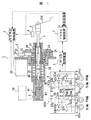
図1は、本発明の第1の実施形態に係る液圧ブレーキ装置1の全体構成を示す図である。なお、FL輪は左前輪、FR輪は右前輪、RL輪は左後輪、RR輪は右後輪をそれぞれ意味する。また、矢印付きの破線は信号線であり、矢印の向きによって信号の流れを表している。
FIG. 1 is a diagram showing an overall configuration of a
図1に示すように、液圧ブレーキ装置1は、ブレーキ力制御手段としてのブレーキ力制御装置2と、第2の加減圧手段としてのマスタ圧制御装置3及びマスタ圧制御機構4と、ホイール圧制御装置5と、ホイール圧制御機構6と、第1の加減圧手段としてのインプットロッド7と、ブレーキセンサ8と、マスタシリンダ9と、リザーバタンク10と、ホイールシリンダ11a〜dとを備えている。なお、第1の加減圧手段には、ブレーキペダル100を含む。また、第2の加減圧手段には、マスタシリンダ9を構成するプライマリピストン40を含む。
As shown in FIG. 1, the
ブレーキ力制御装置2は、演算処理回路であり、ブレーキセンサ8の信号、先行車との車間距離,道路情報,車両状態量等に基づいて各輪で発生させるべき目標ブレーキ力を算出し、この結果に基づいてマスタ圧制御装置3とホイール圧制御装置5に制御指令を送信する。車両状態量としては、例えば、ヨーレート,前後加速度,横加速度,ハンドル舵角,車輪速,車体速等がある。
The brake
なお、ブレーキ力制御装置2と、マスタ圧制御装置3及びホイール圧制御装置5とは双方向の通信を行っており、制御指令,車両状態量,故障情報,作動状態、等を共有している。
The brake
マスタ圧制御装置3は、演算処理回路であり、ブレーキ力制御装置2からの制御指令、ブレーキセンサ8の信号等に基づいて、マスタ圧制御機構4を構成する駆動モータ20の制御を行う。
The master pressure control device 3 is an arithmetic processing circuit, and controls the
マスタ圧制御機構4は、マスタ圧制御装置3の制御指令に従ってプライマリピストン40を押圧するものであり、回転トルクを発生する駆動モータ20と、駆動モータ20の回転トルクを増幅する減速装置21と、回転動力を並進動力に変換する回転−並進変換装置25とを備えている。
The master
ホイール圧制御装置5は、演算処理回路であり、ブレーキ力制御装置2からの制御指令等に基づいてホイール圧制御機構6の制御を行う。
The wheel
ホイール圧制御機構6は、ホイール圧制御装置5の制御指令に従って、マスタシリンダ9で加圧された作動液の各ホイールシリンダ11a〜dへの供給を制御する。
The wheel
インプットロッド7は、ブレーキペダル100に連結され、その片端がプライマリ液室42に挿入されている。このような構成を採ることにより、運転者のブレーキ操作によってもマスタ圧を上昇させられるため、万一駆動モータ20が停止した場合にも、所定のブレーキ力が確保される。また、マスタ圧に応じた力がインプットロッド7を介してブレーキペダル100に作用し、ブレーキペダル反力として運転者に伝達させられるため、上述の構成を採らない場合に必要となる、バネ等のブレーキペダル反力を生成する装置が不要となる。これにより、液圧ブレーキ装置1の小型・軽量化が図られ、車両への搭載性が向上する。
The input rod 7 is connected to the
ブレーキセンサ8は、運転者の要求ブレーキ力を検出するセンサであり、インプットロッド7の変位量を検出するストロークセンサである。 The brake sensor 8 is a sensor that detects the driver's required braking force, and is a stroke sensor that detects the amount of displacement of the input rod 7.
なお、ブレーキセンサ8としては、ストロークセンサを複数個組み合わせた構成が望ましい。これにより、一つのセンサからの信号が途絶えた場合にも、残りのセンサによって運転者のブレーキ要求が検出,認知されるため、フェイルセーフが確保される。 The brake sensor 8 preferably has a combination of a plurality of stroke sensors. Accordingly, even when the signal from one sensor is interrupted, the driver's brake request is detected and recognized by the remaining sensors, so that fail-safe is ensured.
また、ブレーキセンサ8としては、ブレーキペダル100の踏力を検出する踏力センサや、ストロークセンサと踏力センサを組み合わせた構成であっても良い。
Further, the brake sensor 8 may have a configuration in which a pedal force sensor that detects the pedal force of the
マスタシリンダ9は、プライマリピストン40によって加圧されるプライマリ液室42と、セカンダリピストン41によって加圧されるセカンダリ液室43の二つの加圧室を有するタンデム式のものであり、プライマリピストン40の推進によって各加圧室で加圧された作動液が、マスタ配管102a〜bを経由してホイール圧制御機構6に供給されるように構成されている。
The master cylinder 9 is a tandem type having two pressure chambers, a
リザーバタンク10は、図示しない隔壁によって仕切られた少なくとも二つの液室を有するものであり、それぞれの液室はマスタシリンダ9の各加圧室と連通可能に接続されている。
The
ホイールシリンダ11a〜dは、図示しないシリンダ,ピストン,パッド等から構成されており、ホイール圧制御機構6から供給された作動液によってピストンが推進され、ピストンに連結されたパッドがディスクロータ101a〜dに押圧されるものである。
The
なお、ディスクロータ101a〜dは、図示しない車輪とともに回転している。そのため、ディスクロータ101a〜dに作用したブレーキトルクは、車輪と路面との間に作用するブレーキ力となる。 Note that the disk rotors 101a to 101d rotate with wheels (not shown). Therefore, the brake torque acting on the disc rotors 101a to 101d becomes a braking force acting between the wheel and the road surface.
続いて、マスタ圧制御機構4の構成と動作について説明する。
Next, the configuration and operation of the master
前述の通り、マスタ圧制御機構4は駆動モータ20と減速装置21と回転−並進変換装置25とを備えている。
As described above, the master
駆動モータ20は、マスタ圧制御装置3の制御指令に基づいて供給される電力によって動作し、所望の回転トルクを発生する。
The
なお、駆動モータ20としては、DCモータ,DCブラシレスモータ,ACモータ等が適当であるが、制御性,静粛性,耐久性の点においては、DCブラシレスモータが望ましい。
As the
また、駆動モータ20には、図示しない位置センサが備わっており、この信号がマスタ圧制御装置3に入力されるように構成されている。これにより、マスタ圧制御装置3は、位置センサの信号に基づいて駆動モータ20の回転角を算出することができ、これに基づいて回転−並進変換装置25の推進量、すなわちプライマリピストン40の変位量を算出することができる。
Further, the
減速装置21は、駆動モータ20の回転トルクを自身の減速比分だけ増幅させるものである。
The reduction gear 21 amplifies the rotational torque of the
なお、減速の方式としては、歯車減速,プーリ減速等が適当であるが、第1の実施形態では、駆動側プーリ22と従動側プーリ23とベルト24とを備えてなるプーリ減速による方式を採っている。
As a speed reduction method, gear speed reduction, pulley speed reduction, and the like are appropriate, but in the first embodiment, a speed reduction method using a driving
また、駆動モータ20の回転トルクが十分に大きく、減速によるトルクの増幅が必要でない場合には、減速装置21を備えずに駆動モータ20と回転−並進変換装置25とを直結することができる。これにより、減速装置21の介在に起因して発生する、信頼性,静粛性,搭載性等に係る諸問題を回避することができる。
Further, when the rotational torque of the
回転−並進変換装置25は、駆動モータ20の回転動力を並進動力に変換してプライマリピストン40を押圧するものである。
The rotation-
なお、変換の機構としては、ラックピニオン,ボールネジ等が適当であるが、第1の実施形態ではボールネジによる方式を採っている。 As a conversion mechanism, a rack pinion, a ball screw, or the like is appropriate. However, in the first embodiment, a system using a ball screw is adopted.
図1に示すように、ボールネジナット26の外側には従動側プーリ23が嵌合されており、その回転によるボールネジナット26の回転によりボールネジ軸27が並進運動し、この推力によって可動部材28を介してプライマリピストン40が押圧される。
As shown in FIG. 1, a driven
なお、可動部材28には、片端が固定部に接続された戻しバネ29の一端が係合されており、ボールネジ軸27の推力と逆方向の力が可動部材28を介してボールネジ軸27に作用するように構成されている。これにより、ブレーキ中、すなわちプライマリピストン40が押圧されマスタ圧が加圧されている状態において、駆動モータ20が停止しボールネジ軸27の戻し制御が不能となった場合にも、戻しバネ29の反力によってボールネジ軸27が初期位置に戻され、マスタ圧が概ね零付近まで低下するため、ブレーキ力の引きずりに起因して車両挙動が不安定になることが回避される。
The
続いて、マスタ圧制御装置3とマスタ圧制御機構4による、インプットロッド7の推力の増幅について説明する。
Next, amplification of the thrust of the input rod 7 by the master pressure control device 3 and the master
第1の実施形態では、運転者のブレーキ操作によるインプットロッド7の変位量に応じてプライマリピストン40を変位させることで、インプットロッド7の推力が増幅される形でプライマリ液室42が加圧される。その増幅比(以下、倍力比と称す。)は、インプットロッド7とプライマリピストン40の変位量の比、インプットロッド7とプライマリピストン40の断面積(以下、それぞれAIRをAPPと称す。)の比、等によって任意の値に決定される。特に、インプットロッド7の変位量と同量だけプライマリピストン40を変位させた場合には、倍力比は(AIR+APP)/AIRに一意に定まることが一般に知られている。すなわち、必要な倍力比に基づいてAIRとAPPを設定し、変位量がインプットロッド7の変位量に等しくなるようにプライマリピストン40を制御することで、常に一定の倍力比を得ることができる。
In the first embodiment, the
なお、前述の通り、インプットロッド7の変位量はブレーキセンサ8によって検出される。 As described above, the displacement amount of the input rod 7 is detected by the brake sensor 8.
また、プライマリピストン40の変位量は、図示しない位置センサの信号に基づいてマスタ圧制御装置3によって算出される。
Further, the displacement amount of the
続いて、ホイール圧制御機構6の構成と動作について説明する。
Next, the configuration and operation of the wheel
図1に示すように、ホイール圧制御機構6は、マスタシリンダ9で加圧された作動液の各ホイールシリンダ11a〜dへの供給を制御するゲートOUT弁50a〜bと、マスタシリンダ9で加圧された作動液のポンプ54a〜bへの供給を制御するゲートIN弁51a〜bと、マスタシリンダ9またはポンプ54a〜bから各ホイールシリンダ11a〜dへの作動液の供給を制御するIN弁52a〜dと、ホイールシリンダ11a〜dを減圧制御するOUT弁53a〜dと、マスタシリンダ9で生成された作動圧を昇圧するポンプ54a〜bと、ポンプ54a〜bを駆動するポンプモータ55と、マスタ圧を検出するマスタ圧センサ56とを備えている。
As shown in FIG. 1, the wheel
なお、ホイール圧制御機構6としては、アンチロックブレーキ制御用の液圧制御ユニット,車両挙動安定化制御用の液圧制御ユニット,ブレーキバイワイヤ用の液圧制御ユニット等が適当である。
As the wheel
また、ホイール圧制御機構6は、プライマリ液室42から作動液の供給を受け、FL輪とRR輪のブレーキ力を制御する第1のブレーキ系統と、セカンダリ液室43から作動液の供給を受け、FR輪とRL輪のブレーキ力を制御する第2のブレーキ系統の二つの系統から構成されている。このような構成を採ることにより、一方のブレーキ系統が失陥した場合にも、正常なもう一方のブレーキ系統によって対角2輪分のブレーキ力が確保されるため、車両の挙動が安定に保たれる。
Further, the wheel
図1において、ゲートOUT弁50a〜bは、マスタシリンダ9とIN弁52a〜dとの間に備えられており、マスタシリンダ9で加圧された作動液をホイールシリンダ11a〜dに供給する際に開弁される。
In FIG. 1, gate OUT
ゲートIN弁51a〜bは、マスタシリンダ9とポンプ54a〜bとの間に備えられており、マスタシリンダ9で加圧された作動液をポンプ54a〜bで昇圧してホイールシリンダ11a〜dに供給する際に開弁される。
The gate IN
IN弁52a〜dは、ホイールシリンダ11a〜dの上流に備えられており、マスタシリンダ9またはポンプ54a〜bで加圧された作動液をホイールシリンダ11a〜dに供給する際に開弁される。
The IN valves 52a to 52d are provided upstream of the
OUT弁53a〜dは、ホイールシリンダ11a〜dの下流に備えられており、ホイール圧を減圧する際に開弁される。
The OUT valves 53a to 53d are provided downstream of the
なお、ゲートOUT弁50a〜bとゲートIN弁51a〜bとIN弁52a〜dとOUT弁53a〜dは、内部の図示しないソレノイドへの通電によって弁の開閉が行われる電磁式のものであり、ホイール圧制御装置5が行う電流制御によって弁の開閉量が各弁個々に調節される。
The gate OUT
また、ゲートOUT弁50a〜bとゲートIN弁51a〜bとIN弁52a〜dとOUT弁53a〜dは、常開弁,常閉弁のいずれであっても構わないが、第1の実施形態では、ゲートOUT弁50a〜bとIN弁52a〜dが常開弁、ゲートIN弁51a〜bとOUT弁53a〜dが常閉弁である。このような構成を採ることにより、それぞれの弁への電力供給が停止した場合にも、ゲートIN弁51a〜bとOUT弁53a〜dが閉じ、ゲートOUT弁50a〜bとIN弁52a〜dが開いて、マスタシリンダ9で加圧された作動液がすべてのホイールシリンダ11a〜dに到達するため、運転者の要求通りのブレーキ力を発生させることができる。
The gate OUT
ポンプ54a〜bは、例えば、車両挙動安定化制御,自動ブレーキ等を行うために、マスタシリンダ9の作動圧を超える圧力が必要な場合に、マスタ圧を昇圧してホイールシリンダ11a〜dに供給する。
The pumps 54a to 54b increase the master pressure and supply it to the
なお、ポンプ54a〜bとしては、プランジャポンプ,トロコイドポンプ,ギヤポンプ等が適当であるが、静粛性の点においてはギヤポンプが望ましい。
As the
ポンプモータ55は、ホイール圧制御装置5の制御指令に基づいて供給される電力によって動作し、自身に連結されたポンプ54a〜bを駆動する。
The
なお、ポンプモータ55としては、DCモータ,DCブラシレスモータ,ACモータ等が適当であるが、制御性,静粛性,耐久性の点においてはDCブラシレスモータが望ましい。
As the
マスタ圧センサ56は、セカンダリ側のマスタ配管102bの下流に備えられており、マスタ圧を検出する圧力センサである。
The
なお、マスタ圧センサ56の個数及び設置位置に関しては、制御性,フェイルセーフ等を考慮して任意に決定することができる。
The number and installation positions of the
本発明の実施形態に係る液圧ブレーキ装置1で行われる処理、特に、自動ブレーキを実施する際の処理と、自動ブレーキ中に運転者がブレーキ操作を行った場合の処理について、図2〜図5を参照しながら以下、説明する。
FIG. 2 to FIG. 2 show processing performed by the
まず、ブレーキ力制御装置2が実行する第1の自動ブレーキ制御ルーチン(以下、第1のルーチンと称す。)と、第2の自動ブレーキ制御ルーチン(以下、第2のルーチンと称す。)で実行されるプライマリピストン40の制御処理、具体的には、マスタ圧制御処理,第1の制御処理,第2の制御処理,第3の制御処理について説明する。
First, a first automatic brake control routine (hereinafter referred to as a first routine) executed by the brake
マスタ圧制御処理は、マスタシリンダ9の作動圧を自動ブレーキの要求液圧(以下、自動ブレーキ要求液圧と称す。)に調節すべく、プライマリピストン40を前進及び後退させる制御処理である。
The master pressure control process is a control process for moving the
なお、この場合のプライマリピストン40の制御方法としては、テーブルとして事前に取得したプライマリピストン40の変位量とマスタ圧との関係に基づいて、自動ブレーキ要求液圧を実現するプライマリピストン40の変位量を抽出し、これを目標値とする方法、マスタ圧センサ56で検出されたマスタ圧をフィードバックする方法等があるが、いずれの方法を採っても構わない。
As a control method of the
第1の制御処理は、インプットロッド7の変位量に比例ゲイン(以下、K1と称す。)を乗じた量だけプライマリピストン40を変位させる制御処理である。
The first control process is a control process for displacing the
なお、K1は制御性の点からは1であることが望ましいが、緊急ブレーキ等により運転者のブレーキ操作量を上回るブレーキ力が必要な場合には、一時的に、K1を、1を上回る値に変更することができる。これにより、同量のブレーキ操作量でも、マスタ圧を通常時(K1=1の場合)に比べて引き上げられるため、より大きなブレーキ力を発生させることができる。ここで、緊急ブレーキの判定は、例えば、ブレーキセンサ8の信号の時間変化率が所定値を上回るか否かで判定することができる。 K 1 is preferably 1 from the viewpoint of controllability. However, if a braking force exceeding the driver's brake operation amount is required due to emergency braking or the like, temporarily set K 1 to 1. It can be changed to a higher value. As a result, even with the same amount of brake operation, the master pressure can be increased compared to the normal time (when K 1 = 1), so that a larger braking force can be generated. Here, the emergency brake can be determined, for example, based on whether or not the time change rate of the signal of the brake sensor 8 exceeds a predetermined value.
以上述べた通り、第1の制御処理によれば、運転者のブレーキ要求に従うインプットロッド7の変位量に応じてマスタ圧が増減圧されるため、運転者の要求通りのブレーキ力を発生させることができる。 As described above, according to the first control process, the master pressure is increased or decreased according to the displacement amount of the input rod 7 according to the driver's brake request, so that the braking force as requested by the driver is generated. Can do.
第2の制御処理は、所定のオフセット量だけプライマリピストン40を推進させたうえで、第1の制御処理を実行する制御処理である。
The second control process is a control process for executing the first control process after propelling the
第2の制御処理は、例えば、車線逸脱回避制御,障害物回避制御等により、左右片側の2輪のみに自動ブレーキの作動圧を作用させている状態(以下、2輪ブレーキと称す。)から、運転者のブレーキ要求に従って4輪すべてに作動圧を作用させる状態(以下、4輪ブレーキと称す。)に切り替える必要性が生じた場合に適用されるものであり、主に、2輪ブレーキから4輪ブレーキに切り替わる際に発生する作動液量の不足を回避することを狙いとした制御処理である。すなわち、第2の制御処理によれば、作動液量の減少に起因するマスタ圧の低下が抑制されるため、マスタ圧の低下に伴うブレーキ力の低下が回避される。 In the second control process, for example, the automatic brake operating pressure is applied to only the two wheels on the left and right sides by lane departure avoidance control, obstacle avoidance control, and the like (hereinafter referred to as two-wheel brake). This is applied when there is a need to switch to a state in which operating pressure is applied to all four wheels (hereinafter referred to as a four-wheel brake) in accordance with the driver's brake requirements. This is a control process aimed at avoiding the shortage of hydraulic fluid generated when switching to a four-wheel brake. That is, according to the second control process, a decrease in master pressure due to a decrease in the amount of hydraulic fluid is suppressed, so that a decrease in braking force accompanying a decrease in master pressure is avoided.
なお、オフセット量の決定方法としては、例えば以下、の二つがあるが、いずれの方法を採っても構わない。 Note that there are the following two methods for determining the offset amount, but either method may be employed.
第1の決定方法は、テーブルとして事前に取得した、2輪ブレーキ時及び4輪ブレーキ時それぞれのプライマリピストン40の変位量とマスタ圧との関係に基づいて、目標ブレーキ液圧を実現するプライマリピストン40の変位量を2輪ブレーキ時と4輪ブレーキ時でそれぞれ抽出し、両者の差分(4輪ブレーキ時の変位量−2輪ブレーキ時の変位量)をオフセット量とする方法である。
The first determination method is a primary piston that realizes a target brake hydraulic pressure based on the relationship between the master pressure and the displacement amount of the
第2の決定方法は、2輪ブレーキから4輪ブレーキに切り替わる際に、マスタ圧が目標ブレーキ液圧に到達するように、マスタ圧センサ56の出力を参照するフィードバック制御を行い、これによりプライマリピストン40を推進させる方法である。
The second determination method performs feedback control that refers to the output of the
なお、目標ブレーキ液圧については、運転者のブレーキ要求に応じて任意に決定することができるが、例えば、自動ブレーキ要求液圧であっても構わない。 The target brake fluid pressure can be arbitrarily determined according to the driver's brake request, but may be an automatic brake request fluid pressure, for example.
また、第2の制御処理において実行される第1の制御処理は、前述した第1の制御処理と同じである。 Further, the first control process executed in the second control process is the same as the first control process described above.
以上述べた通り、第2の制御処理によれば、2輪ブレーキから4輪ブレーキに切り替わる際のマスタ圧の低下が抑制されるように、第1の制御処理とは別にプライマリピストン40の制御が行われるため、運転者の要求通りのブレーキ力を発生させることができる。
As described above, according to the second control process, the
第3の制御処理は、インプットロッド7の変位量に比例ゲイン(以下、K3と称す。)を乗じた量だけプライマリピストン40を変位させる制御処理である。
The third control process is a control process for displacing the
第3の制御処理は、運転者のブレーキ要求が特に減圧要求である場合に適用されるものであり、インプットロッド7の変位量が概ね零に達すると同時にマスタ圧が概ね零に達するようにプライマリピストン40を変位させる制御である。
The third control process is applied particularly when the driver's brake request is a pressure reduction request. The primary control process is such that the master pressure reaches approximately zero at the same time that the displacement amount of the input rod 7 reaches approximately zero. This is control for displacing the
なお、K3としては、第3の制御処理開始時におけるインプットロッド7とプライマリピストン40の変位量の初期値(以下、それぞれXIR0,XPP0と称す。)を記憶しておき、これらの比であるXPP0/XIR0が適当である。ここで、K3の決定に際しては、XPP0にマスタシリンダ9の無効ストローク量を考慮しても良い。
As K 3 , initial values of displacement amounts of the input rod 7 and the
以上述べた通り、第3の制御処理によれば、運転者のブレーキ要求が概ね零に達した段階でマスタ圧が概ね零に達するように、プライマリピストン40の制御が行われるため、運転者の要求通りのブレーキ力を発生させることができる。
As described above, according to the third control process, the
図2は、ブレーキ力制御装置2が実行する第1のルーチンのフローチャートを示す図である。
FIG. 2 is a flowchart of a first routine executed by the braking
なお、第1のルーチンは、4輪ブレーキによる制御、例えば、車間距離制御,衝突回避制御等に適用される。 The first routine is applied to control by four-wheel brake, for example, inter-vehicle distance control, collision avoidance control, and the like.
また、第1のルーチンは、所定の時間間隔で繰り返し起動される。 Further, the first routine is repeatedly started at a predetermined time interval.
第1のルーチンが起動されると、まず、ステップ100の処理が実行される。
When the first routine is started, first, the process of
ステップ100では、自動ブレーキの継続が可能か否かが判定され、これが成立する場合にはステップ101の処理が実行され、成立しない場合にはステップ102の処理が実行される。
In
なお、ステップ100では、例えば、運転者がブレーキ操作を行っていない場合や、マスタ圧が自動ブレーキ要求液圧に等しいかまたは下回る場合等に自動ブレーキの継続が可能と判定される。
In
ステップ101では、マスタ圧制御処理が実行され、マスタシリンダ9の作動圧が自動ブレーキ要求液圧に調節される。
In
なお、この場合の自動ブレーキ要求液圧は、ブレーキ力制御装置2において算出された目標ブレーキ力に基づいて決定される。
Note that the automatic brake required hydraulic pressure in this case is determined based on the target brake force calculated by the brake
ステップ102では、自動ブレーキを解除するか否かが判定され、これが成立する場合にはステップ103の処理が実行され、成立しない場合にはステップ104の処理が実行される。
In
なお、ステップ102では、例えば、車両状態量,先行車との車間距離等に基づいて自動ブレーキを解除するか否かが判定される。
In
但し、衝突被害軽減ブレーキ制御を行っている場合には、自動ブレーキを解除しないことが望ましい。 However, it is desirable not to release the automatic brake when the collision damage reduction brake control is performed.
ステップ103では、運転者のブレーキ要求が、増圧要求または保持要求であるか否かが判定され、これが成立する場合にはステップ105の処理が実行され、成立しない場合にはステップ106の処理が実行される。
In
なお、ステップ103では、例えば、ブレーキセンサ8によって検出されるインプットロッド7の変位量の時間変化率に基づいて、増圧要求,保持要求,減圧要求のいずれかが判定される。
In
ステップ105では、第1の制御処理が実行され、これにより今回のルーチンは終了する。
In
ステップ106では、第3の制御処理が実行され、これにより今回のルーチンは終了する。
In
ステップ104では、ステップ103と同様に、運転者のブレーキ要求が増圧要求または保持要求であるか否かが判定され、これが成立する場合にはステップ107の処理が実行され、成立しない場合にはステップ108の処理が実行される。
In
ステップ107では、第1の制御処理が実行され、これにより今回のルーチンは終了する。
In
ステップ108では、第1の制御処理が実行される。
In
ステップ109では、マスタ圧(PMC)が自動ブレーキ要求液圧(PDMND)に等しいか、または下回るか否かが判定され、これが成立する場合にはステップ110の処理が行われ、成立しない場合には今回のルーチンは終了する。
In
ステップ110では、自動ブレーキ移行処理が実行される。
In
なお、自動ブレーキ移行処理は、例えば、自動ブレーキ可能フラグをオンにする処理である。 The automatic brake transition process is a process of turning on an automatic brake enable flag, for example.
以上述べた通り、ブレーキ力制御装置2が実行する第1のルーチンによれば、適切な自動ブレーキが実現されるとともに、自動ブレーキ中に運転者がブレーキ操作を行った場合においても、自動ブレーキの解除条件,運転者のブレーキ要求、等に基づいてプライマリピストン40の制御処理が適切に選択され、実行されるため、ブレーキ時の車両挙動が安定化するとともに、ブレーキペダル100の操作性が向上する。
As described above, according to the first routine executed by the brake
図3は、第1のルーチンが起動している場合の各状態量のタイムチャートを示す図である。なお、ここでは、一例としてステップ102において自動ブレーキが解除される場合を想定しているが、他の場合においても、図2に示すフローチャートに従って適切な制御処理が選択,実行される。
FIG. 3 is a diagram illustrating a time chart of each state quantity when the first routine is activated. Here, as an example, it is assumed that the automatic brake is released in
以下、各状態量の変化をチャートに従って説明する。 Hereinafter, changes in each state quantity will be described with reference to the chart.
まず、自動ブレーキオンからブレーキペダル100オンまでの期間では、マスタ圧が自動ブレーキ要求液圧に維持されるように、マスタ圧制御によってプライマリピストン40の制御が行われる。
First, during the period from automatic brake on to
第1のルーチンでは、すべての輪のIN弁52a〜dが開状態にあるため、各ホイール圧はマスタ圧に概ね等しく制御される。これにより、目標ブレーキ力に合致した減速度が実現される。 In the first routine, since the IN valves 52a to 52d of all the wheels are in the open state, each wheel pressure is controlled approximately equal to the master pressure. As a result, deceleration that matches the target braking force is realized.
つぎに増圧要求の期間では、ブレーキペダル100踏力が、自動ブレーキ要求液圧に維持されているマスタ圧に応じた力を上回った段階でインプットロッド7が変位し始め、これと同時に第1の制御によってプライマリピストン40の制御が開始される。
Next, in the period of the pressure increase request, the input rod 7 starts to be displaced at the stage where the depression force of the
なお、インプットロッド7が変位し始めた段階で、ブレーキセンサ8により運転者のブレーキ要求が検出されるため、これに基づいて自動ブレーキ要求液圧が零に引き下げられている。 When the input rod 7 begins to be displaced, the brake sensor 8 detects the driver's brake request, and based on this, the automatic brake request hydraulic pressure is reduced to zero.
つぎに保持要求の期間では、増圧要求の期間と同様に、第1の制御によってプライマリピストン40の制御が継続され、これにより、所定の減速度が維持される。
Next, in the holding request period, similarly to the pressure increasing request period, the control of the
つぎに減圧要求の期間では、第3の制御によってプライマリピストン40の制御が行われ、これにより、所定の減速度が実現される。
Next, in the period of pressure reduction request, the
なお、図2のフローチャートに示すように、第3の制御中に、運転者のブレーキ要求が増圧要求または保持要求に切り替わった場合には、第1の制御に切り替えることができる。 As shown in the flowchart of FIG. 2, when the driver's brake request is switched to a pressure increase request or a holding request during the third control, the control can be switched to the first control.
図4は、ブレーキ力制御装置2が実行する第2のルーチンのフローチャートを示す図である。なお、第2のルーチンは、2輪ブレーキによる制御、例えば、車線逸脱回避制御,障害物回避制御等に適用される。また、第2のルーチンは所定の時間間隔で繰り返し起動される。
FIG. 4 is a flowchart of a second routine executed by the brake
第2のルーチンが起動されると、まず、ステップ200の処理が実行される。
When the second routine is started, first, the process of
ステップ200では、自動ブレーキの継続が可能か否かが判定され、これが成立する場合にはステップ201の処理が実行され、成立しない場合にはステップ202の処理が実行される。
In
なお、ステップ200では、例えば、運転者がブレーキ操作を行っていない場合や、マスタ圧が自動ブレーキ要求液圧に等しいかまたは下回る場合等に自動ブレーキの継続が可能と判定される。
In
ステップ201では、自動ブレーキを行わない輪(以下、非制御輪と称す。)のIN弁52a〜dが閉弁され、かつホイール圧の減圧が完了しているか否かが判定され、これが成立する場合にはステップ204の処理が実行され、成立しない場合にはステップ203の処理が実行される。
In
ステップ203では、非制御輪のIN弁52a〜dを閉弁するとともにホイール圧を減圧する処理が実行される。これにより、非制御輪のホイールシリンダ11a〜dにマスタシリンダ9で加圧された作動液が供給されなくなるとともに、4輪ブレーキ時のホイール圧が概ね零に低下するため、自動ブレーキを行う輪(以下、制御輪と称す。)のみにブレーキ力を発生させることができる。
In
ステップ204では、マスタ圧制御処理が実行され、マスタシリンダ9の作動圧が自動ブレーキ要求液圧に調節される。
In
なお、この場合の自動ブレーキ要求液圧は、ブレーキ力制御装置2において算出された目標ブレーキ力に基づいて決定される。
Note that the automatic brake required hydraulic pressure in this case is determined based on the target brake force calculated by the brake
ステップ202では、非制御輪のIN弁52a〜dが開弁されているか否かが判定され、これが成立する場合にはステップ206の処理が実行され、成立しない場合にはステップ205の処理が実行される。
In
ステップ205では、非制御輪のIN弁52a〜dを開弁する処理が実行される。これにより、非制御輪のホイールシリンダ11a〜dにもマスタシリンダ9で加圧された作動液が供給されるようになるため、4輪すべてでブレーキ力を発生させることができる。
In
ステップ206では、自動ブレーキを解除するか否かが判定され、これが成立する場合にはステップ207の処理が実行され、成立しない場合にはステップ208の処理が実行される。
In
なお、ステップ206では、例えば、車両状態量,先行車との車間距離等に基づいて自動ブレーキを解除するか否かが判定される。
In
但し、衝突被害軽減ブレーキ制御を行っている場合には、自動ブレーキを解除しないことが望ましい。 However, it is desirable not to release the automatic brake when the collision damage reduction brake control is performed.
ステップ207では、運転者のブレーキ要求が増圧要求または保持要求であるか否かが判定され、これが成立する場合にはステップ209の処理が実行され、成立しない場合にはステップ210の処理が実行される。
In
なお、ステップ207では、例えば、ブレーキセンサ8によって検出されるインプットロッド7の変位量の時間変化率に基づいて、増圧要求,保持要求,減圧要求のいずれかが判定される。
In
ステップ209では、第2の制御処理が実行され、これにより今回のルーチンは終了する。
In
ステップ210では、第3の制御処理が実行され、これにより今回のルーチンは終了する。
In
ステップ208では、ステップ207と同様に、運転者のブレーキ要求が増圧要求または保持要求であるか否かが判定され、これが成立する場合には、ステップ211の処理が実行され、成立しない場合にはステップ212の処理が実行される。
In
ステップ211では、第2の制御処理が実行され、これにより今回のルーチンは終了する。 In step 211, the second control process is executed, thereby ending this routine.
ステップ212では、第1の制御処理が実行される。
In
ステップ213では、マスタ圧(PMC)が自動ブレーキ要求液圧(PDMND)に等しいかまたは下回るか否かが判定され、これが成立する場合にはステップ214の処理が行われ、成立しない場合には今回のルーチンは終了する。
In step 213, whether the master pressure (P MC) is equal to or below the automatic braking request hydraulic pressure (P dmnd) is determined, the process of
ステップ214では、自動ブレーキ移行処理が実行される。
In
なお、自動ブレーキ移行処理は、例えば、自動ブレーキ可能フラグをオンにする処理である。 The automatic brake transition process is a process of turning on an automatic brake enable flag, for example.
以上述べた通り、ブレーキ力制御装置2が実行する第2のルーチンによれば、適切な自動ブレーキが実現されるとともに、自動ブレーキ中に運転者がブレーキ操作を行った場合においても、自動ブレーキの解除条件,運転者のブレーキ要求、等に基づいてプライマリピストン40の制御処理が適切に選択され、実行されるため、ブレーキ時の車両挙動が安定化するとともに、ブレーキペダル100の操作性が向上する。
As described above, according to the second routine executed by the brake
図5は、第2のルーチンが起動している場合の各状態量のタイムチャートを示す図である。なお、ここでは、一例としてステップ206において自動ブレーキが解除されない場合を想定しているが、他の場合においても、図4に示すフローチャートに従って適切な制御処理が選択,実行される。また、ここでは、制御輪がFL輪とRL輪の左側2輪である場合を示しているが、他の場合においても、図4に示すフローチャートに従って適切な制御処理が選択,実行される。
FIG. 5 is a diagram illustrating a time chart of each state quantity when the second routine is activated. Here, as an example, it is assumed that the automatic brake is not released in
以下、各状態量の変化をチャートに従って説明する。 Hereinafter, changes in each state quantity will be described with reference to the chart.
まず、自動ブレーキオンからブレーキペダル100オンまでの期間では、マスタ圧が自動ブレーキ要求液圧に維持されるように、マスタ圧制御によってプライマリピストン40の制御が行われる。
First, during the period from automatic brake on to
なお、自動ブレーキオンに先立って、非制御輪であるFR輪とRR輪のIN弁52b,dが閉弁されている。
Prior to the automatic brake-on, the FR wheels and the RR wheels IN
つぎに増圧要求の期間では、ブレーキペダル100踏力が自動ブレーキ要求液圧に維持されているマスタ圧に応じた力を上回った段階で、インプットロッド7が変位し始め、これと同時に第2の制御によってプライマリピストン40の制御が開始される。
Next, in the period of the pressure increase request, the input rod 7 starts to be displaced at the stage when the depression force of the
なお、インプットロッド7が変位し始めた段階で、ブレーキセンサ8により運転者のブレーキ要求が検出されるため、これに基づいて非制御輪であるFR輪とRR輪のIN弁52b,dが開弁されている。この時、それぞれのIN弁52b,dの開弁のタイミングをずらしてもよい。これにより、プライマリピストン40の変位量の時間変化率が小さく抑えられるため、減速度の変化がさらに改善される。
When the input rod 7 starts to be displaced, the brake sensor 8 detects the driver's brake request. Based on this, the FR valves and the RR wheel IN
つぎに保持要求の期間では、増圧要求の期間と同様に、第2の制御によってプライマリピストン40の制御が継続され、これにより、所定の減速度が維持される。
Next, in the holding request period, similarly to the pressure increase request period, the control of the
つぎに減圧要求の期間では、第1の制御によってプライマリピストン40の制御が行われ、これにより、所定の減速度が実現される。
Next, in the period of the pressure reduction request, the
なお、インプットロッド7の変位量が概ね零に達した段階で、ブレーキセンサ8の信号に基づいて運転者のブレーキ要求が解除されたと判断されるため、これに基づいて2輪ブレーキを継続すべく、非制御輪であるFR輪とRR輪のIN弁52b,dが閉弁されている。
Note that when the displacement amount of the input rod 7 reaches approximately zero, it is determined that the driver's brake request has been released based on the signal from the brake sensor 8, so that the two-wheel brake should be continued based on this. The
以上述べた通り、本発明の第1の実施形態に係る液圧ブレーキ装置1によれば、自動ブレーキ中に運転者がブレーキ操作を行った場合においても、運転者の要求通りのブレーキ力を発生させられるため、ブレーキ時の車両挙動が安定化するとともに、ブレーキペダル100の操作性が向上する。
As described above, according to the
図6は、本発明の第2の実施形態に係る液圧ブレーキ装置1の全体構成を示す図である。なお、第1の実施形態と同一部分については、同一番号を付して説明を省略する。
FIG. 6 is a diagram showing an overall configuration of the
第2の実施形態が第1の実施形態と異なる点は、インプットロッド7がプライマリ液室42に挿入されていない点、可動部材28に伝達部材30が連結されている点、インプットロッド7と伝達部材30とが空隙もって配設されている点、ブレーキペダル100に反力生成機構103が連結されている点である。ここで、反力生成機構103は、ブレーキ力制御装置2の制御指令に従って所定の反力を生成し、これをブレーキペダル100に作用させるものである。
The second embodiment is different from the first embodiment in that the input rod 7 is not inserted into the
すなわち、ブレーキ力制御装置2が実行する第1のルーチンと、第2のルーチンで実行されるプライマリピストン40の制御処理は第1の実施形態となんら変わらないため、第1の実施形態と同様に、自動ブレーキ中に運転者がブレーキ操作を行った場合においても、運転者の要求通りのブレーキ力を発生させることができる。
That is, the control process of the
なお、第2の実施形態においても、第1の実施形態と同様に、運転者のブレーキ操作によるインプットロッド7の変位量に応じてプライマリピストン40を変位させることで、インプットロッド7の推力が増幅される形でプライマリ液室42を加圧することができる。
Also in the second embodiment, as in the first embodiment, the thrust of the input rod 7 is amplified by displacing the
また、万一駆動モータ20が停止した場合にも、運転者のブレーキペダル100踏力がインプットロッド7,伝達部材30,可動部材28を介してプライマリピストン40に伝達されマスタ圧が上昇するため、所定のブレーキ力が確保される。
Even if the
また、インプットロッド7がプライマリ液室42に挿入されていないことにより、マスタ圧に応じた力がブレーキペダル100に作用しないため、ハイブリッド車,電気自動車等で行われる回生協調制動の際に、マスタ圧の変動の影響を受けることがない。
In addition, since the input rod 7 is not inserted into the
また、反力生成機構103により、ブレーキペダル100反力を任意に決定できるため、ブレーキペダル100の操作感を容易に変更することができる。
Further, since the reaction
以上、本発明の実施形態を図面に従って説明したが、これらはあくまでも一つの実施形態であり、本発明は当業者の知識に基づいて種々の変更,改良を加えた態様で実施することができる。 As mentioned above, although embodiment of this invention was described according to drawing, these are one embodiment to the last, and this invention can be implemented in the aspect which added the various change and improvement based on the knowledge of those skilled in the art.
1 液圧ブレーキ装置
2 ブレーキ力制御装置
3 マスタ圧制御装置
4 マスタ圧制御機構
5 ホイール圧制御装置
6 ホイール圧制御機構
7 インプットロッド
8 ブレーキセンサ
9 マスタシリンダ
10 リザーバタンク
11a〜d ホイールシリンダ
20 駆動モータ
21 減速装置
22 駆動側プーリ
23 従動側プーリ
24 ベルト
25 回転−並進変換装置
26 ボールネジナット
27 ボールネジ軸
28 可動部材
29 戻しバネ
30 伝達部材
40 プライマリピストン
41 セカンダリピストン
42 プライマリ液室
43 セカンダリ液室
50a〜b ゲートOUT弁
51a〜b ゲートIN弁
52a〜d IN弁
53a〜d OUT弁
54a〜b ポンプ
55 ポンプモータ
56 マスタ圧センサ
100 ブレーキペダル
101a〜d ディスクロータ
102a〜b マスタ配管
103 反力生成機構
DESCRIPTION OF
Claims (6)
前記ブレーキ力制御手段は、目標マスタシリンダ圧に応じて前記第2の加減圧手段を制御するマスタ圧制御処理と、前記第1の加減圧手段の変位に応じて前記第2の加減圧手段を制御するブレーキ制御処理と、を有し、
前記マスタ圧制御処理において動作させているホイールシリンダの個数に応じて、前記ブレーキ制御処理における前記第2の加減圧手段の制御方式が異なり、
前記マスタ圧制御処理中に運転者のブレーキ操作により前記第1の加減圧手段が動作した場合に、前記ブレーキ制御処理を開始することを特徴とする液圧ブレーキ装置。 A first pressurizing and depressurizing means for pressurizing adjusting the master cylinder, a second pressurizing and depressurizing means for pressurizing adjusting the master cylinder independently of the first pressurizing and depressurizing means, calculates a target braking force, the target braking a braking force control means for determining a target master cylinder pressure based on the force, the hydraulic brake device including a plurality of wheel cylinders operated by working fluid pressure supplied from the master cylinder, and
The brake force control means includes a master pressure control process of controlling the second pressurizing and depressurizing means in accordance with the target master cylinder pressure, the second pressurizing and depressurizing means in accordance with the displacement of the first pressurizing and depressurizing means a brake control process for controlling, and
Depending on the number of wheel cylinders operated in the master pressure control process, the control method of the second pressure increasing / decreasing means in the brake control process is different.
Hydraulic brake device, wherein the first pressurizing and depressurizing means by OPERATION's brake operation in the master pressure control processing when operation starts the brake control process.
前記ブレーキ制御処理における前記第2の加減圧手段の制御方式には、前記第1の加減圧手段の変位量に比例した量だけ前記第2の加減圧手段を変位させる第1の制御処理と、前記第1の加減圧手段の変位量に比例した量に所定の変位量を上乗せした量だけ前記第2の加減圧手段を変位させる第2の制御処理と、前記第1の加減圧手段の変位量が零位置に戻った状態で前記第2の加減圧手段による前記マスタシリンダの加圧が解除されるように前記第2の加減圧手段を変位させる第3の制御処理のいずれか、またはすべてが含まれることを特徴とする液圧ブレーキ装置。 The hydraulic brake device according to claim 1 ,
The control method of the second pressurizing and depressurizing means in the brake control process, a first control process for displacing the first by an amount proportional to the displacement of the pressure regulating means and the second pressurizing and depressurizing means, displacement of said first and second control processing for displacing only said second pressurizing and depressurizing means an amount obtained by adding a predetermined amount of displacement amount proportional to the displacement of the pressurizing and depressurizing means, said first pressurizing and depressurizing means one of the third control process of amount displaces the second pressurizing and depressurizing means so that the pressure of the master cylinder by the second pressurizing and depressurizing means in a state of returning to zero position is released, or all A hydraulic brake device comprising:
前記マスタ圧制御処理においてすべてのホイールシリンダを動作させている場合には、前記ブレーキ制御処理において、前記第1の加減圧手段の動作が前記マスタシリンダを加圧する方向に動作した場合に前記第1の制御処理を選択し、前記第1の加減圧手段の動作が前記マスタシリンダを減圧する方向に動作した場合に前記第1の制御処理または前記第3の制御処理を選択することを特徴とする液圧ブレーキ装置。 In the hydraulic brake device according to claim 2 ,
When said master pressure are running all the wheel cylinders in control process, the in brake control process, the first when the operation of the first pressurizing and depressurizing means is operated in a direction to pressurize the master cylinder select the control process, the operation of the first pressurizing and depressurizing means and selects said first control process or the third control process when operated in a direction for reducing the pressure of the master cylinder Hydraulic brake device.
前記マスタ圧制御処理において少なくとも1輪以上のホイールシリンダを動作させていない場合には、前記ブレーキ制御処理において、前記第1の加減圧手段の動作が前記マスタシリンダを加圧する方向に動作した場合に前記第2の制御処理を選択し、前記第1の加減圧手段の動作が前記マスタシリンダを減圧する方向に動作した場合に前記第1の制御処理または前記第3の制御処理を選択することを特徴とする液圧ブレーキ装置。 In the hydraulic brake device according to claim 2 ,
In the master pressure control processing when not operated at least one or more wheels of the wheel cylinder, in the brake control process, when the operation of the first pressurizing and depressurizing means is operated in a direction to pressurize the master cylinder select the second control process, that the operation of the first pressurizing and depressurizing means selects the first control process or the third control process when operated in a direction for reducing the pressure of the master cylinder A hydraulic brake device.
前記第1の加減圧手段は、前記第2の加減圧手段を動作させることで前記マスタシリンダを加減圧することを特徴とする液圧ブレーキ装置。 The hydraulic brake device according to any one of claims 1 to 4 ,
Wherein the first pressurizing and depressurizing means, a hydraulic brake device, characterized in that pressure adjusting the said master cylinder by operating the second pressurizing and depressurizing means.
Priority Applications (3)
| Application Number | Priority Date | Filing Date | Title |
|---|---|---|---|
| JP2007195317A JP4881807B2 (en) | 2007-07-27 | 2007-07-27 | Hydraulic brake device |
| EP08012954.7A EP2019010B1 (en) | 2007-07-27 | 2008-07-17 | Hydraulic braking device |
| US12/179,440 US20090026835A1 (en) | 2007-07-27 | 2008-07-24 | Hydraulic Braking Device |
Applications Claiming Priority (1)
| Application Number | Priority Date | Filing Date | Title |
|---|---|---|---|
| JP2007195317A JP4881807B2 (en) | 2007-07-27 | 2007-07-27 | Hydraulic brake device |
Publications (2)
| Publication Number | Publication Date |
|---|---|
| JP2009029265A JP2009029265A (en) | 2009-02-12 |
| JP4881807B2 true JP4881807B2 (en) | 2012-02-22 |
Family
ID=39828998
Family Applications (1)
| Application Number | Title | Priority Date | Filing Date |
|---|---|---|---|
| JP2007195317A Active JP4881807B2 (en) | 2007-07-27 | 2007-07-27 | Hydraulic brake device |
Country Status (3)
| Country | Link |
|---|---|
| US (1) | US20090026835A1 (en) |
| EP (1) | EP2019010B1 (en) |
| JP (1) | JP4881807B2 (en) |
Families Citing this family (23)
| Publication number | Priority date | Publication date | Assignee | Title |
|---|---|---|---|---|
| JP5107075B2 (en) * | 2008-01-31 | 2012-12-26 | トヨタ自動車株式会社 | Braking device |
| JP5066004B2 (en) * | 2008-06-06 | 2012-11-07 | 日立オートモティブシステムズ株式会社 | Brake system |
| JP5304274B2 (en) * | 2009-01-29 | 2013-10-02 | 日産自動車株式会社 | Brake control device for vehicle |
| WO2010119889A1 (en) * | 2009-04-14 | 2010-10-21 | 本田技研工業株式会社 | Bbw brake device |
| DE102009028034A1 (en) | 2009-07-27 | 2011-02-03 | Robert Bosch Gmbh | Hydraulic master cylinder |
| JP5400716B2 (en) * | 2010-06-30 | 2014-01-29 | 日立建機株式会社 | Driving force control device for electric vehicle |
| DE102010042694A1 (en) * | 2010-07-27 | 2012-02-02 | Robert Bosch Gmbh | Coupling device for connecting a brake input element to a master cylinder and method for operating such a coupling device |
| CN103108785B (en) | 2010-09-17 | 2018-10-16 | 爱皮加特股份公司 | Manipulation device for automobile braking device |
| US9061669B2 (en) * | 2010-12-01 | 2015-06-23 | Toyota Jidosha Kabushiki Kaisha | Hydraulic brake system |
| DE102011101066A1 (en) | 2011-05-10 | 2012-11-15 | Lucas Automotive Gmbh | Hydraulic vehicle brake system with electromechanical actuator |
| DE102011112515A1 (en) * | 2011-08-29 | 2013-02-28 | Ipgate Ag | Actuating device for a motor vehicle brake system |
| JP5610308B2 (en) * | 2011-09-27 | 2014-10-22 | 豊田合成株式会社 | Glass run |
| DE102011083827A1 (en) * | 2011-09-30 | 2013-04-04 | Robert Bosch Gmbh | Primary piston assembly for a master cylinder of a brake system of a vehicle, method of manufacturing a brake device and method for operating a braking device |
| JP5673639B2 (en) * | 2012-03-22 | 2015-02-18 | 株式会社アドヴィックス | Electric parking brake control device |
| JP5814171B2 (en) * | 2012-03-30 | 2015-11-17 | トヨタ自動車株式会社 | Cylinder device and hydraulic brake system |
| PL2650607T3 (en) | 2012-04-13 | 2015-03-31 | Hella Kgaa Hueck & Co | Modular LED light |
| US9248815B2 (en) * | 2012-12-07 | 2016-02-02 | Robert Bosch Gmbh | System and method for emergency braking |
| US9409559B2 (en) * | 2013-03-13 | 2016-08-09 | Autoliv Asp, Inc. | Vehicle braking system with electric brake booster |
| US9969374B2 (en) | 2013-05-31 | 2018-05-15 | Ford Global Technologies, Llc | Control and delivery of hydraulic fluid in vehicle braking system |
| JP6063352B2 (en) * | 2013-05-31 | 2017-01-18 | 富士重工業株式会社 | Vehicle control device |
| KR101764401B1 (en) * | 2013-12-27 | 2017-08-14 | 주식회사 만도 | Breaking system having drag reducing function and method for controlling of the same |
| JP2016002977A (en) * | 2014-06-19 | 2016-01-12 | 日立オートモティブシステムズ株式会社 | Brake system |
| KR20210108019A (en) * | 2020-02-25 | 2021-09-02 | 주식회사 만도 | Moving device for brake pedal |
Family Cites Families (24)
| Publication number | Priority date | Publication date | Assignee | Title |
|---|---|---|---|---|
| DE3240680A1 (en) * | 1982-11-04 | 1984-05-10 | Robert Bosch Gmbh, 7000 Stuttgart | MAIN BRAKE CYLINDER |
| JPS6092151A (en) * | 1983-10-25 | 1985-05-23 | Mazda Motor Corp | Electromagnetic servo brake device for automobile |
| DE3417018A1 (en) * | 1984-05-09 | 1985-11-14 | Alfred Teves Gmbh, 6000 Frankfurt | HYDRAULIC BRAKE SYSTEM WITH SLIP CONTROL |
| DE3526556A1 (en) * | 1985-07-25 | 1987-01-29 | Teves Gmbh Alfred | BRAKE SYSTEM WITH HYDRAULIC BRAKE FORCE REINFORCEMENT |
| IN176847B (en) * | 1989-01-18 | 1996-09-21 | Lucas Ind Plc | |
| JPH07223529A (en) * | 1994-02-10 | 1995-08-22 | Toyota Motor Corp | Anti-lock type brake system |
| JPH08198075A (en) * | 1995-01-30 | 1996-08-06 | Mazda Motor Corp | Autobraking device of vehicle |
| DE19624794A1 (en) * | 1996-06-21 | 1998-01-02 | Teves Gmbh Alfred | Brake system for motor vehicles |
| GB2321681B (en) * | 1997-02-03 | 2000-11-29 | Lucas Industries Ltd | Electronic braking system for vehicles |
| JP3644222B2 (en) * | 1997-11-28 | 2005-04-27 | トヨタ自動車株式会社 | Braking control device |
| JP2002500130A (en) * | 1998-01-07 | 2002-01-08 | コンティネンタル・テーベス・アクチエンゲゼルシヤフト・ウント・コンパニー・オッフェネ・ハンデルスゲゼルシヤフト | Traveling dynamic characteristic control device and driving method thereof |
| EP1078833B1 (en) * | 1999-08-25 | 2005-11-16 | Continental Teves & Co. oHG | Braking system for motor vehicles and method for operating a braking system |
| JP2002321611A (en) * | 2001-04-26 | 2002-11-05 | Bosch Braking Systems Co Ltd | Electric brake booster |
| JP4844860B2 (en) * | 2001-05-31 | 2011-12-28 | 日立オートモティブシステムズ株式会社 | Adaptive cruise control system |
| JP2003182550A (en) * | 2001-12-25 | 2003-07-03 | Aisin Seiki Co Ltd | Brake controller for vehicle |
| EP1521696B1 (en) * | 2002-07-09 | 2006-12-27 | Continental Teves AG & Co. oHG | Brake by-wire actuator |
| EP1470979B1 (en) * | 2003-04-24 | 2006-12-27 | Nissan Motor Company Limited | Vehicle brake system |
| US8789896B2 (en) * | 2004-10-08 | 2014-07-29 | Cequent Electrical Products | Brake control unit |
| JP4300365B2 (en) * | 2004-10-13 | 2009-07-22 | 日産自動車株式会社 | Vehicle braking force control device |
| DE102005017958A1 (en) * | 2004-10-15 | 2006-04-27 | Continental Teves Ag & Co. Ohg | Brake system for motor vehicles |
| US7367187B2 (en) * | 2005-06-30 | 2008-05-06 | Hitachi, Ltd. | Electrically actuated brake booster |
| WO2007034961A1 (en) * | 2005-09-26 | 2007-03-29 | Hitachi, Ltd. | Motorized power assisting device |
| JP2007145285A (en) * | 2005-11-30 | 2007-06-14 | Advics:Kk | Vehicular brake controller |
| US7597409B2 (en) * | 2006-04-03 | 2009-10-06 | Advics Co., Ltd. | Control unit of brake apparatus for vehicle |
-
2007
- 2007-07-27 JP JP2007195317A patent/JP4881807B2/en active Active
-
2008
- 2008-07-17 EP EP08012954.7A patent/EP2019010B1/en active Active
- 2008-07-24 US US12/179,440 patent/US20090026835A1/en not_active Abandoned
Also Published As
| Publication number | Publication date |
|---|---|
| EP2019010A3 (en) | 2010-11-10 |
| US20090026835A1 (en) | 2009-01-29 |
| JP2009029265A (en) | 2009-02-12 |
| EP2019010A2 (en) | 2009-01-28 |
| EP2019010B1 (en) | 2013-05-22 |
Similar Documents
| Publication | Publication Date | Title |
|---|---|---|
| JP4881807B2 (en) | Hydraulic brake device | |
| JP5065955B2 (en) | Brake control system | |
| JP5514805B2 (en) | Brake control device | |
| JP4762283B2 (en) | Brake control device | |
| JP6219186B2 (en) | Brake control device | |
| JP5055336B2 (en) | Brake control device | |
| JP5850690B2 (en) | Brake control device | |
| JP6849822B2 (en) | Electric booster and brake control device | |
| US8602507B2 (en) | Method for controlling the activation of a hydraulic vehicle brake system and electromechanical brake booster | |
| US20150061362A1 (en) | Brake control apparatus | |
| KR20130088828A (en) | Method and device for controlling an electrohydraulic braking system for motor vehicles | |
| JP5061051B2 (en) | Brake control device | |
| JP6033645B2 (en) | Brake device | |
| JP6221118B2 (en) | Brake system | |
| US20230174036A1 (en) | Brake system, braking force distribution apparatus, and electric brake apparatus | |
| JP2013056588A (en) | Control device of vehicular brake device | |
| JP5982885B2 (en) | Braking control device | |
| JP2009040122A (en) | Brake control device having electric boosting mechanism | |
| JP2018088735A (en) | Brake control device |
Legal Events
| Date | Code | Title | Description |
|---|---|---|---|
| A621 | Written request for application examination |
Free format text: JAPANESE INTERMEDIATE CODE: A621 Effective date: 20090812 |
|
| A711 | Notification of change in applicant |
Free format text: JAPANESE INTERMEDIATE CODE: A712 Effective date: 20091214 |
|
| A521 | Request for written amendment filed |
Free format text: JAPANESE INTERMEDIATE CODE: A821 Effective date: 20091214 |
|
| A977 | Report on retrieval |
Free format text: JAPANESE INTERMEDIATE CODE: A971007 Effective date: 20110516 |
|
| A131 | Notification of reasons for refusal |
Free format text: JAPANESE INTERMEDIATE CODE: A131 Effective date: 20110607 |
|
| A521 | Request for written amendment filed |
Free format text: JAPANESE INTERMEDIATE CODE: A523 Effective date: 20110803 |
|
| TRDD | Decision of grant or rejection written | ||
| A01 | Written decision to grant a patent or to grant a registration (utility model) |
Free format text: JAPANESE INTERMEDIATE CODE: A01 Effective date: 20111108 |
|
| A01 | Written decision to grant a patent or to grant a registration (utility model) |
Free format text: JAPANESE INTERMEDIATE CODE: A01 |
|
| A61 | First payment of annual fees (during grant procedure) |
Free format text: JAPANESE INTERMEDIATE CODE: A61 Effective date: 20111205 |
|
| R150 | Certificate of patent or registration of utility model |
Ref document number: 4881807 Country of ref document: JP Free format text: JAPANESE INTERMEDIATE CODE: R150 Free format text: JAPANESE INTERMEDIATE CODE: R150 |
|
| FPAY | Renewal fee payment (event date is renewal date of database) |
Free format text: PAYMENT UNTIL: 20141209 Year of fee payment: 3 |
|
| S533 | Written request for registration of change of name |
Free format text: JAPANESE INTERMEDIATE CODE: R313533 |
|
| R350 | Written notification of registration of transfer |
Free format text: JAPANESE INTERMEDIATE CODE: R350 |
|
| R250 | Receipt of annual fees |
Free format text: JAPANESE INTERMEDIATE CODE: R250 |