JP4881015B2 - Corrosion resistant aluminum component with multilayer coating - Google Patents
Corrosion resistant aluminum component with multilayer coating Download PDFInfo
- Publication number
- JP4881015B2 JP4881015B2 JP2006010308A JP2006010308A JP4881015B2 JP 4881015 B2 JP4881015 B2 JP 4881015B2 JP 2006010308 A JP2006010308 A JP 2006010308A JP 2006010308 A JP2006010308 A JP 2006010308A JP 4881015 B2 JP4881015 B2 JP 4881015B2
- Authority
- JP
- Japan
- Prior art keywords
- aluminum
- chamber component
- chamber
- layer
- gas
- Prior art date
- Legal status (The legal status is an assumption and is not a legal conclusion. Google has not performed a legal analysis and makes no representation as to the accuracy of the status listed.)
- Expired - Fee Related
Links
- 229910052782 aluminium Inorganic materials 0.000 title claims description 145
- XAGFODPZIPBFFR-UHFFFAOYSA-N aluminium Chemical compound [Al] XAGFODPZIPBFFR-UHFFFAOYSA-N 0.000 title claims description 144
- 238000000576 coating method Methods 0.000 title claims description 24
- 239000011248 coating agent Substances 0.000 title claims description 23
- 238000005260 corrosion Methods 0.000 title claims description 16
- 230000007797 corrosion Effects 0.000 title claims description 16
- 238000000034 method Methods 0.000 claims description 108
- 239000007789 gas Substances 0.000 claims description 106
- 239000000758 substrate Substances 0.000 claims description 62
- TWNQGVIAIRXVLR-UHFFFAOYSA-N oxo(oxoalumanyloxy)alumane Chemical compound O=[Al]O[Al]=O TWNQGVIAIRXVLR-UHFFFAOYSA-N 0.000 claims description 42
- 239000000463 material Substances 0.000 claims description 27
- 238000004544 sputter deposition Methods 0.000 claims description 27
- 239000011324 bead Substances 0.000 claims description 24
- 239000012535 impurity Substances 0.000 claims description 23
- 229910000838 Al alloy Inorganic materials 0.000 claims description 22
- 239000002245 particle Substances 0.000 claims description 22
- 239000000243 solution Substances 0.000 claims description 20
- 239000000203 mixture Substances 0.000 claims description 15
- MUBZPKHOEPUJKR-UHFFFAOYSA-N Oxalic acid Chemical compound OC(=O)C(O)=O MUBZPKHOEPUJKR-UHFFFAOYSA-N 0.000 claims description 12
- QAOWNCQODCNURD-UHFFFAOYSA-N Sulfuric acid Chemical compound OS(O)(=O)=O QAOWNCQODCNURD-UHFFFAOYSA-N 0.000 claims description 12
- 238000004519 manufacturing process Methods 0.000 claims description 12
- 238000005422 blasting Methods 0.000 claims description 11
- XKRFYHLGVUSROY-UHFFFAOYSA-N Argon Chemical compound [Ar] XKRFYHLGVUSROY-UHFFFAOYSA-N 0.000 claims description 10
- XLYOFNOQVPJJNP-UHFFFAOYSA-N water Chemical compound O XLYOFNOQVPJJNP-UHFFFAOYSA-N 0.000 claims description 10
- 238000007743 anodising Methods 0.000 claims description 9
- NBIIXXVUZAFLBC-UHFFFAOYSA-N Phosphoric acid Chemical compound OP(O)(O)=O NBIIXXVUZAFLBC-UHFFFAOYSA-N 0.000 claims description 8
- QVGXLLKOCUKJST-UHFFFAOYSA-N atomic oxygen Chemical compound [O] QVGXLLKOCUKJST-UHFFFAOYSA-N 0.000 claims description 8
- 238000004140 cleaning Methods 0.000 claims description 8
- 239000001301 oxygen Substances 0.000 claims description 8
- 229910052760 oxygen Inorganic materials 0.000 claims description 8
- -1 aluminum-magnesium-silicon Chemical compound 0.000 claims description 7
- XEEYBQQBJWHFJM-UHFFFAOYSA-N Iron Chemical compound [Fe] XEEYBQQBJWHFJM-UHFFFAOYSA-N 0.000 claims description 6
- 239000011777 magnesium Substances 0.000 claims description 6
- 229910052749 magnesium Inorganic materials 0.000 claims description 6
- SNAAJJQQZSMGQD-UHFFFAOYSA-N aluminum magnesium Chemical compound [Mg].[Al] SNAAJJQQZSMGQD-UHFFFAOYSA-N 0.000 claims description 5
- 229910052786 argon Inorganic materials 0.000 claims description 5
- 239000008367 deionised water Substances 0.000 claims description 5
- 229910021641 deionized water Inorganic materials 0.000 claims description 5
- 238000007788 roughening Methods 0.000 claims description 5
- 229910000676 Si alloy Inorganic materials 0.000 claims description 4
- 239000002253 acid Substances 0.000 claims description 4
- 229910000147 aluminium phosphate Inorganic materials 0.000 claims description 4
- KRVSOGSZCMJSLX-UHFFFAOYSA-L chromic acid Substances O[Cr](O)(=O)=O KRVSOGSZCMJSLX-UHFFFAOYSA-L 0.000 claims description 4
- AWJWCTOOIBYHON-UHFFFAOYSA-N furo[3,4-b]pyrazine-5,7-dione Chemical compound C1=CN=C2C(=O)OC(=O)C2=N1 AWJWCTOOIBYHON-UHFFFAOYSA-N 0.000 claims description 4
- 239000003960 organic solvent Substances 0.000 claims description 4
- 235000006408 oxalic acid Nutrition 0.000 claims description 4
- VYZAMTAEIAYCRO-UHFFFAOYSA-N Chromium Chemical compound [Cr] VYZAMTAEIAYCRO-UHFFFAOYSA-N 0.000 claims description 3
- RYGMFSIKBFXOCR-UHFFFAOYSA-N Copper Chemical compound [Cu] RYGMFSIKBFXOCR-UHFFFAOYSA-N 0.000 claims description 3
- FYYHWMGAXLPEAU-UHFFFAOYSA-N Magnesium Chemical compound [Mg] FYYHWMGAXLPEAU-UHFFFAOYSA-N 0.000 claims description 3
- RTAQQCXQSZGOHL-UHFFFAOYSA-N Titanium Chemical compound [Ti] RTAQQCXQSZGOHL-UHFFFAOYSA-N 0.000 claims description 3
- 239000003929 acidic solution Substances 0.000 claims description 3
- 239000012670 alkaline solution Substances 0.000 claims description 3
- 239000000956 alloy Substances 0.000 claims description 3
- 229910052804 chromium Inorganic materials 0.000 claims description 3
- 239000011651 chromium Substances 0.000 claims description 3
- 229910052802 copper Inorganic materials 0.000 claims description 3
- 239000010949 copper Substances 0.000 claims description 3
- 229910052742 iron Inorganic materials 0.000 claims description 3
- 239000011148 porous material Substances 0.000 claims description 3
- 239000010936 titanium Substances 0.000 claims description 3
- 229910052719 titanium Inorganic materials 0.000 claims description 3
- PWHULOQIROXLJO-UHFFFAOYSA-N Manganese Chemical compound [Mn] PWHULOQIROXLJO-UHFFFAOYSA-N 0.000 claims description 2
- XUIMIQQOPSSXEZ-UHFFFAOYSA-N Silicon Chemical compound [Si] XUIMIQQOPSSXEZ-UHFFFAOYSA-N 0.000 claims description 2
- HCHKCACWOHOZIP-UHFFFAOYSA-N Zinc Chemical compound [Zn] HCHKCACWOHOZIP-UHFFFAOYSA-N 0.000 claims description 2
- 230000007547 defect Effects 0.000 claims description 2
- 229910052748 manganese Inorganic materials 0.000 claims description 2
- 239000011572 manganese Substances 0.000 claims description 2
- 230000003647 oxidation Effects 0.000 claims description 2
- 238000007254 oxidation reaction Methods 0.000 claims description 2
- 229910052710 silicon Inorganic materials 0.000 claims description 2
- 239000010703 silicon Substances 0.000 claims description 2
- 239000011701 zinc Substances 0.000 claims description 2
- 229910052725 zinc Inorganic materials 0.000 claims description 2
- 239000010410 layer Substances 0.000 description 54
- 239000011253 protective coating Substances 0.000 description 8
- 238000005240 physical vapour deposition Methods 0.000 description 7
- KFZMGEQAYNKOFK-UHFFFAOYSA-N Isopropanol Chemical compound CC(C)O KFZMGEQAYNKOFK-UHFFFAOYSA-N 0.000 description 6
- HEMHJVSKTPXQMS-UHFFFAOYSA-M Sodium hydroxide Chemical compound [OH-].[Na+] HEMHJVSKTPXQMS-UHFFFAOYSA-M 0.000 description 6
- 238000000151 deposition Methods 0.000 description 6
- 229910052736 halogen Inorganic materials 0.000 description 6
- 150000002367 halogens Chemical class 0.000 description 6
- CSCPPACGZOOCGX-UHFFFAOYSA-N Acetone Chemical compound CC(C)=O CSCPPACGZOOCGX-UHFFFAOYSA-N 0.000 description 4
- VYPSYNLAJGMNEJ-UHFFFAOYSA-N Silicium dioxide Chemical compound O=[Si]=O VYPSYNLAJGMNEJ-UHFFFAOYSA-N 0.000 description 4
- 238000002048 anodisation reaction Methods 0.000 description 4
- 238000005229 chemical vapour deposition Methods 0.000 description 4
- 238000011109 contamination Methods 0.000 description 4
- 230000032258 transport Effects 0.000 description 4
- 229910001094 6061 aluminium alloy Inorganic materials 0.000 description 3
- 229910000861 Mg alloy Inorganic materials 0.000 description 3
- KWYUFKZDYYNOTN-UHFFFAOYSA-M Potassium hydroxide Chemical compound [OH-].[K+] KWYUFKZDYYNOTN-UHFFFAOYSA-M 0.000 description 3
- 230000008021 deposition Effects 0.000 description 3
- 239000003792 electrolyte Substances 0.000 description 3
- 238000012545 processing Methods 0.000 description 3
- GRYLNZFGIOXLOG-UHFFFAOYSA-N Nitric acid Chemical compound O[N+]([O-])=O GRYLNZFGIOXLOG-UHFFFAOYSA-N 0.000 description 2
- 229910045601 alloy Inorganic materials 0.000 description 2
- 239000006227 byproduct Substances 0.000 description 2
- 150000001875 compounds Chemical class 0.000 description 2
- 238000005868 electrolysis reaction Methods 0.000 description 2
- 230000003628 erosive effect Effects 0.000 description 2
- 238000005242 forging Methods 0.000 description 2
- 238000003754 machining Methods 0.000 description 2
- 238000002156 mixing Methods 0.000 description 2
- 238000012544 monitoring process Methods 0.000 description 2
- 238000000465 moulding Methods 0.000 description 2
- 229910017604 nitric acid Inorganic materials 0.000 description 2
- 230000001681 protective effect Effects 0.000 description 2
- 239000011241 protective layer Substances 0.000 description 2
- 238000005086 pumping Methods 0.000 description 2
- 238000005477 sputtering target Methods 0.000 description 2
- 229910052721 tungsten Inorganic materials 0.000 description 2
- 239000010937 tungsten Substances 0.000 description 2
- 229910016569 AlF 3 Inorganic materials 0.000 description 1
- WKBOTKDWSSQWDR-UHFFFAOYSA-N Bromine atom Chemical compound [Br] WKBOTKDWSSQWDR-UHFFFAOYSA-N 0.000 description 1
- OYPRJOBELJOOCE-UHFFFAOYSA-N Calcium Chemical compound [Ca] OYPRJOBELJOOCE-UHFFFAOYSA-N 0.000 description 1
- ZAMOUSCENKQFHK-UHFFFAOYSA-N Chlorine atom Chemical compound [Cl] ZAMOUSCENKQFHK-UHFFFAOYSA-N 0.000 description 1
- 208000032544 Cicatrix Diseases 0.000 description 1
- PXGOKWXKJXAPGV-UHFFFAOYSA-N Fluorine Chemical compound FF PXGOKWXKJXAPGV-UHFFFAOYSA-N 0.000 description 1
- ZLMJMSJWJFRBEC-UHFFFAOYSA-N Potassium Chemical compound [K] ZLMJMSJWJFRBEC-UHFFFAOYSA-N 0.000 description 1
- NRTOMJZYCJJWKI-UHFFFAOYSA-N Titanium nitride Chemical compound [Ti]#N NRTOMJZYCJJWKI-UHFFFAOYSA-N 0.000 description 1
- AZDRQVAHHNSJOQ-UHFFFAOYSA-N alumane Chemical group [AlH3] AZDRQVAHHNSJOQ-UHFFFAOYSA-N 0.000 description 1
- 238000013459 approach Methods 0.000 description 1
- GDTBXPJZTBHREO-UHFFFAOYSA-N bromine Substances BrBr GDTBXPJZTBHREO-UHFFFAOYSA-N 0.000 description 1
- 229910052794 bromium Inorganic materials 0.000 description 1
- 239000011575 calcium Substances 0.000 description 1
- 229910052791 calcium Inorganic materials 0.000 description 1
- 238000003486 chemical etching Methods 0.000 description 1
- 238000006243 chemical reaction Methods 0.000 description 1
- 239000000460 chlorine Substances 0.000 description 1
- 229910052801 chlorine Inorganic materials 0.000 description 1
- 239000002826 coolant Substances 0.000 description 1
- 238000010586 diagram Methods 0.000 description 1
- 238000009792 diffusion process Methods 0.000 description 1
- 230000000694 effects Effects 0.000 description 1
- 230000005684 electric field Effects 0.000 description 1
- 238000001125 extrusion Methods 0.000 description 1
- 238000007667 floating Methods 0.000 description 1
- 239000012530 fluid Substances 0.000 description 1
- 229910052731 fluorine Inorganic materials 0.000 description 1
- 239000011737 fluorine Substances 0.000 description 1
- 239000002223 garnet Substances 0.000 description 1
- 239000011521 glass Substances 0.000 description 1
- 238000005470 impregnation Methods 0.000 description 1
- 230000001939 inductive effect Effects 0.000 description 1
- 150000002500 ions Chemical class 0.000 description 1
- 238000011068 loading method Methods 0.000 description 1
- WPBNNNQJVZRUHP-UHFFFAOYSA-L manganese(2+);methyl n-[[2-(methoxycarbonylcarbamothioylamino)phenyl]carbamothioyl]carbamate;n-[2-(sulfidocarbothioylamino)ethyl]carbamodithioate Chemical compound [Mn+2].[S-]C(=S)NCCNC([S-])=S.COC(=O)NC(=S)NC1=CC=CC=C1NC(=S)NC(=O)OC WPBNNNQJVZRUHP-UHFFFAOYSA-L 0.000 description 1
- QJGQUHMNIGDVPM-UHFFFAOYSA-N nitrogen group Chemical group [N] QJGQUHMNIGDVPM-UHFFFAOYSA-N 0.000 description 1
- 239000003921 oil Substances 0.000 description 1
- 230000000149 penetrating effect Effects 0.000 description 1
- 229920000642 polymer Polymers 0.000 description 1
- 239000011591 potassium Substances 0.000 description 1
- 229910052700 potassium Inorganic materials 0.000 description 1
- 239000002994 raw material Substances 0.000 description 1
- 239000004576 sand Substances 0.000 description 1
- 231100000241 scar Toxicity 0.000 description 1
- 230000037387 scars Effects 0.000 description 1
- 239000000565 sealant Substances 0.000 description 1
- 239000004065 semiconductor Substances 0.000 description 1
- 238000007493 shaping process Methods 0.000 description 1
- HBMJWWWQQXIZIP-UHFFFAOYSA-N silicon carbide Chemical compound [Si+]#[C-] HBMJWWWQQXIZIP-UHFFFAOYSA-N 0.000 description 1
- 229910010271 silicon carbide Inorganic materials 0.000 description 1
- 239000000377 silicon dioxide Substances 0.000 description 1
- 229910052814 silicon oxide Inorganic materials 0.000 description 1
- 238000000527 sonication Methods 0.000 description 1
- 239000007921 spray Substances 0.000 description 1
- 239000000126 substance Substances 0.000 description 1
- 230000003746 surface roughness Effects 0.000 description 1
- 229910052715 tantalum Inorganic materials 0.000 description 1
- GUVRBAGPIYLISA-UHFFFAOYSA-N tantalum atom Chemical compound [Ta] GUVRBAGPIYLISA-UHFFFAOYSA-N 0.000 description 1
- MZLGASXMSKOWSE-UHFFFAOYSA-N tantalum nitride Chemical compound [Ta]#N MZLGASXMSKOWSE-UHFFFAOYSA-N 0.000 description 1
- 239000011573 trace mineral Substances 0.000 description 1
- 235000013619 trace mineral Nutrition 0.000 description 1
- 238000012546 transfer Methods 0.000 description 1
- WFKWXMTUELFFGS-UHFFFAOYSA-N tungsten Chemical compound [W] WFKWXMTUELFFGS-UHFFFAOYSA-N 0.000 description 1
- 229910052724 xenon Inorganic materials 0.000 description 1
- FHNFHKCVQCLJFQ-UHFFFAOYSA-N xenon atom Chemical compound [Xe] FHNFHKCVQCLJFQ-UHFFFAOYSA-N 0.000 description 1
Images


Classifications
-
- C—CHEMISTRY; METALLURGY
- C23—COATING METALLIC MATERIAL; COATING MATERIAL WITH METALLIC MATERIAL; CHEMICAL SURFACE TREATMENT; DIFFUSION TREATMENT OF METALLIC MATERIAL; COATING BY VACUUM EVAPORATION, BY SPUTTERING, BY ION IMPLANTATION OR BY CHEMICAL VAPOUR DEPOSITION, IN GENERAL; INHIBITING CORROSION OF METALLIC MATERIAL OR INCRUSTATION IN GENERAL
- C23C—COATING METALLIC MATERIAL; COATING MATERIAL WITH METALLIC MATERIAL; SURFACE TREATMENT OF METALLIC MATERIAL BY DIFFUSION INTO THE SURFACE, BY CHEMICAL CONVERSION OR SUBSTITUTION; COATING BY VACUUM EVAPORATION, BY SPUTTERING, BY ION IMPLANTATION OR BY CHEMICAL VAPOUR DEPOSITION, IN GENERAL
- C23C16/00—Chemical coating by decomposition of gaseous compounds, without leaving reaction products of surface material in the coating, i.e. chemical vapour deposition [CVD] processes
- C23C16/44—Chemical coating by decomposition of gaseous compounds, without leaving reaction products of surface material in the coating, i.e. chemical vapour deposition [CVD] processes characterised by the method of coating
- C23C16/4401—Means for minimising impurities, e.g. dust, moisture or residual gas, in the reaction chamber
- C23C16/4404—Coatings or surface treatment on the inside of the reaction chamber or on parts thereof
-
- C—CHEMISTRY; METALLURGY
- C23—COATING METALLIC MATERIAL; COATING MATERIAL WITH METALLIC MATERIAL; CHEMICAL SURFACE TREATMENT; DIFFUSION TREATMENT OF METALLIC MATERIAL; COATING BY VACUUM EVAPORATION, BY SPUTTERING, BY ION IMPLANTATION OR BY CHEMICAL VAPOUR DEPOSITION, IN GENERAL; INHIBITING CORROSION OF METALLIC MATERIAL OR INCRUSTATION IN GENERAL
- C23C—COATING METALLIC MATERIAL; COATING MATERIAL WITH METALLIC MATERIAL; SURFACE TREATMENT OF METALLIC MATERIAL BY DIFFUSION INTO THE SURFACE, BY CHEMICAL CONVERSION OR SUBSTITUTION; COATING BY VACUUM EVAPORATION, BY SPUTTERING, BY ION IMPLANTATION OR BY CHEMICAL VAPOUR DEPOSITION, IN GENERAL
- C23C14/00—Coating by vacuum evaporation, by sputtering or by ion implantation of the coating forming material
- C23C14/06—Coating by vacuum evaporation, by sputtering or by ion implantation of the coating forming material characterised by the coating material
- C23C14/08—Oxides
- C23C14/081—Oxides of aluminium, magnesium or beryllium
Landscapes
- Chemical & Material Sciences (AREA)
- Chemical Kinetics & Catalysis (AREA)
- Engineering & Computer Science (AREA)
- Materials Engineering (AREA)
- Mechanical Engineering (AREA)
- Metallurgy (AREA)
- Organic Chemistry (AREA)
- General Chemical & Material Sciences (AREA)
- Drying Of Semiconductors (AREA)
- Chemical Vapour Deposition (AREA)
- Other Surface Treatments For Metallic Materials (AREA)
- Physical Vapour Deposition (AREA)
Description
本発明は、基板プロセスチャンバ用のアルミニウムコンポーネントおよびその製造方法に関する。 The present invention relates to an aluminum component for a substrate process chamber and a method for manufacturing the same.
基板プロセスチャンバでの基板の処理において、集積回路およびディスプレイの製造のように、基板は一般的に、例えば基板上に材料をエッチングまたは堆積させることができる付勢ガスに暴露される。エネルギが付与されたガスはまた、チャンバの表面を洗浄するために提供可能である。しかしながら、付勢ガスはしばしば、チャンバのエンクロージャ壁などのチャンバのコンポーネントを腐食させる可能性がある腐食性ハロゲン含有ガスおよび他の付勢種を備えていることがある。例えば、アルミニウムで作られたチャンバコンポーネントは付勢ハロゲン含有ガスと化学反応して、AlCl3やAlF3を形成することによって、コンポーネントを腐食させることがある。コンポーネントの腐食された部分は剥がれ落ちて、基板を汚染する可能性があり、このことは基板歩留まりを下げる。したがって、腐食されたコンポーネントはしばしば置き換えられるか、チャンバから除去されて洗浄されなければならず、望ましくないチャンバのダウンタイムにつながる。 In processing a substrate in a substrate process chamber, as in the manufacture of integrated circuits and displays, the substrate is typically exposed to a biasing gas that can, for example, etch or deposit material on the substrate. Energized gas can also be provided to clean the surface of the chamber. However, the energized gas often includes corrosive halogen-containing gases and other energized species that can corrode chamber components such as the chamber enclosure wall. For example, a chamber component made of aluminum may corrode the component by chemically reacting with an energized halogen-containing gas to form AlCl 3 or AlF 3 . Corroded parts of the component can flake off and contaminate the substrate, which reduces the substrate yield. Thus, eroded components often must be replaced or removed from the chamber and cleaned, leading to undesirable chamber downtime.
チャンバコンポーネントの耐食性は、付勢ガスに暴露される表面などの、腐食の影響を受けやすいコンポーネントの表面上に耐食材料のコーティングを形成することによって改良可能である。例えば、酸化アルミニウムのコーティングが、電解セルでアルミニウムコンポーネントを陽極化することによってアルミニウムコンポーネントの表面に形成可能である。しかしながら、陽極酸化アルミニウムコーティングはしばしば、孔隙(pores)、ひび(cracks)、くぼみ(indentures)、および下地アルミニウムコンポーネントを保護するという陽極アルミニウムコーティングの能力を制限する他の貫通特徴部などの表面特徴部を含有する。例えば、保護コーティングを介して延びる表面特徴部によって腐食性ガスはコーティングを貫通して、下地コンポーネント材料を腐食させる可能性があり、これによってコーティングがコンポーネントから剥がれ落ちることになる。これによって、コーティング自体が、チャンバとここで処理中の基板とを汚染する可能性がある。 The corrosion resistance of the chamber component can be improved by forming a coating of corrosion resistant material on the surface of the component that is susceptible to corrosion, such as the surface exposed to the energized gas. For example, an aluminum oxide coating can be formed on the surface of an aluminum component by anodizing the aluminum component in an electrolytic cell. However, anodized aluminum coatings often have surface features such as pores, cracks, indentures, and other penetrating features that limit the ability of the anodized aluminum coating to protect underlying aluminum components. Containing. For example, surface features extending through the protective coating can cause corrosive gases to penetrate the coating and corrode the underlying component material, which can cause the coating to flake off the component. This can cause the coating itself to contaminate the chamber and the substrate being processed here.
陽極酸化アルミニウム層の性能は、表面の傷(scars)やへこみ(dents)からアルミニウム機器を保護するために、可溶性ポリマーや有機流体などの保護材料で陽極層をコーティングすることによって改良可能である。しかしながら、このプロセスは、保護層を硬化、乾燥またはシールする追加プロセスステップを必要とする。このような追加ステップはまた、機器を製造するコストおよび時間を増大させる。 The performance of the anodized aluminum layer can be improved by coating the anode layer with a protective material such as a soluble polymer or organic fluid to protect the aluminum equipment from surface scars and dents. However, this process requires additional process steps to cure, dry or seal the protective layer. Such additional steps also increase the cost and time to manufacture the equipment.
下地アルミニウム構造にある不純物がコンポーネントの暴露表面に拡散することを削減または防止することもまた望ましい。アルミニウム合金、例えば6061アルミニウム合金はしばしば、クロム、鉄またはマンガンなどの不純物、また時にはカルシウム、カリウムまたはマグネシウムの微量元素を含有する。アルミニウムコンポーネントの原材料がプロセスチャンバでプラズマ環境に暴露されると、チャンバ内の低真空圧力ならびにプラズマの温度上昇は、アルミニウムコンポーネントの暴露表面への不純物の転移を引き起こす可能性がある。その結果として生じる、より高い不純物の表面濃度は望ましくなく、基板の汚染につながりうる。 It is also desirable to reduce or prevent impurities in the underlying aluminum structure from diffusing to the exposed surface of the component. Aluminum alloys, such as 6061 aluminum alloys, often contain impurities such as chromium, iron or manganese, and sometimes trace elements of calcium, potassium or magnesium. When the aluminum component raw material is exposed to the plasma environment in the process chamber, the low vacuum pressure in the chamber as well as the temperature increase of the plasma can cause impurity transfer to the exposed surface of the aluminum component. The resulting higher impurity surface concentration is undesirable and can lead to contamination of the substrate.
チャンバコンポーネントを保護するための別の手段は、高純度のアルミニウム−マグネシウム合金を利用してチャンバコンポーネント自体を形成することである。コンポーネントの表面が陽極化されてから、ハロゲン含有種に暴露される。ハロゲンは酸化アルミニウム層を介して拡散し、酸化アルミニウム層の直下に保護ハロゲン化マグネシウム層を形成する。ハロゲン化マグネシウム層は機器の表面耐食となり、また酸化アルミニウム層は下地ハロゲン化マグネシウム層を保護する。このアプローチは良好な耐食性を提供する一方で、アルミニウム−マグネシウム合金は製作が困難なためコストがかかることがある。 Another means for protecting the chamber component is to utilize a high purity aluminum-magnesium alloy to form the chamber component itself. The surface of the component is anodized and then exposed to halogen-containing species. Halogen diffuses through the aluminum oxide layer, forming a protective magnesium halide layer directly under the aluminum oxide layer. The magnesium halide layer provides surface corrosion resistance for the device, and the aluminum oxide layer protects the underlying magnesium halide layer. While this approach provides good corrosion resistance, aluminum-magnesium alloys can be expensive because they are difficult to fabricate.
したがって、改良された耐食性を付勢ガスに呈するアルミニウムコンポーネントの必要性がある。改良された耐食性を呈し、かつアルミニウム粒子の侵食および剥がれ落ちにそれほど影響を受けない酸化アルミニウムコーティングを有するアルミニウムコンポーネントが必要である。低レベルの表面不純物濃度を有するアルミニウムコンポーネントが更に必要である。 Accordingly, there is a need for an aluminum component that exhibits improved corrosion resistance in the energizing gas. There is a need for an aluminum component having an aluminum oxide coating that exhibits improved corrosion resistance and is less susceptible to aluminum particle erosion and flaking. There is a further need for aluminum components having low levels of surface impurity concentrations.
アルミニウムコンポーネントの表面上に耐食コーティングを提供する方法は、該アルミニウムコンポーネントの該表面を陽極化して、陽極酸化アルミニウム層を形成し、かつ該陽極酸化アルミニウム層上に層をスパッタリングコーティングするステップを備える。一変形例において、該アルミニウムコンポーネントの該表面をコーティングする方法の一部が、アルミニウムコンポーネントの陽極表面をコーティングするために使用可能である。 A method for providing a corrosion resistant coating on a surface of an aluminum component comprises anodizing the surface of the aluminum component to form an anodized aluminum layer and sputtering coating the layer onto the anodized aluminum layer. In one variation, a portion of the method of coating the surface of the aluminum component can be used to coat the anode surface of the aluminum component.
該コーティングされたアルミニウムコンポーネントは基板プロセスチャンバで使用可能であり、またアルミニウム本体と、該アルミニウム本体上に形成された陽極酸化アルミニウム層と、該陽極酸化アルミニウム層上には、酸化アルミニウムを備えるスパッタ層とを備える。 The coated aluminum component can be used in a substrate process chamber, and an aluminum body, an anodized aluminum layer formed on the aluminum body, and a sputter layer comprising aluminum oxide on the anodized aluminum layer. With.
本発明のこれらの特徴、態様および利点は、発明の例を図示している以下の説明、添付の請求項および付随する図面に関してより良好に理解されるであろう。しかしながら、特徴の各々は、特定の図面の文脈においてだけではなく一般に本発明で使用可能であり、また発明はこれらの特徴の組み合わせを含むことが理解されるべきである。 These features, aspects and advantages of the present invention will be better understood with regard to the following description, appended claims and accompanying drawings which illustrate examples of the invention. However, it should be understood that each of the features can be used with the present invention generally, not just in the context of a particular drawing, and that the invention includes combinations of these features.
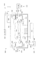
化学気相堆積法やエッチングなどの半導体基板製作プロセスに使用される例示的な従来のプロセスチャンバ20が図1に図示されている。概して、プロセスチャンバ20は、プロセスゾーン40を取り囲む天井28と、側壁32と、底壁36とを含むエンクロージャ壁24を備える。チャンバ20はまた、プロセスゾーン40を中心にエンクロージャ壁24の少なくとも一部を裏打ちするライナー44を備えてもよい。プロセスガスは、プロセスガス源52およびガスディストリビューター56を含むガスサプライ48を介してチャンバ20に導入される。ガスディストリビューター56は、1つ以上のガス流バルブ64を有する1つ以上の導管60と、基板26を受け取るための基板受け取り表面102を有する基板サポート100の周辺の1つ以上のガス入り口68とを備えてもよい。あるいはまた、ガスディストリビューターは、天井28からプロセスゾーン40にプロセスガスを分布させるシャワーヘッドガスディストリビューター(図示せず)を備えてもよい。使用済みプロセスガスおよびエッチャント副生成物は、プロセスゾーン40から使用済みプロセスガスを受け取るポンピングチャネル76と、チャンバ20におけるプロセスガスの圧力をコントロールするためのスロットルバルブ80と、1つ以上の排気ポンプ84とを含んでもよい排気装置72を介してチャンバ20から排気される。
An exemplary
例えばエンクロージャ壁24と、ライナー44と、基板サポート100と、ガスサプライ48と、ガスエナジャイザー92と、ガス排気装置72と、基板トランスポート96のうちの1つ以上の少なくとも一部を含むチャンバコンポーネント22は一般的に、腐食性ハロゲン含有種に暴露される。チャンバコンポーネントをプラズマ洗浄するために一般的に使用されるガス混合物は特に腐食性である。
For example,
あるチャンバコンポーネント22は、プロセスチャンバ20のコンポーネント22の機能に必要とされる形状にアルミニウムまたはアルミニウム合金を形作ることによって、アルミニウム材料から製作される。例えば、アルミニウムコンポーネント22は、平面部分、曲線部分、出っ張り、フランジ、ホール、および他の幾何学的配列を有する形状を備えることができる。コンポーネント22は、鍛造、機械加工、成形、押し出し、あるいはこれらまたは他の製造プロセスの組み合わせを含む多数のプロセスによって形成可能である。コンポーネント22のアルミニウムまたはアルミニウム合金は、コンポーネント22の製造的かつ機能的要件にしたがって選択される。例えば、コンポーネント22の形状およびサイズは、アルミニウムまたはアルミニウム合金の所望の材料特性を判断可能である。
One
一変形例において、コンポーネント22のアルミニウムまたはアルミニウム合金は、LP(商標)アルミニウム合金と称されるアルミニウム合金であり、これはカリフォルニア州、サンタモニカにあるアプライドマテリアルズ社に譲渡された、Lin氏らへの米国特許出願第2003/0150530号に説明されているアルミニウム合金である。LP(商標)はアプライドマテリアルズ社の商標である。LP(商標)アルミニウム合金は、より高品質の陽極アルミニウムコーティングにつながるために好都合なものでありうる。LP(商標)アルミニウム合金において、移動性および非移動性不純物の濃度は具体的な範囲内にあるようにコントロールされる。特に、このような合金は以下の組成物を重量%で有するべきである:約3.5%〜約4.0%のマグネシウム濃度、0.03%未満のシリコン濃度、0.03%未満の鉄濃度、約0.02%〜約0.07%の銅濃度、約0.005%〜約0.015%のマンガン濃度、約0.08%〜約0.16%の亜鉛濃度、約0.02%〜約0.07%のクロム濃度、および0.01%未満のチタン濃度であり、他の単一の不純物は各々約0.03%を超えず、また他の全不純物は約0.1%を超えない。
In one variation, the aluminum or aluminum alloy of
加えて、LP(商標)アルミニウム合金は、移動性不純物から形成された微粒子に関して特定の仕様を満たすために必要とされる。不純物化合物の粒子状集塊のうち、全粒子の少なくとも95%は5μm未満のサイズでなければならない。粒子の5%は5μm〜20μmに及ぶサイズであってもよい。最終的に、粒子の最大0.1%は20μmより大きくてもよく、40μmより大きな粒子はない。 In addition, LP ™ aluminum alloy is required to meet specific specifications for particulates formed from mobile impurities. Of the particulate agglomerates of impurity compounds, at least 95% of all particles must be less than 5 μm in size. 5% of the particles may be of a size ranging from 5 μm to 20 μm. Finally, up to 0.1% of the particles may be larger than 20 μm and no particles are larger than 40 μm.
別の変形例において、コンポーネント22のアルミニウムまたはアルミニウム合金は、例えば6061アルミニウム合金などのアルミニウム−マグネシウム−シリコン合金であってもよく、これは普通の、容易に入手可能な材料であるために好都合でありうる。さらに他の形態において、コンポーネント22のアルミニウムまたはアルミニウム合金は、5000シリーズ(5xxx)アルミニウム合金(例えば5005、5050、5052、5083、5086、5144、5144、5357、5447、5454、5456または5457アルミニウム合金)などのアルミニウム−マグネシウム合金であってもよい。
In another variation, the aluminum or aluminum alloy of
チャンバ20の腐食環境に暴露されると、アルミニウムコンポーネント22は、コンポーネント22の表面から剥がれ落ちたり、これに間隙を作成したりすることがある化合物を生成する、塩素、フッ素および臭素などのハロゲン類との反応に影響を受けやすい。このことによってコンポーネント22は侵食し、またチャンバ20の粒子状汚染の源となる。
When exposed to the corrosive environment of the
一変形例において、コンポーネント22は保護されて、チャンバ20の汚染はコンポーネント22の表面に保護コーティングを形成することによって最小限にされる。図2A〜図2Cは、製作中のアルミニウムコンポーネント22の断面側面図を図示しており、図3は、アルミニウムコンポーネント22上に保護コーティングを形成するプロセスを図示するフローチャートである。図2A〜図2Cおよび図3を参照すると、保護コーティングを受け取るコンポーネント22の表面116は保護コーティングを受け取るように処置されてもよい(ステップ300)。コーティングを形成する前の表面116の処置は、製作のスピードおよび簡単さと、最終的な保護コーティングの品質とに寄与することがある。
In one variation, the
一変形例において、コンポーネント22の表面116の処置は、表面116にビーズ粒子を推進するビーズブラスティングプロセスを実行することによって表面116を粗くするステップを含む。ビーズブラスティングプロセスは、アルミニウムコンポーネント22の表面116の適切な表面粗さおよび他の特色を形成する。例えば、ビーズブラスティングは、コンポーネント表面116の特徴の過度に鋭いエッジおよびコーナーを侵食することによって、潜在的なストレスを導く特徴を下地層に供することのない表面116を生成することができる。ビーズブラスティングプロセスはまた、表面116に対する材料の接着を改良するために、コンポーネント表面116の部分をテクスチャ化することができる。例えば、堆積された材料は、完全に平滑な表面と比較して、コントロールされたテクスチャを具備する表面により良好に接着する。
In one variation, treating the
ビーズブラスティングプロセスにおいて、硬質ビーズ粒子のストリームが、ビーズ粒子を侵食させ、かつ表面116から材料を除去するのに十分高い圧力に加圧されるガスによってコンポーネント22の表面116に向かって推進される。例えば、適切な圧力は約20psi〜約110psiであってもよい。ビーズ粒子は望ましくは、表面116よりも高い硬度を有する材料を備える。例えば、グリット粒子は、酸化アルミニウム、ガーネット、酸化シリコン、シリコンカーバイド、ガラス、シリカ、硬質プラスチックまたはこれらの混合物を備えることができる。ビーズ粒子のサイズはまた、表面116へのビーズブラスティングプロセスによって作成された特徴のサイズに影響を与えるように選択可能である。例えば、ビーズ粒子は約100〜約200のメッシュサイズを有することができる。コンポーネント表面116に対するビーズ粒子の入射角度および、ビーズ粒子のソースからコンポーネント22までビーズ粒子が進んだスタンドオフ距離はまた、表面116の所望の粗さを提供するように選択可能である。例えば、コンポーネント表面116に対するビーズ粒子の入射角度は約30°〜約60°であってもよく、またスタンドオフ距離は約7cm〜約32cmであってもよい。一変形例において、コンポーネント22の表面116は、例えば約100マイクロインチ〜約200マイクロインチの粗さ平均を有するように粗くされる。
In the bead blasting process, a stream of hard bead particles is propelled toward the
コンポーネント22の表面116の処置はまた、表面116を洗浄して、不純物を除去しかつ粒子を解き放つステップを含んでもよい。洗浄プロセスはまた、鍛造や機械加工プロセスによるオイルや冷却剤、あるいは砂または成形プロセスからの他の材料などの、コンポーネント22の製作から残ることがある化学物質や材料を除去可能である。洗浄プロセスはまたコンポーネント22の表面116を化学的に研磨してもよい。例えば、洗浄プロセスは外部の材料層をコンポーネント22から除去可能である。このことは、コンポーネント22の表面上に形成されていた可能性のある望ましくない酸化物および他の材料を除去することがある。一変形例において、コンポーネント22の表面116は、酸性溶液、有機溶媒、アルカリ溶液、水、脱イオン水またはこれらの混合物を備える溶液に含浸される。例えば、酸性溶液はシュウ酸、リン酸、硝酸、硫酸またはこれらの混合物を備えてもよい。有機溶媒はアセトン、イソプロピルアルコールまたはこれらの混合物を備えてもよい。アルカリ溶液は水酸化ナトリウム、水酸化カリウムまたはこれらの混合物を備えてもよい。加えて、表面は、異なる組成物および濃度を備える複数の異なる溶液に含浸されてもよい。
Treatment of the
例えば、一変形例において、コンポーネント22の表面116は、(i)有機溶媒を備える溶液に表面116を含浸すること、(ii)表面116を水でリンスすること、(iii)酸を備える溶液に表面116を含浸すること、および(iv)表面116を脱イオン水でリンスすることによって洗浄されてもよい。ステップ(iii)において、溶液は、例えば約15℃〜約90度の温度で約5〜約50重量%の硫酸を備えてもよく、また表面116は約1分〜約30分間含浸されてもよい。別の実施例において、コンポーネント22の表面116は、(i)硝酸を備える溶液に表面116を含浸すること、(ii)表面116を脱イオン水でリンスすること、(iii)水酸化ナトリウムを備える溶液に表面116を含浸すること、(iv)表面116を脱イオン水でリンスすること、(v)アセトンを備える溶液に表面116を浸すこと、および(vi)イソプロピルアルコールを備える溶液に表面116を含浸することによって洗浄されてもよい。また、超音波処理などの他の洗浄方法も使用可能である。
For example, in one variation, the
アルミニウムコンポーネント22の表面116が処置された後、表面116は、図2Bに図示されるように、陽極酸化アルミニウム層120を作成するために陽極化される(ステップ302)。陽極化プロセスの一変形例において、コンポーネント22は、例えば図4に示されるように、電解セル148において陽極150の役割をする。図2Bおよび図4を参照すると、電解セル148は陽極溶液164を保持するタンク168と、電圧源152とコンポーネント22とを備える。コンポーネント22は電圧源152の正端子156に接続され、また電圧源152の負端子160に接続されたタンク168は陰極154の役割をする。コンポーネント22の表面116は、例えばイオン含有酸素を有する水成電解質を備える陽極溶液164に含浸される。電圧源152から陰極154および陽極150へのバイアス電圧の印加はコンポーネント22の表面116上に正電荷を築き上げ、溶液中の負帯電された電解種を表面116に引き付ける。負帯電種中の酸素はコンポーネントの表面116のアルミニウムと結びついて、第1の陽極酸化アルミニウム層120を形成する。
After the
陽極溶液164の濃度および組成、電圧源152によって供給された電圧および電流、またプロセスが行われる温度などの陽極化条件は、所望の厚さおよび構造的特性を有する陽極酸化アルミニウム層120を提供するように選択されてもよい。適切な陽極溶液164は、例えば硫酸、クロム酸、シュウ酸、リン酸、水またはこれらの混合物を備えることが可能である。異なる陽極溶液組成および他の電解液などの他の適切な陽極化条件も使用可能である。例えば、一変形例において、アルミニウムコンポーネント22は、15重量%の硫酸と、1重量%のクロム酸と水とを備える陽極溶液164において陽極化される。アルミニウムコンポーネント22は約15℃〜約40度の温度で約1分〜約30分間陽極化される。陰極154および陽極150間に印加された電圧は約10V〜約100Vであり、電流は約0.5amps〜約5ampsに制限される。
The anodization conditions, such as the concentration and composition of the
陽極酸化アルミニウム層120の表面124は、概して、欠陥、ひび、亀裂、孔隙、およびその他の平面性からのずれなどの表面特徴部128を有する。これらの表面特徴部128は、普通、陽極酸化アルミニウム層の表面上に見られる。表面特徴部128は、陽極化プロセスによって作成された層に固有であり、また下地アルミニウムコンポーネント22およびその表面116上の不純物などの他の原因によってもたらされる。しかしながら、表面特徴部128の態様は、陽極酸化アルミニウム層120が下地アルミニウムコンポーネント22を提供することができるという保護に関しては望ましくない。例えば、陽極酸化アルミニウム層120に延びる表面特徴部128によって、基板26の処理中にプロセスチャンバ20にあるガスおよびプラズマなどの侵食剤は酸化アルミニウム層120の内側にアクセスし、したがって下地アルミニウムコンポーネント22を保護している層120の厚さを削減することがある。
表面特徴部128の望ましくない効果を削減または排除するために、別の酸化アルミニウム層132が、物理気相堆積法(PVD)やスパッタリングプロセスを使用して陽極酸化アルミニウム層120上に形成される(ステップ304)。スパッタ酸化アルミニウム層132は、図2Cに図示されるように表面特徴部128をふさいで除去し、コンポーネントの暴露表面上にシーリング剤層を形成する。
In order to reduce or eliminate the undesirable effects of the surface features 128, another
第2の酸化アルミニウム層132を堆積させるのに適した例示的プロセスチャンバが図5に図示される。プロセスチャンバ506は物理気相堆積つまりPVDチャンバとも呼ばれるスパッタリング堆積チャンバを備えており、これは、タンタル、窒化タンタル、チタン、窒化チタン、銅、タングステン、窒化タングステンおよびアルミニウムのうちの1つ以上などの材料を、基板504上にスパッタリング堆積させることができる。ここで、基板504は陽極酸化アルミニウム層120を具備するアルミニウムコンポーネント22である。チャンバ506は、プロセスゾーン509を取り囲みかつ側壁564と底壁566と天井568とを含むエンクロージャ壁518を備える。他のチャンバ壁は、スパッタリング環境からエンクロージャ壁518を遮断する1つ以上のシールド520を含むことができる。
An exemplary process chamber suitable for depositing the second
チャンバ506は、基板504をスパッタリング堆積チャンバ506においてサポートするための基板サポート514を備える。基板サポート514は電気的に浮遊していてもよく、あるいはRF電源などの電源572によってバイアスされる電極570を備えてもよい。基板サポート514はまた、基板504がない場合にサポート514の上部表面534を保護することができる可動シャッターディスク533を備えることができる。動作において、基板504はチャンバ506の側壁564における基板ローディング入口(図示せず)を介してチャンバ106に導入され、サポート514上に置かれる。サポート514はサポートリフトベローズによって持ち上げられたり下げられたりすることができ、リフトフィンガアセンブリ(図示せず)は、チャンバ506に対する基板504のトランスポート中にサポート上514上に基板504を持ち上げたり下げたりするために使用可能である。
The
スパッタリングガスなどのプロセスガスが、各々が質量流コントローラなどのガス流コントロールバルブ578を有する導管576を供与して設定流量のガスを流す1つ以上のガス源574を備えるプロセスガスサプライを含むガス送出システム512を介してチャンバ506に導入される。導管576は、ガスが混合されて所望のプロセスガス組成を形成する混合マニフォルド(図示せず)にガスを供与することができる。混合マニフォルドは、チャンバ506において1つ以上のガス出口582を有するガスディストリビューター580を供与する。
Gas delivery including a process gas supply comprising one or
プロセスガスは、アルゴンやキセノンなどの非反応性ガスを備えてもよく、これはターゲットにエネルギ的に影響を与え、かつこれから材料をスパッタリングすることができる。プロセスガスはまた、酸素含有ガスおよび窒素含有ガスのうちの1つ以上などの反応性ガスを備えてもよく、これらはスパッタ材料と反応して、酸化アルミニウムなどの層を基板504上に形成することができる。使用済みプロセスガスおよび副生成物は、使用済みプロセスガスを受け取り、かつチャンバ506においてガスの圧力をコントロールするためのスロットルバルブ588がある排気導管586に使用済みガスを渡す1つ以上の排気ポート584を含む排気装置523を介してチャンバ506から排気される。排気導管586は1つ以上の排気ポンプ590を供与する。一般的に、チャンバ506のスパッタリングガスの圧力はサブ大気レベルに設定される。
The process gas may comprise a non-reactive gas such as argon or xenon, which energetically affects the target and from which material can be sputtered. The process gas may also comprise a reactive gas, such as one or more of an oxygen-containing gas and a nitrogen-containing gas, which reacts with the sputter material to form a layer such as aluminum oxide on the
スパッタリングチャンバ506はさらに、基板504の表面505に面しており、かつアルミニウムなどの、基板504上にスパッタリングされる材料を備えるスパッタリングターゲット524を備える。ターゲット524は環状絶縁リング532によってチャンバ506から電気的に隔離されており、また電源592に接続される。スパッタリングチャンバ506はまた、チャンバ506の壁518をスパッタ材料から保護するためのシールド520を有する。一変形例において、電源592、ターゲット524およびシールド520のうちの1つ以上は、スパッタリングガスを付勢してターゲット524から材料をスパッタリングすることができるガスエナジャイザー516として動作する。電源592はバイアス電圧をシールド520に対するターゲット524に印加する。印加された電圧からチャンバ506に発生された電界はスパッタリングガスにエネルギを与えて、ターゲット524から基板504に材料をスパッタリングするためにターゲット524にエネルギ的に影響を与え、かつこれに衝突するプラズマを形成する。電極570およびサポート電極電源572を有するサポート514はまた、ターゲット524から基板504に向かってスパッタリングされたイオン化材料を付勢および加速させることによってガスエナジャイザー516の一部として動作してもよい。更にまた、電源592によって電源投入され、かつチャンバ506内に位置決めされて、高められエネルギが与えられたガス特性(改良された付勢ガス密度など)を提供するガスエネルギ付与コイル535が提供される。ガスエネルギ付与コイル535は、シールド520や、チャンバ506の他の壁に取り付けられるコイルサポート537によってサポート可能である。
The sputtering
チャンバ506は、チャンバ506において基板504を処理するようにチャンバ506のコンポーネントを動作させる命令セットを有するプログラムコードを備えるコントローラ594によってコントロール可能である。例えば、コントローラ594は、基板サポート514と、チャンバ506において基板504を位置決めするための基板トランスポートのうちの1つ以上を動作させる基板位置決め命令セットと、チャンバ506へのスパッタリングガスの流れを設定するように流れコントロールバルブ578を動作させるガス流コントロール命令セットと、チャンバ506の圧力を維持するように排気スロットルバルブ588を動作させるガス圧力コントロール命令セットと、ガス付勢電力レベルを設定するようにガスエナジャイザー516を動作させるガスエナジャイザーコントロール命令セットと、チャンバ506のプロセスを監視するためのプロセス監視命令セットとを備えることができる。
一変形例において、スパッタリングチャンバ506は、非反応性ガス、例えばアルゴンを備えるスパッタリングガスと酸素含有ガスとを導入して、電圧をアルミニウムターゲット524に印加することによって、スパッタ酸化アルミニウム層132を形成するために使用される。堆積中に、ターゲット524からのアルミニウムイオンは酸素含有ガスと反応して、酸化アルミニウム層132を基板504上に形成する。
In one variation, the sputtering
陽極酸化アルミニウム層120およびスパッタ酸化アルミニウム層132の厚さは、コーティングを処理する長さおよびコストと、下地アルミニウムコンポーネント22から薄い層に裂くという、過度に厚いコーティングの傾向などの望ましくない態様を最小限にしつつ、保護コーティングの有効性を最大限にするように選択される。一変形例において、下地アルミニウムコンポーネントが標準6061アルミニウム合金を備えている場合、陽極酸化アルミニウム層120の厚さは約15〜約35μm、例えば約25μm(およそ1mil)であり、またスパッタ酸化アルミニウム層132の厚さは約2μm〜約5μmである。別の変形例において、下地アルミニウムコンポーネントがLP(商標)アルミニウム合金を備える場合、陽極酸化アルミニウム層120の厚さは同じであるが、スパッタ酸化アルミニウム層132の厚さは約1μm〜約2μmと、より薄くなる。
The thickness of the anodized
酸化アルミニウム層132を形成するための方法において、PVDやスパッタリングプロセスは、例えば化学気相堆積法(CVD)およびプラズマスプレープロセスなどの、酸化アルミニウム層を堆積させるための他のプロセスと比較して好ましい。PVDプロセスは非常に低い孔隙率で高密度のコンフォーマルな酸化アルミニウム層132を堆積させるのに対して、CDVプロセスは、高い孔隙率、それゆえに低い耐食特性を有する酸化アルミニウム層を堆積させるために、スパッタ酸化アルミニウム層132はCVD酸化アルミニウム層よりも好ましいことが観察されている。
In the method for forming the
その高密度および低孔隙率によって特徴付けられるスパッタ酸化アルミニウム層132は下地陽極酸化アルミニウム層120とその下のアルミニウムコンポーネント22とを腐食性ガスから効果的に保護し、またアルミニウムコンポーネント22の不純物がアルミニウムコンポーネント22からチャンバ20に拡散することを防止する。したがって、2層保護コーティングはコンポーネント20を、腐食性ガスに対してより影響を受けにくくし、これによってコンポーネントの耐久性と寿命を改善し、また不純物がコンポーネント20から逃げるのを防止することによって、チャンバ20の汚染を実質的に削減することができる。
The sputtered
本発明の例示的実施形態が示されかつ説明されたが、当業者は、本発明を組み込み、かつ本発明の範囲内にある他の実施形態を考案してもよい。例えば、下地構造は、当業者には明らかであろうが、具体的に言及されたもの以外にチャンバコンポーネント22の部分を形成してもよい。さらにまた、下方、上方、底部、上部、上、下、第1および第2という用語と、他の相対的または位置的用語は図面の例示的実施形態に関して示されており、また互換性がある。したがって、添付の請求項は、本発明を図示するために、本明細書に説明された好ましい形態、材料または空間的配列の説明に制限されるべきではない。
While exemplary embodiments of the present invention have been shown and described, those skilled in the art may devise other embodiments that incorporate and are within the scope of the present invention. For example, the underlying structure will be apparent to those skilled in the art, but may form part of the
20…プロセスチャンバ、22…チャンバコンポーネント、24…エンクロージャ壁、26…基板、28…天井、32…側壁、36…底壁、40…プロセスゾーン、44…ライナー、48…ガスサプライ、52…プロセスガス源、56…ガスディストリビューター、60…導管、64…ガス流バルブ、68…ガス入口、72…排気装置、76…ポンピングチャネル、80…スロットルバルブ、84…排気ポンプ、92…ガスエナジャイザー、96…基板トランスポート、100…基板サポート、102…基板受け取り表面、106…チャンバ、116…コンポーネントの表面、120…陽極酸化アルミニウム層、124…陽極酸化アルミニウム層の表面、128…表面特徴部、132…酸化アルミニウム層、148…電解セル、150…陽極、152…電圧源、154…陰極、156…正端子、160…負端子、164…陽極溶液、168…タンク、300…ステップ、302…ステップ、304…ステップ、504…基板、505…表面、506…プロセスチャンバ、509…プロセスゾーン、512…ガス送出システム、514…基板サポート、516…ガスエナジャイザー、518…チャンバ壁、520…シールド、514…基板サポート、523…排気装置、524…スパッタリングターゲット、532…絶縁リング、533…可動シャッターディスク、534…上部表面、535…ガスエネルギ付与コイル、537…コイルサポート、564…側壁、566…底壁、568…天井、570…電極、572…電極電源、574…ガス源、576…導管、578…ガス流コントロールバルブ、580…ガスディストリビューター、582…ガス出口、584…排気ポート、586…排気導管、588…スロットルバルブ、590…排気ポンプ、592…電源、594…コントローラ。
DESCRIPTION OF
Claims (24)
(a)粗さが約100〜約200マイクロインチのビーズブラスティングされた粗い面を有するアルミニウムチャンバコンポーネント本体と、
(b)前記アルミニウムチャンバコンポーネント本体の前記粗い面に形成された、厚さ約15μm〜約35μmの陽極酸化アルミニウム層と、
(c)前記陽極酸化アルミニウム層の上の厚さ約2μm〜約5μmの酸化アルミニウムからなるスパッタリングされた酸化アルミニウム層と、を備える、アルミニウムチャンバコンポーネント。 A corrosion resistant aluminum chamber component for a substrate process chamber,
(A) an aluminum chamber component body having a bead blasted rough surface with a roughness of about 100 to about 200 microinches ;
(B) an anodized aluminum layer having a thickness of about 15 μm to about 35 μm formed on the rough surface of the aluminum chamber component body;
(C) an aluminum chamber component comprising a sputtered aluminum oxide layer comprising aluminum oxide having a thickness of about 2 μm to about 5 μm on the anodized aluminum layer.
(a)エンクロージャ壁の一部、ライナー、基板サポート、ガスサプライ、ガスエナジャイザー、ガス排気装置、プロセスチャンバの基板トランスポートを、少なくとも備えるアルミニウムチャンバコンポーネントを提供するステップと、
(b)ビーズブラスティングによって前記アルミニウムチャンバコンポーネントの表面を粗くして粗さを約100〜約200マイクロインチとするステップと、
(c)陽極酸化アルミニウム層を形成するために前記アルミニウムチャンバコンポーネントの前記表面を陽極酸化するステップと、
(d)前記陽極酸化アルミニウム層およびスパッタリングされた酸化アルミニウム層が前記アルミニウムチャンバコンポーネントを腐食性ガスから保護することができるように、前記陽極酸化アルミニウム層上に厚さが約2μm〜約5μmの酸化アルミニウムからなるスパッタリングされた酸化アルミニウム層をスパッタリングコーティングするステップと、
を備える方法。 A method of manufacturing a corrosion resistant aluminum chamber component having a surface comprising:
(A) providing an aluminum chamber component comprising at least a portion of an enclosure wall, a liner, a substrate support, a gas supply, a gas energizer, a gas exhaust device, a substrate transport of a process chamber;
(B) roughening the surface of the aluminum chamber component by bead blasting to a roughness of about 100 to about 200 microinches ;
(C) a said surface of the aluminum chamber component to form an anodic aluminum oxide layer and the step of anodizing,
(D) Oxidation having a thickness of about 2 μm to about 5 μm on the anodized aluminum layer so that the anodized aluminum layer and the sputtered aluminum oxide layer can protect the aluminum chamber components from corrosive gases. Sputter coating a sputtered aluminum oxide layer of aluminum;
A method comprising:
(i)アルミニウムを備えるターゲットに面するプロセスゾーンに、前記アルミニウムチャンバコンポーネントの面に形成された陽極酸化アルミニウム層を置く工程と、
(ii)アルゴンを備えるスパッタリングガスと酸素含有ガスとを前記プロセスゾーンに導入する工程と、
(iii)電圧をアルミニウムターゲットに印加する工程と、
(iv)前記スパッタリングガスを前記プロセスゾーンから排気する工程と、
を備える、請求項4に記載の方法。 Step (d)
(I) placing an anodized aluminum layer formed on the surface of the aluminum chamber component in a process zone facing a target comprising aluminum;
(Ii) introducing a sputtering gas comprising argon and an oxygen-containing gas into the process zone;
(Iii) applying a voltage to the aluminum target;
(Iv) exhausting the sputtering gas from the process zone;
The method of claim 4 comprising:
(i)硫酸、クロム酸、シュウ酸、リン酸、水またはこれらの混合物のうちの1つ以上を備える陽極酸性溶液に前記アルミニウムチャンバコンポーネントの前記表面を浸す工程と、
(ii)電圧を前記アルミニウムチャンバコンポーネントに印加する工程と、
によって前記アルミニウムチャンバコンポーネントの前記表面を陽極酸化するステップを備える、請求項4に記載の方法。 Step (c)
(I) immersing the surface of the aluminum chamber component in an anodic acid solution comprising one or more of sulfuric acid, chromic acid, oxalic acid, phosphoric acid, water or mixtures thereof;
(Ii) applying a voltage to the aluminum chamber component;
5. The method of claim 4, comprising anodizing the surface of the aluminum chamber component by:
(a)エンクロージャ壁の一部、ライナー、基板サポート、ガスサプライ、ガスエナジャイザー、ガス排気装置、プロセスチャンバの基板トランスポートを、少なくとも備えるアルミニウムチャンバコンポーネントを提供するステップと、
(b)ビーズブラスティングによって前記アルミニウムチャンバコンポーネントの表面を粗くして粗さを約100〜約200マイクロインチとするステップと、
(c)表面特徴部を有する、厚さが約15μm〜35μmの陽極酸化アルミニウム層を形成するために前記アルミニウムチャンバコンポーネントの前記表面を陽極酸化するステップと、
(d)(i)アルミニウムを備えるターゲットに面するプロセスゾーンに、前記アルミニウムチャンバコンポーネントの面に形成された陽極酸化アルミニウム層を置く工程と、
(ii)アルゴンを備えるスパッタリングガスと酸素含有ガスとを前記プロセスゾーンに導入する工程と、
(iii)電圧をアルミニウムターゲットに印加する工程と、
(iv)前記スパッタリングガスを前記プロセスゾーンから排気する工程と、
によって、前記陽極酸化アルミニウム層上で、酸化アルミニウムからなる厚さ約2μm〜約5μmのスパッタリングされた酸化アルミニウム層をスパッタリングコーティングして前記表面特徴部をふさぐステップと、
を備え、
前記陽極酸化アルミニウム層及び酸化アルミニウムのスパッタリング層が、前記アルミニウムチャンバコンポーネントを腐食性ガスから保護する方法。 A method of manufacturing a corrosion resistant aluminum chamber component having a surface comprising:
(A) providing an aluminum chamber component comprising at least a portion of an enclosure wall, a liner, a substrate support, a gas supply, a gas energizer, a gas exhaust device, a substrate transport of a process chamber;
(B) roughening the surface of the aluminum chamber component by bead blasting to a roughness of about 100 to about 200 microinches ;
(C) anodizing the surface of the aluminum chamber component to form an anodized aluminum layer having a surface feature and having a thickness of about 15 μm to 35 μm;
(D) (i) placing an anodized aluminum layer formed on the surface of the aluminum chamber component in a process zone facing a target comprising aluminum;
(Ii) introducing a sputtering gas comprising argon and an oxygen-containing gas into the process zone;
(Iii) applying a voltage to the aluminum target;
(Iv) exhausting the sputtering gas from the process zone;
Sputter-coating a sputtered aluminum oxide layer of about 2 μm to about 5 μm thick of aluminum oxide on the anodized aluminum layer to cover the surface features;
With
The method wherein the anodized aluminum layer and the aluminum oxide sputtering layer protect the aluminum chamber components from corrosive gases.
(a)アルミニウムからなり、内側及び外側の表面を有する基板プロセスチャンバ壁を提供するステップと、
(b)ビーズブラスティングによって前記チャンバ壁の内側表面を粗くして粗さを約100〜約200マイクロインチとするステップと、
(c)前記チャンバ壁の内側表面を陽極酸化して、表面特徴部を有する陽極酸化アルミニウム層を形成するステップと、
(d)前記陽極酸化アルミニウム層上に、酸化アルミニウムからなる厚さ約2μm〜約5μmのスパッタリングされた酸化アルミニウム層をスパッタリングコーティングして前記表面特徴部をふさぐステップと、
を備え、前記陽極酸化アルミニウム層及び酸化アルミニウムのスパッタリング層が、前記アルミニウムチャンバコンポーネントを腐食性ガスから保護する方法。 A method for providing a corrosion resistant coating on a surface of a substrate process chamber wall comprising:
(A) providing a substrate process chamber wall made of aluminum and having inner and outer surfaces;
(B) roughening the inner surface of the chamber wall by bead blasting to a roughness of about 100 to about 200 microinches ;
(C) anodizing the inner surface of the chamber wall to form an anodized aluminum layer having surface features ;
(D) Sputter-coating a sputtered aluminum oxide layer having a thickness of about 2 μm to about 5 μm made of aluminum oxide on the anodized aluminum layer to close the surface feature;
And wherein the anodized aluminum layer and the aluminum oxide sputtering layer protect the aluminum chamber components from corrosive gases.
(b)前記基板プロセスチャンバ壁の内側表面の粗い面上に形成された、厚さが約15μm〜約35μmの陽極酸化アルミニウム層と、
(c)前記陽極酸化アルミニウム層上の酸化アルミニウムからなる、厚さが約1μm〜約5μmのスパッタリング酸化アルミニウム層と、
を備えた、耐食性基板プロセスチャンバコンポーネント。 (A) a substrate process chamber wall made of aluminum and having inner and outer surfaces, wherein the inner surface has a bead blasted rough surface, the roughness being from about 100 to about 200 microinches ; ,
(B) an anodized aluminum layer having a thickness of about 15 μm to about 35 μm formed on a rough surface of the inner surface of the substrate process chamber wall;
(C) a sputtered aluminum oxide layer having a thickness of about 1 μm to about 5 μm, comprising aluminum oxide on the anodized aluminum layer;
A corrosion resistant substrate process chamber component comprising:
(a)エンクロージャ壁の一部、ライナー、基板サポート、ガスサプライ、ガスエナジャイザー、ガス排気装置、プロセスチャンバの基板トランスポートを、少なくとも備えるアルミニウムチャンバコンポーネントを形成するステップと、
(b)前記アルミニウムチャンバコンポーネントの表面をビーズブラスティングして平均の粗さを約100〜約200マイクロインチとするステップと、
(c)前記アルミニウムチャンバコンポーネントのビーズブラスティングした表面を洗浄するステップと、
(d)ビーズブラスティングして洗浄した前記アルミニウムチャンバコンポーネントを陽極酸化して、厚さ約15μm〜約35μmの陽極酸化アルミニウム層を形成するステップと、ここで、陽極酸化は、
(i)前記アルミニウムチャンバコンポーネントのビーズブラスティングした表面を硫酸、クロム酸、シュウ酸、リン酸、水またはこれらの混合物のうちの1つ以上を備える陽極酸性溶液に含浸する工程と、
(ii)前記陽極酸性溶液に含浸しながら電圧を前記アルミニウムチャンバコンポーネントに印加する工程と、
を含み、
(e)(i)アルミニウムを備えるターゲットに面するプロセスゾーンに、前記ビードブラスティングした表面に堆積された陽極酸化された酸化アルミニウム層を置く工程と、
(ii)アルゴンを備えるスパッタリングガスと酸素含有ガスとを前記プロセスゾーンに導入する工程と、
(iii)電圧をアルミニウムターゲットに印加する工程と、
(iv)前記スパッタリングガスを前記プロセスゾーンから排気する工程と、
によって、酸化アルミニウムからなる厚さ約2μm〜約5μmのスパッタリングされた酸化アルミニウム層をスパッタリングコーティングして前記陽極酸化アルミニウム層の表面特徴部をふさぐステップと、
を含む方法。 A method of manufacturing an aluminum chamber component having a corrosion resistant surface comprising:
(A) forming an aluminum chamber component comprising at least a portion of an enclosure wall, a liner, a substrate support, a gas supply, a gas energizer, a gas exhaust device, a substrate transport of the process chamber;
(B) bead blasting the surface of the aluminum chamber component to an average roughness of about 100 to about 200 microinches ;
(C) cleaning the bead-blasted surface of the aluminum chamber component;
(D) anodizing the aluminum chamber components cleaned by bead blasting to form an anodized aluminum layer having a thickness of about 15 μm to about 35 μm, wherein anodizing comprises:
(I) impregnating the bead-blasted surface of the aluminum chamber component with an anodic acid solution comprising one or more of sulfuric acid, chromic acid, oxalic acid, phosphoric acid, water or mixtures thereof;
(Ii) applying a voltage to the aluminum chamber component while impregnating the anodic acid solution;
Including
(E) (i) placing an anodized aluminum oxide layer deposited on the bead blasted surface in a process zone facing the target comprising aluminum ;
(Ii) introducing a sputtering gas comprising argon and an oxygen-containing gas into the process zone;
(Iii) applying a voltage to the aluminum target;
(Iv) exhausting the sputtering gas from the process zone;
Sputter-coating a sputtered aluminum oxide layer having a thickness of about 2 μm to about 5 μm comprising aluminum oxide to cover the surface features of the anodized aluminum layer;
Including methods.
Applications Claiming Priority (2)
| Application Number | Priority Date | Filing Date | Title |
|---|---|---|---|
| US11/037,633 US7732056B2 (en) | 2005-01-18 | 2005-01-18 | Corrosion-resistant aluminum component having multi-layer coating |
| US11/037,633 | 2005-01-18 |
Publications (3)
| Publication Number | Publication Date |
|---|---|
| JP2006241589A JP2006241589A (en) | 2006-09-14 |
| JP2006241589A5 JP2006241589A5 (en) | 2011-07-21 |
| JP4881015B2 true JP4881015B2 (en) | 2012-02-22 |
Family
ID=36684247
Family Applications (1)
| Application Number | Title | Priority Date | Filing Date |
|---|---|---|---|
| JP2006010308A Expired - Fee Related JP4881015B2 (en) | 2005-01-18 | 2006-01-18 | Corrosion resistant aluminum component with multilayer coating |
Country Status (4)
| Country | Link |
|---|---|
| US (1) | US7732056B2 (en) |
| JP (1) | JP4881015B2 (en) |
| CN (1) | CN2935467Y (en) |
| TW (1) | TWM310107U (en) |
Families Citing this family (46)
| Publication number | Priority date | Publication date | Assignee | Title |
|---|---|---|---|---|
| US8372205B2 (en) * | 2003-05-09 | 2013-02-12 | Applied Materials, Inc. | Reducing electrostatic charge by roughening the susceptor |
| US20040221959A1 (en) * | 2003-05-09 | 2004-11-11 | Applied Materials, Inc. | Anodized substrate support |
| US20090194233A1 (en) * | 2005-06-23 | 2009-08-06 | Tokyo Electron Limited | Component for semicondutor processing apparatus and manufacturing method thereof |
| DE102005058324A1 (en) * | 2005-12-07 | 2007-06-14 | Mtu Aero Engines Gmbh | Method for producing an inlet lining |
| US8173228B2 (en) * | 2006-01-27 | 2012-05-08 | Applied Materials, Inc. | Particle reduction on surfaces of chemical vapor deposition processing apparatus |
| US8282807B2 (en) * | 2006-12-28 | 2012-10-09 | National University Corporation Tohoku University | Metal member having a metal oxide film and method of manufacturing the same |
| JP5162148B2 (en) * | 2007-03-26 | 2013-03-13 | 株式会社アルバック | Composite and production method thereof |
| JP4774014B2 (en) * | 2007-05-21 | 2011-09-14 | 株式会社神戸製鋼所 | Al or Al alloy |
| DE102010060143A1 (en) * | 2009-11-05 | 2011-06-09 | Oerlikon Solar Ag, Trübbach | Method for producing vacuum-processing chamber that is utilized in e.g. physical vapor deposition, involves defining volume of vacuum-processing chamber through wall, and smoothing and shot blasting inner surface of wall by grinding |
| US8512872B2 (en) * | 2010-05-19 | 2013-08-20 | Dupalectpa-CHN, LLC | Sealed anodic coatings |
| TWI467042B (en) * | 2010-08-31 | 2015-01-01 | Hon Hai Prec Ind Co Ltd | Anticorrosion surface treating for al alloy and articles treated by the same |
| CN102400091B (en) * | 2010-09-10 | 2014-03-26 | 鸿富锦精密工业(深圳)有限公司 | Surface treatment method for aluminum alloy and housing prepared from aluminum alloy |
| JP5666248B2 (en) * | 2010-11-02 | 2015-02-12 | キヤノンアネルバ株式会社 | Magnetic recording medium manufacturing equipment |
| CN102458068A (en) * | 2010-11-03 | 2012-05-16 | 鸿富锦精密工业(深圳)有限公司 | Shell and manufacturing method thereof |
| TWI471444B (en) * | 2010-11-16 | 2015-02-01 | Hon Hai Prec Ind Co Ltd | Housing and method for making the same |
| TWI467038B (en) * | 2010-12-09 | 2015-01-01 | Hon Hai Prec Ind Co Ltd | Housing and method for making the same |
| CN102061472A (en) * | 2011-01-26 | 2011-05-18 | 巨科集团有限公司 | Surface oxidizing and film coating method for mirror finish aluminum |
| CN102691062A (en) * | 2011-03-23 | 2012-09-26 | 鸿富锦精密工业(深圳)有限公司 | Housing and manufacturing method thereof |
| KR20160002702A (en) * | 2013-02-19 | 2016-01-08 | 알루미플레이트, 인크. | Methods for improving adhesion of aluminum films |
| US9850591B2 (en) | 2013-03-14 | 2017-12-26 | Applied Materials, Inc. | High purity aluminum top coat on substrate |
| US9663870B2 (en) | 2013-11-13 | 2017-05-30 | Applied Materials, Inc. | High purity metallic top coat for semiconductor manufacturing components |
| US20160251749A1 (en) * | 2013-11-21 | 2016-09-01 | Hewlett Packard Development Company, L.P. | Oxidized Layer and Light Metal Layer on Substrate |
| US9804058B2 (en) | 2014-02-27 | 2017-10-31 | Pratt & Whitney Canada Corp. | Method of facilitating visual detection of a crack in a component of a gas turbine engine |
| CN103866322B (en) * | 2014-03-21 | 2016-09-07 | 恩平建高实业有限公司 | Aluminium technique for vacuum coating |
| US9869030B2 (en) * | 2014-08-29 | 2018-01-16 | Apple Inc. | Process to mitigate spallation of anodic oxide coatings from high strength substrate alloys |
| CN104213173A (en) * | 2014-09-01 | 2014-12-17 | 吴啟良 | Mixed acid type hard anodizing method of aluminum and aluminum alloys |
| US10077717B2 (en) | 2014-10-01 | 2018-09-18 | Rolls-Royce Corporation | Corrosion and abrasion resistant coating |
| WO2016111693A1 (en) | 2015-01-09 | 2016-07-14 | Apple Inc. | Processes to reduce interfacial enrichment of alloying elements under anodic oxide films and improve anodized appearance of heat treatable alloys |
| CN105990081B (en) * | 2015-02-09 | 2018-09-21 | 中微半导体设备(上海)有限公司 | Plasma processing apparatus and preparation method thereof |
| WO2016160036A1 (en) | 2015-04-03 | 2016-10-06 | Apple Inc. | Process for evaluation of delamination-resistance of hard coatings on metal substrates |
| US10760176B2 (en) | 2015-07-09 | 2020-09-01 | Apple Inc. | Process for reducing nickel leach rates for nickel acetate sealed anodic oxide coatings |
| US9970080B2 (en) | 2015-09-24 | 2018-05-15 | Apple Inc. | Micro-alloying to mitigate the slight discoloration resulting from entrained metal in anodized aluminum surface finishes |
| US10711363B2 (en) | 2015-09-24 | 2020-07-14 | Apple Inc. | Anodic oxide based composite coatings of augmented thermal expansivity to eliminate thermally induced crazing |
| KR102464817B1 (en) * | 2016-03-31 | 2022-11-09 | 에이비엠 주식회사 | Metal component and manufacturing method thereof and process chamber having the metal component |
| US10174436B2 (en) | 2016-04-06 | 2019-01-08 | Apple Inc. | Process for enhanced corrosion protection of anodized aluminum |
| US20170335459A1 (en) * | 2016-05-17 | 2017-11-23 | Applied Materials, Inc. | Non-shadow frame plasma processing chamber |
| US11352708B2 (en) | 2016-08-10 | 2022-06-07 | Apple Inc. | Colored multilayer oxide coatings |
| US11242614B2 (en) | 2017-02-17 | 2022-02-08 | Apple Inc. | Oxide coatings for providing corrosion resistance on parts with edges and convex features |
| US20180240649A1 (en) * | 2017-02-17 | 2018-08-23 | Lam Research Corporation | Surface coating for plasma processing chamber components |
| US20200406222A1 (en) * | 2018-03-08 | 2020-12-31 | Beijing Naura Microelectronics Equipment Co., Ltd. | Reaction chamber component, preparation method, and reaction chamber |
| WO2020009990A1 (en) * | 2018-07-03 | 2020-01-09 | Lam Research Corporation | Method for conditioning a ceramic coating |
| JP2021531410A (en) * | 2018-07-26 | 2021-11-18 | ラム リサーチ コーポレーションLam Research Corporation | Surface coating for plasma processing chamber components |
| US11549191B2 (en) | 2018-09-10 | 2023-01-10 | Apple Inc. | Corrosion resistance for anodized parts having convex surface features |
| JP2022529243A (en) * | 2019-04-16 | 2022-06-20 | ラム リサーチ コーポレーション | Surface coating treatment |
| JP2023551725A (en) | 2020-12-02 | 2023-12-12 | エリコン・サーフェス・ソリューションズ・アクチェンゲゼルシャフト,プフェフィコーン | Improved plasma resistant coating for electrostatic chucks |
| JP2023092365A (en) * | 2021-12-21 | 2023-07-03 | 日本発條株式会社 | Laminated structure, semiconductor manufacturing device and method for producing laminated structure |
Family Cites Families (39)
| Publication number | Priority date | Publication date | Assignee | Title |
|---|---|---|---|---|
| US3616310A (en) | 1969-03-10 | 1971-10-26 | Kaiser Aluminium Chem Corp | Aluminum-anodizing process |
| JPS59117675U (en) | 1983-01-24 | 1984-08-08 | 旭可鍛鉄株式会社 | Structure of anodized film on aluminum or its alloy |
| US4862799A (en) | 1987-11-13 | 1989-09-05 | Rockwell International Corporation | Copper coated anodized aluminum ink metering roller |
| US5314601A (en) | 1989-06-30 | 1994-05-24 | Eltech Systems Corporation | Electrodes of improved service life |
| US5104514A (en) | 1991-05-16 | 1992-04-14 | The United States Of America As Represented By The Secretary Of The Navy | Protective coating system for aluminum |
| US5290424A (en) | 1992-01-31 | 1994-03-01 | Aluminum Company Of America | Method of making a shaped reflective aluminum strip, doubly-protected with oxide and fluoropolymer coatings |
| US5401573A (en) * | 1992-11-30 | 1995-03-28 | Mcdonnell Douglas Corporation | Protection of thermal control coatings from ultraviolet radiation |
| US5366585A (en) * | 1993-01-28 | 1994-11-22 | Applied Materials, Inc. | Method and apparatus for protection of conductive surfaces in a plasma processing reactor |
| US20020148941A1 (en) * | 1994-02-17 | 2002-10-17 | Boris Sorokov | Sputtering method and apparatus for depositing a coating onto substrate |
| US5756222A (en) | 1994-08-15 | 1998-05-26 | Applied Materials, Inc. | Corrosion-resistant aluminum article for semiconductor processing equipment |
| US5804253A (en) * | 1995-07-17 | 1998-09-08 | Kanegafuchi Chemical Ind. Co., Ltd. | Method for adhering or sealing |
| US6355554B1 (en) | 1995-07-20 | 2002-03-12 | Samsung Electronics Co., Ltd. | Methods of forming filled interconnections in microelectronic devices |
| US6077781A (en) | 1995-11-21 | 2000-06-20 | Applied Materials, Inc. | Single step process for blanket-selective CVD aluminum deposition |
| US5856236A (en) | 1996-06-14 | 1999-01-05 | Micron Technology, Inc. | Method of depositing a smooth conformal aluminum film on a refractory metal nitride layer |
| US6537905B1 (en) | 1996-12-30 | 2003-03-25 | Applied Materials, Inc. | Fully planarized dual damascene metallization using copper line interconnect and selective CVD aluminum plug |
| US5858464A (en) | 1997-02-13 | 1999-01-12 | Applied Materials, Inc. | Methods and apparatus for minimizing excess aluminum accumulation in CVD chambers |
| FR2764310B1 (en) * | 1997-06-10 | 1999-07-09 | Commissariat Energie Atomique | MULTI-LAYERED MATERIAL WITH ANTI-EROSION, ANTI-ABRASION, AND ANTI-WEAR COATING ON AN ALUMINUM, MAGNESIUM OR ALLOY SUBSTRATE |
| US6117772A (en) | 1998-07-10 | 2000-09-12 | Ball Semiconductor, Inc. | Method and apparatus for blanket aluminum CVD on spherical integrated circuits |
| US6726304B2 (en) * | 1998-10-09 | 2004-04-27 | Eastman Kodak Company | Cleaning and repairing fluid for printhead cleaning |
| JP4194143B2 (en) * | 1998-10-09 | 2008-12-10 | 株式会社神戸製鋼所 | Aluminum alloy material with excellent gas and plasma corrosion resistance |
| TW465017B (en) | 1999-04-13 | 2001-11-21 | Applied Materials Inc | A corrosion-resistant protective coating for an apparatus and method for processing a substrate |
| JP3911902B2 (en) * | 1999-04-16 | 2007-05-09 | 東京エレクトロン株式会社 | Processing apparatus and surface treatment method for metal parts |
| US6322712B1 (en) | 1999-09-01 | 2001-11-27 | Micron Technology, Inc. | Buffer layer in flat panel display |
| US6649031B1 (en) | 1999-10-08 | 2003-11-18 | Hybrid Power Generation Systems, Llc | Corrosion resistant coated fuel cell bipolar plate with filled-in fine scale porosities and method of making the same |
| US6207558B1 (en) | 1999-10-21 | 2001-03-27 | Applied Materials, Inc. | Barrier applications for aluminum planarization |
| US6775873B2 (en) * | 2000-02-09 | 2004-08-17 | Eugene H. Luoma | Apparatus for removing hair from a drain |
| JP4359001B2 (en) | 2001-03-02 | 2009-11-04 | 本田技研工業株式会社 | Anodized film modification method, anodized film structure, and aluminum alloy outboard motor |
| US6458683B1 (en) | 2001-03-30 | 2002-10-01 | Taiwan Semiconductor Manufacturing Co., Ltd | Method for forming aluminum bumps by CVD and wet etch |
| DE10135067A1 (en) * | 2001-07-18 | 2003-02-06 | Vb Autobatterie Gmbh | Electrical accumulator with electronic circuit integrated in the accumulator container |
| US20030047464A1 (en) * | 2001-07-27 | 2003-03-13 | Applied Materials, Inc. | Electrochemically roughened aluminum semiconductor processing apparatus surfaces |
| TW589401B (en) | 2001-10-24 | 2004-06-01 | Hon Hai Prec Ind Co Ltd | The surface treatment of aluminum article |
| US7033447B2 (en) | 2002-02-08 | 2006-04-25 | Applied Materials, Inc. | Halogen-resistant, anodized aluminum for use in semiconductor processing apparatus |
| US7048814B2 (en) * | 2002-02-08 | 2006-05-23 | Applied Materials, Inc. | Halogen-resistant, anodized aluminum for use in semiconductor processing apparatus |
| US6776873B1 (en) * | 2002-02-14 | 2004-08-17 | Jennifer Y Sun | Yttrium oxide based surface coating for semiconductor IC processing vacuum chambers |
| US8067067B2 (en) * | 2002-02-14 | 2011-11-29 | Applied Materials, Inc. | Clean, dense yttrium oxide coating protecting semiconductor processing apparatus |
| US6659331B2 (en) | 2002-02-26 | 2003-12-09 | Applied Materials, Inc | Plasma-resistant, welded aluminum structures for use in semiconductor apparatus |
| US6565984B1 (en) | 2002-05-28 | 2003-05-20 | Applied Materials Inc. | Clean aluminum alloy for semiconductor processing equipment |
| US6884336B2 (en) * | 2003-01-06 | 2005-04-26 | General Motors Corporation | Color finishing method |
| US20040221959A1 (en) * | 2003-05-09 | 2004-11-11 | Applied Materials, Inc. | Anodized substrate support |
-
2005
- 2005-01-18 US US11/037,633 patent/US7732056B2/en not_active Expired - Fee Related
-
2006
- 2006-01-13 TW TW095200874U patent/TWM310107U/en not_active IP Right Cessation
- 2006-01-18 CN CNU200620000359XU patent/CN2935467Y/en not_active Expired - Lifetime
- 2006-01-18 JP JP2006010308A patent/JP4881015B2/en not_active Expired - Fee Related
Also Published As
| Publication number | Publication date |
|---|---|
| JP2006241589A (en) | 2006-09-14 |
| TWM310107U (en) | 2007-04-21 |
| CN2935467Y (en) | 2007-08-15 |
| US7732056B2 (en) | 2010-06-08 |
| US20060159940A1 (en) | 2006-07-20 |
Similar Documents
| Publication | Publication Date | Title |
|---|---|---|
| JP4881015B2 (en) | Corrosion resistant aluminum component with multilayer coating | |
| US7323230B2 (en) | Coating for aluminum component | |
| KR102341307B1 (en) | Multi-layer plasma erosion protection for chamber components | |
| US6902627B2 (en) | Cleaning chamber surfaces to recover metal-containing compounds | |
| JP3308091B2 (en) | Surface treatment method and plasma treatment device | |
| KR101502637B1 (en) | Aluminum-plated components of semiconductor material processing apparatuses and methods of manufacturing the components | |
| KR102245044B1 (en) | Dense oxide coated component of a plasma processing chamber and method of manufacture thereof | |
| KR102218717B1 (en) | Corrosion resistant aluminum coating on plasma chamber components | |
| JP5138637B2 (en) | Corrosion resistant aluminum articles for semiconductor process equipment. | |
| KR20160124992A (en) | apparatus for manufacturing a substrate and ceramic film coating method of the same | |
| JP2006241589A5 (en) | ||
| KR20050008855A (en) | Thermal sprayed yttria-containing coating for plasma reactor | |
| TWI673388B (en) | Barrier anodization methods to develop aluminum oxide layer for plasma equipment components | |
| CN109075008B (en) | Non-disappearing anode for use with dielectric deposition | |
| JPH07176524A (en) | Material for vacuum processing device and manufacture | |
| US20050028838A1 (en) | Cleaning tantalum-containing deposits from process chamber components | |
| US20190323127A1 (en) | Texturing and plating nickel on aluminum process chamber components | |
| KR200418119Y1 (en) | Corrosion-resistant aluminum component having multi-layer coating | |
| US11072852B2 (en) | Pre-conditioned chamber components | |
| US20230287568A1 (en) | ADVANCED BARRIER NICKEL OXIDE (BNiO) COATING DEVELOPMENT FOR PROCESS CHAMBER COMPONENTS VIA OZONE TREATMENT | |
| US20230103643A1 (en) | ADVANCED BARRIER NICKEL OXIDE (BNiO) COATING DEVELOPMENT FOR THE PROCESS CHAMBER COMPONENTS |
Legal Events
| Date | Code | Title | Description |
|---|---|---|---|
| A621 | Written request for application examination |
Free format text: JAPANESE INTERMEDIATE CODE: A621 Effective date: 20090115 |
|
| RD03 | Notification of appointment of power of attorney |
Free format text: JAPANESE INTERMEDIATE CODE: A7423 Effective date: 20101111 |
|
| RD04 | Notification of resignation of power of attorney |
Free format text: JAPANESE INTERMEDIATE CODE: A7424 Effective date: 20101209 |
|
| A521 | Request for written amendment filed |
Free format text: JAPANESE INTERMEDIATE CODE: A523 Effective date: 20110603 |
|
| A871 | Explanation of circumstances concerning accelerated examination |
Free format text: JAPANESE INTERMEDIATE CODE: A871 Effective date: 20110603 |
|
| A975 | Report on accelerated examination |
Free format text: JAPANESE INTERMEDIATE CODE: A971005 Effective date: 20110621 |
|
| A131 | Notification of reasons for refusal |
Free format text: JAPANESE INTERMEDIATE CODE: A131 Effective date: 20110721 |
|
| A521 | Request for written amendment filed |
Free format text: JAPANESE INTERMEDIATE CODE: A523 Effective date: 20111021 |
|
| TRDD | Decision of grant or rejection written | ||
| A01 | Written decision to grant a patent or to grant a registration (utility model) |
Free format text: JAPANESE INTERMEDIATE CODE: A01 Effective date: 20111110 |
|
| A01 | Written decision to grant a patent or to grant a registration (utility model) |
Free format text: JAPANESE INTERMEDIATE CODE: A01 |
|
| A61 | First payment of annual fees (during grant procedure) |
Free format text: JAPANESE INTERMEDIATE CODE: A61 Effective date: 20111202 |
|
| R150 | Certificate of patent or registration of utility model |
Ref document number: 4881015 Country of ref document: JP Free format text: JAPANESE INTERMEDIATE CODE: R150 Free format text: JAPANESE INTERMEDIATE CODE: R150 |
|
| FPAY | Renewal fee payment (event date is renewal date of database) |
Free format text: PAYMENT UNTIL: 20141209 Year of fee payment: 3 |
|
| R250 | Receipt of annual fees |
Free format text: JAPANESE INTERMEDIATE CODE: R250 |
|
| R250 | Receipt of annual fees |
Free format text: JAPANESE INTERMEDIATE CODE: R250 |
|
| R250 | Receipt of annual fees |
Free format text: JAPANESE INTERMEDIATE CODE: R250 |
|
| R250 | Receipt of annual fees |
Free format text: JAPANESE INTERMEDIATE CODE: R250 |
|
| R250 | Receipt of annual fees |
Free format text: JAPANESE INTERMEDIATE CODE: R250 |
|
| R250 | Receipt of annual fees |
Free format text: JAPANESE INTERMEDIATE CODE: R250 |
|
| LAPS | Cancellation because of no payment of annual fees |