JP4879986B2 - Sputtering target / backing plate assembly - Google Patents
Sputtering target / backing plate assembly Download PDFInfo
- Publication number
- JP4879986B2 JP4879986B2 JP2008522336A JP2008522336A JP4879986B2 JP 4879986 B2 JP4879986 B2 JP 4879986B2 JP 2008522336 A JP2008522336 A JP 2008522336A JP 2008522336 A JP2008522336 A JP 2008522336A JP 4879986 B2 JP4879986 B2 JP 4879986B2
- Authority
- JP
- Japan
- Prior art keywords
- backing plate
- copper
- target
- zinc alloy
- pure copper
- Prior art date
- Legal status (The legal status is an assumption and is not a legal conclusion. Google has not performed a legal analysis and makes no representation as to the accuracy of the status listed.)
- Active
Links
- 238000005477 sputtering target Methods 0.000 title claims description 34
- 239000010949 copper Substances 0.000 claims description 84
- 229910052802 copper Inorganic materials 0.000 claims description 83
- RYGMFSIKBFXOCR-UHFFFAOYSA-N Copper Chemical compound [Cu] RYGMFSIKBFXOCR-UHFFFAOYSA-N 0.000 claims description 82
- TVZPLCNGKSPOJA-UHFFFAOYSA-N copper zinc Chemical compound [Cu].[Zn] TVZPLCNGKSPOJA-UHFFFAOYSA-N 0.000 claims description 74
- 229910001297 Zn alloy Inorganic materials 0.000 claims description 72
- 229910052715 tantalum Inorganic materials 0.000 claims description 19
- GUVRBAGPIYLISA-UHFFFAOYSA-N tantalum atom Chemical group [Ta] GUVRBAGPIYLISA-UHFFFAOYSA-N 0.000 claims description 19
- HCHKCACWOHOZIP-UHFFFAOYSA-N Zinc Chemical compound [Zn] HCHKCACWOHOZIP-UHFFFAOYSA-N 0.000 claims description 14
- 238000009792 diffusion process Methods 0.000 claims description 14
- 229910052725 zinc Inorganic materials 0.000 claims description 14
- 239000011701 zinc Substances 0.000 claims description 14
- 229910000881 Cu alloy Inorganic materials 0.000 claims description 13
- 229910045601 alloy Inorganic materials 0.000 claims description 10
- 239000000956 alloy Substances 0.000 claims description 10
- 238000001755 magnetron sputter deposition Methods 0.000 claims description 6
- 230000000149 penetrating effect Effects 0.000 claims 1
- 239000010408 film Substances 0.000 description 30
- 230000015572 biosynthetic process Effects 0.000 description 24
- 238000004544 sputter deposition Methods 0.000 description 21
- 239000000463 material Substances 0.000 description 16
- 230000000052 comparative effect Effects 0.000 description 13
- 230000000694 effects Effects 0.000 description 11
- 238000001816 cooling Methods 0.000 description 8
- 238000000034 method Methods 0.000 description 7
- 239000013077 target material Substances 0.000 description 6
- 229910000838 Al alloy Inorganic materials 0.000 description 5
- 229910052782 aluminium Inorganic materials 0.000 description 5
- 238000012360 testing method Methods 0.000 description 5
- XAGFODPZIPBFFR-UHFFFAOYSA-N aluminium Chemical compound [Al] XAGFODPZIPBFFR-UHFFFAOYSA-N 0.000 description 4
- 230000003628 erosive effect Effects 0.000 description 4
- 230000008018 melting Effects 0.000 description 4
- 238000002844 melting Methods 0.000 description 4
- 230000002093 peripheral effect Effects 0.000 description 4
- 230000007423 decrease Effects 0.000 description 3
- 238000010438 heat treatment Methods 0.000 description 3
- 238000000926 separation method Methods 0.000 description 3
- 230000005068 transpiration Effects 0.000 description 3
- 229910001369 Brass Inorganic materials 0.000 description 2
- VYZAMTAEIAYCRO-UHFFFAOYSA-N Chromium Chemical compound [Cr] VYZAMTAEIAYCRO-UHFFFAOYSA-N 0.000 description 2
- AFCARXCZXQIEQB-UHFFFAOYSA-N N-[3-oxo-3-(2,4,6,7-tetrahydrotriazolo[4,5-c]pyridin-5-yl)propyl]-2-[[3-(trifluoromethoxy)phenyl]methylamino]pyrimidine-5-carboxamide Chemical compound O=C(CCNC(=O)C=1C=NC(=NC=1)NCC1=CC(=CC=C1)OC(F)(F)F)N1CC2=C(CC1)NN=N2 AFCARXCZXQIEQB-UHFFFAOYSA-N 0.000 description 2
- PXHVJJICTQNCMI-UHFFFAOYSA-N Nickel Chemical compound [Ni] PXHVJJICTQNCMI-UHFFFAOYSA-N 0.000 description 2
- 239000010951 brass Substances 0.000 description 2
- 229910052804 chromium Inorganic materials 0.000 description 2
- 239000011651 chromium Substances 0.000 description 2
- 238000011109 contamination Methods 0.000 description 2
- 239000000498 cooling water Substances 0.000 description 2
- 238000000151 deposition Methods 0.000 description 2
- 230000008021 deposition Effects 0.000 description 2
- 238000001704 evaporation Methods 0.000 description 2
- 230000008020 evaporation Effects 0.000 description 2
- 239000000155 melt Substances 0.000 description 2
- 239000002245 particle Substances 0.000 description 2
- 230000003449 preventive effect Effects 0.000 description 2
- 239000003870 refractory metal Substances 0.000 description 2
- 125000006850 spacer group Chemical group 0.000 description 2
- 239000010409 thin film Substances 0.000 description 2
- 229910000906 Bronze Inorganic materials 0.000 description 1
- OKTJSMMVPCPJKN-UHFFFAOYSA-N Carbon Chemical compound [C] OKTJSMMVPCPJKN-UHFFFAOYSA-N 0.000 description 1
- 229910000599 Cr alloy Inorganic materials 0.000 description 1
- 229910017876 Cu—Ni—Si Inorganic materials 0.000 description 1
- BQCADISMDOOEFD-UHFFFAOYSA-N Silver Chemical compound [Ag] BQCADISMDOOEFD-UHFFFAOYSA-N 0.000 description 1
- RTAQQCXQSZGOHL-UHFFFAOYSA-N Titanium Chemical compound [Ti] RTAQQCXQSZGOHL-UHFFFAOYSA-N 0.000 description 1
- JAWMENYCRQKKJY-UHFFFAOYSA-N [3-(2,4,6,7-tetrahydrotriazolo[4,5-c]pyridin-5-ylmethyl)-1-oxa-2,8-diazaspiro[4.5]dec-2-en-8-yl]-[2-[[3-(trifluoromethoxy)phenyl]methylamino]pyrimidin-5-yl]methanone Chemical compound N1N=NC=2CN(CCC=21)CC1=NOC2(C1)CCN(CC2)C(=O)C=1C=NC(=NC=1)NCC1=CC(=CC=C1)OC(F)(F)F JAWMENYCRQKKJY-UHFFFAOYSA-N 0.000 description 1
- GXDVEXJTVGRLNW-UHFFFAOYSA-N [Cr].[Cu] Chemical compound [Cr].[Cu] GXDVEXJTVGRLNW-UHFFFAOYSA-N 0.000 description 1
- 239000000654 additive Substances 0.000 description 1
- 230000000996 additive effect Effects 0.000 description 1
- DMFGNRRURHSENX-UHFFFAOYSA-N beryllium copper Chemical compound [Be].[Cu] DMFGNRRURHSENX-UHFFFAOYSA-N 0.000 description 1
- 239000010974 bronze Substances 0.000 description 1
- 239000000788 chromium alloy Substances 0.000 description 1
- ZTXONRUJVYXVTJ-UHFFFAOYSA-N chromium copper Chemical compound [Cr][Cu][Cr] ZTXONRUJVYXVTJ-UHFFFAOYSA-N 0.000 description 1
- 239000012141 concentrate Substances 0.000 description 1
- 239000002826 coolant Substances 0.000 description 1
- KUNSUQLRTQLHQQ-UHFFFAOYSA-N copper tin Chemical compound [Cu].[Sn] KUNSUQLRTQLHQQ-UHFFFAOYSA-N 0.000 description 1
- 238000005336 cracking Methods 0.000 description 1
- 230000003247 decreasing effect Effects 0.000 description 1
- 238000009826 distribution Methods 0.000 description 1
- 238000002474 experimental method Methods 0.000 description 1
- 238000004880 explosion Methods 0.000 description 1
- 230000002349 favourable effect Effects 0.000 description 1
- 230000004907 flux Effects 0.000 description 1
- 229910002804 graphite Inorganic materials 0.000 description 1
- 239000010439 graphite Substances 0.000 description 1
- 230000017525 heat dissipation Effects 0.000 description 1
- 238000000752 ionisation method Methods 0.000 description 1
- 238000012986 modification Methods 0.000 description 1
- 230000004048 modification Effects 0.000 description 1
- 229910052759 nickel Inorganic materials 0.000 description 1
- 150000004767 nitrides Chemical class 0.000 description 1
- 238000001953 recrystallisation Methods 0.000 description 1
- 238000011160 research Methods 0.000 description 1
- 238000005096 rolling process Methods 0.000 description 1
- 229910021332 silicide Inorganic materials 0.000 description 1
- FVBUAEGBCNSCDD-UHFFFAOYSA-N silicide(4-) Chemical compound [Si-4] FVBUAEGBCNSCDD-UHFFFAOYSA-N 0.000 description 1
- 229910052709 silver Inorganic materials 0.000 description 1
- 239000004332 silver Substances 0.000 description 1
- 239000010935 stainless steel Substances 0.000 description 1
- 229910001220 stainless steel Inorganic materials 0.000 description 1
- 239000000758 substrate Substances 0.000 description 1
- 230000001629 suppression Effects 0.000 description 1
- 239000010936 titanium Substances 0.000 description 1
- 229910052719 titanium Inorganic materials 0.000 description 1
- WFKWXMTUELFFGS-UHFFFAOYSA-N tungsten Chemical compound [W] WFKWXMTUELFFGS-UHFFFAOYSA-N 0.000 description 1
- 229910052721 tungsten Inorganic materials 0.000 description 1
- 239000010937 tungsten Substances 0.000 description 1
Images
Classifications
-
- C—CHEMISTRY; METALLURGY
- C23—COATING METALLIC MATERIAL; COATING MATERIAL WITH METALLIC MATERIAL; CHEMICAL SURFACE TREATMENT; DIFFUSION TREATMENT OF METALLIC MATERIAL; COATING BY VACUUM EVAPORATION, BY SPUTTERING, BY ION IMPLANTATION OR BY CHEMICAL VAPOUR DEPOSITION, IN GENERAL; INHIBITING CORROSION OF METALLIC MATERIAL OR INCRUSTATION IN GENERAL
- C23C—COATING METALLIC MATERIAL; COATING MATERIAL WITH METALLIC MATERIAL; SURFACE TREATMENT OF METALLIC MATERIAL BY DIFFUSION INTO THE SURFACE, BY CHEMICAL CONVERSION OR SUBSTITUTION; COATING BY VACUUM EVAPORATION, BY SPUTTERING, BY ION IMPLANTATION OR BY CHEMICAL VAPOUR DEPOSITION, IN GENERAL
- C23C14/00—Coating by vacuum evaporation, by sputtering or by ion implantation of the coating forming material
- C23C14/22—Coating by vacuum evaporation, by sputtering or by ion implantation of the coating forming material characterised by the process of coating
- C23C14/34—Sputtering
- C23C14/3407—Cathode assembly for sputtering apparatus, e.g. Target
-
- C—CHEMISTRY; METALLURGY
- C22—METALLURGY; FERROUS OR NON-FERROUS ALLOYS; TREATMENT OF ALLOYS OR NON-FERROUS METALS
- C22C—ALLOYS
- C22C9/00—Alloys based on copper
- C22C9/02—Alloys based on copper with tin as the next major constituent
-
- C—CHEMISTRY; METALLURGY
- C22—METALLURGY; FERROUS OR NON-FERROUS ALLOYS; TREATMENT OF ALLOYS OR NON-FERROUS METALS
- C22C—ALLOYS
- C22C9/00—Alloys based on copper
- C22C9/04—Alloys based on copper with zinc as the next major constituent
-
- C—CHEMISTRY; METALLURGY
- C23—COATING METALLIC MATERIAL; COATING MATERIAL WITH METALLIC MATERIAL; CHEMICAL SURFACE TREATMENT; DIFFUSION TREATMENT OF METALLIC MATERIAL; COATING BY VACUUM EVAPORATION, BY SPUTTERING, BY ION IMPLANTATION OR BY CHEMICAL VAPOUR DEPOSITION, IN GENERAL; INHIBITING CORROSION OF METALLIC MATERIAL OR INCRUSTATION IN GENERAL
- C23C—COATING METALLIC MATERIAL; COATING MATERIAL WITH METALLIC MATERIAL; SURFACE TREATMENT OF METALLIC MATERIAL BY DIFFUSION INTO THE SURFACE, BY CHEMICAL CONVERSION OR SUBSTITUTION; COATING BY VACUUM EVAPORATION, BY SPUTTERING, BY ION IMPLANTATION OR BY CHEMICAL VAPOUR DEPOSITION, IN GENERAL
- C23C14/00—Coating by vacuum evaporation, by sputtering or by ion implantation of the coating forming material
- C23C14/06—Coating by vacuum evaporation, by sputtering or by ion implantation of the coating forming material characterised by the coating material
- C23C14/14—Metallic material, boron or silicon
-
- C—CHEMISTRY; METALLURGY
- C23—COATING METALLIC MATERIAL; COATING MATERIAL WITH METALLIC MATERIAL; CHEMICAL SURFACE TREATMENT; DIFFUSION TREATMENT OF METALLIC MATERIAL; COATING BY VACUUM EVAPORATION, BY SPUTTERING, BY ION IMPLANTATION OR BY CHEMICAL VAPOUR DEPOSITION, IN GENERAL; INHIBITING CORROSION OF METALLIC MATERIAL OR INCRUSTATION IN GENERAL
- C23C—COATING METALLIC MATERIAL; COATING MATERIAL WITH METALLIC MATERIAL; SURFACE TREATMENT OF METALLIC MATERIAL BY DIFFUSION INTO THE SURFACE, BY CHEMICAL CONVERSION OR SUBSTITUTION; COATING BY VACUUM EVAPORATION, BY SPUTTERING, BY ION IMPLANTATION OR BY CHEMICAL VAPOUR DEPOSITION, IN GENERAL
- C23C14/00—Coating by vacuum evaporation, by sputtering or by ion implantation of the coating forming material
- C23C14/22—Coating by vacuum evaporation, by sputtering or by ion implantation of the coating forming material characterised by the process of coating
- C23C14/34—Sputtering
- C23C14/3407—Cathode assembly for sputtering apparatus, e.g. Target
- C23C14/3414—Metallurgical or chemical aspects of target preparation, e.g. casting, powder metallurgy
Description
本発明は、安価で、強度と耐渦電流特性に優れる銅−亜鉛合金バッキングプレートを、その特性を低下させること無く、更なるハイパワー化に十分対応できる簡便なスパッタリングターゲット/バッキングプレート構造体に関する。 The present invention relates to a simple sputtering target / backing plate structure that is inexpensive and can sufficiently cope with higher power without reducing the properties of a copper-zinc alloy backing plate having excellent strength and eddy current resistance. .
近年、スパッタリングターゲットの冷却・支持基板として、熱伝導性の良い銅合金が一般に使用されている。例えば、特許文献1には、黄銅、アルミニウム青銅及び加工強化純銅が、従来使われていた純銅(無酸素銅)、アルミニウム(アルミニウム合金)やステンレス鋼に比べて、傷が付き難く、十分な強度と熱伝導性があるとされている。
また、特許文献2には、クロム銅バッキングプレートとしてクロム0.5〜2wt%の銅合金、特に体表的なものとしてJIS Z3234(クロム1wt%含有)が挙げられている。In recent years, copper alloys having good thermal conductivity have been generally used as cooling target substrates for sputtering targets. For example, in Patent Document 1, brass, aluminum bronze, and process-strengthened pure copper are less likely to be scratched and have sufficient strength as compared to conventionally used pure copper (oxygen-free copper), aluminum (aluminum alloy), and stainless steel. It is said that there is thermal conductivity.
Further, Patent Document 2 mentions a copper alloy of 0.5 to 2 wt% chromium as a chromium copper backing plate, particularly JIS Z3234 (containing 1 wt% chromium) as a body surface.
さらに、特許文献3には、マグネトロンスパッタにおけるマグネットの回転によって生ずる渦電流を可能な限り減少させ、マグネットの回転数の変動を抑制することによって、実効磁束の変動を抑制し、膜の均一性を高め、かつ成膜速度を上げ生産性を向上させるために、比抵抗値が3.0μΩ・cm以上であり、かつ引張り強度が 150MPa以上である銅合金又はアルミニウム合金製バッキングプレートが有効であるとされている。
特許文献3の実施例には、高純度Cuターゲット(6N)と比抵抗7.2μΩ・cm、引張り強度320MPaの黄銅とを拡散接合させ、総厚17mmのスパッタリングターゲット−バッキングプレート組立体を作成したとされている。Further, in Patent Document 3, the eddy current generated by the rotation of the magnet in magnetron sputtering is reduced as much as possible, and the fluctuation of the rotation speed of the magnet is suppressed, thereby suppressing the fluctuation of the effective magnetic flux and improving the uniformity of the film. A copper alloy or aluminum alloy backing plate with a specific resistance value of 3.0 μΩ · cm or more and a tensile strength of 150 MPa or more is effective in order to increase the film deposition rate and improve productivity. ing.
In the example of Patent Document 3, a high-purity Cu target (6N) and a brass having a specific resistance of 7.2 μΩ · cm and a tensile strength of 320 MPa were diffusion bonded to create a sputtering target-backing plate assembly having a total thickness of 17 mm. Has been.
特許文献4には、拡散接合後の変形が小さく、かつターゲットとバッキングプレート間の剥離や割れの発生がないハイパワースパッタに耐えるタンタル又はタングステンターゲット−銅合金バッキングプレート組立体として、厚さ0.5mm以上のアルミニウム又はアルミニウム合金板のインサートすることが有効であるとされている。実施例には銅合金バッキングプレートとして銅クロム合金や銅亜鉛合金が使用されている。 Patent Document 4 discloses a tantalum or tungsten target-copper alloy backing plate assembly having a thickness of 0.5 mm that is resistant to high power sputtering with little deformation after diffusion bonding and no occurrence of peeling or cracking between the target and the backing plate. It is considered effective to insert the above aluminum or aluminum alloy plate. In the embodiment, a copper chromium alloy or a copper zinc alloy is used as a copper alloy backing plate.
特許文献5には、銅又は銅合金スパッタリングターゲットに対して耐渦電流特性とその他のマグネトロンスパッタリングターゲットに必要とされる特性をバランス良く両立させた銅又は銅合金ターゲット/銅合金バッキングプレートで、この銅合金バッキングプレートとしては低ベリリウム銅合金又はCu-Ni-Si系合金銅合金バッキングプレートが適しており、さらに導電率35〜60%(IACS)、0.2%耐力400〜850MPaであることが要求されている。 Patent Document 5 describes a copper or copper alloy target / copper alloy backing plate that balances eddy current resistance and other characteristics required for a magnetron sputtering target in a well-balanced manner with respect to a copper or copper alloy sputtering target. As the copper alloy backing plate, a low beryllium copper alloy or a Cu-Ni-Si alloy copper alloy backing plate is suitable, and further it is required to have a conductivity of 35 to 60% (IACS) and 0.2% proof stress of 400 to 850MPa. ing.
また、ターゲットで発生する熱による問題を解決する方法として、ターゲットとターゲットよりも熱伝導率の高いバッキングプレートを直接あるいは、ターゲットよりも高融点のスペーサを介して、爆着法、ホットロール法などで一体化したターゲット/バッキングプレート組立体が示されている(特許文献6参照)。
Al合金ターゲットの場合には、スペーサとして純銀、チタン、ニッケルなどが挙げられている。成膜の高速化及びターゲットの高温化を行なうことができ、高品質の薄膜を安定に成膜することができるとされている。In addition, as a method of solving the problem caused by heat generated in the target, an explosion method, a hot roll method, etc., directly between the target and a backing plate having a higher thermal conductivity than the target or via a spacer having a higher melting point than the target 1 shows a target / backing plate assembly integrated with each other (see Patent Document 6).
In the case of an Al alloy target, pure silver, titanium, nickel and the like are listed as spacers. It is said that the film formation speed can be increased and the temperature of the target can be increased, and a high-quality thin film can be formed stably.
また、特許文献7には、ターゲットとバッキングプレート(バッキングプレートの材質はCu、Al、Cu93-Al17、Cu4-Al96)の間に銅、アルミニウムまたはそれらの合金挟むことによって、ターゲットの冷却効率を効果的にすることが記載されている。
この場合、冷却の不均一による、ターゲット材の再結晶による組織変化、ターゲット材の熱歪みによる変形(反り)、スパッタリング効率の低下、ターゲットの溶融といった問題に有効に作用すると記載されている。ターゲットの70%以上の面積、厚さは0.05〜0.5mm程度の範囲が良いとされている。Patent Document 7 discloses that the cooling efficiency of the target is effective by sandwiching copper, aluminum, or an alloy thereof between the target and a backing plate (the material of the backing plate is Cu, Al, Cu93-Al17, Cu4-Al96). It has been described to do.
In this case, it is described that it effectively acts on problems such as structural changes due to recrystallization of the target material due to non-uniform cooling, deformation (warping) due to thermal distortion of the target material, reduction in sputtering efficiency, and melting of the target. The area and thickness of 70% or more of the target are preferably in the range of about 0.05 to 0.5 mm.
さらに、特許文献8には、少なくともエロージョン直下のバッキングプレート表面又は、ターゲット裏面に、ターゲットとバッキングプレートとの反応を防止する反応防止物を設けたことを特徴するスパッタ装置と記載されている。そして、反応防止物が、高融点金属またはこれらの窒化物、珪化物、炭化物ホウ化物とすること、または溝に埋め込まれたグラファイト層又は中空であることが示されている。
ターゲットとバッキングプレートが、スパッタリングによる熱で反応しターゲット交換時に取れなくなる、ターゲット中にバッキングプレート成分である銅が拡散し形成された薄膜中に不純物として混入して汚染が生じるのを防止すると記載されている。Further, Patent Document 8 describes a sputtering apparatus characterized in that a reaction preventive for preventing the reaction between the target and the backing plate is provided at least on the surface of the backing plate immediately below the erosion or on the back surface of the target. It is shown that the reaction preventive is a refractory metal or a nitride, silicide or carbide boride thereof, or a graphite layer or a hollow embedded in a groove.
It is described that the target and the backing plate react with the heat of sputtering and cannot be removed when the target is replaced, and the copper, which is the backing plate component, diffuses into the target and prevents contamination as a result of contamination as a thin film formed. ing.
以上は、特許公報から得られた公知技術であるが、最近の技術として、90nm〜65nmプロセスのような微細配線網を形成するために、よりスパッタリングパワーを上げ、スパッタ粒子のイオン化率を向上させることによって、ウエハへ成膜されるスパッタ粒子の直進性を制御することが行なわれている。
例えば、このようなスパッタプロセスを自己イオン化(セルフイオナイズド)プロセスと呼ばれている。スパッタ装置のバッキングプレート背面側で回転しているマグネトロンによって発生する磁場の状態によっては、激しくエロージョンされる領域においてターゲットで発生する熱が非常に大きなものになってしまう場合がある。The above is a known technique obtained from the patent gazette, but as a recent technique, in order to form a fine wiring network such as a 90 nm to 65 nm process, the sputtering power is increased and the ionization rate of the sputtered particles is improved. Thus, the straightness of the sputtered particles deposited on the wafer is controlled.
For example, such a sputter process is called a self-ionization process. Depending on the state of the magnetic field generated by the magnetron rotating on the back side of the backing plate of the sputtering apparatus, the heat generated at the target in a region where erosion is intense may become very large.
一般に、バッキングプレート材として、安価に製造でき、強度が高く、熱伝導性に優れ、かつ渦電流の発生を抑制できる銅−亜鉛合金が使用されている。しかし、このように有用な銅−亜鉛合金をバッキングプレートに使用した場合において、エロージョンの集中する部分で添加合金元素である亜鉛が蒸発し、拡散接合した界面で剥がれてしまうという新たな問題が発生した。
特に、ターゲットとしては熱伝導率の低いタンタルあるいはタンタル基合金ターゲットにおいてこのような問題が顕著に発生し、バッキングプレートから剥離した部分は、熱の散逸経路が絶たれるために、この状態を放置しスパッタを継続した場合は熱が蓄積してターゲットが部分的に溶融(メルトダウン)してしまいスパッタを継続することが不可能となることもあった。Generally, a copper-zinc alloy that can be manufactured at low cost, has high strength, is excellent in thermal conductivity, and can suppress generation of eddy current is used as a backing plate material. However, when such a useful copper-zinc alloy is used for the backing plate, there is a new problem that zinc, which is an additive alloy element, evaporates at the portion where erosion is concentrated and peels off at the diffusion bonded interface. did.
In particular, such a problem occurs remarkably in a tantalum or tantalum-based alloy target having a low thermal conductivity as a target, and this part is left in the part separated from the backing plate because the heat dissipation path is cut off. When sputtering is continued, heat accumulates and the target partially melts (melts down), making it impossible to continue sputtering.
他のターゲット(例えば銅-0.5%アルミニウム合金ターゲット)では、ターゲット自体の熱伝導率がタンタルに比べて非常に大きいので、溶融(メルトダウン)するようなことは無かったが、スパッタ雰囲気中に僅かであるが亜鉛の存在が検出された。
亜鉛が蒸散するのは蒸気圧が高いためであり、仮想的な数値計算の結果から、最もエロージョンされる位置の直下、接合界面におけるバッキングプレートの最高温度が、およそ500°Cを超えるようになると問題が発生することが判明した。Other targets (for example, copper-0.5% aluminum alloy target) have a very high thermal conductivity compared to tantalum, so they did not melt (melt down), but only slightly in the sputtering atmosphere. However, the presence of zinc was detected.
Zinc evaporates because of the high vapor pressure, and the results of hypothetical numerical calculations indicate that the maximum temperature of the backing plate at the joint interface immediately below the most eroded position exceeds approximately 500 ° C. It turns out that a problem occurs.
本発明は、上記の問題点に鑑み、安価で、強度と耐渦電流特性に優れる銅−亜鉛合金バッキングプレートを、その特性を低下させること無く、更なるハイパワー化に十分対応できる簡便なスパッタリングターゲット/バッキングプレート構造体を提供することを目的とする。
ターゲットで発生する熱による問題を解決するためには、ターゲット/銅−亜鉛合金バッキングプレートの間に銅−亜鉛合金より熱伝導性の良いインサート材を挿入することにより、ターゲットで発生する熱をバッキングプレート側へより散逸させることができ、亜鉛が蒸散しない温度に銅亜鉛合金バッキングプレートの温度を低下させられることは類推される。In view of the above problems, the present invention is an inexpensive, simple sputtering that can sufficiently cope with higher power without reducing the properties of a copper-zinc alloy backing plate having excellent strength and eddy current resistance. It is an object to provide a target / backing plate structure.
In order to solve the problem caused by the heat generated in the target, the heat generated in the target is backed by inserting an insert material having better thermal conductivity than the copper-zinc alloy between the target / copper-zinc alloy backing plate. It can be inferred that the temperature of the copper-zinc alloy backing plate can be lowered to a temperature at which zinc can be dissipated further and zinc does not evaporate.
しかし、インサート材の厚さが薄い場合は、亜鉛が蒸散しない温度までバッキングプレートの温度を低下させることは出来ないし、あまりインサート材の厚いと、その分、バッキングプレート厚さが薄くなってしまうので、バッキングプレート強度が低下してしまうので適切でない。
例えば、ターゲットとしてタンタルを使用し、ターゲットと同じ面積の厚さ5mmの純銅インサート材を挿入した場合は、亜鉛の蒸散によるターゲットの剥離は発生しなかったが、インサート部で発生する渦電流の影響でマグネットの回転に変動が発生してしまった。インサート材がターゲットと同じ面積であるので、渦電流の影響は大きく、単に、インサートを用いるだけでは解決できない。However, if the thickness of the insert material is thin, the temperature of the backing plate cannot be lowered to a temperature at which zinc does not evaporate. If the insert material is too thick, the thickness of the backing plate will be reduced accordingly. This is not appropriate because the strength of the backing plate is lowered.
For example, when using tantalum as a target and inserting a 5 mm thick pure copper insert with the same area as the target, peeling of the target due to transpiration of zinc did not occur, but the effect of eddy current generated in the insert part This caused fluctuations in the rotation of the magnet. Since the insert material has the same area as the target, the influence of the eddy current is large and cannot be solved simply by using the insert.
このような問題を解決するために鋭意に研究した結果、急峻なエロージョンが発生する領域のみに、熱を効率的にバッキングプレート側へ逃がすために、銅−亜鉛合金よりも熱伝導性が良く、蒸気圧の高い元素を含まない、そして銅−亜鉛合金と拡散接合される材料を埋め込んだ構造のバッキングプレートとしなければならないこと。さらに、ターゲットと銅−亜鉛合金バッキングプレートと拡散接合されなければならないので、純銅が最適であることが判明した。 As a result of earnest research to solve such problems, in order to efficiently release heat to the backing plate side only in the region where steep erosion occurs, the thermal conductivity is better than the copper-zinc alloy, It must be a backing plate that does not contain elements with high vapor pressure and has a structure embedded with a material to be diffusion bonded to a copper-zinc alloy. Furthermore, pure copper has been found to be optimal because it must be diffusion bonded to the target and the copper-zinc alloy backing plate.
また、マグネトロンスパッタリングでは、バッキングプレート背部でマグネトロンが回転しており、渦電流は磁場変動を抑える方向に磁場変動速度が速い外周部の方が大きく発生する。この渦電流は電気抵抗の低い材料で顕著に発生し、マグネトロンの回転を変動させてしまうことで膜のユニフォーミティーを低下させてしまう。
よって、この純銅埋め込み体の渦電流の影響を低下させるためには、ターゲット中央部に埋設することが必要であることが判明した。In magnetron sputtering, the magnetron rotates at the back of the backing plate, and eddy currents are generated more in the outer peripheral portion where the magnetic field fluctuation speed is higher in the direction of suppressing the magnetic field fluctuation. This eddy current is remarkably generated in a material having a low electric resistance, and the uniformity of the film is lowered by changing the rotation of the magnetron.
Therefore, it has been found that in order to reduce the influence of the eddy current of this pure copper embedded body, it is necessary to embed it in the center of the target.
本願発明は、この知見に基づき、1)スパッタリングターゲット/銅−亜鉛合金製バッキングプレート接合体において、ターゲット中央部のバッキングプレート位置に純銅を埋め込んだ構造をもつことを特徴とするスパッタリングターゲット/バッキングプレート組立体、を提供するものである。
本発明は、主にスパッタリングターゲット/銅−亜鉛合金製バッキングプレート接合体におけるスパッタ時の温度上昇、銅−亜鉛合金製バッキングプレートに含有する亜鉛の蒸発、そしてターゲット/バッキングプレート間の剥離を防止することである。しかしながら、一方では膜のユニフォーミティーを低下させる原因となる渦電流の発生を抑制する必要がある。The present invention is based on this knowledge. 1) Sputtering target / backing plate having a structure in which pure copper is embedded in the backing plate position in the center of the target in the sputtering target / copper-zinc alloy backing plate assembly. An assembly.
The present invention mainly prevents temperature increase during sputtering in a sputtering target / copper-zinc alloy backing plate assembly, evaporation of zinc contained in the copper-zinc alloy backing plate, and separation between the target / backing plate. That is. However, on the other hand, it is necessary to suppress the generation of eddy currents that cause the film uniformity to decrease.
上記の通り、渦電流は磁場変動を抑える方向に磁場変動速度が速い外周部の方が大きく発生するので、バッキングプレート外周部は、渦電流の発生を抑制できる銅−亜鉛合金を使用する必要がある。したがって、エネルギーが集中するターゲット中央部のみを、亜鉛を含有せず、熱伝導性の高い純銅に置換する必要がある。
ターゲットの材質によって温度上昇、バッキングプレートとの接合強度等に差異があるので、純銅の中心部における厚さと径の寸法は、ターゲットの材質に応じて適宜に設定する必要がある。しかし、スパッタリングターゲット/銅−亜鉛合金製バッキングプレート接合体において、広く適用できる好適な値は存在する。それは、2)純銅からなる埋め込み体の直径がターゲット直径の1/20〜1/2であるスパッタリングターゲット/バッキングプレート組立体とすることである。
純銅からなる埋め込み体の直径が小さければ、強度が大きく、渦電流発生の抑制効果は高まるが、それだけ熱伝導性が低下するので、ターゲットの材質及び/又はスパッタリング条件に応じて調整することが望ましいと言える。As described above, eddy currents are generated more in the outer peripheral part where the magnetic field fluctuation speed is faster in the direction of suppressing magnetic field fluctuations, and therefore the outer peripheral part of the backing plate needs to use a copper-zinc alloy that can suppress the generation of eddy currents. is there. Therefore, it is necessary to replace only the central part of the target where energy is concentrated with pure copper which does not contain zinc and has high thermal conductivity.
Since there are differences in temperature rise, bonding strength with the backing plate, and the like depending on the target material, the thickness and diameter dimensions at the center of pure copper need to be set appropriately according to the target material. However, there are suitable values that can be widely applied in a sputtering target / copper-zinc alloy backing plate assembly. 2) A sputtering target / backing plate assembly in which the diameter of the buried body made of pure copper is 1/20 to 1/2 of the target diameter.
If the diameter of the embedded body made of pure copper is small, the strength is high and the effect of suppressing the generation of eddy current is increased, but the thermal conductivity is lowered accordingly, so it is desirable to adjust according to the material of the target and / or sputtering conditions. It can be said.
さらに、埋め込み型バッキングプレートの好ましい態様として、3)純銅からなる埋め込み体の厚さがバッキングプレートの1/5〜4/5であるスパッタリングターゲット/バッキングプレート組立体とすることである。
純銅からなる埋め込み体の径ほどの直接的影響を受けるものではないが、純銅からなる埋め込み体の厚さは、熱伝導性に大きく影響してくる。
当然ながら埋め込み体の厚さが大きいほど、ターゲットの除熱効果が大きく、ターゲット/バッキングプレート間の剥離が抑制できる。Further, as a preferred embodiment of the embedded backing plate, 3) a sputtering target / backing plate assembly in which the thickness of the embedded body made of pure copper is 1/5 to 4/5 of the backing plate is used.
Although not directly affected by the diameter of the buried body made of pure copper, the thickness of the buried body made of pure copper greatly affects the thermal conductivity.
Naturally, the larger the thickness of the embedded body, the greater the heat removal effect of the target, and the separation between the target and the backing plate can be suppressed.
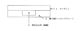
純銅埋め込み型のバッキングプレートの構造を図1に示すが、埋め込み体である純銅は銅−亜鉛合金に抱え込まれる形状を呈している。これは、組立体の一例を示すものである。銅−亜鉛合金に比べ純銅の強度は低いが、このように純銅の周囲を銅−亜鉛合金で包囲する形状は、高温になるバッキングプレートの強度を全体的に維持できる機能を備えているという大きな特徴を有している。
図1に示すような構造のスパッタリングターゲット/銅−亜鉛合金製バッキングプレート組立体では、純銅からなる埋め込み体3の厚さを銅−亜鉛合金製バッキングプレート2の1/4〜2/4とすることが、ターゲット1の除熱効果が大きく、ターゲット/バッキングプレート間の剥離が抑制できるより好ましい構造である。The structure of a pure copper-embedded backing plate is shown in FIG. 1, and the pure copper, which is an embedded body, has a shape held in a copper-zinc alloy. This shows an example of an assembly. The strength of pure copper is lower than that of copper-zinc alloy, but the shape surrounding the pure copper with copper-zinc alloy in this way has the function of maintaining the overall strength of the backing plate that becomes hot. It has characteristics.
In the sputtering target / copper-zinc alloy backing plate assembly having the structure shown in FIG. 1, the thickness of the embedded body 3 made of pure copper is set to 1/4 to 2/4 of the copper-zinc alloy backing plate 2. This is a more preferable structure in which the heat removal effect of the target 1 is large and the separation between the target and the backing plate can be suppressed.
上記抱え込まれる形状のスパッタリングターゲット/バッキングプレート組立体の構造に対して、5)純銅からなる埋め込み体の厚さが銅−亜鉛合金製バッキングプレートの厚さで付き切り(貫通した)構造を持つようにすることもできる。この場合、バッキングプレートの背面からの冷却は、純銅からなる埋め込み体に対しての直接冷却となる。この場合は、冷却媒体と熱伝導に優れた純銅が直接接触するので、ターゲット中心部のより効率的な冷却が可能となる。 In contrast to the structure of the sputtering target / backing plate assembly having the above-described shape, 5) the thickness of the embedded body made of pure copper has the structure of being cut (penetrated) by the thickness of the copper-zinc alloy backing plate. It can also be. In this case, the cooling from the back surface of the backing plate is the direct cooling of the embedded body made of pure copper. In this case, since the pure copper excellent in heat conduction is in direct contact with the cooling medium, more efficient cooling of the center portion of the target is possible.
本発明のスパッタリングターゲット/バッキングプレート組立体は、ターゲット材料の種類を問わず適用できるが、特に高温に加熱される6)ターゲットがタンタルあるいはタンタル基合金ターゲットに有用である。本願発明は、このように高融点金属材料のスパッタリングターゲットに適用できる。
また、本願発明は、7)ターゲットとバッキングプレートが拡散接合された構造を持つスパッタリングターゲット/バッキングプレート組立体に有用である。このような構造は、高融点ターゲットに一般的に必要とされる接合方法であるが、熱影響が極めて大きいことが強固な接合を要求される所以である。そして、本願発明は、それに適応できるスパッタリングターゲット/バッキングプレート組立体を提供できる。The sputtering target / backing plate assembly of the present invention can be applied regardless of the type of target material, but 6) the target heated to a high temperature is particularly useful as a tantalum or tantalum-based alloy target. The present invention can be applied to a sputtering target of a refractory metal material as described above.
The present invention is useful for 7) a sputtering target / backing plate assembly having a structure in which a target and a backing plate are diffusion bonded. Such a structure is a bonding method generally required for a high melting point target, but it is a reason that a strong bonding is required because the heat influence is extremely large. The present invention can provide a sputtering target / backing plate assembly that can be adapted to the above.
本願発明のスパッタリングターゲット/バッキングプレート組立体は、特に渦電流が発生し易い8)マグネトロンスパッタリング装置に、特に有用である。しかし、本願発明のスパッタリングターゲット/バッキングプレート組立体は、このマグネトロンスパッタリング装置に限定される必要はないことを知るべきである。多くの場合、ターゲットの周縁部に比較して中心部はより熱が集中し易いので、ターゲットの均一な冷却を図るためにも、中心部に熱伝導性の高い純銅を使用した本願発明のスパッタリングターゲット/バッキングプレート組立体は有用であるからである。したがって、一般的なスパッタリング装置にも適用できるものである。 The sputtering target / backing plate assembly of the present invention is particularly useful for 8) magnetron sputtering devices that are particularly prone to eddy currents. However, it should be noted that the sputtering target / backing plate assembly of the present invention need not be limited to this magnetron sputtering apparatus. In many cases, heat tends to concentrate more in the center than in the peripheral part of the target. Therefore, in order to achieve uniform cooling of the target, the sputtering of the present invention using pure copper having high thermal conductivity in the center. This is because the target / backing plate assembly is useful. Therefore, it can be applied to a general sputtering apparatus.
本願発明のスパッタリングターゲット/バッキングプレート組立体に使用する埋め込み材料となる純銅としては、9)純銅が無酸素銅を使用することができる。
スパッタリングターゲット/バッキングプレート組立体に使用する10)銅亜鉛合金製バッキングプレートは、5〜40wt%の亜鉛を含有する銅−亜鉛系銅合金を使用することができる。バッキングプレート材として使用する銅−亜鉛合金は、安価であり、強度が高く、熱伝導性に優れ、かつ渦電流の発生を抑制できるからである。As pure copper used as the embedding material used in the sputtering target / backing plate assembly of the present invention, 9) pure copper can use oxygen-free copper.
10) The copper-zinc alloy backing plate used for the sputtering target / backing plate assembly may be a copper-zinc based copper alloy containing 5 to 40 wt% zinc. This is because the copper-zinc alloy used as the backing plate material is inexpensive, has high strength, is excellent in thermal conductivity, and can suppress the generation of eddy currents.
以上によって、本発明は、安価で、強度と耐渦電流特性に優れる銅−亜鉛合金製バッキングプレートを、その特性を低下させること無く、更なるハイパワー化に十分対応できる簡便なスパッタリングターゲット/バッキングプレート構造体を提供することができるという優れた効果を得ることができる。 As described above, the present invention is an inexpensive sputtering target / backing that can sufficiently cope with higher power without lowering the properties of a copper-zinc alloy backing plate that is inexpensive and excellent in strength and eddy current resistance. An excellent effect that a plate structure can be provided can be obtained.
次に、本願発明の具体例を説明する。なお、以下の説明はあくまで一例であり、この例によって本願発明は制限されるものではない。すなわち、本願発明は明細書に記載する全ての記載から把握できる技術思想にのみ制限されるものであり、この例に含まれる以外の種々の変形を包含するものである。 Next, specific examples of the present invention will be described. In addition, the following description is an example to the last and this invention is not restrict | limited by this example. That is, the present invention is limited only to the technical idea that can be grasped from all the descriptions in the specification, and includes various modifications other than those included in this example.
(タンタル/銅−亜鉛合金拡散接合体の熱影響の試験)
タンタル/銅−亜鉛合金拡散接合体バッキングプレートの強度については、これを加熱処理して、亜鉛の蒸発状況を観察することにより確認することができる。ターゲット及びバッキングプレートについては、次の材料を使用した。
ターゲット:タンタル 直径440mm、厚さ4.8mm
銅−亜鉛合金バッキングプレート(合金番号C2600):厚さ17mm
ターゲットと銅−亜鉛合金バッキングプレートの接合:拡散接合(Test of thermal effects of tantalum / copper-zinc alloy diffusion bonded body)
The strength of the tantalum / copper-zinc alloy diffusion bonded backing plate can be confirmed by heat-treating it and observing the state of zinc evaporation. The following materials were used for the target and backing plate.
Target: tantalum diameter 440mm, thickness 4.8mm
Copper-zinc alloy backing plate (Alloy No. C2600): 17mm thickness
Bonding target and copper-zinc alloy backing plate: diffusion bonding
このターゲット/バッキングプレート拡散接合体は、700°Cまでの真空加熱処理では、亜鉛の蒸散は起こらなかった。しかし、900°Cの真空熱処理では、銅−亜鉛合金製バッキングプレート材のタンタル/銅−亜鉛合金の拡散接合部が剥離する現象が生じた。
次に、この結果を数値計算で再現するために、仮想的に最もエロージョンされる中央部の直径50mmの領域に、均一に500W/cm2のパワーを与えた(トータルスパッタパワー10kW:10kWが直径50mmの領域のみに集中的に作用すると仮定した。実際のスパッタリングパワーは40kWであり、これは剥離が発生する場合である。)また、バッキングプレートの背面側(ターゲットの反対側)は水冷した(冷却水の温度は20°Cとした)。In this target / backing plate diffusion bonded body, no transpiration of zinc occurred in the vacuum heat treatment up to 700 ° C. However, in the vacuum heat treatment at 900 ° C., a phenomenon occurred in which the diffusion bonding portion of the tantalum / copper-zinc alloy of the copper-zinc alloy backing plate material was peeled off.
Next, in order to reproduce this result by numerical calculation, a power of 500 W / cm 2 was uniformly applied to a 50 mm diameter region of the central portion that is virtually eroded most (total sputter power of 10 kW: 10 kW is the diameter). (It is assumed that it acts intensively only in the region of 50 mm. Actual sputtering power is 40 kW, which is the case where peeling occurs.) Also, the back side of the backing plate (opposite the target) was water-cooled ( The cooling water temperature was 20 ° C).
数値計算の結果から、タンタルターゲットの表面中央部の最高温度は、1040°Cであった。これは、実際のスパッタリング時のターゲット温度に近いものである。
銅−亜鉛合金製バッキングプレートの中心部、ターゲットとの接合界面の最高温度770°Cとなり、真空熱処理結果の700°Cでは問題が発生しなかったことも考慮にいれると、上記、数値計算条件では、銅亜鉛バッキングプレートがおよそ750°Cを超えると亜鉛の蒸散が起こることから、この態ではターゲット/銅−亜鉛合金製バッキングプレートの剥離が起こることが予想される。From the result of numerical calculation, the maximum temperature at the center of the surface of the tantalum target was 1040 ° C. This is close to the target temperature during actual sputtering.
If the maximum temperature of the bonding interface with the center of the copper-zinc alloy backing plate and the target is 770 ° C, and there is no problem at 700 ° C of the vacuum heat treatment result, the above numerical calculation conditions Then, since the transpiration of zinc occurs when the copper-zinc backing plate exceeds approximately 750 ° C., peeling of the backing plate made of the target / copper-zinc alloy is expected in this state.
以上の実験と数値計算をベースとして、純銅を埋め込んだ各種ターゲット/銅−亜鉛合金製バッキングプレート作製し、銅−亜鉛合金製バッキングプレートの最高温度、スパッタ試験の結果を観察した。数値計算条件は、次の通りである。
ターゲット:タンタル 直径440mm、厚さ4.8mm
銅−亜鉛合金製バッキングプレート(合金番号C2600):厚さ17mm
最もエロージョンされる中央部に、直径50mm、厚さ6mmの埋め込み体を埋設。
最もエロージョンされる中央部の直径50mmの領域に、均一に500W/cm2のパワーを与え、バッキングプレート側は水冷(冷却水の温度は20°Cとした)。
スパッタ条件は、上記形状のターゲット/バッキングプレート組立体をスパッタパワー40kWでスパッタした。Based on the above experiments and numerical calculations, various target / copper-zinc alloy backing plates embedded with pure copper were prepared, and the maximum temperature of the copper-zinc alloy backing plate and the results of the sputtering test were observed. The numerical calculation conditions are as follows.
Target: tantalum diameter 440mm, thickness 4.8mm
Copper-zinc alloy backing plate (Alloy No. C2600): 17mm thickness
An embedded body with a diameter of 50 mm and a thickness of 6 mm is embedded in the most eroded center.
A power of 500 W / cm 2 was uniformly applied to the most eroded region having a diameter of 50 mm, and the backing plate side was water-cooled (cooling water temperature was 20 ° C.).
As the sputtering conditions, the target / backing plate assembly having the above shape was sputtered at a sputtering power of 40 kW.
(実施例1−8及び比較例1−2)
実施例1−7については、表1に示すように純銅埋め込み体の直径を50mmと固定し、厚さを1mm〜15mmまで変化させ、実施例8については銅−亜鉛合金製バッキングプレートを突き切り(貫通させた)構造とした。
また、比較例1については、ターゲットと銅−亜鉛合金製バッキングプレートの間に1mmの純銅インサートを使用し、比較例2については、ターゲットと銅−亜鉛合金製バッキングプレートの間に6mmの純銅インサート材を使用した。(Example 1-8 and Comparative Example 1-2)
For Example 1-7, as shown in Table 1, the diameter of the pure copper embedded body was fixed to 50 mm and the thickness was changed from 1 mm to 15 mm. For Example 8, a copper-zinc alloy backing plate was cut off. A (penetrated) structure was adopted.
For Comparative Example 1, a 1 mm pure copper insert was used between the target and the copper-zinc alloy backing plate. For Comparative Example 2, a 6 mm pure copper insert was used between the target and the copper-zinc alloy backing plate. The material was used.

(スパッタ試験の結果)
数値計算結果から、タンタルターゲットの表面中央部の最高温度1050°Cに達したが、実施例1の厚さ1mmの、純銅製埋め込み体を有する銅−亜鉛合金製バッキングプレートの最高温度は710°Cであり、剥離は起こらず、成膜均一性は可であった。
このように、薄い純銅製埋め込み体を配置しただけでも、銅−亜鉛合金製バッキングプレートの温度低下があり、有効であることが分る。上記の通り、純銅製埋め込み体を使用しない場合、銅−亜鉛合金製バッキングプレートの中心部のターゲットとの接合界面の最高温度770°Cであったが、710°Cと低下し、60°Cの温度低下が可能であった。
表1に示すように、純銅埋込体の厚みが薄いものが、必ずしも成膜均一性が優れているとは言えない。これは、純銅埋込体の厚さが薄いものは、ターゲットの温度分布差が大きいことが原因と考えられる。(Result of sputtering test)
From the numerical calculation results, the maximum temperature at the center of the surface of the tantalum target reached 1050 ° C, but the maximum temperature of the 1 mm thick copper-zinc alloy backing plate of Example 1 having a pure copper embedded body was 710 °. C, peeling did not occur, and film formation uniformity was acceptable.
Thus, it can be seen that even if a thin pure copper embedded body is disposed, the temperature of the copper-zinc alloy backing plate is lowered and effective. As described above, when a pure copper embedded body was not used, the maximum temperature of the bonding interface with the target at the center of the copper-zinc alloy backing plate was 770 ° C, but it decreased to 710 ° C, and 60 ° C The temperature could be lowered.
As shown in Table 1, it can not be said that a thin pure copper embedded body necessarily has excellent film formation uniformity. This is considered to be caused by the fact that the difference in the temperature distribution of the target is large when the pure copper embedded body is thin.
(実施例2−6)
実施例2は、厚さ2mmの、純銅埋め込み体を有する銅−亜鉛合金製バッキングプレートの最高温度は680°Cであり、剥離は起こらず、成膜均一性は可であった。
実施例3は、厚さ3mmの、純銅埋め込み体を有する銅−亜鉛合金製バッキングプレートの最高温度は630°Cであり、剥離は起こらず、成膜均一性は良好であった。
実施例4は、厚さ6mmの、純銅埋め込み体を有する銅−亜鉛合金製バッキングプレートの最高温度は510°Cであり、剥離は起こらず、成膜均一性は優れていた。
実施例5は、厚さ8mmの、純銅埋め込み体を有する銅−亜鉛合金製バッキングプレートの最高温度は470°Cであり、剥離は起こらず、成膜均一性は優れていた。
上記に示すように、純銅埋め込み体の厚さが増加するに従い、成膜均一性は向上し、厚さ6mm、8mmで成膜均一性が最も優れていた。(Example 2-6)
In Example 2, the maximum temperature of a 2 mm thick copper-zinc alloy backing plate having a pure copper embedded body was 680 ° C., peeling did not occur, and film formation uniformity was acceptable.
In Example 3, the maximum temperature of a copper-zinc alloy backing plate having a pure copper embedded body with a thickness of 3 mm was 630 ° C., peeling did not occur, and film formation uniformity was good.
In Example 4, the maximum temperature of a copper-zinc alloy backing plate having a pure copper embedded body with a thickness of 6 mm was 510 ° C., peeling did not occur, and the film formation uniformity was excellent.
In Example 5, the maximum temperature of a copper-zinc alloy backing plate having a thickness of 8 mm and having a pure copper embedded body was 470 ° C., no peeling occurred, and the film formation uniformity was excellent.
As described above, as the thickness of the pure copper embedded body increased, the film formation uniformity improved, and the film formation uniformity was most excellent at thicknesses of 6 mm and 8 mm.
(実施例6−7)
実施例6は、厚さ12mmの、純銅埋め込み体を有する銅−亜鉛合金製バッキングプレートの最高温度は360°Cであり、また、剥離は起こらず、成膜均一性は良好であった。この場合、温度が著しく低下したにもかかわらず、成膜均一性は、純銅埋め込み体の厚さが6mm、8mmの場合よりもやや低下した。これは、厚さの厚い場合は、上述したように渦電流に起因するマグネット回転の変動に起因するものと考えられる。
実施例7は、厚さ15mmの、純銅埋め込み体を有する銅−亜鉛合金製バッキングプレートの最高温度は320°Cであり、また、剥離は起こらず、成膜均一性は可であった。この場合も、温度が著しく低下したにもかかわらず、成膜均一性は、純銅埋め込み体の厚さが6mm、8mmの場合よりも低下した。これは、厚さの厚い場合は、マグネットとの距離が近くなり上述したように渦電流に起因するマグネット回転の変動に起因するものと考えられる。(Example 6-7)
In Example 6, the maximum temperature of a copper-zinc alloy backing plate having a thickness of 12 mm and having a pure copper embedded body was 360 ° C. Further, no peeling occurred and the film formation uniformity was good. In this case, the film formation uniformity was slightly lower than when the thickness of the pure copper embedded body was 6 mm or 8 mm, even though the temperature was remarkably lowered. This is considered to be caused by fluctuations in the rotation of the magnet due to the eddy current as described above when the thickness is large.
In Example 7, the maximum temperature of a copper-zinc alloy backing plate having a pure copper embedded body with a thickness of 15 mm was 320 ° C., peeling did not occur, and film formation uniformity was acceptable. In this case as well, the film formation uniformity was lower than when the thickness of the pure copper embedded body was 6 mm or 8 mm, although the temperature was significantly reduced. This is considered to be caused by fluctuations in the rotation of the magnet due to the eddy current as described above when the thickness is large and the distance from the magnet becomes close.
(実施例8)
実施例8は、厚さ17mmの、純銅埋め込み体を有する銅−亜鉛合金製バッキングプレート、すなわち銅−亜鉛合金製バッキングプレートと同一厚みであり、純銅埋め込み体が貫通した構造のバッキングプレートである。この場合の最高温度は270°Cであり、また、剥離は起こらず、成膜均一性は可であった。この場合、温度が著しく低下し、純銅の冷却効率が良好であることが分る。しかし、成膜均一性は、純銅埋め込み体の厚さが6mm、8mmの場合よりも、低下した。これは、厚さの厚い場合は、マグネットとの距離が近くなり上述したように渦電流に起因するマグネット回転の変動が大きく作用するものと考えられる。(Example 8)
Example 8 is a 17 mm thick copper-zinc alloy backing plate having a pure copper embedded body, that is, a copper-zinc alloy backing plate having the same thickness as the pure copper embedded body. In this case, the maximum temperature was 270 ° C., no peeling occurred, and the film formation was uniform. In this case, it turns out that temperature falls remarkably and the cooling efficiency of pure copper is favorable. However, the film formation uniformity was lower than when the pure copper embedded was 6 mm or 8 mm thick. This is considered that when the thickness is large, the distance from the magnet becomes short, and the fluctuation of the magnet rotation due to the eddy current acts greatly as described above.
(比較例1−2)
上記の通り、比較例1は、ターゲット全面と銅−亜鉛合金製バッキングプレートの間に1mmの純銅インサートを使用し、比較例2については、ターゲット全面と銅−亜鉛合金製バッキングプレートの間に6mmの純銅インサート材を使用した場合である。
比較例1、比較例2は、熱伝導性の高い純銅のインサート効果により、亜鉛合金製バッキングプレートの剥離は起こらなかったが、成膜均一性は不良であった。これは、渦電流に起因するマグネット回転の変動に起因し、純銅のインサートにより、銅−亜鉛合金製バッキングプレートの抑制効果が減殺されたものと考えられる。(Comparative Example 1-2)
As described above, Comparative Example 1 uses a 1 mm pure copper insert between the entire surface of the target and the copper-zinc alloy backing plate. In Comparative Example 2, 6 mm between the entire surface of the target and the copper-zinc alloy backing plate. This is a case where a pure copper insert material is used.
In Comparative Examples 1 and 2, peeling of the zinc alloy backing plate did not occur due to the insert effect of pure copper having high thermal conductivity, but the film formation uniformity was poor. This is attributed to fluctuations in the rotation of the magnet due to eddy current, and it is considered that the suppression effect of the copper-zinc alloy backing plate was reduced by the pure copper insert.
(実施例9−10)
次に、上記スパッタ試験結果が優れていた純銅埋め込み体の厚さを6mmに固定し、純銅埋め込み体の直径を変化させた場合の、試験結果を表2に示す。
ターゲット及びバッキングプレートの条件は、上記と同様である(再掲)。ターゲットの直径に対する純銅埋め込み体の直径の比で示した。
ターゲット:タンタル 直径440mm、厚さ4.8mm
銅−亜鉛合金製バッキングプレート(合金番号C2600):厚さ17mm
実施例9は、純銅埋め込み体の直径:ターゲットの直径=1:2の場合であるが、銅−亜鉛合金製バッキングプレートの最高温度は420°Cであり、剥離は起こらず、成膜均一性は良好であった。
実施例10は、純銅埋め込み体の直径:ターゲットの直径=1:5の場合であるが、銅−亜鉛合金製バッキングプレートの最高温度は470°Cであり、剥離は起こらず、成膜均一性は優れていた。この結果を表2に示す。(Example 9-10)
Next, Table 2 shows test results when the thickness of the pure copper embedded body in which the sputter test result was excellent was fixed to 6 mm and the diameter of the pure copper embedded body was changed.
The conditions of the target and the backing plate are the same as above (reprinted). The ratio of the diameter of the pure copper embedded body to the target diameter is shown.
Target: tantalum diameter 440mm, thickness 4.8mm
Copper-zinc alloy backing plate (Alloy No. C2600): 17mm thickness
Example 9 is the case of pure copper embedded body diameter: target diameter = 1: 2, but the maximum temperature of the copper-zinc alloy backing plate is 420 ° C., peeling does not occur, and film formation uniformity Was good.
Example 10 is a case where the diameter of the pure copper embedded body: the target diameter = 1: 5, but the maximum temperature of the copper-zinc alloy backing plate is 470 ° C., peeling does not occur, and film formation uniformity Was excellent. The results are shown in Table 2.
(実施例11−13)
実施例11は、純銅埋め込み体の直径:ターゲットの直径=1:7.5の場合であるが、銅−亜鉛合金製バッキングプレートの最高温度は500°Cであり、剥離は起こらず、成膜均一性は優れていた。
実施例12は、純銅埋め込み体の直径:ターゲットの直径=1:10の場合であるが、銅−亜鉛合金製バッキングプレートの最高温度は530°Cであり、剥離は起こらず、成膜均一性は良好であった。
実施例13は、純銅埋め込み体の直径:ターゲットの直径=1:20の場合であるが、銅−亜鉛合金製バッキングプレートの最高温度は690°Cであり、剥離は起こらず、成膜均一性は可であった。(Examples 11-13)
In Example 11, the diameter of the pure copper embedded body: the target diameter = 1: 7.5, but the maximum temperature of the copper-zinc alloy backing plate was 500 ° C., and no peeling occurred, and the film was formed. The uniformity was excellent.
Example 12 is the case of pure copper embedded body diameter: target diameter = 1: 10, but the maximum temperature of the copper-zinc alloy backing plate is 530 ° C., no peeling occurs, and film formation uniformity Was good.
Example 13 is a case of pure copper embedded body diameter: target diameter = 1: 20, but the maximum temperature of the copper-zinc alloy backing plate is 690 ° C., and no peeling occurs, and the film formation uniformity Was possible.
(比較例3)
比較例3は、純銅埋め込み体の直径:ターゲットの直径=1:1.5の場合であるが、銅−亜鉛合金製バッキングプレートの最高温度は400°Cであり、剥離は起こらなかったが、成膜均一性は不良であった。これは純銅埋め込み体の直径が大き過ぎ、渦電流に起因するマグネット回転の変動に起因して成膜均一性が悪くなったもの、すなわち、純銅のインサートにより、銅−亜鉛合金製バッキングプレートの抑制効果が減殺されたものと考えられる。(Comparative Example 3)
Comparative Example 3 is a case of pure copper embedded body diameter: target diameter = 1: 1.5, but the maximum temperature of the copper-zinc alloy backing plate was 400 ° C., and peeling did not occur. The film formation uniformity was poor. This is because the pure copper embedded body is too large in diameter, and the film deposition uniformity has deteriorated due to fluctuations in magnet rotation caused by eddy currents, that is, the copper-zinc alloy backing plate is suppressed by the pure copper insert. It is thought that the effect was reduced.
(比較例4−5)
比較例4は、純銅埋め込み体の直径:ターゲットの直径=1:30の場合であるが、銅−亜鉛合金製バッキングプレートの最高温度は750°Cを超え、剥離が発生した。
これは純銅埋め込み体の直径が小さすぎ、熱拡散の効果が十分でなく、銅−亜鉛合金製バッキングプレートに一部溶融が生じたものである。
比較例5は、純銅埋め込み体の直径:ターゲットの直径=1:40の場合であるが、銅−亜鉛合金製バッキングプレートの最高温度は750°Cを超え、剥離が発生した。上記比較例4よりも、その状態は悪化した。
これは純銅埋め込み体の直径が小さすぎ、熱拡散の効果が十分でなく、銅−亜鉛合金製バッキングプレートに一部溶融が生じたものである。(Comparative Example 4-5)
In Comparative Example 4, the diameter of the pure copper embedded body: the target diameter = 1: 30, but the maximum temperature of the copper-zinc alloy backing plate exceeded 750 ° C., and peeling occurred.
This is because the diameter of the pure copper embedded body is too small and the effect of thermal diffusion is not sufficient, and the copper-zinc alloy backing plate is partially melted.
In Comparative Example 5, the diameter of the pure copper embedded body: the target diameter = 1: 40, but the maximum temperature of the copper-zinc alloy backing plate exceeded 750 ° C., and peeling occurred. The state was worse than that of Comparative Example 4 above.
This is because the diameter of the pure copper embedded body is too small and the effect of thermal diffusion is not sufficient, and the copper-zinc alloy backing plate is partially melted.
以上の例から明らかなように、純銅埋め込み体の直径の比率が増加すると、銅−亜鉛合金製バッキングプレートの温度は低下するが、成膜均一性はそれほど向上しない。
一方、純銅埋め込み体の直径に比率が減少すると、銅−亜鉛合金製バッキングプレートの温度は上昇するが、成膜均一性が優れたものとなる。
しかし、その比率が極端に少なくなると、純銅埋め込み体の効果が減少し、成膜の均一性も低下してくる。以上から、いずれの場合も、最適条件が存在することが分る。
すなわち、純銅からなる埋め込み体の直径がターゲット直径の1/20〜1/2であること、さらには、純銅からなる埋め込み体の厚さがバッキングプレートの1/5〜4/5であることが、より望ましいことが分る。As is clear from the above examples, when the diameter ratio of the pure copper embedded body increases, the temperature of the copper-zinc alloy backing plate decreases, but the film formation uniformity does not improve so much.
On the other hand, when the ratio decreases to the diameter of the pure copper embedded body, the temperature of the copper-zinc alloy backing plate rises, but the film formation uniformity is excellent.
However, when the ratio is extremely reduced, the effect of the pure copper embedded body is reduced and the uniformity of film formation is also lowered. From the above, it can be seen that an optimum condition exists in any case.
That is, the diameter of the embedded body made of pure copper is 1/20 to 1/2 of the target diameter, and the thickness of the embedded body made of pure copper is 1/5 to 4/5 of the backing plate. Find out more desirable.
本発明は、安価で、強度と耐渦電流特性に優れる銅−亜鉛合金製バッキングプレートを、その特性を低下させること無く、更なるハイパワー化に十分対応できる簡便なスパッタリングターゲット/バッキングプレート構造体を提供することができるという優れた効果を有し、特にターゲットがタンタルあるいはタンタル基合金等の高融点ターゲット材をスパッタする場合に有用である。 The present invention provides a simple sputtering target / backing plate structure that is inexpensive and can sufficiently cope with higher power without lowering the properties of a copper-zinc alloy backing plate having excellent strength and eddy current resistance. This is particularly useful when the target is sputtered with a high melting point target material such as tantalum or a tantalum-based alloy.
Claims (10)
Priority Applications (1)
| Application Number | Priority Date | Filing Date | Title |
|---|---|---|---|
| JP2008522336A JP4879986B2 (en) | 2006-06-29 | 2007-05-02 | Sputtering target / backing plate assembly |
Applications Claiming Priority (4)
| Application Number | Priority Date | Filing Date | Title |
|---|---|---|---|
| JP2006179930 | 2006-06-29 | ||
| JP2006179930 | 2006-06-29 | ||
| JP2008522336A JP4879986B2 (en) | 2006-06-29 | 2007-05-02 | Sputtering target / backing plate assembly |
| PCT/JP2007/059359 WO2008001547A1 (en) | 2006-06-29 | 2007-05-02 | Sputtering target/backing plate conjunction element |
Publications (2)
| Publication Number | Publication Date |
|---|---|
| JPWO2008001547A1 JPWO2008001547A1 (en) | 2009-11-26 |
| JP4879986B2 true JP4879986B2 (en) | 2012-02-22 |
Family
ID=38845319
Family Applications (1)
| Application Number | Title | Priority Date | Filing Date |
|---|---|---|---|
| JP2008522336A Active JP4879986B2 (en) | 2006-06-29 | 2007-05-02 | Sputtering target / backing plate assembly |
Country Status (7)
| Country | Link |
|---|---|
| US (1) | US8157973B2 (en) |
| EP (1) | EP2039797B1 (en) |
| JP (1) | JP4879986B2 (en) |
| KR (1) | KR101040076B1 (en) |
| CN (1) | CN101479400B (en) |
| TW (1) | TW200801216A (en) |
| WO (1) | WO2008001547A1 (en) |
Families Citing this family (16)
| Publication number | Priority date | Publication date | Assignee | Title |
|---|---|---|---|---|
| CN102230158B (en) * | 2004-11-17 | 2014-04-30 | Jx日矿日石金属株式会社 | Sputtering target, sputtering target backing plate assembly and film deposition system |
| JP5676429B2 (en) * | 2008-04-21 | 2015-02-25 | ハネウェル・インターナショナル・インコーポレーテッド | Design and use of DC magnetron sputtering system |
| WO2011062002A1 (en) | 2009-11-20 | 2011-05-26 | Jx日鉱日石金属株式会社 | (sputtering target)-(bucking plate) joint body, and process for production thereof |
| KR101445945B1 (en) | 2009-12-24 | 2014-09-29 | 제이엑스 닛코 닛세키 킨조쿠 가부시키가이샤 | Gadolinium sputtering target and method for manufacturing the target |
| JP5694360B2 (en) | 2010-10-27 | 2015-04-01 | Jx日鉱日石金属株式会社 | Sputtering target-backing plate assembly and manufacturing method thereof |
| US8968537B2 (en) * | 2011-02-09 | 2015-03-03 | Applied Materials, Inc. | PVD sputtering target with a protected backing plate |
| JP2014523969A (en) | 2011-06-27 | 2014-09-18 | ソレラス・リミテッド | Sputtering target |
| WO2015068625A1 (en) * | 2013-11-06 | 2015-05-14 | Jx日鉱日石金属株式会社 | Sputtering target/backing plate assembly |
| JP6130075B2 (en) | 2014-07-31 | 2017-05-17 | Jx金属株式会社 | Backing plate in which corrosion-resistant metal and Mo or Mo alloy are diffusion-bonded, and sputtering target-backing plate assembly including the backing plate |
| JP6021861B2 (en) * | 2014-08-06 | 2016-11-09 | Jx金属株式会社 | Sputtering target-backing plate assembly |
| KR101649794B1 (en) | 2014-08-20 | 2016-08-19 | 김정욱 | Tower lamp information managing system for monitoring tower lamp state |
| JP6546953B2 (en) | 2017-03-31 | 2019-07-17 | Jx金属株式会社 | Sputtering target-backing plate assembly and method for manufacturing the same |
| US11244815B2 (en) | 2017-04-20 | 2022-02-08 | Honeywell International Inc. | Profiled sputtering target and method of making the same |
| KR102263414B1 (en) | 2020-02-19 | 2021-06-10 | 주식회사 엘에이티 | Sputter electrode body |
| CN113173284B (en) * | 2021-04-26 | 2022-07-15 | 宁波江丰电子材料股份有限公司 | Management method of semi-finished target backboard |
| KR20230072292A (en) | 2021-11-17 | 2023-05-24 | 바짐테크놀로지 주식회사 | Sputtering target assembly |
Citations (6)
| Publication number | Priority date | Publication date | Assignee | Title |
|---|---|---|---|---|
| JPS6345368A (en) * | 1986-08-13 | 1988-02-26 | Toshiba Corp | Sputtering device |
| JPH11189870A (en) * | 1997-12-25 | 1999-07-13 | Nisshin Steel Co Ltd | Target for sputtering and cooling method therefor |
| JP2002129316A (en) * | 2000-10-31 | 2002-05-09 | Nikko Materials Co Ltd | Assembly composed of tantalum or tungsten target and packing plate made from copper alloy, and manufacturing method therefor |
| WO2005007920A2 (en) * | 2003-07-14 | 2005-01-27 | Tosoh Smd, Inc. | Sputtering target assembly having low conductivity backing plate and method of making same |
| WO2005064036A1 (en) * | 2003-12-25 | 2005-07-14 | Nikko Materials Co., Ltd. | Copper or copper alloy target/copper alloy backing plate assembly |
| WO2006054409A1 (en) * | 2004-11-17 | 2006-05-26 | Nippon Mining & Metals Co., Ltd. | Sputtering target, sputtering target backing plate assembly and film deposition system |
Family Cites Families (17)
| Publication number | Priority date | Publication date | Assignee | Title |
|---|---|---|---|---|
| JPH01222047A (en) | 1988-03-01 | 1989-09-05 | Nippon Mining Co Ltd | Backing plate made of copper or copper alloy |
| JPH0774436B2 (en) * | 1990-09-20 | 1995-08-09 | 富士通株式会社 | Thin film formation method |
| US5693203A (en) * | 1992-09-29 | 1997-12-02 | Japan Energy Corporation | Sputtering target assembly having solid-phase bonded interface |
| JP3660014B2 (en) | 1995-03-31 | 2005-06-15 | 株式会社テクノファイン | Sputtering target |
| JP2001329362A (en) | 2000-05-17 | 2001-11-27 | Nikko Materials Co Ltd | Backing plate and sputtering target-backing plate assembled body |
| JP3791829B2 (en) * | 2000-08-25 | 2006-06-28 | 株式会社日鉱マテリアルズ | Sputtering target with less generation of particles |
| JP3905295B2 (en) * | 2000-10-02 | 2007-04-18 | 日鉱金属株式会社 | Diffusion bonding target assembly of high purity cobalt target and copper alloy backing plate and method for manufacturing the same |
| EP1312695B1 (en) * | 2000-11-17 | 2009-07-29 | Nippon Mining & Metals Co., Ltd. | Sputtering target producing few particles, backing plate provided with the target, and a method of producing the target |
| US7115193B2 (en) * | 2001-03-14 | 2006-10-03 | Nippon Mining & Metals Co., Ltd. | Sputtering target producing very few particles, backing plate or apparatus within sputtering device and roughening method by electric discharge machining |
| WO2003052161A1 (en) * | 2001-12-19 | 2003-06-26 | Nikko Materials Company, Limited | Method for connecting magnetic substance target to backing plate, and magnetic substance target |
| US6709557B1 (en) * | 2002-02-28 | 2004-03-23 | Novellus Systems, Inc. | Sputter apparatus for producing multi-component metal alloy films and method for making the same |
| TWI269815B (en) * | 2002-05-20 | 2007-01-01 | Tosoh Smd Inc | Replaceable target sidewall insert with texturing |
| US20040016635A1 (en) * | 2002-07-19 | 2004-01-29 | Ford Robert B. | Monolithic sputtering target assembly |
| US8177947B2 (en) * | 2005-04-28 | 2012-05-15 | Jx Nippon Mining & Metals Corporation | Sputtering target |
| EP1942204B1 (en) * | 2005-10-04 | 2012-04-25 | JX Nippon Mining & Metals Corporation | Sputtering target |
| US20070125646A1 (en) * | 2005-11-25 | 2007-06-07 | Applied Materials, Inc. | Sputtering target for titanium sputtering chamber |
| US20080236738A1 (en) * | 2007-03-30 | 2008-10-02 | Chi-Fung Lo | Bonded sputtering target and methods of manufacture |
-
2007
- 2007-05-02 CN CN2007800243834A patent/CN101479400B/en active Active
- 2007-05-02 US US12/306,734 patent/US8157973B2/en active Active
- 2007-05-02 JP JP2008522336A patent/JP4879986B2/en active Active
- 2007-05-02 WO PCT/JP2007/059359 patent/WO2008001547A1/en active Application Filing
- 2007-05-02 KR KR1020087031070A patent/KR101040076B1/en active IP Right Grant
- 2007-05-02 EP EP07742794A patent/EP2039797B1/en active Active
- 2007-05-11 TW TW096116790A patent/TW200801216A/en unknown
Patent Citations (6)
| Publication number | Priority date | Publication date | Assignee | Title |
|---|---|---|---|---|
| JPS6345368A (en) * | 1986-08-13 | 1988-02-26 | Toshiba Corp | Sputtering device |
| JPH11189870A (en) * | 1997-12-25 | 1999-07-13 | Nisshin Steel Co Ltd | Target for sputtering and cooling method therefor |
| JP2002129316A (en) * | 2000-10-31 | 2002-05-09 | Nikko Materials Co Ltd | Assembly composed of tantalum or tungsten target and packing plate made from copper alloy, and manufacturing method therefor |
| WO2005007920A2 (en) * | 2003-07-14 | 2005-01-27 | Tosoh Smd, Inc. | Sputtering target assembly having low conductivity backing plate and method of making same |
| WO2005064036A1 (en) * | 2003-12-25 | 2005-07-14 | Nikko Materials Co., Ltd. | Copper or copper alloy target/copper alloy backing plate assembly |
| WO2006054409A1 (en) * | 2004-11-17 | 2006-05-26 | Nippon Mining & Metals Co., Ltd. | Sputtering target, sputtering target backing plate assembly and film deposition system |
Also Published As
| Publication number | Publication date |
|---|---|
| CN101479400B (en) | 2011-06-22 |
| US20090277788A1 (en) | 2009-11-12 |
| WO2008001547A1 (en) | 2008-01-03 |
| TWI353390B (en) | 2011-12-01 |
| KR20090016599A (en) | 2009-02-16 |
| JPWO2008001547A1 (en) | 2009-11-26 |
| CN101479400A (en) | 2009-07-08 |
| TW200801216A (en) | 2008-01-01 |
| US8157973B2 (en) | 2012-04-17 |
| EP2039797A1 (en) | 2009-03-25 |
| KR101040076B1 (en) | 2011-06-09 |
| EP2039797A4 (en) | 2010-04-28 |
| EP2039797B1 (en) | 2012-08-29 |
Similar Documents
| Publication | Publication Date | Title |
|---|---|---|
| JP4879986B2 (en) | Sputtering target / backing plate assembly | |
| CN108914073B (en) | Sputtering target with back cooling groove | |
| JP4331727B2 (en) | Joining method and apparatus | |
| JP5420685B2 (en) | Cu-Mn alloy sputtering target and semiconductor wiring | |
| JP2006073863A (en) | Copper alloy wiring for semiconductor, sputtering target and forming method of copper alloy wiring for semiconductor | |
| TWI488985B (en) | And a method for manufacturing the target | |
| JPS6378740A (en) | Layer composite material with diffusion preventive layer particularly for sliding bearing and manufacture thereof | |
| CN105369204B (en) | Sputtering target backing plate conjugant | |
| JP2007534834A (en) | Sputtering target assembly having low conductivity support plate and manufacturing method thereof | |
| TWI681867B (en) | Corrosion-resistant metal and Mo or Mo alloy diffusion bonded back plate, and sputtering target-back plate assembly with the back plate | |
| JP2012156545A (en) | Copper alloy wire for semiconductor and sputtering target, and method for forming copper alloy wire for semiconductor | |
| JP2004193546A (en) | Copper alloy sputtering target for forming semiconductor device interconnect line seed layer | |
| JP2007242951A (en) | Barrier film for semiconductor wiring, copper wiring for semiconductor, manufacturing method of this wiring, and sputtering target for forming semiconductor barrier film | |
| JP5694503B2 (en) | SEED LAYER WITH SELF-DIFFUSION SUPPRESSING FUNCTION AND METHOD FOR FORMING SEED LAYER HAVING SELF-DIFFUSION SUPPRESSING FUNCTION | |
| JP2004193551A (en) | Copper alloy sputtering target for forming semiconductor device interconnect line seed layer, and semiconductor device interconnect line seed layer |
Legal Events
| Date | Code | Title | Description |
|---|---|---|---|
| A711 | Notification of change in applicant |
Free format text: JAPANESE INTERMEDIATE CODE: A712 Effective date: 20100820 |
|
| TRDD | Decision of grant or rejection written | ||
| A01 | Written decision to grant a patent or to grant a registration (utility model) |
Free format text: JAPANESE INTERMEDIATE CODE: A01 Effective date: 20111129 |
|
| A01 | Written decision to grant a patent or to grant a registration (utility model) |
Free format text: JAPANESE INTERMEDIATE CODE: A01 |
|
| A61 | First payment of annual fees (during grant procedure) |
Free format text: JAPANESE INTERMEDIATE CODE: A61 Effective date: 20111130 |
|
| R150 | Certificate of patent or registration of utility model |
Ref document number: 4879986 Country of ref document: JP Free format text: JAPANESE INTERMEDIATE CODE: R150 Free format text: JAPANESE INTERMEDIATE CODE: R150 |
|
| FPAY | Renewal fee payment (event date is renewal date of database) |
Free format text: PAYMENT UNTIL: 20141209 Year of fee payment: 3 |
|
| S531 | Written request for registration of change of domicile |
Free format text: JAPANESE INTERMEDIATE CODE: R313531 |
|
| S533 | Written request for registration of change of name |
Free format text: JAPANESE INTERMEDIATE CODE: R313533 |
|
| R350 | Written notification of registration of transfer |
Free format text: JAPANESE INTERMEDIATE CODE: R350 |
|
| R250 | Receipt of annual fees |
Free format text: JAPANESE INTERMEDIATE CODE: R250 |
|
| R250 | Receipt of annual fees |
Free format text: JAPANESE INTERMEDIATE CODE: R250 |
|
| R250 | Receipt of annual fees |
Free format text: JAPANESE INTERMEDIATE CODE: R250 |
|
| R250 | Receipt of annual fees |
Free format text: JAPANESE INTERMEDIATE CODE: R250 |
|
| S531 | Written request for registration of change of domicile |
Free format text: JAPANESE INTERMEDIATE CODE: R313531 |
|
| R350 | Written notification of registration of transfer |
Free format text: JAPANESE INTERMEDIATE CODE: R350 |
|
| R250 | Receipt of annual fees |
Free format text: JAPANESE INTERMEDIATE CODE: R250 |
|
| R250 | Receipt of annual fees |
Free format text: JAPANESE INTERMEDIATE CODE: R250 |