JP4879042B2 - Hydraulic control device for work vehicle - Google Patents
Hydraulic control device for work vehicle Download PDFInfo
- Publication number
- JP4879042B2 JP4879042B2 JP2007040557A JP2007040557A JP4879042B2 JP 4879042 B2 JP4879042 B2 JP 4879042B2 JP 2007040557 A JP2007040557 A JP 2007040557A JP 2007040557 A JP2007040557 A JP 2007040557A JP 4879042 B2 JP4879042 B2 JP 4879042B2
- Authority
- JP
- Japan
- Prior art keywords
- passage
- port
- neutral
- valve
- switching
- Prior art date
- Legal status (The legal status is an assumption and is not a legal conclusion. Google has not performed a legal analysis and makes no representation as to the accuracy of the status listed.)
- Expired - Fee Related
Links
Images

Description
この発明は、クローラで走行する作業車両およびホイールで走行する作業車両のいずれにも用いることができる油圧制御装置に関する。 The present invention relates to a hydraulic control device that can be used for both a work vehicle that runs on a crawler and a work vehicle that runs on a wheel.
例えば、パワーショベルのような作業車両には、走行系のアクチュエータと作業機系のアクチュエータとが備えられている。こうした作業車両には、走行中に作業機系のアクチュエータを作動することができるものと、走行中には作業機系のアクチュエータを作動する必要がないものとがある。
具体的には、クローラ仕様のパワーショベルにおいては、走行系のアクチュエータと作業機系のアクチュエータとに同時に圧油を供給するようにしており、走行しながら作業機系のアクチュエータを作動することができる。一方、ホイール仕様のパワーショベルにおいては、路面走行を前提としているため、走行中に作業機系のアクチュエータを作動する必要性がない。そのため、走行系のアクチュエータに圧油を供給する場合に、作業機系のアクチュエータへの圧油供給を停止しても構わない。
For example, a work vehicle such as a power shovel includes a travel system actuator and a work machine system actuator. Such work vehicles include those that can operate a work machine system actuator while traveling and those that do not require a work machine system actuator to operate during travel.
Specifically, in a crawler-type power shovel, pressure oil is supplied simultaneously to the traveling system actuator and the work machine system actuator so that the work machine system actuator can be operated while traveling. . On the other hand, since a wheel-type power shovel is premised on road running, there is no need to operate an actuator of a work implement system during running. Therefore, when supplying pressure oil to the traveling system actuator, the supply of pressure oil to the work machine system actuator may be stopped.
上記のような作業車両における油圧制御装置として、特許文献1に示す発明が従来知られている。この油圧制御装置は、走行系および作業機系のアクチュエータを制御する一対の回路系統をバルブボディに設けるとともに、これら両回路系統のそれぞれにポンプを接続している。そして、バルブボディに設けた両回路系統には、各アクチュエータを制御する複数の切換弁を設けるとともに、これら各切換弁をポンプに対してタンデムに接続している。また、各切換弁のうち最上流に位置する切換弁は、走行系のアクチュエータを制御するようにしている。
このように、走行系のアクチュエータを制御する切換弁を最上流に位置させるとともに、走行用の切換弁を切り換えたときに、その下流側に位置する作業用の切換弁をポンプから遮断すれば、走行系のアクチュエータを優先的に作動することができる。
As a hydraulic control device for a work vehicle as described above, the invention disclosed in
In this way, when the switching valve for controlling the actuator of the traveling system is positioned at the most upstream, and when the switching valve for traveling is switched, the working switching valve located downstream thereof is shut off from the pump, The travel system actuator can be operated with priority.
なお、特許文献1に示す油圧制御装置は、クローラ仕様を前提とするものであり、ホイール仕様の場合には、走行系の回路構成が異なる。
ただし、作業機系の構成、すなわち両回路系統において、最上流に位置する切換弁よりも下流側の構成は、クローラ仕様とホイール仕様とで異にしなければならない部分は特にない。
However, the configuration of the work implement system, that is, the configuration on the downstream side of the switching valve located in the uppermost stream in both circuit systems, is not particularly required to be different between the crawler specification and the wheel specification.
上記作業車両用の油圧制御装置においては、クローラ仕様の場合とホイール仕様の場合とで走行系の回路構成が異なる。そのため、作業機系の回路構成が全く同じであるにも関わらず、クローラ仕様の場合とホイール仕様の場合とで油圧制御装置を共有することができない。
つまり、製造現場においては、注文に応じるために、ホイール仕様の作業車両に搭載する油圧制御装置と、クローラ仕様の作業車両に搭載する油圧制御装置とを、別々にストックしておかなければならず、在庫管理が煩雑になるという問題があった。
In the hydraulic control apparatus for work vehicles described above, the circuit configuration of the traveling system differs between the crawler specification and the wheel specification. Therefore, the hydraulic control device cannot be shared between the crawler specification and the wheel specification even though the circuit configuration of the work machine system is exactly the same.
In other words, at the manufacturing site, the hydraulic control device mounted on the wheel specification work vehicle and the hydraulic control device mounted on the crawler specification work vehicle must be stocked separately in order to fulfill orders. There is a problem that inventory management becomes complicated.
この発明の目的は、走行系の回路構成が異なっても、作業機系の回路構成が同じ作業車両に共通して用いることができる油圧制御装置を提供することである。 An object of the present invention is to provide a hydraulic control device that can be used in common for work vehicles having the same work machine system circuit configuration even when the travel system circuit configuration is different.
この発明は、バルブボディには、第1ポンプ通路を介して第1ポンプに接続した第1回路系統と、第2ポンプ通路を介して第2ポンプに接続した第2回路系統とを設け、上記第1回路系統には、中立時に中立流路を開状態に保ち、中立位置以外の切換位置でこの中立流路を絞り状態もしくは閉状態に保ち、かつ、その切換位置で供給ポート、タンクポート、アクチュエータポートを開閉する複数の切換弁と、上記各中立流路をタンデムに接続する第1センターバイパス通路と、最上流に位置する切換弁よりも下流側における上記第1センターバイパス通路を、上記最上流の切換弁よりも下流側に位置する全部またはいずれかの切換弁の供給ポートに接続する第1パラレル通路とを備え、上記最上流の切換弁は、その中立流路および供給ポートのそれぞれを上記第1ポンプ通路に接続してなる一方、第2回路系統には、中立時に中立流路を開状態に保ち、中立位置以外の切換位置でこの中立流路を絞り状態もしくは閉状態に保ち、かつ、その切換位置で供給ポート、タンクポート、アクチュエータポートを開閉する複数の切換弁と、これら中立流路をタンデムに接続する第2センターバイパス通路と、各切換弁の供給ポートに接続されるとともに、上記第2ポンプ通路を介して第2ポンプに接続した第2パラレル通路とを備えてなる作業車両用の油圧制御装置を前提とする。 In this invention, the valve body is provided with a first circuit system connected to the first pump via the first pump passage and a second circuit system connected to the second pump via the second pump passage, In the first circuit system, the neutral flow path is kept open at the neutral position, the neutral flow path is kept in the throttled state or the closed state at the switching position other than the neutral position, and the supply port, tank port, A plurality of switching valves that open and close the actuator port, a first center bypass passage that connects each of the neutral flow paths in tandem, and the first center bypass passage that is located downstream of the switching valve that is positioned on the most upstream side, A first parallel passage connected to the supply port of all or any of the switching valves located downstream of the upstream switching valve, the uppermost switching valve having its neutral flow path and supply port While each is connected to the first pump passage, in the second circuit system, the neutral flow path is kept open when neutral, and the neutral flow path is set to a throttled state or closed state at a switching position other than the neutral position. A plurality of switching valves that open and close the supply port, tank port, and actuator port at the switching position, a second center bypass passage that connects these neutral flow paths in tandem, and a supply port of each switching valve. And a hydraulic control device for a work vehicle comprising a second parallel passage connected to the second pump via the second pump passage.
上記の構成を前提として、第1の発明は、他のバルブセクションであるサブボディを連接するための上記バルブボディの連接面には、上記第1ポンプ通路に連通する分岐通路を開口してなる第1通路口と、上記第1パラレル通路に連通する分岐通路を開口してなる第2通路口と、上記第2ポンプ通路に連通する分岐通路を開口してなる第3通路口と、第2回路系統の最上流の切換弁における中立流路および供給ポートに連通する分岐通路を開口してなる第4通路口とを形成した点に特徴を有する。 On the premise of the above configuration, the first aspect of the present invention is that a connecting passage of the valve body for connecting a sub-body which is another valve section is provided with a branch passage communicating with the first pump passage. A first passage port, a second passage port that opens a branch passage that communicates with the first parallel passage, a third passage port that opens a branch passage that communicates with the second pump passage, and a second circuit It is characterized in that a neutral flow path in the most upstream switching valve of the system and a fourth passage opening formed by opening a branch passage communicating with the supply port are formed.
第2の発明は、上記バルブボディの連接面には他のバルブセクションであるクローラ用のサブボディを固定してなり、このサブボディには、上記第1通路口と第2通路口とを接続する第1連通通路と、上記第3通路口と第4通路口とを接続する第2連通通路とを設けるとともに、これら両連通通路にはセレクタバルブを接続してなり、このセレクタバルブは、所定の切り換え位置で第1連通通路および第2連通通路を連通状態に維持する一方、上記所定の切り換え位置から切り換わったとき、上記第1通路口を第4通路口に連通させるとともに、上記第3通路口を第2通路口に連通させる構成にした点に特徴を有する。 According to a second aspect of the present invention, a crawler sub-body which is another valve section is fixed to the connecting surface of the valve body, and the first passage port and the second passage port are connected to the sub-body. A communication passage and a second communication passage connecting the third passage port and the fourth passage port are provided, and a selector valve is connected to both the communication passages. The first communication passage and the second communication passage are maintained in communication with each other at the position, and when switched from the predetermined switching position, the first passage port is communicated with the fourth passage port, and the third passage port Is characterized in that it is configured to communicate with the second passage port.
第3の発明は、上記バルブボディの連接面には他のバルブセクションであるホイール用のサブボディを固定してなり、このサブボディには、中立時に中立流路を開状態に保ち、中立位置以外の切換位置でこの中立流路を絞り状態もしくは閉状態に保ち、かつ、その切換位置で供給ポート、タンクポート、アクチュエータポートを開閉する走行用切換弁と、この走行用切換弁の供給ポートと上記第1通路口を連通する第1接続通路と、走行用切換弁の中立時に中立流路を介して上記第3通路口と第4通路口とを連通する第2接続通路と、上記第2通路口を遮断する遮断部とを備えた点に特徴を有する。 According to a third aspect of the present invention, a wheel sub-body, which is another valve section, is fixed to the connecting surface of the valve body. The sub-body maintains a neutral flow path open when neutral, and other than the neutral position. A traveling switching valve that keeps the neutral flow path in a throttled or closed state at the switching position and opens and closes the supply port, the tank port, and the actuator port at the switching position, the supply port of the traveling switching valve, A first connection passage that communicates with one passage port; a second connection passage that communicates the third passage port with the fourth passage port via a neutral flow channel when the travel switching valve is neutral; and the second passage port It has a feature in that it includes a blocking portion that blocks the.
第1〜3の発明によれば、クローラ仕様とホイール仕様とで共通に用いることができる回路構成をバルブボディに備えるとともに、両仕様において異なる回路構成部分に連通する所定の通路を、他のバルブセクションであるサブボディを連接するための連接面に開口させた。つまり、クローラ仕様とホイール仕様とで共通して用いることができる部分のみをバルブボディに形成したので、両仕様の作業車両にバルブボディを共通して用いることが可能となり、作業現場におけるストックを減らして、在庫管理を容易にすることができる。
また、両仕様において異なる回路構成部分に連通する所定の通路を、バルブボディの連接面に開口させたので、仕様に応じて異なる回路を構成したサブボディを当該面に固定するだけで、容易に油圧制御装置としての機能を発揮させることができる。
According to the first to third aspects of the invention, the valve body is provided with a circuit configuration that can be used in common between the crawler specification and the wheel specification, and a predetermined passage that communicates with different circuit components in both specifications is provided to other valves. The sub-body, which is a section, was opened on the connecting surface for connecting. In other words, because only the part that can be used in common between the crawler specification and the wheel specification is formed in the valve body, it is possible to use the valve body in common on both specification work vehicles, reducing stock on the work site. Inventory management can be facilitated.
In addition, since a predetermined passage communicating with different circuit components in both specifications is opened in the connecting surface of the valve body, it is easy to hydraulically simply fix the sub-body that configures different circuits according to the specifications to the surface. The function as a control device can be exhibited.
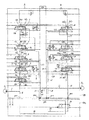
図1,2を用いて、この発明の実施形態について説明する。なお、図1は、バルブボディVBとサブボディSB1とによって、クローラ仕様の油圧回路を構成しており、図2は、バルブボディVBとサブボディSB2とによって、ホイール仕様の油圧回路を構成している。
そして、図中二点鎖線で囲った部分が、この発明のバルブボディVBに相当するが、このバルブボディVBには図示の回路を構成している。
すなわち、バルブボディVBには、図中左側に構成される第1回路系統Aと、図中右側に構成される第2回路系統Bとを備えるとともに、これら両回路系統A,Bには、それぞれ第1ポンプP1,第2ポンプP2を接続している。
An embodiment of the present invention will be described with reference to FIGS. Incidentally, FIG. 1, by a valve body VB and the sub-body SB 1, constitute the hydraulic circuit of the crawler specification, FIG. 2, by a valve body VB and the sub-body SB 2, constitute a hydraulic circuit of the wheel specifications Yes.
A portion surrounded by a two-dot chain line in the figure corresponds to the valve body VB of the present invention, and the valve body VB constitutes the illustrated circuit.
That is, the valve body VB includes a first circuit system A configured on the left side in the figure and a second circuit system B configured on the right side in the figure. The first pump P 1 and the second pump P 2 are connected.
第1回路系統Aには、第1ポンプP1に連通する第1ポンプ通路1を設けるとともに、この第1ポンプ通路1には切換弁2を切り換え可能に接続している。この切換弁2は、それが中立位置にあるとき、中立流路2aを開状態に保って、上記第1ポンプ通路1と中立流路2aとを連通させる。また、この切換弁2には、供給ポート2b、タンクポート2c、およびアクチュエータポート2d1,2d2を形成するとともに、上記第1ポンプ通路1を供給ポート2bに接続している。
そして、上記アクチュエータポート2d1,2d2は、後述する所定のアクチュエータに接続しており、切換弁2を切り換えたとき、中立流路2aを絞り状態もしくは閉状態に保つとともに、その切換位置でアクチュエータポート2d1,2d2を供給ポート2bあるいはタンクポート2cに連通する。
The first circuit system A, provided with a
The actuator ports 2d 1 and 2d 2 are connected to predetermined actuators described later. When the
また、第1回路系統Aには、中立流路3a〜6aを形成した切換弁3〜6を切り換え可能に設けている。そして、各切換弁2〜6の中立流路2a〜6aを第1センターバイパス通路7によってタンデムに接続している。
各切換弁3〜6も上記切換弁2と同様、それが中立位置にあるとき、中立流路3a〜6aを開状態に保っており、第1センターバイパス通路7をタンクに連通させている。したがって、全ての切換弁2〜6が中立位置にあれば、第1ポンプP1は、第1ポンプ通路1および第1センターバイパス通路7を介してタンクに連通することとなる。
In the first circuit system A,
Similarly to the
一方、各切換弁3〜6には、供給ポート3b〜6b、タンクポート3c〜6c、およびアクチュエータポート3d1,3d2〜6d1,6d2を形成しており、各切換弁3〜6が切り換え位置にあるとき、上記中立流路3a〜6aを絞り状態もしくは閉状態に保つとともに、アクチュエータポート3d1,3d2〜6d1,6d2が供給ポート3b〜6bまたはタンクポート3c〜6cに連通するようにしている。
なお、この実施形態においては、切換弁3は予備用であって、作業車両ごとに必要となる所定のアクチュエータを制御するとともに、切換弁4は旋回用モータを制御し、切換弁5はブーム増速用であり、切換弁6はアームシリンダを制御する。
On the other hand, each switching valve 3-6, the supply port 3B~6b, tank port 3C~6c, and the actuator port 3d 1, 3d 2 ~6d 1, 6d 2 forms a, each selector valve 3-6 When in the switching position, the neutral flow paths 3a to 6a are kept in a throttled state or a closed state, and the actuator ports 3d 1 , 3d 2 to 6d 1 and 6d 2 communicate with the supply ports 3b to 6b or the tank ports 3c to 6c. Like to do.
In this embodiment, the
また、上記第1センターバイパス通路7には、最上流の切換弁2よりも下流側であって、切換弁3よりも上流側に第1パラレル通路8を接続している。この第1パラレル通路8は、最上流の切換弁2よりも下流側に位置する切換弁3〜6の供給ポート3b〜6bに接続している。つまり、各切換弁3〜6をパラレルに接続している。なお、この実施形態においては、切換弁3〜6をパラレルに接続したが、必ずしもこれら全ての切換弁3〜6をパラレルに接続しなければならないわけではなく、切換弁3〜6のいずれかを接続するようにしても構わない。
The first
そして、上記第1ポンプ通路1には、切換弁2の上流側を分岐させた分岐通路9を接続している。この分岐通路9は、バルブボディVBの連接面Xに開口する第1通路口po1に連通している。また、上記連接面Xには、第2通路口po2を開口させるとともに、この第2通路口po2には、上記第1パラレル通路8に接続する分岐通路10を連通させている。なお、このバルブボディVBの連接面Xは、他のバルブセクションである後述のサブボディSB1を連接して固定する面である。
A branch passage 9 that branches the upstream side of the
一方、第2回路系統Bには、第2ポンプP2に連通する第2ポンプ通路11を設けるとともに、この第2ポンプ通路11には、第2パラレル通路12を接続している。この第2パラレル通路12は、切換弁13〜16に形成した供給ポート13b〜16bにパラレルに接続している。
また、上記各切換弁13〜16は、切換弁2〜6と同様に、中立流路13a〜16aを形成するとともに、タンクポート13c〜16cおよびアクチュエータポート13d1,13d2〜16d1,16d2を形成している。
なお、この実施形態においては、切換弁13が後述する所定のアクチュエータを制御するとともに、切換弁14はバケットシリンダを制御し、切換弁15はブームシリンダを制御し、切換弁16はアーム増速用として用いている。
On the other hand, in the second circuit system B, a second pump passage 11 communicating with the second pump P 2 is provided, and a second
Each of the switching
In this embodiment, the switching
そして、第2回路系統Bには、上記各切換弁13〜16に形成した中立流路13a〜16aをタンデムに接続する第2センターバイパス通路17を設けており、各切換弁13〜16が中立位置にあるとき、上記中立流路13a〜16aを開状態に維持して、第2センターバイパス通路17をタンクに連通させている。
また、各切換弁14〜16においては、それが中立位置にあるとき、各ポートを閉状態に維持する一方、切換弁13は、それが中立位置にあるとき、両アクチュエータポート13d1,13d2とタンクポート13cとを連通するとともに、供給ポート13bを閉状態に維持する。そして、各切換弁13〜16の切り換え位置においては、中立流路13a〜16aが絞り状態もしくは閉状態を保つとともに、種々のポートが連通する。
And in the 2nd circuit system B, the 2nd center bypass channel | path 17 which connects the neutral flow paths 13a-16a formed in each said switching valve 13-16 to a tandem is provided, and each switching valve 13-16 is neutral. When in position, the neutral flow paths 13a to 16a are maintained in an open state, and the second center bypass passage 17 is communicated with the tank.
In each switching valve 14 to 16, when it is in a neutral position, while maintaining the port in the closed state, the
また、第2回路系統Bには、第2ポンプ通路11に連通する分岐通路18を設けるとともに、この分岐通路18を、上記連接面Xに開口する第3通路口po3に接続している。さらに、この連接面Xには、第4通路口po4を開口させるとともに、この第4通路口po4に分岐通路19を接続し、この分岐通路19を介して切換弁13の中立流路13aが、第4通路口po4に連通するようにしている。
そして、上記第2パラレル通路12であって、切換弁13の供給ポート13bへ分岐した部分(図中符号12a)には、チェック弁20を設けるとともに、上記分岐通路19に接続する導入通路21を設けている。なお、上記チェック弁20は、第2ポンプ通路11側から供給ポート13bおよび導入通路21側への流通のみを許容するものである。
また、バルブボディVBには、タンク通路22,23を形成しているが、このタンク通路22,23は、一端をタンクに連通させるとともに、他端をバルブボディVBの連接面Xに開口した第5,6通路口po5,6に接続している。
Further, the second circuit system B is provided with a
A
Further,
そして、図1において、バルブボディVBの下方に一点鎖線で示すのがクローラ用のサブボディSB1である。このサブボディSB1は、上記バルブボディVBの連接面Xにボルトで固定するものであり、内部に次の回路を構成している。
すなわち、サブボディSB1には、第1連通通路24および第2連通通路25を形成している。上記両連通通路24,25は、その両端をバルブボディVBの連接面Xに対向する対向面Yに開口させている。より詳細には、サブボディSB1とバルブボディVBとを固定したとき、上記第1連通通路24は、その一端が第1通路口po1に接続するとともに、その他端が第2通路口po2に接続するようにしている。また、第2連通通路25は、サブボディSB1とバルブボディVBとを固定したとき、一端が第3通路口po3に、他端が第4通路口po4に接続するようにしている。
In FIG. 1, a crawler sub-body SB 1 is indicated by a one-dot chain line below the valve body VB. The sub-body SB 1 is fixed to the connecting surface X of the valve body VB with a bolt, and constitutes the following circuit inside.
That is, the
そして、上記両連通通路24,25には、セレクタバルブ26を接続している。このセレクタバルブ26は、通常、図示のノーマル位置にあり、両連通通路24,25を連通状態に維持しているが、走行中に操作レバーを操作して切換弁3〜6および切換弁14〜16のいずれかを切り換えると、図中左側位置に切り換わる構成にしている。
このようにして、セレクタバルブ26が図示のノーマル位置にあるとき、第1連通通路24によって、第1通路口po1と第2通路口po2とが連通するとともに、第1ポンプP1から吐出する圧油が、第1ポンプ通路1→分岐通路9→第1連通通路24→セレクタバルブ26→分岐通路10を介して第1パラレル通路8に導かれる。また、第2連通通路25によって、第3通路口po3と第4通路口po4とが連通するとともに、第2ポンプP2から吐出する圧油が、第2ポンプ通路11→分岐通路18→第2連通通路25→セレクタバルブ26→分岐通路19を介して第2センターバイパス通路17に導かれる。
A
Thus, when the
一方、セレクタバルブ26が左側位置に切り換わると、第1通路口po1と第4通路口po4とが連通するとともに、第3通路口po3と第2通路口po2とが連通する。したがって、第1ポンプP1から吐出した圧油は、第1ポンプ通路1→第1連通通路24→セレクタバルブ26→分岐通路19を介して第2センタバイパス通路17に導かれるとともに、第2ポンプP2から吐出した圧油は、第2ポンプ通路11→第2連通通路25→セレクタバルブ26→分岐通路10を介して第1パラレル通路8に導かれる。
On the other hand, when the
上記のように、バルブボディVBにサブボディSB1を固定してクローラ仕様にした場合、第1回路系統Aの最上流に位置する切換弁2に、左走行用の油圧モータを接続するとともに、第2回路系統Bの最上流に位置する切換弁13に右走行用の油圧モータを接続する。つまり、クローラ仕様の場合には、両回路系統A,Bの最上流に、走行系のアクチュエータを制御する切換弁を位置させる。
このような状態において、走行用のアクチュエータのみを作動させるとき、すなわち、走行のみを行う場合には、図示しない操作レバーを操作して、切換弁2,13をいずれかの方向に切り換える。
As described above, when the sub-body SB 1 is fixed to the valve body VB and is configured as a crawler, the left travel hydraulic motor is connected to the switching
In such a state, when only the traveling actuator is operated, that is, when only traveling is performed, the operation lever (not shown) is operated to switch the
すると、第1ポンプP1から吐出した圧油が、第1ポンプ通路1→切換弁2の供給ポート2b→アクチュエータポート2dを介して左走行用モータに供給される。一方、第2ポンプP2から吐出した圧油は、第2ポンプ通路11→第2パラレル通路12を介して、また、第2ポンプ通路11→分岐通路18→第2連通通路25→セレクタバルブ26→分岐通路19→導入通路21を介して、切換弁13の供給ポート13b→アクチュエータポート13dから右走行用の油圧モータに供給される。したがって、当該車両の直進走行が保証される。
また、当該車両の走行中に、切換弁3〜6および切換弁14〜16のいずれかを切り換えて、作業機系のアクチュエータを動作させると、当該切換弁の切り換え操作に伴って、セレクタバルブ26が図中左側位置に切り換わる。
Then, pressure oil discharged from the first pump P 1 is supplied to the left travel motor via the
Further, when one of the switching
セレクタバルブ26が上記のように左側位置に切り換われば、第1ポンプP1から吐出した圧油が、第1ポンプ通路1から切換弁2を介して左走行用の油圧モータに供給されるとともに、第1ポンプ通路1→分岐通路9→第1連通通路24→セレクタバルブ26→分岐通路19→切換弁13を介して右走行用の油圧モータに供給される。
また、第2ポンプP2から吐出した圧油は、第2ポンプ通路11から作業機系のアクチュエータを制御する切換弁14〜16に導かれるとともに、第2ポンプ通路11→分岐通路18→第2連通通路25→セレクタバルブ26→分岐通路10→第1パラレル通路8を介して切換弁3〜6に導かれる。
When the
Also, pressure oil discharged from the second pump P 2, together with the guided to the switching valve 14 to 16 to control the actuators of the working machine system from the second pump passage 11, a second pump passage 11 → the
つまり、上記の状態では、第1ポンプP1から吐出する圧油が、走行用の油圧モータのみに供給され、第2ポンプP2から吐出する圧油が、作業機系のアクチュエータに供給される。したがって、走行用の油圧モータと作業機系のアクチュエータとが互いに影響を及ぼすことがなくなり、作業機系のアクチュエータの負荷状況に応じて当該車両の直進性が損なわれることがなくなる。
以上のように、バルブボディVBの連接面Xに、サブボディSB1を固定するとともに、両回路系統A,Bの最上流に位置する切換弁2,13に走行用の油圧モータを接続すれば、当該油圧制御装置をクローラ仕様の作業車両に用いることができる。
In other words, in the above state, the pressure oil discharged from the first pump P 1 is supplied only to the traveling hydraulic motor, and the pressure oil discharged from the second pump P 2 is supplied to the actuator of the work machine system. . Therefore, the traveling hydraulic motor and the work machine system actuator do not affect each other, and the straight traveling performance of the vehicle is not impaired according to the load condition of the work machine system actuator.
As described above, if the sub-body SB 1 is fixed to the connecting surface X of the valve body VB, and a traveling hydraulic motor is connected to the switching
一方、当該油圧制御装置をホイール仕様の作業車両に用いる場合には、図2に示すように、バルブボディVBの連接面Xに、ホイール用のサブボディSB2を固定すればよい。
このサブボディSB2には、走行用切換弁27を切り換え可能に組み込んでいる。この走行用切換弁27は、中立時に中立流路27aを開状態に保ち、中立位置以外の切換位置で中立流路27aを絞り状態もしくは閉状態に保つ。また、走行用切換弁27には、供給ポート27b、タンクポート27c、および走行用の油圧モータに接続するアクチュエータポート27d1,27d2を形成するとともに、中立位置で両アクチュエータポート27d1,27d2とタンクポート27cとを連通させるとともに、供給ポート27bを閉状態に保つ。一方、走行用切換弁27を切り換えたとき、両アクチュエータポート27d1,27d2を供給ポート27bまたはタンクポート27cに連通するようにしている。
そして、サブボディSB2には、走行用切換弁27の供給ポート27bに接続する第1接続通路28を設けている。この第1接続通路28は、上記バルブボディVBの連接面Xと、サブボディSB2の対向面Yとを対向させて固定したとき、連接面Xに形成した第1通路口po1に接続される。つまり、第1接続通路28によって、第1通路口po1と走行用切換弁27の供給ポート27bとが連通することとなる。
On the other hand, in the case of using the hydraulic control system in the working vehicle wheel specification, as shown in FIG. 2, the articulating surface X of the valve body VB, it may be fixed to the sub-body SB 2 for wheel.
The sub body SB 2 incorporates a
The sub body SB 2 is provided with a
また、走行用切換弁27の中立時に、中立流路27aを介して上記第3通路口po3と第4通路口po4とを連通する第2接続通路29を設け、この第2接続通路29を供給ポート27bにも導くようにしている。また、走行用切換弁27のタンクポート27cにはタンク通路30を接続するとともに、このタンク通路30を介して上記タンクポート27cを、バルブボディVBの連接面Xに形成した第5,6通路口po5,6に連通させている。
さらには、サブボディSB2の対向面Yには、バルブボディVBの連接面Xに開口する第2通路口po2を遮断する遮断部31を形成している。言い換えれば、サブボディSB2には、分岐通路10および第2通路口po2に対応する通路を設けていない。
なお、この遮断部31は、シール等によって分岐通路10からの油漏れを防ぐようにしているが、特にその構成等限定されるものではない。
Further, when the
Furthermore, the opposing surface Y of the sub body SB 2 is formed with a blocking
In addition, although this interruption | blocking
また、当該油圧制御装置をホイール仕様の作業車両に用いる場合には、切換弁2を走行用の油圧モータの2速制御に用いるようにしている。具体的には、ホイール仕様の場合には、切換弁2のアクチュエータポート2d1,2d2に続した通路を遮断する。したがって、切換弁2を切り換えても、当該切換弁2を介してアクチュエータポート2d1,2d2に導かれた圧油によって、アクチュエータが制御されることはなく、切換弁2は第1ポンプ通路1をタンクから遮断する機能のみを発揮する。
さらに、ホイール仕様の場合には、切換弁13のアクチュエータポート13d1,13d2にアウトリガを接続し、切換弁13によってアウトリガを制御するようにしている。
When the hydraulic control device is used for a wheel-spec work vehicle, the switching
Further, in the case of the wheel specification, an outrigger is connected to the actuator ports 13 d 1 and 13 d 2 of the switching
このように、ホイール仕様の場合とクローラ仕様の場合とでは、切換弁2,13の制御対象が異なる。すなわち、クローラ仕様の場合には、両回路系統A,Bの最上流に位置する切換弁2,13が走行を制御するのに対して、ホイール仕様の場合には、サブボディSB2に設けた走行用切換弁27が走行を制御する。これは、クローラ仕様の場合には、走行用モータを制御する切換弁を左右それぞれに設けなければならないのに対して、ホイール仕様の場合には、走行用モータを制御する切換弁が一つで足りること、および、サブボディSB2に走行を制御する切換弁を設けたことによるものである。
なお、上記実施形態においては、ホイール仕様の場合において、両回路系統A,Bの最上流に位置する切換弁2,13を、2速走行およびアウトリガの制御に用いているが、その他のアクチュエータを制御するために用いても構わない。
As described above, the control targets of the switching
In the above embodiment, in the case of the wheel specification, the switching
しかして、クローラ仕様の作業車両を走行させる場合には、走行用切換弁27を切り換えて、供給ポート27bをアクチュエータポート27d1,27d2のいずれか一方のポートに連通させるとともに、いずれか他方のポートをタンクポート27cに連通させる。
すると、第2ポンプP2から吐出する圧油が、第2ポンプ通路11→分岐通路18→第2接続通路29→供給ポート27b→アクチュエータポート27d1,27d2のいずれかを介して走行用の油圧モータに導かれ、車両を走行させる。
ホイール仕様の作業車両においては、走行中に作業機系のアクチュエータを制御しないため、切換弁2〜6が中立位置にあり、第1ポンプP1から圧油が吐出していても、その全量が第1センターバイパス通路7を介してタンクに戻される。
Thus, when a crawler specification work vehicle is driven, the
Then, the pressure oil discharged from the second pump P 2 is used for traveling via the second pump passage 11 → the
In the work vehicle wheel specification for during running does not control the actuators of the working machine system, located in the changeover valve 2-6 neutral position, even when the first pressurized oil from the pump P 1 is not ejected, the total amount thereof It is returned to the tank via the first
上記の状態から、走行を2速にすべく切換弁2を切り換えると、中立流路2aが閉じて、第1ポンプ通路1をタンクから遮断する。すると、第1ポンプP1から吐出した圧油が、分岐通路9および第1接続通路28を介して、走行用切換弁27の供給ポート27bに導かれるとともに、両ポンプP1,P2から吐出した圧油が合流して、走行用の油圧モータに導かれる。したがって、走行中に切換弁2を切り換えれば、走行用モータを2速制御することができる。
なお、各切換弁2〜6および切換弁13〜16が制御するアクチュエータは、必要に応じて適宜決定すればよく、上記実施形態に限るものではない。ただし、クローラ仕様の作業車両に用いる場合には、切換弁2,13が左右の走行用の油圧モータを制御する必要がある。
When the switching
In addition, what is necessary is just to determine suitably the actuator which each switching valve 2-6 and switching valves 13-16 control as needed, and is not restricted to the said embodiment. However, when used in a crawler specification work vehicle, the switching
一方、作業機系のアクチュエータを作動する場合には、作業機系の切換弁3〜6および切換弁13〜16を制御すれば、両ポンプP1,P2から吐出する圧油によって所定のアクチュエータを作動することができる。
このように、上記実施形態の油圧制御装置においては、クローラ仕様の作業車両とホイール仕様の作業車両とで異なる回路構成を要する部分を、バルブボディVB内に構成しないようにした。そして、両者で回路構成が異なる部分に連通する通路、言い換えれば、クローラ仕様とホイール仕様とで油作用が異なる通路を、バルブボディVBの特定の一面に開口させるとともに、この開口にサブボディに形成した通路を接続可能にした。
したがって、回路構成を変更したサブボディをバルブボディVBに固定するだけで、当該油圧制御装置をいずれの仕様の作業車両にも用いることができる。
On the other hand, when operating the work machine system actuator, if the work machine
As described above, in the hydraulic control apparatus according to the above-described embodiment, a portion requiring a different circuit configuration between the crawler specification work vehicle and the wheel specification work vehicle is not configured in the valve body VB. Then, a passage communicating with a portion having a different circuit configuration between them, in other words, a passage having a different oil action between the crawler specification and the wheel specification, is opened on a specific surface of the valve body VB, and a subbody is formed in this opening. Aisle can be connected.
Therefore, the hydraulic control device can be used for a work vehicle of any specification simply by fixing the sub-body whose circuit configuration has been changed to the valve body VB.
1 第1ポンプ通路
2〜6 切換弁
2a〜6a 中立流路
2b〜6b 供給ポート
2c〜6c タンクポート
2d1,2d2〜6d1,6d2 アクチュエータポート
7 第1センターバイパス通路
8 第1パラレル通路
9,10 分岐通路
11 第2ポンプ通路
12 第2パラレル通路
13〜16 切換弁
13a〜16a 中立流路
13b〜16b 供給ポート
13c〜16c タンクポート
13d1,13d2〜16d1,16d2 アクチュエータポート
17 第2センターバイパス通路
18,19 分岐通路
24 第1連通通路
25 第2連通通路
26 セレクタバルブ
27 走行用切換弁
27a 中立流路
27b 供給ポート
27c タンクポート
27d アクチュエータポート
28 第1接続通路
29 第2接続通路
31 遮断部
A 第1回路系統
B 第2回路系統
P1 第1ポンプ
P2 第2ポンプ
SB1,2 サブボディ
VB バルブボディ
X 連接面
po1 第1通路口
po2 第2通路口
po3 第3通路口
po4 第4通路口
1 first pump passage 2-6 switching valve 2a~6a neutral flow passage 2b~6b supply port 2c~6c tank port 2d 1, 2d 2 ~6d 1, 6d 2
Claims (3)
Priority Applications (1)
| Application Number | Priority Date | Filing Date | Title |
|---|---|---|---|
| JP2007040557A JP4879042B2 (en) | 2007-02-21 | 2007-02-21 | Hydraulic control device for work vehicle |
Applications Claiming Priority (1)
| Application Number | Priority Date | Filing Date | Title |
|---|---|---|---|
| JP2007040557A JP4879042B2 (en) | 2007-02-21 | 2007-02-21 | Hydraulic control device for work vehicle |
Publications (2)
| Publication Number | Publication Date |
|---|---|
| JP2008202715A JP2008202715A (en) | 2008-09-04 |
| JP4879042B2 true JP4879042B2 (en) | 2012-02-15 |
Family
ID=39780440
Family Applications (1)
| Application Number | Title | Priority Date | Filing Date |
|---|---|---|---|
| JP2007040557A Expired - Fee Related JP4879042B2 (en) | 2007-02-21 | 2007-02-21 | Hydraulic control device for work vehicle |
Country Status (1)
| Country | Link |
|---|---|
| JP (1) | JP4879042B2 (en) |
Families Citing this family (2)
| Publication number | Priority date | Publication date | Assignee | Title |
|---|---|---|---|---|
| JP2009058096A (en) * | 2007-09-03 | 2009-03-19 | Caterpillar Japan Ltd | Fluid control circuit |
| JP5049102B2 (en) * | 2007-11-12 | 2012-10-17 | 古河ユニック株式会社 | Mobile crane pressure oil supply device |
Family Cites Families (4)
| Publication number | Priority date | Publication date | Assignee | Title |
|---|---|---|---|---|
| JPH083194B2 (en) * | 1992-04-03 | 1996-01-17 | カヤバ工業株式会社 | Hydraulic circuit of construction vehicle |
| JP3569438B2 (en) * | 1998-03-24 | 2004-09-22 | 新キャタピラー三菱株式会社 | Hydraulic circuit |
| JP2003004003A (en) * | 2001-06-22 | 2003-01-08 | Kobelco Contstruction Machinery Ltd | Hydraulic control circuit of hydraulic shovel |
| JP4062160B2 (en) * | 2003-04-23 | 2008-03-19 | コベルコ建機株式会社 | Hydraulic valve device |
-
2007
- 2007-02-21 JP JP2007040557A patent/JP4879042B2/en not_active Expired - Fee Related
Also Published As
| Publication number | Publication date |
|---|---|
| JP2008202715A (en) | 2008-09-04 |
Similar Documents
| Publication | Publication Date | Title |
|---|---|---|
| JP4541209B2 (en) | Hydraulic circuit | |
| JP4624203B2 (en) | Hydraulic control device for construction machinery | |
| JP5901378B2 (en) | Travel control valve | |
| CN109563695B (en) | Control valve for excavator and excavator | |
| WO2014024521A1 (en) | Hydraulic circuit for construction machinery and control device for same | |
| JP5293176B2 (en) | Hydraulic control equipment for construction machinery | |
| JP4106011B2 (en) | Hydraulic circuit and junction valve | |
| JP6964052B2 (en) | Hydraulic circuit of construction machinery | |
| JP4879042B2 (en) | Hydraulic control device for work vehicle | |
| KR101260072B1 (en) | Hydraulic control system for combined operation of en excavator | |
| JPH0232167B2 (en) | ||
| JP7121642B2 (en) | Fluid pressure controller | |
| KR101324355B1 (en) | Hydraulic system for small-sized excavator to improve bucket speed | |
| KR101157267B1 (en) | Hydraulic control system for a travel-combined-operation of en excavator | |
| KR101844170B1 (en) | Fluid pressure control device for construction machine | |
| KR102500484B1 (en) | directional seated valve | |
| JP4260850B2 (en) | Hydraulic circuit | |
| JPH0374292B2 (en) | ||
| KR100532176B1 (en) | Driving straight hydraulic circuit of heavy equipment | |
| CN111556929B (en) | Fluid pressure control device | |
| JP7373406B2 (en) | Hydraulic circuits and construction machinery | |
| JP4118893B2 (en) | Hydraulic circuit | |
| JP6801440B2 (en) | Hydraulic system for construction machinery | |
| JP6763006B2 (en) | Direction control valve group for excavators and construction machinery | |
| JPH0468413B2 (en) |
Legal Events
| Date | Code | Title | Description |
|---|---|---|---|
| A621 | Written request for application examination |
Free format text: JAPANESE INTERMEDIATE CODE: A621 Effective date: 20091130 |
|
| A521 | Request for written amendment filed |
Free format text: JAPANESE INTERMEDIATE CODE: A523 Effective date: 20101119 |
|
| A977 | Report on retrieval |
Free format text: JAPANESE INTERMEDIATE CODE: A971007 Effective date: 20111027 |
|
| TRDD | Decision of grant or rejection written | ||
| A01 | Written decision to grant a patent or to grant a registration (utility model) |
Free format text: JAPANESE INTERMEDIATE CODE: A01 Effective date: 20111101 |
|
| A01 | Written decision to grant a patent or to grant a registration (utility model) |
Free format text: JAPANESE INTERMEDIATE CODE: A01 |
|
| A61 | First payment of annual fees (during grant procedure) |
Free format text: JAPANESE INTERMEDIATE CODE: A61 Effective date: 20111129 |
|
| R151 | Written notification of patent or utility model registration |
Ref document number: 4879042 Country of ref document: JP Free format text: JAPANESE INTERMEDIATE CODE: R151 |
|
| FPAY | Renewal fee payment (event date is renewal date of database) |
Free format text: PAYMENT UNTIL: 20141209 Year of fee payment: 3 |
|
| S533 | Written request for registration of change of name |
Free format text: JAPANESE INTERMEDIATE CODE: R313533 |
|
| R350 | Written notification of registration of transfer |
Free format text: JAPANESE INTERMEDIATE CODE: R350 |
|
| LAPS | Cancellation because of no payment of annual fees |