JP4878464B2 - Fixing device - Google Patents
Fixing device Download PDFInfo
- Publication number
- JP4878464B2 JP4878464B2 JP2005266009A JP2005266009A JP4878464B2 JP 4878464 B2 JP4878464 B2 JP 4878464B2 JP 2005266009 A JP2005266009 A JP 2005266009A JP 2005266009 A JP2005266009 A JP 2005266009A JP 4878464 B2 JP4878464 B2 JP 4878464B2
- Authority
- JP
- Japan
- Prior art keywords
- fixing
- endless belt
- roller
- pressure
- belt
- Prior art date
- Legal status (The legal status is an assumption and is not a legal conclusion. Google has not performed a legal analysis and makes no representation as to the accuracy of the status listed.)
- Expired - Fee Related
Links
Images


Landscapes
- Fixing For Electrophotography (AREA)
Description
本発明は、電子写真方式を利用して、画像を記録材上に形成してハードコピーを得る複写機、ファクシミリ、プリンタ等の画像形成装置及びその定着装置に関し、特に離型剤を有するトナーからなる未定着画像を定着するベルトニップ方式の定着装置に関するものである。
BACKGROUND OF THE
従来より、記録シート上に担持された未定着トナー像を加熱・溶融して定着する装置としてローラ定着装置が知られている。回転可能に支持された定着ローラと、同じく回転可能に支持された加圧ローラとを圧接し、これらの間に記録シートを送り込んで加熱、加圧して定着する構成となっている。 2. Description of the Related Art Conventionally, a roller fixing device is known as a device that heats and melts and fixes an unfixed toner image carried on a recording sheet. A fixing roller that is rotatably supported and a pressure roller that is also rotatably supported are pressed against each other, and a recording sheet is fed between them and heated and pressed to fix.
また、エンドレスベルトを用いて定着ニップを広げたベルトニップ方式の定着装置が提案されている。回転可能に支持された加熱定着ローラと、無端移動が可能な加圧ベルトとを圧接し、これらの間に記録シートを送り込んで定着する方法で、ベルトニップ方式等と称されている。 Also, a belt nip type fixing device in which an endless belt is used to widen the fixing nip has been proposed. A method in which a heat fixing roller rotatably supported and a pressure belt capable of endless movement are pressed against each other, and a recording sheet is fed and fixed between them is called a belt nip method.
特許文献1には、定着ローラにエンドレスベルトを巻きつけることで定着ニップを広げ、エンドレスベルト内部に加圧ローラを設けて加圧力を付与している方式が提案されている。
特許文献2には、加圧ローラ(または本発明では「分離ローラ」と称する)のみではなく、圧力付与部材をエンドレスベルト内部に設け、定着ローラに対して圧接することで画像欠陥を防止しようとする構成もある。
特許文献2のようなベルトニップ方式の定着装置について図2にもとづいて詳細に説明する。
In Patent Document 2, not only a pressure roller (or “separation roller” in the present invention) but also a pressure applying member is provided inside the endless belt and attempts to prevent image defects by being pressed against the fixing roller. There is also a configuration to do.
A belt-nip type fixing device as in Patent Document 2 will be described in detail with reference to FIG.
回転自在に配設された定着ローラ51と、複数のローラ55、56、57に張架され定着ローラ51に圧接しながら回転するエンドレスベルト52とエンドレスベルトを定着ローラ51へ加圧する圧力付与部材100(または「加圧パッド」と称する)とを有した構成となっている。
A
定着ローラ51はAl、Feなどからなる芯金上にシリコーンゴムやフッ素ゴム等の弾性体層を被覆した構成になっている。エンドレスベルト52はポリイミド等の樹脂またはニッケル等の金属からなる基材の表面にシリコーンゴムやフッ素ゴム等の弾性体層を被覆した構成になっている。
The
また、定着ローラ51には不図示のクリーニング装置が取り付けられ、このクリーニング装置により定着ローラ51上にオフセットしたトナー等のクリーニングがなされている場合もある。
Further, a cleaning device (not shown) is attached to the
また、離型剤塗布装置により、離型剤であるシリコーンオイル等が定着ローラ51に塗布され、該定着ローラ51からの記録材Pの分離の容易化及びトナーのオフセットの防止が図られる場合もある。しかし、シリコーンオイルの塗布ムラが画像上の光沢むらになることから、最近は、トナーが離型剤を含有し、離型剤塗布装置を備えないいわゆるオイルレス定着器が主流になりつつある。その場合の定着ローラ弾性層の外側にフッ素樹脂等からなる離型層を設ける場合もある。
In some cases, silicone oil or the like as a release agent is applied to the
エンドレスベルト52は、ポリイミド等の耐熱性樹脂やSUSなどの円筒状基材の外周にシリコーンゴム、フッ素ゴム等の弾性層を設けている。定着ローラ同様、トナーが離型剤を含有する場合はエンドレスベルト弾性層の外側に離型層を設ける場合もあるし、弾性層が無く基材と離型層のみの場合もある。
The
圧力付与部材100は金属のベースプレート102上にシリコーンゴム等の弾性層101と表層にPTFEなどの低磨耗層103をそなえている。
ローラ56はSUSなどの金属からなる分離ローラでエンドレスベルト52を介して定着
ローラ51に食い込むように加圧することにより定着ローラ51の弾性体を変形させ記録材Pを定着ローラ51表面から分離させている。
The
A
ローラ57はSUSなどの金属芯金の表層に高摩擦係数層を設けて、揺動し、エンドレスベルトの寄り制御を行っている。また、エンドレスベルトにテンションを加えるテンションローラの役割を兼ねる場合もある。
The
定着ローラ51の内部には、ハロゲンランプ等のヒーター58が配設されている。また、定着ローラ51には不図示のサーミスタが接触または非接触に配設されており、温度調節回路を介してヒーター58への電圧を制御することにより定着ローラ51の表面の温度調節を行っている。
A
このベルトニップ方式の定着装置は、他に、幅広い定着ニップを形成してピーク圧力を下げることにより、定着ローラのゴム変形を少なくして寿命を延ばす、また、定着温度を下げることで省エネを可能にする等の多くのメリットがある。 In addition, this belt nip type fixing device reduces the peak pressure by forming a wide fixing nip, thereby reducing the rubber deformation of the fixing roller and extending the service life. Also, by lowering the fixing temperature, energy can be saved. There are many advantages such as
定着ローラ及び分離ローラ(または、加圧ローラ)は、所定の圧力でお互い加圧されているため、各々の加圧力と部材の直径、部材の厚み、物性(ヤング率)等に応じて、中央部の圧力が抜けるように撓む。そのため、定着ローラおよび分離ローラが、軸方向の直径がどの位置でも同じであるいわゆるストレート形状である場合、エンドレスベルトを介して定着ローラに圧力を付与している分離ローラが形成するニップ形状は、以下のようになる。すなわち、この場合のニップ形状は、加圧部中央は撓み量分だけニップ幅が狭く、加圧部両端部に向かうにつれニップ幅が徐々に広くなる。 Since the fixing roller and the separation roller (or pressure roller) are pressed against each other at a predetermined pressure, depending on the pressure, the diameter of the member, the thickness of the member, the physical property (Young's modulus), etc. It bends so that the pressure of the part is released. Therefore, when the fixing roller and the separation roller have a so-called straight shape in which the diameter in the axial direction is the same at any position, the nip shape formed by the separation roller that applies pressure to the fixing roller via the endless belt is: It becomes as follows. That is, the nip shape in this case is such that the nip width is narrowed by the amount of deflection at the center of the pressing portion, and the nip width gradually increases toward both ends of the pressing portion.
このように中央部が狭く両端部が広いニップ形状の場合、ニップの狭い部分に依存して記録材の剥離性が低下する等の問題が発生することがわかっている。このため、特許文献3に記載の定着装置では、軸方向にニップ幅を揃える方法として、加圧ローラ56の中央部の直径を端部に対して太くする、いわゆる正クラウン形状ローラを用いている。
しかし本発明者が前述の特許文献3記載同等の構成で定着すると、記録材の剥離不良や紙しわは発生しないが、エンドレスベルトの波打ちが発生した。このエンドレスベルトの波打ちによって、定着ニップ入口に記録材が搬送されてきたとき、記録材はエンドレスベルトによって持ち上げられ、定着ローラに未定着トナー像を擦ってしまい画像不良となる問題点が発生してしまった。
However, when the present inventor fixes with the same configuration as described in
エンドレスベルトの波打ちに関しては、特許文献4に以下のように記載されている。図2において、エンドレスベルト52を張架する支持ローラ群55、56、57が以下の関係を満たす場合にベルトの波打ちを解消できると説明している。すなわち、分離ローラ56のクラウン量α、ローラ55の逆クラウン量をβ、ローラ57のクラウン量をγとしたとき3つの値が、
[α―(β+γ)]=0
となる場合である。
The wavyness of the endless belt is described in Patent Document 4 as follows. In FIG. 2, it is described that the waviness of the belt can be eliminated when the
[Α- (β + γ)] = 0
This is the case.
しかし、本現象のエンドレスベルトの波打ちは、軸方向で両端部に対して中央の直径が大きい加圧ローラ56をエンドレスベルト52を介して定着ローラ51に圧接していること自体が原因である。つまり、ローラ55、57は定着ローラ51に圧接されている訳ではないため、逆クラウン形状にしてもエンドレスベルトの長手の速度差を補正することはできないと考えられる。
However, the waviness of the endless belt in this phenomenon is caused by the fact that the
この原因について本発明者は以下のように考えている。 The inventor considers this cause as follows.
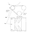
図3に示すように、そもそも加圧ローラには正クラウンをつけると、エンドレスベルトの両端部はテンションが緩く、波打ちやすくなるのは特許文献4の通りである。 As shown in FIG. 3, as shown in Patent Document 4, when the pressure roller is provided with a positive crown, the end portions of the endless belt are loosely tensioned and easily waved.
図4(a)に示すように、加圧ローラの回転速度をω、加圧ローラ周上でのエンドレスベ
ルトの移動距離を加圧ローラの長手中央でLc、端部でLeとする。加圧ローラには正クラウンがついているためLc>Leとなる。しかし、実際にはベルトは剛性のあるエンドレスベ
ルトのため加圧ローラ端部の移動距離はLes(=Lc)となる。つまり、Le→Lesとなるように
加圧ローラとエンドレスベルトが端部で滑っているか、あるいは定着ローラとエンドレスベルトが端部で滑っていることになる。
As shown in FIG. 4 (a), the rotational speed of the pressure roller is ω, the moving distance of the endless belt on the circumference of the pressure roller is Lc at the longitudinal center of the pressure roller, and Le at the end. Since the pressure roller has a positive crown, Lc> Le. However, since the belt is actually a rigid endless belt, the moving distance of the end portion of the pressure roller is Les (= Lc). That is, the pressure roller and the endless belt slide at the end so that Le → Les, or the fixing roller and the endless belt slide at the end.
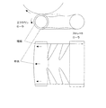
または逆に、図4(b)に示すように、Lc→Lcsとなるように加圧ローラとエンドレスベルトが中央部で滑っているか、あるいは定着ローラとエンドレスベルトが中央部で滑っていることも考えられる。 Or, conversely, as shown in FIG. 4 (b), the pressure roller and the endless belt may slip in the center so that Lc → Lcs, or the fixing roller and the endless belt may slip in the center. Conceivable.
しかし、この現象は軸方向で両端部に対して中央の直径が大きい加圧ローラ56をエンドレスベルト52を介して定着ローラ51に圧接していること自体で発生しており、ローラ55、57とは関係なく発生する。このようにローラ57をテンションローラとしテンションを上げたり、ローラ55、57に逆クラウンをつけて補正したとしてもエンドレスベルトの波打ちを解消することは出来ない。
However, this phenomenon occurs because the
ベルトの波打ちを解消しようとして、エンドレスベルトと加圧ローラを滑らせてしまうと、エンドレスベルト自体がスリップしてしまうことが容易に推測できる。 If the endless belt and the pressure roller are slid in an attempt to eliminate the undulation of the belt, it can be easily estimated that the endless belt itself slips.
そこで、本発明では、上記エンドレスベルトの波打ちを解決するとともに、同時にエンドレスベルトのスリップも発生しないことを目的としている。 Accordingly, an object of the present invention is to solve the undulation of the endless belt and to prevent the endless belt from slipping at the same time.
上記課題を解決するために、本発明は、記録材上の画像を定着する定着回転体と、前記定着回転体との間で定着ニップを形成するエンドレスベルトと、前記定着ニップにおいて前記エンドレスベルトを前記定着回転体に向けて加圧する加圧パッドと、前記エンドレスベルトを懸け回し、記録材を前記定着回転体から分離する分離部を形成し、回転軸方向の中央部が回転軸方向の両端部よりも太い形状とされた加圧ローラと、を有する定着装置において、前記定着回転体と前記エンドレスベルト外周面間の静止摩擦係数をμ1、前記加圧ローラと前記エンドレスベルトの内周面間の動摩擦係数をμ2、前記加圧パッドと前記エンドレスベルト内周面間の動摩擦係数をμ3、前記加圧ローラの前記定着回転体への加圧力をN1、前記加圧パッドの前記定着回転体への加圧力をN2、前記定着回転体の周速をV1、前記加圧ローラの周速をV2とすると、F1=μ1・(N1+N2)、F2=μ2・N1、F3=μ3・N2、F1−F3>|F2|、V1<V2を満足することを特徴とする。 In order to solve the above problems, the present invention provides a fixing rotator for fixing an image on a recording material, an endless belt for forming a fixing nip between the fixing rotator, and the endless belt in the fixing nip. A pressure pad for pressing toward the fixing rotator, and a separation part for suspending the endless belt and separating the recording material from the fixing rotator are formed. A fixing roller having a thicker pressure roller, the static friction coefficient between the fixing rotating body and the outer peripheral surface of the endless belt is μ1, and between the pressure roller and the inner peripheral surface of the endless belt. The dynamic friction coefficient is μ2, the dynamic friction coefficient between the pressure pad and the inner peripheral surface of the endless belt is μ3, the pressing force of the pressure roller to the fixing rotator is N1, and the pressure pad The pressure applied to the fixing rotator N2, the peripheral speed of the fixing rotator V1, when the peripheral speed of the pressure roller and V2, F1 = μ1 · (N1 + N2), F2 = μ2 · N1, F3 = μ3 N2, F1-F3> | F2 |, and V1 <V2 are satisfied.
また、前記ベルト内面に潤滑剤を塗布する塗布手段を有するようにしてもよい。 Moreover, you may make it have an application means which apply | coats a lubricant to the said belt inner surface.
また、前記加圧ローラの表面粗さRzは5μm以下であることが好適である。 The surface roughness Rz of the pressure roller is preferably 5 μm or less.
以上説明したように、本願発明に係る定着装置では、前記定着回転体と前記ベルト外周面間の静止摩擦係数をμ1、前記加圧ローラと前記ベルト内周面間の動摩擦係数をμ2、前記加圧パッドと前記ベルト内周面間の動摩擦係数をμ3、前記加圧ローラの前記定着回転
体への加圧力をN1、前記加圧パッドの前記定着回転体への加圧力をN2、前記定着回転体の周速をV1、前記加圧ローラの周速をV2とすると、F1=μ1・N1、F2=μ2・N1、F3=μ3・N2、F1-F3>|F2|、V1<V2とすることによって、定着ローラと加圧
ローラに挟まれたエンドレスベルトの長手の速度が定着ローラと周速差をもたずに密着して搬送され定着ローラの速度にならうように、かつ、加圧ローラとは滑りながら加圧ローラの長手の周速差の影響を受けないように構成し、エンドレスベルトの長手の周速差を解消することで波打ちを防止するものである。さらには、加圧パッドとエンドエスベルトの摩擦係数をさらに小さくすることでエンドレスベルトのスリップを防止するものである。
As described above, in the fixing device according to the present invention, the static friction coefficient between the fixing rotator and the belt outer peripheral surface is μ1, the dynamic friction coefficient between the pressure roller and the belt inner peripheral surface is μ2, and the addition The dynamic friction coefficient between the pressure pad and the inner peripheral surface of the belt is μ3, the pressing force of the pressure roller to the fixing rotator is N1, the pressing force of the pressure pad to the fixing rotator is N2, and the fixing rotation When the peripheral speed of the body is V1 and the peripheral speed of the pressure roller is V2, F1 = μ1 · N1, F2 = μ2 · N1, F3 = μ3 · N2, F1-F3> | F2 |, V1 <V2. Therefore, the longitudinal speed of the endless belt sandwiched between the fixing roller and the pressure roller is closely conveyed with the fixing roller without any difference in peripheral speed, and the speed of the fixing roller is followed. It is designed so that it is not affected by the circumferential speed difference of the pressure roller while sliding with the roller. And it is intended to prevent the undulation by eliminating the peripheral speed difference between the length of the endless belt. Furthermore, the slip of the endless belt is prevented by further reducing the coefficient of friction between the pressure pad and the end belt.
また、この摩擦係数の関係を実現するために、離型剤を有するトナーを用いれば定着ローラ上の離型剤塗布装置を不要となる。シリコーンオイル等を塗布する離型剤塗布装置があると定着ローラとエンドレスベルトの間の摩擦係数を下げてしまう。さらに、エンドレスベルト内部にもシリコーンオイル等の潤滑剤を塗布してしまうと、エンドレスベルトの回転駆動は定着ローラから受ける力も分離ローラから受ける力も不安定となりスリップが起きやすくなってしまう。離型剤を有するトナーを用いることで定着ローラに離型剤塗布装置を不用とすることで、エンドレスベルトの駆動は定着ローラから安定して受けることが出来るようになる。そのために、定着ローラ表層およびエンドレスベルトの表層にフッ素等の樹脂層を設けるほうが良い場合がある。 Further, if a toner having a release agent is used in order to realize the relationship of the friction coefficient, a release agent coating device on the fixing roller becomes unnecessary. If there is a release agent application device for applying silicone oil or the like, the friction coefficient between the fixing roller and the endless belt is lowered. Furthermore, if a lubricant such as silicone oil is applied to the inside of the endless belt, both the force received from the fixing roller and the force received from the separation roller are unstable during the rotational driving of the endless belt, and slipping tends to occur. By using a toner having a release agent, a release agent coating device is not required for the fixing roller, so that the driving of the endless belt can be stably received from the fixing roller. For this reason, it may be better to provide a resin layer such as fluorine on the surface layer of the fixing roller and the endless belt.
また、定着ローラとエンドレスベルト外面の摩擦係数よりも、エンドレスベルト内面と加圧ローラの摩擦係数を小さくするために、加圧ローラの表面の表面粗さを5μm以下と小さくしている。加圧ローラ表面の表面粗さを大きくするとエンドレスベルトとの摩擦係数が大きくなってしまい、波打ちが悪化してしまうからである。エンドレスベルト内面に潤滑剤を塗布することで波打ちはより解消しやすくなる。 Further, in order to make the friction coefficient between the inner surface of the endless belt and the pressure roller smaller than the friction coefficient between the fixing roller and the outer surface of the endless belt, the surface roughness of the surface of the pressure roller is set to 5 μm or less. This is because if the surface roughness of the pressure roller surface is increased, the coefficient of friction with the endless belt increases, and the waviness deteriorates. By applying a lubricant to the inner surface of the endless belt, waviness can be more easily eliminated.
また、定着ローラではなく熱源を有する定着回転体として定着ベルトを用いたほうが、より幅広い定着ニップ幅を得ることでき、定着装置の小型化に有利な場合もある。 In addition, if the fixing belt is used as a fixing rotating body having a heat source instead of a fixing roller, a wider fixing nip width can be obtained, which may be advantageous for downsizing the fixing device.
以下に、実施例を挙げて、本発明をより具体的に説明する。なお、これら実施例は、本発明における最良の実施の形態の一例ではあるものの、本発明はこれら実施例により限定されるものではない。 Hereinafter, the present invention will be described more specifically with reference to examples. Although these examples are examples of the best mode of the present invention, the present invention is not limited to these examples.
<第一の定着装置>
図2により本発明にかかる定着装置1を説明する。なお、次の説明では前出の部材と同一の部材には同一の符号を付してある。
<First fixing device>
The fixing
図2で、定着ローラ51は、内径φ37.8、外径φ38.4の0.3mm厚みのFeからなる芯金
上に、シリコーンゴムを0.5mm成形し、さらにその表面に30μm厚みのPFAチューブを被覆した外径φ40の長手方向にストレート形状の定着ローラを用いた。
In FIG. 2, the fixing
定着ベルト(または「エンドレスベルト」と称する)52は、厚み100μmポリイミド
基層にシリコーンゴム層を厚み0.5mmで被覆した外径φ90のシームレスベルトを用いた
。定着ベルト52は、入口ローラ55、分離ローラ56、テンションローラ57の3本のローラに張架させた。入口ローラ55は定着器の入口のローラであり記録材が侵入してくる所であり記録材の搬送路を変更しないよう固定されている。テンションローラ57は定着ベルト52にテンションを与えるようバネ付勢されている。
The fixing belt (or “endless belt”) 52 used was a seamless belt having an outer diameter of φ90, in which a silicone rubber layer was coated with a thickness of 0.5 mm on a polyimide base layer having a thickness of 100 μm. The fixing
分離ローラ56はSUSの中実ローラでエンドレスベルト52を介して定着ローラ51に
食い込むように加圧することにより定着ローラ51の弾性体を変形させ転写紙Pを定着ローラ51表面から分離している。本例では長手方向の中央部で外径φ15.5mm、両端部で15.0mmの正クラウン500μmとし、総圧50kgの加圧を行なった。分離ローラは定着ローラおよびエンドレスベルトと周速がほぼ同等となるように不図示の駆動源から回転駆動されている。
The
圧力付与部材100は、厚さ5mmのステンレス鋼製のベースプレート102の表面に
、ゴム硬度Hs30°のシリコーンゴムからなる弾性層101とPTFEをコーティングしたガラスクロスシートからなる低摩擦層103を積層して形成した。また、圧力付与部材100は、ベースプレート102側に配置された不図示のバネによって定着ローラ51に向けて押圧されている。
The
本例では、圧力付与部材に総圧N2=50kgの加圧を行った。このため圧力付与部材60kgと分離ローラN1=50kgで総圧100kgの加圧力となる。 In this example, the pressure application member was pressurized to a total pressure N2 = 50 kg. For this reason, when the pressure applying member 60 kg and the separation roller N1 = 50 kg, the total pressure is 100 kg.
潤滑剤塗布装置104としては、耐熱性の不織布を用い、潤滑材としてシリコーンオイルを塗布している。
As the
定着ローラのプロセススピード(周速度)は300mm/sec、分離ローラの周速度は310mm/sec とした。 The process speed (circumferential speed) of the fixing roller was 300 mm / sec, and the peripheral speed of the separation roller was 310 mm / sec.
<第二の定着装置>
図6により本発明にかかる定着装置21を説明する。なお、次の説明では前出の部材と同一の部材には同一の符号を付してあり、同一のものを使用しているので説明は省略する。
<Second fixing device>
The fixing
第二のエンドレスベルト105は、エンドレスベルト52と同じものを用いた。本第二の定着装置の定着ローラ51のみ弾性層および表層のない芯金のみのものを用いた。
The second
<摩擦係数>
本発明者の検討の比較例として、第一および第二の定着装置に対して、潤滑剤塗布装置を外した物、分離ローラの表面粗さRzを1μm、5μm、10μmとふった物、低磨耗層
104がない圧力付与部材を用いた。
<Friction coefficient>
As a comparative example for examination by the present inventors, the first and second fixing devices were removed from the lubricant application device, the separation roller surface roughness Rz was 1 μm, 5 μm, 10 μm, and the low A pressure applying member having no
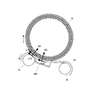
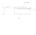
摩擦係数の測定は、図7に示すように、170℃に温調したホットプレート107の上にエンドレスベルトを切り開いたものを表または裏にして置き、その上に定着ローラ51または分離ローラ56または圧力付与部材100を置いて行う。この状態で、図中矢印方向へフォースゲージ108を繋げて引っ張り、動き出したときの力を読み取って静止摩擦
係数を算出し、動き出した後の力を読み取って動摩擦係数を算出した。エンドレスベルト52と分離ローラ56または圧力付与部材100の間に潤滑剤の塗布有りと無しの場合についても測定した。摩擦係数は図1のように、定着ローラ表面とエンドレスベルト外周面間の静止摩擦係数をμ1、分離ローラとエンドレスベルト内周面間の動摩擦係数をμ2、圧力付与部材とエンドレスベルト内周面間の動摩擦係数をμ3とした。
As shown in FIG. 7, the friction coefficient is measured by placing an endless belt cut open on the
この摩擦係数μ1、μ2、μ3と、分離ローラと圧力付与部材の加圧力N1、N2から、F1、F2、F3を以下のように定義する。すなわち、図8(a)のように定着ローラがエンドレスベルトを駆動する力をF1=μ1・(N1+N2)と定義する。そして、分離ローラが
エンドレスベルトを駆動する力をF2=μ2・N1と定義する。さらに、圧力付与部材がエンドレスベルトと摺擦してエンドレスベルトを止めようとする力をF3=μ3・N2を定義する
。
F1, F2, and F3 are defined as follows from the friction coefficients μ1, μ2, and μ3 and the applied pressures N1 and N2 of the separation roller and the pressure applying member. That is, as shown in FIG. 8A, the force by which the fixing roller drives the endless belt is defined as F1 = μ1 · (N1 + N2). The force with which the separation roller drives the endless belt is defined as F2 = μ2 · N1. Further, F3 = μ3 · N2 is defined as a force for the pressure applying member to rub against the endless belt to stop the endless belt.
以上説明した第一および第二の定着装置で以下のような比較実験を行った。 The following comparative experiments were conducted with the first and second fixing devices described above.
定着条件は、定着ローラの表面温度を170℃に温調とした。通紙する記録材および未定
着トナーの条件は、普通紙64g/m2、に未定着のベタ画像をのせて定着した。
The fixing conditions were such that the surface temperature of the fixing roller was adjusted to 170 ° C. The conditions for the recording material to be passed and the unfixed toner were fixed by placing an unfixed solid image on plain paper 64 g / m 2 .
第一および第二の定着装置での、各条件での摩擦係数μ1、μ2、μ3、エンドレスベルトの波打ちおよびベタ画像の擦れ跡、ベルトスリップは表1のような結果となった。 Tables 1 and 2 show friction coefficients μ1, μ2, and μ3, endless belt undulations, solid image rubbing traces, and belt slip in the first and second fixing devices.

ベルト波打ち/画像擦れ、ベルトスリップ欄
〇:ベルトの波打ち、画像の擦れ跡が無い。
または、ベルトスリップによる画像ずれが無い。
△:ベルトの波打ち、画像の擦れ跡が軽微に有る。
×:ベルトの波打ち、画像の擦れ跡が有る。
または、ベルトスリップによる画像ずれが有る
-:ベルトスリップによる画像ずれがあり、
ベルトの波打ち、画像の擦れ跡が有るかどうか分からない。
判定欄
OK:F1-F3>|F2|
N:F1-F3<F2
S:F1-F3<-F2 ( F1+F2<F3 )
Belt waving / image rubbing, belt slip column ◯: No belt waving, image rubbing trace.
Or, there is no image shift due to belt slip.
Δ: There are slight undulations of the belt and rubbing traces of the image.
X: There is a wave of the belt and a rubbing trace of the image.
Or there is image shift due to belt slip
-: There is image shift due to belt slip,
I don't know if there are wavy belts or rubbing marks on the image.
Judgment column
OK: F1-F3> | F2 |
N: F1-F3 <F2
S: F1-F3 <-F2 (F1 + F2 <F3)
表1の比較例5、6の結果よりベルトのスリップが発生しているのはF1-F3<-F2(判定S)のときであることが分かる。これは、図8(a)でF1+F2<F3となっている場合で、エン
ドレスベルトの駆動力がブレーキ力に負けてしまっている状態である。
From the results of Comparative Examples 5 and 6 in Table 1, it can be seen that the belt slip occurs when F1-F3 <-F2 (determination S). This is a case where F1 + F2 <F3 in FIG. 8A, and the driving force of the endless belt has lost the braking force.
表1の実施例1、2および比較例1〜4の結果より、分離ローラの表面粗さを小さくしたほうが良いことが分かる。また、実施例1および比較例2、5、6の結果より、潤滑剤を塗布しないよりも塗布したほうが良く、圧力付与部材表層にフッ素コートをしないよりもしたほうが良いことが分かる。この場合、ベルトの波打ちおよび画像擦れが発生しているのは、F1-F3<F2(判定N)ときであることがわかる。つまり、図8(a)でF1<F2+F3となっている場合で、エンドレスベルトが分離ローラの駆動力で回転してしまい、定着ローラとエンドレスベルトが滑ってしまっている状態である。 From the results of Examples 1 and 2 and Comparative Examples 1 to 4 in Table 1, it can be seen that it is better to reduce the surface roughness of the separation roller. Moreover, from the results of Example 1 and Comparative Examples 2, 5, and 6, it can be seen that it is better to apply the lubricant than not to apply the lubricant, and it is better to not apply the fluorine coating to the surface of the pressure applying member. In this case, it can be seen that the waviness of the belt and image blurring occur when F1-F3 <F2 (determination N). That is, in the case of F1 <F2 + F3 in FIG. 8A, the endless belt is rotated by the driving force of the separation roller, and the fixing roller and the endless belt are slipping.
表1の実施例1、2および3は、F1-F3>|F2|(判定OK)であるが、つまり、F1-F3>F2かつF1-F3>-F2の場合で、上記ベルトのスリップも波打ちも発生しない状態である。つまり、エンドレスベルトは、F1+F2>F3(F1-F3>-F2)の関係より定着ローラおよび分離
ローラからの駆動が、圧力付与部材からのブレ−キ力よりも勝っているのでスリップしない。加えて、F1>F2+F3(F1-F3>F2)の関係より、エンドレスベルトの定着ローラからの駆動力が、ベルト内面の駆動力よりも勝っている。したがって、エンドレスベルトの速度が定着ローラの速度にならっている状態で、前述したようにエンドレスベルトの長手に速度差を生じベルトの波打ちが発生していると考えられる。
Examples 1, 2 and 3 in Table 1 are F1-F3> | F2 | (determination OK), that is, in the case of F1-F3> F2 and F1-F3> -F2, the slip of the belt is also In this state, no undulation occurs. That is, the endless belt does not slip because the drive from the fixing roller and the separation roller is superior to the brake force from the pressure applying member because of the relationship of F1 + F2> F3 (F1-F3> −F2). In addition, from the relationship of F1> F2 + F3 (F1-F3> F2), the driving force from the fixing roller of the endless belt is superior to the driving force of the inner surface of the belt. Therefore, it is considered that the wavyness of the belt is generated due to a speed difference in the length of the endless belt as described above in a state where the speed of the endless belt is equal to the speed of the fixing roller.
また、分離ローラは回転駆動をやめ、エンドレスベルトに従動回転とすると表1でスリップしていなかった場合でもスリップが発生してしまった。また、分離ローラを回転駆動し、周速度を300mm/sec未満にしてしまうと、やはりスリップが発生してしまった。この
場合、図8(b)のように、分離ローラがエンドレスベルトを駆動する力F2が、エンドレス
ベルトの回転方向と逆向きにかかってしまい、駆動力ではなく、ブレーキ力になってしまっていると考えられる。
In addition, when the separation roller stopped rotating and was driven to rotate by the endless belt, slip occurred even if it did not slip in Table 1. Further, when the separation roller was driven to rotate and the peripheral speed was reduced to less than 300 mm / sec, slipping occurred again. In this case, as shown in FIG. 8B, the force F2 at which the separation roller drives the endless belt is applied in the direction opposite to the rotation direction of the endless belt, and the braking force is generated instead of the driving force. it is conceivable that.
この結果から、分離ローラはエンドレスベルトと周速差をもちつつ(滑りつつ)、動摩擦によってエンドレスベルトの回転駆動の補助をしていると考えられる。 From this result, it is considered that the separation roller assists the rotational drive of the endless belt by dynamic friction while having a circumferential speed difference (sliding) with the endless belt.
以上のように、F1-F3>|F2|の関係とすることで、エンドレスベルトのスリップ、波
打ちおよび画像擦れを防止することができる。
As described above, by satisfying the relationship of F1-F3> | F2 |, it is possible to prevent the endless belt from slipping, wavy and image blurring.
また、エンドレスベルトと分離ローラを滑りやすくすることで、エンドレスベルトの寄り制御にも有利となっている。ローラ57を寄り制御ローラとした場合、ローラ57はエンドレスベルトの長手方向の位置に応じて角度を振ってエンドレスベルトが長手中央に寄
るように移動する。その場合、寄り制御ローラ57による寄り力に対して、前記μ2およびμ3はブレーキ力となるため、エンドレスベルトと分離ローラを滑りやすくすることで、寄り力が効きやすくなり、エンドレスベルトの寄り制御にも有利となることがわかる。
In addition, by making the endless belt and the separation roller easy to slide, it is advantageous for endless belt shift control. In the case where the
また、本例では3本のローラに掛けまわすエンドレスベルトに関して説明したが、分離ローラおよび圧力付与部材があれば、2本のローラに掛けまわすタイプや、分離ローラと圧力付与部材のみのタイプであってもよい。 Further, in this example, the endless belt that is wound around three rollers has been described. However, if there are a separation roller and a pressure applying member, the belt can be wound around two rollers or only the separation roller and the pressure applying member. May be.
なお、本発明の定着装置は、上述したような記録材に形成された未定着トナー像を定着する用途に限られない。すなわち、本発明の定着装置は、記録材に形成される画像の光沢度を向上させるために、トナー像を仮定着するような用途や、既に仮定着されたトナー像を再加熱して光沢度を向上させる用途としても使用できる。本例ではこれらを総称して定着装置と呼ぶことにする。 The fixing device of the present invention is not limited to the use for fixing the unfixed toner image formed on the recording material as described above. In other words, the fixing device of the present invention is used for the purpose of assuming a toner image in order to improve the glossiness of an image formed on a recording material, or by reheating a toner image that has already been assumed. It can also be used as an application to improve the quality. In this example, these are collectively referred to as a fixing device.
<画像形成装置>
図9により本発明の実施例に係る定着装置を備えた画像形成装置の全体構成について説明する。
<Image forming apparatus>
The overall configuration of the image forming apparatus including the fixing device according to the embodiment of the present invention will be described with reference to FIG.
図9に示す装置内には、画像形成手段を構成する第1、第2、第3、第4の画像形成部Pa、Pb、Pc、Pdが併設され、各々異なった色のトナー像が潜像、現像、転写のプロセスを経て形成される。 In the apparatus shown in FIG. 9, first, second, third, and fourth image forming portions Pa, Pb, Pc, and Pd constituting the image forming means are provided together, and toner images of different colors are latent in each. Formed through image, development and transfer processes.
画像形成部Pa、Pb、Pc、Pdは、それぞれ専用の像担持体、本例では電子写真感光ドラム303a、303b、303c、303dを具備し、各感光ドラム303a、303b、303c、303d上に各色のトナー像が形成される。各感光ドラム303a、303b、303c、303dに隣接して中間転写体1130が設置される。感光ドラム303a、303b、303c、303d上に形成された各色のトナー像は、中間転写体330上に1次転写され、2次転写部で記録材p上に転写される。さらにトナー像が転写された記録材pは、定着装置1で加熱及び加圧によりトナー像を定着した後、記録画像として装置外に排出される。
Each of the image forming portions Pa, Pb, Pc, and Pd includes a dedicated image carrier, in this example, electrophotographic
感光ドラム303a〜dの外周には、それぞれドラム帯電器302a〜d、現像器301a〜d、1次転写帯電器324a〜d及びクリーナ304a〜dが設けられる。装置の上方部にはさらに図示しない光源装置およびポリゴンミラーが設置されている。
光源装置から発せられたレーザー光を、ポリゴンミラーを回転して走査し、その走査光の光束を反射ミラーによって偏向し、fθレンズにより感光ドラム303a、303b、
303c、303dの母線上に集光して露光する。これにより、感光ドラム303a、303b、303c、303d上に画像信号に応じた潜像が形成される。
The laser light emitted from the light source device is scanned by rotating the polygon mirror, the light beam of the scanning light is deflected by the reflection mirror, and the photosensitive drums 303a, 303b,
The light is condensed and exposed on the
現像器301a、301b、301c、301dには、現像剤としてそれぞれイエロー、マゼンタ、シアン及びブラックのトナーが、図示しない供給装置により所定量充填されている。現像器301a、301b、301c、301dは、それぞれ感光ドラム303a、303b、303c、303d上の潜像を現像して、シアントナー像、マゼンタトナー像、イエロートナー像及びブラックトナー像として可視化する。
The developing devices 301a, 301b, 301c, and 301d are filled with predetermined amounts of yellow, magenta, cyan, and black toners as developers, respectively, by a supply device (not shown). The developing devices 301a, 301b, 301c, and 301d develop the latent images on the
中間転写体330は矢示の方向に感光ドラム303と同じ周速度をもって回転駆動されている。
The
感光ドラム303a上に形成担持された上記第1色のイエロートナー画像は、感光ドラ
ム3と中間転写体330とのニップ部を通過する。この過程で、中間転写体330に印加される1次転写バイアスにより形成される電界と圧力により、中間転写体330の外周面に中間転写されていく。
The first color yellow toner image formed and supported on the photosensitive drum 303 a passes through the nip portion between the
同様に第2色のマゼンタトナー画像、第3色のシアントナー画像、第4色のブラックトナー画像が順次中間転写体330上に重畳転写され、目的のカラー画像に対応した合成カラートナー画像が形成される。
Similarly, a magenta toner image of the second color, a cyan toner image of the third color, and a black toner image of the fourth color are sequentially superimposed and transferred onto the
311は2次転写ローラを示し、中間転写体330に対応し平行に軸受させて下面部に接触させて配設してある。2次転写ローラ311には、2次転写バイアス源によって所望の2次転写バイアスが印加されている。中間転写体330上に重畳転写された合成カラートナー画像の記録材Pへの転写は、次のように行われる。すなわち、給紙カセット300からレジストローラ312、転写前ガイドを通過して中間転写体330と2次転写ローラ311との当接ニップに所定のタイミングで記録材Pが給送される。これと同時に2次転写バイアスがバイアス電源からに印加される。この2次転写バイアスにより中間転写体330から記録材Pへ合成カラートナー画像が転写される。
一次転写が終了した感光ドラム303a、303b、303c、303dは、それぞれのクリーナ304a、304b、304c、304dにより転写残トナーをクリーニング、除去され、引き続き次の潜像の形成以下に備えられる。中間転写体330上に残留したトナー及びその他の異物は、中間転写体330の表面にクリーニングウエブ(不織布)を当接して、拭い取るようにしている。
The
トナー画像の転写を受けた転写材Pは定着装置1又は21へ順次導入され、転写材に熱と圧力を加えることで定着された後に排紙部363を経て出力される。
The transfer material P that has received the transfer of the toner image is sequentially introduced into the fixing
1,21:定着装置
51:定着ローラ
52:定着ベルト(エンドレスベルト)
56:分離ローラ
58:ハロゲンヒータ
100:圧力付与部材
P:記録材
1, 21: Fixing device 51: Fixing roller 52: Fixing belt (endless belt)
56: Separation roller 58: Halogen heater 100: Pressure applying member P: Recording material
Claims (3)
前記定着回転体との間で定着ニップを形成するエンドレスベルトと、
前記定着ニップにおいて前記エンドレスベルトを前記定着回転体に向けて加圧する加圧パッドと、
前記エンドレスベルトを懸け回し、記録材を前記定着回転体から分離する分離部を形成し、回転軸方向の中央部が回転軸方向の両端部よりも太い形状とされた加圧ローラと、を有する定着装置において、
前記定着回転体と前記エンドレスベルト外周面間の静止摩擦係数をμ1、前記加圧ローラと前記エンドレスベルトの内周面間の動摩擦係数をμ2、前記加圧パッドと前記エンドレスベルト内周面間の動摩擦係数をμ3、前記加圧ローラの前記定着回転体への加圧力をN1、前記加圧パッドの前記定着回転体への加圧力をN2、前記定着回転体の周速をV1、前記加圧ローラの周速をV2とすると、
F1=μ1・(N1+N2)、
F2=μ2・N1、
F3=μ3・N2、
F1−F3>|F2|、
V1<V2
を満足することを特徴とする定着装置。 A fixing rotator for fixing the image on the recording material;
An endless belt forming a fixing nip with the fixing rotating body;
A pressure pad for pressing the endless belt toward the fixing rotator at the fixing nip;
A pressure roller that hangs around the endless belt, forms a separation unit that separates the recording material from the fixing rotator, and has a central portion in the rotation axis direction thicker than both end portions in the rotation axis direction; In the fixing device,
The coefficient of static friction between the fixing rotator and the outer peripheral surface of the endless belt is μ1, the coefficient of dynamic friction between the pressure roller and the inner peripheral surface of the endless belt is μ2, and the pressure pad and the inner peripheral surface of the endless belt are The dynamic friction coefficient is μ3, the pressing force of the pressure roller to the fixing rotator is N1, the pressing force of the pressure pad to the fixing rotator is N2, the peripheral speed of the fixing rotator is V1, and the pressing force If the peripheral speed of the roller is V2,
F1 = μ1 · ( N1 + N2) ,
F2 = μ2 · N1,
F3 = μ3 · N2,
F1-F3> | F2 |,
V1 <V2
A fixing device satisfying the requirements.
Priority Applications (3)
| Application Number | Priority Date | Filing Date | Title |
|---|---|---|---|
| JP2005266009A JP4878464B2 (en) | 2005-09-13 | 2005-09-13 | Fixing device |
| US11/530,769 US7392005B2 (en) | 2005-09-13 | 2006-09-11 | Image heating apparatus |
| EP06254739A EP1762912B1 (en) | 2005-09-13 | 2006-09-12 | Image heating apparatus |
Applications Claiming Priority (1)
| Application Number | Priority Date | Filing Date | Title |
|---|---|---|---|
| JP2005266009A JP4878464B2 (en) | 2005-09-13 | 2005-09-13 | Fixing device |
Publications (3)
| Publication Number | Publication Date |
|---|---|
| JP2007079049A JP2007079049A (en) | 2007-03-29 |
| JP2007079049A5 JP2007079049A5 (en) | 2008-10-23 |
| JP4878464B2 true JP4878464B2 (en) | 2012-02-15 |
Family
ID=37939447
Family Applications (1)
| Application Number | Title | Priority Date | Filing Date |
|---|---|---|---|
| JP2005266009A Expired - Fee Related JP4878464B2 (en) | 2005-09-13 | 2005-09-13 | Fixing device |
Country Status (1)
| Country | Link |
|---|---|
| JP (1) | JP4878464B2 (en) |
Families Citing this family (2)
| Publication number | Priority date | Publication date | Assignee | Title |
|---|---|---|---|---|
| US8331841B2 (en) | 2008-08-29 | 2012-12-11 | Konica Minolta Business Technologies, Inc. | Fixing device and image forming apparatus |
| JP5375729B2 (en) * | 2010-04-16 | 2013-12-25 | コニカミノルタ株式会社 | Fixing apparatus and image forming apparatus |
Family Cites Families (8)
| Publication number | Priority date | Publication date | Assignee | Title |
|---|---|---|---|---|
| JPH11231702A (en) * | 1998-02-17 | 1999-08-27 | Fuji Xerox Co Ltd | Fixing device |
| JP2001201979A (en) * | 2000-01-20 | 2001-07-27 | Fuji Xerox Co Ltd | Image fixing device |
| JP2002189379A (en) * | 2000-12-22 | 2002-07-05 | Oki Data Corp | Fixing device |
| JP2004279492A (en) * | 2003-03-13 | 2004-10-07 | Konica Minolta Holdings Inc | Image forming apparatus |
| JP4493418B2 (en) * | 2003-06-20 | 2010-06-30 | 株式会社リコー | Belt fixing device |
| JP2005017482A (en) * | 2003-06-24 | 2005-01-20 | Ricoh Co Ltd | Fixing apparatus and image forming apparatus |
| JP2005128337A (en) * | 2003-10-24 | 2005-05-19 | Sharp Corp | Fixing apparatus and image forming apparatus having the same |
| JP2005134646A (en) * | 2003-10-30 | 2005-05-26 | Oki Data Corp | Fixing apparatus and fixing control method |
-
2005
- 2005-09-13 JP JP2005266009A patent/JP4878464B2/en not_active Expired - Fee Related
Also Published As
| Publication number | Publication date |
|---|---|
| JP2007079049A (en) | 2007-03-29 |
Similar Documents
| Publication | Publication Date | Title |
|---|---|---|
| CN100533305C (en) | Image heating equipment | |
| CN102023544A (en) | Fixing device and image forming apparatus employing the fixing device | |
| JP2004226819A (en) | Heating device and image forming device | |
| JP5119774B2 (en) | Belt fixing device and image forming apparatus | |
| JP4347309B2 (en) | Fixing apparatus, image forming apparatus, and method for setting length of endless belt provided in fixing apparatus | |
| JP5034874B2 (en) | Fixing device | |
| US7392005B2 (en) | Image heating apparatus | |
| JP2010204587A (en) | Fixing device, image forming apparatus and endless belt for fixing | |
| JP2019184759A (en) | Fixing device and image forming apparatus | |
| JP5282292B2 (en) | Roller, belt fixing device and image forming apparatus | |
| JP4878464B2 (en) | Fixing device | |
| JP2006243497A (en) | Fixing device | |
| JP4973648B2 (en) | Fixing apparatus and image forming apparatus having the same | |
| JP5268423B2 (en) | Image heating device | |
| JP4574180B2 (en) | Fixing apparatus and image forming apparatus | |
| JP5089083B2 (en) | Image heating device | |
| CN104076662B (en) | Fixing device and image forming apparatus | |
| JP2005055470A (en) | Endless fixing belt and fixing device | |
| JP2007256439A (en) | Image heating device | |
| JP2010191186A (en) | Fixing device and image forming apparatus | |
| JP2012027371A (en) | Image heating device | |
| JP2009109931A (en) | Fixing device | |
| JP2004198695A (en) | Image fixing device and image forming apparatus using the same | |
| JP2007079048A (en) | Image heating device | |
| JP2005071637A (en) | Heating apparatus and image forming apparatus |
Legal Events
| Date | Code | Title | Description |
|---|---|---|---|
| A521 | Request for written amendment filed |
Free format text: JAPANESE INTERMEDIATE CODE: A523 Effective date: 20080909 |
|
| A621 | Written request for application examination |
Free format text: JAPANESE INTERMEDIATE CODE: A621 Effective date: 20080909 |
|
| A977 | Report on retrieval |
Free format text: JAPANESE INTERMEDIATE CODE: A971007 Effective date: 20110330 |
|
| A131 | Notification of reasons for refusal |
Free format text: JAPANESE INTERMEDIATE CODE: A131 Effective date: 20110419 |
|
| A521 | Request for written amendment filed |
Free format text: JAPANESE INTERMEDIATE CODE: A523 Effective date: 20110620 |
|
| TRDD | Decision of grant or rejection written | ||
| A01 | Written decision to grant a patent or to grant a registration (utility model) |
Free format text: JAPANESE INTERMEDIATE CODE: A01 Effective date: 20111122 |
|
| A01 | Written decision to grant a patent or to grant a registration (utility model) |
Free format text: JAPANESE INTERMEDIATE CODE: A01 |
|
| A61 | First payment of annual fees (during grant procedure) |
Free format text: JAPANESE INTERMEDIATE CODE: A61 Effective date: 20111128 |
|
| R151 | Written notification of patent or utility model registration |
Ref document number: 4878464 Country of ref document: JP Free format text: JAPANESE INTERMEDIATE CODE: R151 |
|
| FPAY | Renewal fee payment (event date is renewal date of database) |
Free format text: PAYMENT UNTIL: 20141209 Year of fee payment: 3 |
|
| LAPS | Cancellation because of no payment of annual fees |