JP4875673B2 - Strainer for reactor containment - Google Patents
Strainer for reactor containment Download PDFInfo
- Publication number
- JP4875673B2 JP4875673B2 JP2008198739A JP2008198739A JP4875673B2 JP 4875673 B2 JP4875673 B2 JP 4875673B2 JP 2008198739 A JP2008198739 A JP 2008198739A JP 2008198739 A JP2008198739 A JP 2008198739A JP 4875673 B2 JP4875673 B2 JP 4875673B2
- Authority
- JP
- Japan
- Prior art keywords
- strainer
- coolant
- flow path
- pit
- floor
- Prior art date
- Legal status (The legal status is an assumption and is not a legal conclusion. Google has not performed a legal analysis and makes no representation as to the accuracy of the status listed.)
- Active
Links
- 239000002826 coolant Substances 0.000 claims description 175
- 238000001816 cooling Methods 0.000 claims description 34
- XLYOFNOQVPJJNP-UHFFFAOYSA-N water Substances O XLYOFNOQVPJJNP-UHFFFAOYSA-N 0.000 claims description 21
- 230000015572 biosynthetic process Effects 0.000 claims description 3
- 239000000126 substance Substances 0.000 claims description 3
- 238000005507 spraying Methods 0.000 description 20
- 239000007921 spray Substances 0.000 description 12
- 239000000463 material Substances 0.000 description 9
- 239000007788 liquid Substances 0.000 description 7
- 238000000034 method Methods 0.000 description 7
- 238000013461 design Methods 0.000 description 6
- 238000002347 injection Methods 0.000 description 6
- 239000007924 injection Substances 0.000 description 6
- 230000003014 reinforcing effect Effects 0.000 description 6
- 238000009434 installation Methods 0.000 description 5
- 238000010276 construction Methods 0.000 description 4
- 230000007257 malfunction Effects 0.000 description 3
- 238000010586 diagram Methods 0.000 description 2
- 238000001035 drying Methods 0.000 description 2
- 238000009415 formwork Methods 0.000 description 2
- 238000002955 isolation Methods 0.000 description 2
- 239000000203 mixture Substances 0.000 description 2
- 206010037660 Pyrexia Diseases 0.000 description 1
- 238000004891 communication Methods 0.000 description 1
- 239000000470 constituent Substances 0.000 description 1
- 238000007599 discharging Methods 0.000 description 1
- 239000006185 dispersion Substances 0.000 description 1
- 239000000446 fuel Substances 0.000 description 1
- 239000011810 insulating material Substances 0.000 description 1
- 238000012545 processing Methods 0.000 description 1
- 238000012360 testing method Methods 0.000 description 1
Images


Classifications
-
- Y—GENERAL TAGGING OF NEW TECHNOLOGICAL DEVELOPMENTS; GENERAL TAGGING OF CROSS-SECTIONAL TECHNOLOGIES SPANNING OVER SEVERAL SECTIONS OF THE IPC; TECHNICAL SUBJECTS COVERED BY FORMER USPC CROSS-REFERENCE ART COLLECTIONS [XRACs] AND DIGESTS
- Y02—TECHNOLOGIES OR APPLICATIONS FOR MITIGATION OR ADAPTATION AGAINST CLIMATE CHANGE
- Y02E—REDUCTION OF GREENHOUSE GAS [GHG] EMISSIONS, RELATED TO ENERGY GENERATION, TRANSMISSION OR DISTRIBUTION
- Y02E30/00—Energy generation of nuclear origin
- Y02E30/30—Nuclear fission reactors
Landscapes
- Structure Of Emergency Protection For Nuclear Reactors (AREA)
Description
この発明は、加圧水型原子炉を格納する格納容器内に収納される一次冷却系に注入される冷却材であって、一次冷却系から漏れ出た冷却材及び格納容器内に散布された冷却材を循環させる原子炉格納容器用ストレーナに関する。 The present invention relates to a coolant that is injected into a primary cooling system housed in a containment vessel that stores a pressurized water reactor, the coolant leaking from the primary cooling system, and the coolant sprayed into the containment vessel about the reactor containment vessel strainer for circulating.
従来、加圧水型原子炉を格納する格納容器内に、一次冷却系を冷却するために一次冷却系に冷却材を注入すると共に、格納容器設備を冷却する冷却材を格納容器の天井から散布する設備がある。例えば、特許文献1には、前記設備が前記冷却材を循環させる際に、冷却材に含まれる異物を取り除くストレーナの負担を低減させる方法及び装置が開示されている。 Conventionally, a coolant is injected into the primary cooling system in order to cool the primary cooling system into the containment vessel storing the pressurized water reactor, and the coolant for cooling the containment facility is sprayed from the ceiling of the containment vessel There is. For example, Patent Document 1 discloses a method and apparatus for reducing the strain on a strainer that removes foreign matters contained in a coolant when the facility circulates the coolant.
従来、ストレーナは、格納容器の床の基面よりも窪んで形成されるピットに納められている。ここで、近年、前記ストレーナは、異物を取り除く部分の面積の増加が求められている。 Conventionally, the strainer is housed in a pit formed to be recessed from the base surface of the storage container floor. Here, in recent years, the strainer has been required to increase the area of the portion from which foreign matter is removed.
前記ストレーナは、異物を取り除く部分の面積が増加するほど、目詰まりが抑制される。しかしながら、異物を取り除く部分の面積が増加すると、前記ストレーナは大型化する。よって、異物を取り除く部分の面積の増加量は、前記ピットの大きさに制限を受ける。 The strainer is suppressed from being clogged as the area of the portion from which foreign matter is removed increases. However, when the area of the part from which the foreign matter is removed increases, the strainer increases in size. Therefore, the amount of increase in the area where the foreign matter is removed is limited by the size of the pit.
本発明は、上記に鑑みてなされたものであって、ストレーナの部分であって、冷却材に含まれる異物を取り除く部分の面積を増加させることを目的とする。 This invention is made in view of the above, Comprising: It aims at increasing the area of the part which is a part of a strainer and removes the foreign material contained in a coolant.
上述した課題を解決し、目的を達成するために、本発明に係る原子炉格納容器用ストレーナは、加圧水型原子炉の一次冷却系から漏れ出た冷却材、及び前記加圧水型原子炉を収納する格納容器内に散布された冷却材に含まれる異物を除去する板状に形成されるディスクを複数積み重ねたストレーナモジュールと、前記格納容器の床の基面よりも窪んで形成され、前記ストレーナモジュールにより異物が除去された前記冷却材を溜めるピットと、前記格納容器の床と前記ストレーナモジュールとの間に設けられ、前記ピットを塞ぐと共に、前記ストレーナモジュールにより異物が除去された後の前記冷却材を前記ピットへ導く流路が形成された流路形成手段と、を備え、前記ピットを塞ぐ前記流路形成手段に前記ストレーナモジュールを配置し、前記流路形成手段は、枠型に形成された基礎であって、前記格納容器の天井から前記格納容器の床に向かって前記基礎を投影した枠内に、前記ストレーナモジュールにより前記異物が除去された前記冷却材を前記ストレーナモジュール内部のコアチューブに流れ込ませ、前記流路形成手段に導入するコアチューブ用開口部と前記ピットとを内包する枠型基礎と、前記枠型基礎の面のうち、前記床と反対側の面に取り付けられ、前記コアチューブ用開口部が形成されるボードと、を含んでいることを特徴とする。 To solve the above problems and achieve the object, the containment vessel for strainer according to the present invention is housed, the coolant leaked from the primary cooling system of a pressurized water reactor, and the pressurized water reactor a strainer modules stacked plurality of disks formed in a plate shape for removing foreign matters contained in the coolant is sprayed into the containment vessel to be formed to be recessed than the base surface of the floor of the containment, the strainer module The cooling material after the foreign material is removed by the strainer module is provided between the pit for storing the cooling material from which the foreign material has been removed by, and the storage container floor and the strainer module. A flow path forming means formed with a flow path for guiding the pit to the pit, and the strainer module is disposed in the flow path forming means for closing the pit. The flow path forming means is a foundation formed in a frame shape, and the foreign matter is removed by the strainer module in a frame in which the foundation is projected from a ceiling of the containment vessel toward a floor of the containment vessel. Further, the coolant flows into the core tube inside the strainer module, and the frame-type foundation including the core tube opening and the pit introduced into the flow path forming means, and among the surfaces of the frame-type foundation, the floor and mounted on the opposite side, a board opening for the core tube is formed, characterized Rukoto contain.
上記構成により、本発明に係る原子炉格納容器用ストレーナは、ピットを塞ぐ流路形成手段にストレーナモジュールを配置しているため、ストレーナモジュールがピット内部よりも広いピットの外部空間に配置され、冷却材に含まれる異物を取り除くストレーナモジュール部分の面積を増加させることができる。このストレーナモジュールによって異物が除去された冷却材は、流路形成手段を介してピットに導くことができる。流路形成手段は、枠型に形成された基礎であって、格納容器の天井から格納容器の床に向って基礎を投影した枠内に枠型基礎とボードとを含んで構成されている。このように、本発明に係る原子炉格納容器用ストレーナは、ボードが枠型基礎に取り付けられ、流路形成手段の内部を流れる異物が除去された冷却材が、異物を含む冷却材と混ざることを抑制しつつ、異物が除去された冷却材のピットまでの流路を確保することができる。 With the above structure, a containment vessel for strainer according to the present invention, since the arranged strainer module in the channel forming unit for closing a pit arranged in the outer space of the wider pits than the internal strainer module Gapi Tsu DOO is, it is possible to increase the area of the strainer module part for removing foreign matters contained in the coolant. The coolant from which foreign matter has been removed by the strainer module can be guided to the pits through the flow path forming means. The flow path forming means is a foundation formed in a frame shape, and includes a frame foundation and a board in a frame in which the foundation is projected from the ceiling of the storage container toward the floor of the storage container. Thus, in the reactor containment vessel strainer according to the present invention, the board is attached to the frame-type foundation, and the coolant from which the foreign matter flowing inside the flow path forming means is removed is mixed with the coolant containing the foreign matter. It is possible to secure a flow path to the pit of the coolant from which foreign matter has been removed while suppressing the above.
本発明の好ましい態様としては、前記ストレーナモジュールは、少なくとも一部が前記床の前記基面よりも鉛直方向上側に設けられていることが望ましい。 As a preferred aspect of the present invention, it is desirable that at least a part of the strainer module is provided above the base surface of the floor in the vertical direction.
一般的に、前記基面よりも鉛直方向上側の空間は、前記基面よりも鉛直方向下側の空間よりも広い。よって、原子炉格納容器用ストレーナのストレーナモジュールの少なくとも一部を、前記床の前記基面よりも、鉛直方向上側に設けることによって、異物を除去する部分の面積を増加することができる。 Generally, the space above the base surface in the vertical direction is wider than the space below the base surface in the vertical direction. Therefore, by providing at least a part of the strainer module of the reactor containment vessel strainer above the base surface of the floor in the vertical direction, it is possible to increase the area of the portion from which foreign matter is removed.
本発明の好ましい態様としては、前記ピットは、前記異物が除去された前記冷却材が排出される開口が形成される空間であって、前記ボードの少なくとも一部によって仕切られる空間であって、外部の異物を含む前記冷却材が存在する空間から仕切られる空間であることが望ましい。 As a preferred aspect of the present invention, the pit is a space in which an opening for discharging the coolant from which the foreign matter has been removed is formed, and is a space partitioned by at least a part of the board , It is desirable that the space is partitioned from the space where the coolant containing the foreign material exists.
これにより、原子炉格納容器用ストレーナは、ピットに溜められる冷却材であって異物が除去された冷却材が、異物を含む冷却材が混ざらずに前記開口から排出される。 Thus, the containment vessel for strainer, coolant foreign matter is removed by a coolant to be accumulated in the pits, Ru is discharged from the opening without mix is cooled material containing foreign matter.
本発明の好ましい態様としては、前記ストレーナモジュールは、前記床の前記基面よりも鉛直方向下側に設けられていることが望ましい。 As a preferred aspect of the present invention, it is desirable that the strainer module is provided on a lower side in the vertical direction than the base surface of the floor.
ここで、ストレーナモジュールが取り付けられる流路形成手段から格納容器内に溜まった冷却材の液面までの距離は、基面から前記液面までの距離よりも大きい。よって、原子炉格納容器用ストレーナは、異物を除去する部分の面積が向上する。 Here, the distance from the channel forming means strainer module is attached to the liquid surface of the accumulated coolant storage vessel, not greater than the distance from the base surface to the liquid surface. Thus, the containment vessel for strainer, increase the area of the portion to remove foreign matter.
本発明に係る原子炉格納容器用ストレーナは、ストレーナの部分であって、冷却材に含まれる異物を取り除く部分の面積を増加させることを目的とする。 Reactor containment vessel strainer according to the present invention is a part of the strainer, it is aimed at increasing the area of the portion for removing foreign matters contained in the coolant.
以下、この発明につき図面を参照しつつ詳細に説明する。なお、この発明を実施するための最良の形態(以下実施形態という)によりこの発明が限定されるものではない。また、下記実施形態における構成要素には、当業者が容易に想定できるもの、実質的に同一のもの、いわゆる均等の範囲のものが含まれる。 Hereinafter, the present invention will be described in detail with reference to the drawings. The present invention is not limited by the best mode for carrying out the invention (hereinafter referred to as an embodiment). In addition, constituent elements in the following embodiments include those that can be easily assumed by those skilled in the art, those that are substantially the same, and those in a so-called equivalent range.
(実施形態1)
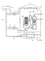
図1は、格納容器内と散布用冷却材再循環設備とを示す構成図である。格納容器110は、内部に一次冷却系を収容する。一次冷却系は、例えば、加圧水型原子炉120と、加圧器130と、蒸気発生器140と、一次冷却材ポンプ150と、一次冷却系流路160とを含んで構成される。
(Embodiment 1)
FIG. 1 is a configuration diagram showing the inside of a containment vessel and a spraying coolant recirculation facility. The
一次冷却系流路160は、加圧水型原子炉120に供給される一次冷却材が循環する通路である。一次冷却系流路160には、加圧水型原子炉120から一次冷却材の流れの方向に向かって順に、加圧器130と、蒸気発生器140と、一次冷却材ポンプ150とが設けられる。
The primary cooling
一次冷却系流路160内の一次冷却材は、加圧器130によって加圧される。一次冷却材ポンプ150が駆動すると、加圧水型原子炉120から一次冷却材が送り出される。加圧水型原子炉120から送り出された一次冷却材は、蒸気発生器140に導かれる。
The primary coolant in the primary
蒸気発生器140は、導かれた一次冷却材と、タービンに供給される二次冷却材との間で熱交換させる。これにより、蒸気発生器140は、導かれた一次冷却材の熱を、蒸気発生器140に二次冷却系から導かれた二次冷却材に伝える。
The
蒸気発生器140により、二次冷却材との間で熱交換した後の一次冷却材は、一次冷却材ポンプ150に導かれ、加圧水型原子炉120に送り出される。このようにして、一次冷却材は、一次冷却系流路160を循環する。
The primary coolant after heat exchange with the secondary coolant by the
ここで、格納容器110及び格納容器110内の設備は、不具合が発生しないように設計、メンテナンスされて、十分な安全が確保されている。図1に示す、散布用冷却材再循環設備10は、仮に不具合が発生した場合を想定した設備であって、加圧水型原子炉120を備えるプラントの安全性をさらに向上させるための設備である。本実施形態では、仮に一次冷却系流路160から一次冷却材が漏れる不具合が発生したものとして説明する。
Here, the
散布用冷却材再循環設備10は、一次冷却材第1流路11と、一次冷却材第2流路12と、一次冷却材第3流路13と、タンク14と、一次冷却材注入用ポンプ15と、一次冷却材散布用ポンプ16と、冷却機17と、スプレイリング18と、ピット19とを含んで構成される。
The spraying
タンク14は、加圧水型原子炉120の燃料を取り替える際や、不具合が発生した際に用いられる冷却材が溜められる。ここで、前記冷却材は、基本的には、一次冷却系流路160の内部を流れる一次冷却材と同一である。
The
本実施形態では、説明の便宜上、一次冷却系流路160内の冷却材を一次冷却材という。また、タンク14内の冷却材や、一次冷却系流路160から漏れ出た一次冷却材がスプレイリング18から散布された冷却材に混ざったものを単に冷却材という。
In the present embodiment, for convenience of explanation, the coolant in the primary cooling
ピット19は、格納容器110の床112に形成される。ピット19は、床112の基面112aよりも鉛直方向下側に窪んで形成される。ピット19には、一次冷却系流路160から漏れ出た冷却材や、スプレイリング18から散布された冷却材が溜まる。
The
一次冷却材第1流路11、一次冷却材第2流路12、一次冷却材第3流路13は、冷却材が流れる通路である。一次冷却材第1流路11は、一方の端部がタンク14に開口し、他方の端部がピット19に開口する。
The primary coolant
一次冷却材第2流路12は、一方の端部が一次冷却材第1流路11に開口し、他方の端部が一次冷却系流路160に開口する。一次冷却材第2流路12を流れる冷却材は、一次冷却材第1流路11から一次冷却系流路160に向かって流れる。
One end of the primary coolant
一次冷却材第3流路13は、一部分が格納容器110の天井111に配置される。一次冷却材第3流路13は、一方の端部が一次冷却材第1流路11に開口し、他方の端部であって天井111に配置される側の端部には、スプレイリング18に冷却材を供給するための開口が形成される。
A portion of the primary coolant
一次冷却材第3流路13のうち、天井111に配置される部分には、複数のスプレイリング18が取り付けられる。これにより、複数のスプレイリング18に一次冷却材第3流路13内を流れる冷却材が供給される。
A plurality of spraying 18 is attached to a portion of the primary coolant
一次冷却材第2流路12には、一次冷却材第1流路11側から一次冷却系流路160に向かって順に、一次冷却材注入用ポンプ15と冷却機17とが設けられる。一次冷却材注入用ポンプ15が稼動すると、一次冷却材第1流路11内の冷却材は、まず一次冷却材第2流路12に吸い込まれる。次に、一次冷却材第2流路12内の冷却材は、冷却機17によって冷却されて、一次冷却系流路160に注入される。
The primary coolant second flow
一次冷却材第3流路13には、一次冷却材第1流路11側から閉塞する側の端部に向かって順に、一次冷却材散布用ポンプ16と冷却機17と複数のスプレイリング18とが設けられる。一次冷却材散布用ポンプ16が稼動すると、一次冷却材第1流路11内の冷却材は、まず一次冷却材第3流路13に吸い込まれる。次に、一次冷却材第3流路13内の冷却材は、冷却機17によって冷却されて、スプレイリング18に供給される。
In the primary coolant
スプレイリング18は、天井111に設けられて、床112に向けて冷却材を散布する。スプレイリング18から散布された冷却材は、格納容器110内に降りかかる。これにより、仮に不具合が発生したときでも、散布用冷却材再循環設備10は前記一次冷却系から漏れ出た高温の冷却材が蒸気となることに起因する格納容器110内の圧力の上昇を抑制できる。
The
なお、一次冷却材第3流路13及びスプレイリング18が配置される場所は、天井111に限定されず、例えば、格納容器110の側壁でもよい。一次冷却材第3流路13及びスプレイリング18は、格納容器110内に冷却材を散布できる位置に配置されればよい。
In addition, the place where the primary coolant
次に、仮に不具合が発生した時の散布用冷却材再循環設備10の動作を説明する。一次冷却系流路160から一次冷却材が漏れ出すと、まず、一次冷却材注入用ポンプ15及び一次冷却材散布用ポンプ16が稼動する。
Next, the operation of the spraying
これにより、タンク14内の冷却材は、一次冷却材第1流路11、一次冷却材第2流路12を流れて、一次冷却系流路160に注入される。また、タンク14内の冷却材は、一次冷却材第1流路11、一次冷却材第3流路13を流れて、スプレイリング18から散布される。
Thereby, the coolant in the
スプレイリング18から散布された冷却材は、格納容器110を冷却した後、床112に落ちてピット19に流れ込む。この時、床112上の冷却材は、図1に示す原子炉格納容器用ストレーナとしてのストレーナ20によって、異物が除去されてピット19に流れ込む。ここで、異物とは、例えば、一次冷却系流路160の配管の表面から飛散した保温材である。
The coolant sprayed from the spraying 18 cools the
ストレーナ20によって異物が除去されてピット19に流れ込んだ冷却材は、ピット19に開口する一次冷却材第1流路11に吸い込まれる。一次冷却材第1流路11に導かれた冷却材は、一次冷却材注入用ポンプ15によって、一次冷却材第2流路12を流れて一次冷却系流路160に供給される。また、ピット19から一次冷却材第1流路11に導かれた冷却材は、一次冷却材散布用ポンプ16によって、一次冷却材第3流路13を流れてスプレイリング18に供給される。
Strainer 2 0 foreign matter is removed by the coolant flowing into the
スプレイリング18に供給された冷却材は、スプレイリング18から格納容器110内に散布される。スプレイリング18によって散布された冷却材は、再度、ストレーナ20を介してピット19に流れ込む。このようにして、不具合が生じた際にスプレイリング18から散布される冷却材は循環する。
The coolant supplied to the
ここで、従来、冷却材に含まれる異物を除去するストレーナは、ピット19の内部に収納されていた。ピット19の内部とは、ピット19の底面と側壁とで囲まれる空間であって、床112の基面112aより前記底面側の空間である。よって、従来のストレーナの大きさは、ピット19の内部に納まる大きさであった。
Here, conventionally, the strainer for removing the foreign matter contained in the coolant has been housed in the
しかしながら、近年、ストレーナに求められる基準であって、冷却材に含まれる異物を除去する部分の面積の基準が、従来の基準よりも高くなった。以下、ストレーナの部分であって、異物を除去する部分の面積をストレーナ面積という。 However, in recent years, the standard required for strainers, which is the standard for the area of a portion for removing foreign substances contained in the coolant, has become higher than the conventional standard. Hereinafter, the area of the portion of the strainer from which foreign matter is removed is referred to as the strainer area.
ストレーナ面積を増加することにより、ストレーナに生じる目詰まりを低減できる。これにより、加圧水型原子炉120を備えるプラントは、安全性が向上する。しかしながら、上述したように、従来、ストレーナはピット19に収納されていた。よって、ストレーナをピット19に収納して配置する場合、例えば、格納容器110は、ピット19を拡大する工事が必要となる。
By increasing the strainer area, clogging occurring in the strainer can be reduced. Thereby, the safety | security of the plant provided with the
しかしながら、既設のプラントでは、ピット19を拡大する工事は、大規模な工事となる。また、既設のプラントでは、現状のピット19の大きさで、設計上の安全が確保されている。よって、現状のピット19に対して、ピット19を拡大する工事のような、設計の変更をともなう大規模な工事を行うことは好ましくない。
However, in the existing plant, the construction for expanding the
これに対して、本実施形態のストレーナ20は、ピット19を拡大することなく、ストレーナ面積を増加できる。これにより、ストレーナ20は、既設のプラントであっても、安全を確保された設計を維持しつつ、ストレーナ面積が増加することで加圧水型原子炉120を備えるプラントの安全性をより向上できる。
In contrast, strainer 2 0 of the present embodiment, without increasing the
図2は、実施形態1に係るストレーナを示す斜視図である。図3は、実施形態1に係るストレーナを鉛直方向に沿う面で切った断面図である。図2及び図3に示すように、ストレーナ20は、ピット19の外部にストレーナモジュール21が配置される点に特徴がある。本実施形態では、ストレーナ20は、例えば、床112の基面112aよりも鉛直方向上側に配置される。
Figure 2 is a perspective view showing a strainer according to the first embodiment. Figure 3 is a sectional view taken along a plane along a strainer according to the first embodiment in the vertical direction. As shown in FIGS. 2 and 3, strainer 2 0 is characterized in that the
図2に示すように、ストレーナ20は、ストレーナモジュール21と、流路形成手段としての流路形成部材22と、基礎23とを含んで構成される。図3に示すように、床112の基面112a上には、基面112aから鉛直方向上側に向かって順に、基礎23、流路形成部材22、ストレーナモジュール21が配置される。基礎23は、例えば、速乾性のコンクリートによって床112に形成される。
As shown in FIG. 2, strainer 2 0 it is configured to include a
流路形成部材22は、基礎23に隙間なく取り付けられて配置される。なお、冷却材に含まれる異物よりも小さい隙間であれば、隙間がないものとして扱う。また、意図しない隙間、例えば、加工の精度によって生じる基礎23と流路形成部材22との間の微小な隙間は、本実施形態では、隙間がないものとして扱う。
The flow
流路形成部材22は、ストレーナモジュール21と基礎23との間で、冷却材が流れる流路であって冷却材をピット19に導くための流路を確保する。また、流路形成部材22は、ピット19を覆うように基礎23に隙間なく取り付けられて、ピット19を塞ぐ。なお、ここでいう「塞ぐ」とは、ストレーナ20の外部の異物を含む冷却材がピット19へ流れ込まないようにすることをいう。
The flow
流路形成部材22は、例えば、内部が空洞の箱型に形成される。流路形成部材22の内部に形成された空洞には、後述するコアチューブ21bが開口するコアチューブ用開口22a、及び、ピット19に連通するピット用開口22bの2つの開口が形成される。
The flow
または、流路形成部材22は、例えば、一方の開口端であるコアチューブ用開口22aがコアチューブ21bに接続され、他方の開口端であるピット用開口22bがピット19に開口する通路を有する。このようにして、流路形成部材22は、冷却材をコアチューブ21bからピット19へと導く。
Alternatively, the flow
ここで、コアチューブ21bから流路形成部材22に流れ込む冷却材は、異物が除去された後の冷却材である。上述したように、流路形成部材22は、基礎23に隙間なく取り付けられるため、異物が除去された後の冷却材は、異物を含む冷却材とは理論上混ざり合わない。
Here, the coolant flowing into the flow
ストレーナモジュール21は、板状に形成されるディスク21aを複数積み重ねられて構成される。ディスク21aは、冷却材に含まれる異物よりも小さい孔を複数有する形状、例えば、網状に形成される。ストレーナモジュール21の部分の中で、冷却材に含まれる異物を除去する部分は、ディスク21aである。よって、ストレーナ面積は、複数のディスク21aの面積の総和になる。
The
図3に示すように、ストレーナモジュール21は、コアチューブ21bを有する。コアチューブ21bには、それぞれのディスク21aが取り付けられる。コアチューブ21bの部分であって、ディスク21aが取り付けられる部分には、コアチューブ21bの内部と外部とを連通する孔が形成される。この孔を介して、ディスク21aによって異物が除去された冷却材は、コアチューブ21bの内部に流れ込む。
As shown in FIG. 3, the
コアチューブ21bは、流路形成部材22のコアチューブ用開口22aに接続される。これにより、異物が除去された冷却材は、コアチューブ21b内をコアチューブ用開口22aに向かって流れ、コアチューブ用開口22aを介して流路形成部材22の内部の流路に流れ込む。
The
前記流路は、コアチューブ用開口22a及びピット用開口22b以外は閉塞されている。よって、ストレーナ20の外部の異物を含む冷却材は、流路形成部材22の内部へは流れ込まない。よって、異物が除去された冷却材は、異物を含む冷却材と混ざることなく、ピット19に導かれる。
The flow path is closed except for the core tube opening 22a and the
なお、本実施形態のストレーナ20は、ストレーナモジュール21の構成ではなく、ストレーナモジュール21の設置方法に特徴がある。よって、ストレーナ20には、従来、周知のストレーナモジュールを用いてもよい。
Incidentally, strainer 2 0 of the present embodiment is not a configuration of the
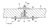
図4は、基礎を床に形成する方法を説明する断面図である。基礎23は、プレート24を介して床112に固定される。具体的には、基礎23は、図4に示すようにプレート24と、アンカーボルト25と、基礎ボルト26とによって床112に固定される。以下に、基礎23の形成方法を説明する。
FIG. 4 is a cross-sectional view illustrating a method for forming a foundation on a floor. The
まず、基礎23が形成される床112の基面112aを削って平面を出す。また、コンクリートの定着を向上するために、基面112aに傷をつける。次に、基面112aにプレート24が設置される。
First, the
プレート24は、板状の部材であって、床112の鉄筋と基礎ボルト26との干渉を避けるための部材である。ここで、基礎23と、流路形成部材22とを床112に固定する基礎ボルト26の設置位置は、変更しないほうが好ましい。例えば、床112に直接基礎ボルト26を打ち込む場合、床112の鉄筋と基礎ボルト26とが干渉するおそれがある。
The
このような場合、基礎ボルト26の設置位置を移動すれば、床112の鉄筋と基礎ボルト26との干渉は避けられる。しかしながら、基礎ボルト26の設置位置を変更すると、現状のストレーナ20の設計が、安全が確保された設計から変更された設計となる場合が想定される。これにより、再度、ストレーナ20は、安全性が確保できているか否かの計算及び試験が必要となる。
In such a case, if the installation position of the
そこで、まず、プレート24を複数のアンカーボルト25で床112に固定する。この時、アンカーボルト25は、床112の鉄筋を避けて床112に打ち込まれる。この時、基礎ボルト26の設置位置は、安全が確保されている設計の位置と一致する。ここで、図4に示すように、プレート24は、基礎ボルト取り付けナット24aを有する。また、プレート24は、例えば、突起部24bを有して形成されてもよい。
Therefore, first, the
基礎ボルト取り付けナット24aは、基礎ボルト26をプレート24に固定するためのナットである。但し、基礎ボルト26は、プレート24と一体に形成されてもよい。この場合、プレート24は、基礎ボルト取り付けナット24aが不要となる。突起部24bは、板状のプレート24から突出する部分であり、基礎23をより良好にプレート24に定着させるための部分である。
The foundation
床112にプレート24がアンカーボルト25で固定され、プレート24に基礎ボルト26が取り付けられると、次に、調節ナット26aが基礎ボルト26に取り付けられる。調節ナット26aは、流路形成部材22を水平に基礎23に設置するためのナットである。調節ナット26aは、基礎ボルト26に嵌め込まれて回転させられることにより、基礎ボルト26上を基礎ボルト26の軸方向に移動する。
When the
次に、基礎23を形成する範囲に型枠が設置され、速乾性のコンクリートが前記型枠に流し込まれる。これにより、床112に基礎23が形成される。次に、基礎23に流路形成部材22が設置され、締め付けナット26bによって、流路形成部材22は基礎23に固定される。ここで、流路形成部材22は、基礎23の面のうち、床112とは反対側の面に取り付けられる。
Next, a formwork is installed in a range where the
具体的には、流路形成部材22の一部に基礎ボルト26が貫通する孔が形成され、前記孔に基礎ボルト26が挿入される。流路形成部材22は、締め付けナット26bによって調節ナット26a及び基礎23と、締め付けナット26bとの間に挟みこまれて基礎23に固定される。
Specifically, a hole through which the
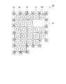
図5は、実施形態1に係る流路形成部材を基礎に設置した状態を格納容器の天井から見た正面図である。図6は、実施形態1に係るプレート及びストレーナモジュールの配置例を格納容器の天井から見た正面図である。上述のように、ストレーナ20は、床112側からプレート24、基礎23、流路形成部材22の順に設置される。既設の格納容器にストレーナ20を設けた場合、プレート24、基礎23、流路形成部材22は、例えば図5のように設置される。
FIG. 5 is a front view of the state in which the flow path forming member according to Embodiment 1 is installed as viewed from the ceiling of the containment vessel. FIG. 6 is a front view of an arrangement example of plates and strainer modules according to the first embodiment as viewed from the ceiling of the storage container. As described above, strainer 2 0, the
格納容器110内には、1つのピット19あたり、例えば、22個のプレート24が設置される。ここで、格納容器110内には、少なくとも1つのピット19が形成される。なお、格納容器110に複数のピット19が形成される場合であっても、それぞれのピット19に設けられるストレーナ20は同様の構成である。よって、以下、1つのピット19あたりに設けられるストレーナ20の構成を説明する。
In the
プレート24は、床112に形成されるピット19を囲うように設置される。基礎23は、複数のプレート24をすべて内包するように、ピット19を除く床112に設置される。流路形成部材22は、22個のプレート24に対して1つずつ設けられる22個の基礎ボルト26をすべて内包するように、基礎23に設置される。
The
ストレーナモジュール21は、このようにして設置された流路形成部材22に、図6に示すように、例えば、24基設置される。ここで、ストレーナモジュール21は、流路形成部材22の面のうち、床112とは反対側の面に取り付けられる。このようにして、ストレーナ20は、ピット19に収納できる数を超えるストレーナモジュール21を備えることができる。
As shown in FIG. 6, for example, 24
これにより、ストレーナ20は、従来よりも、ストレーナ面積が向上する。よって、ストレーナ20は、図2及び図3に示すディスク21aの目詰まりが抑制される。結果として、ストレーナ20は、加圧水型原子炉120を備えるプラントの安全性を向上できる。
Thus, strainer 2 0 than conventional, is improved strainer area. Therefore, strainer 2 0, clogging of the
(実施形態2)
図7は、実施形態2に係る枠型基礎を格納容器の天井から見た正面図である。図7に示すように、実施形態2のストレーナ30は、実施形態1の流路形成部材22に代えてボード32及び枠型基礎33を含んで構成される流路形成手段を備える。ストレーナ30は、ピット19の外部にストレーナモジュール21が配置される点で、ストレーナ20と共通する。
(Embodiment 2)
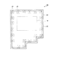
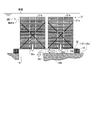
FIG. 7 is a front view of the frame-type foundation according to the second embodiment as seen from the ceiling of the storage container. As shown in FIG. 7, strainer 3 0 embodiment 2 is provided with a configured flow path forming means comprise a
実施形態1の基礎23は、図5に示すように、複数のプレート24を全て含んでピット19を除く床112に形成される。一方、枠型基礎33は、図7に示すように、ボード32に形成される開口であって複数のストレーナモジュール21のコアチューブ21bが接続されるコアチューブ用開口32aよりも外側に枠型に形成される。
As shown in FIG. 5, the
ここで、枠型基礎33に取り付けられたボード32を、格納容器110の天井111から床112に向かって投影すると、枠型基礎33の枠内には、ピット19及び複数のコアチューブ用開口32a全てが内包される。なお、枠型基礎33の床112への設置方法は、実施形態1に記載の方法と同様である。
Here, when the
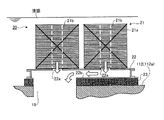
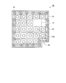
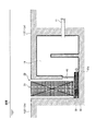
図8は、実施形態2に係るストレーナを示す斜視図である。図9は、実施形態2に係るストレーナを鉛直方向に沿う面で切った断面図である。床112に枠状の枠型基礎33が設置された後、図8に示すように、枠型基礎33には、ボード32が設置される。
Figure 8 is a perspective view showing a strainer according to the second embodiment. Figure 9 is a sectional view taken along a plane along the strainer according to Embodiment 2 in the vertical direction. After the frame-shaped
ボード32は、図3に示す流路形成部材22よりも鉛直方向の厚みが薄く形成される。次に、ボード32のコアチューブ用開口32aにコアチューブ21bが接続される。これにより、ボード32の面のうち、床112と反対側の面に、ストレーナモジュール21が配置される。
The
ボード32は、図9に示すように、リブ、支柱等の補強部材32bによって補強される。これにより、ボード32は、ボード32自身の重さ、及び、ボード32に取り付けられる図9に示すストレーナモジュール21の重さによる撓みが抑制される。
As shown in FIG. 9, the
ここで、図9に示すボード32と、枠型基礎33と、基面112aとによって囲まれる空間が、異物が除去された冷却材が流れる流路となる。枠型基礎33とボード32との間は密閉される。これにより、ストレーナ30の外部の冷却材であって、異物が含まれる冷却材は、ボード32と、枠型基礎33と、基面112aとによって囲まれる空間へは流れ込まない。
Here, the space surrounded by the
ディスク21aによって異物が除去された冷却材は、コアチューブ21bを流れてコアチューブ用開口32aを介してボード32と、枠型基礎33と、基面112aとによって囲まれる空間へ流れ込む。ボード32と、枠型基礎33と、基面112aとによって囲まれる空間へ流れ込んだ冷却材は、ピット19へ導かれる。
The coolant from which foreign matter has been removed by the
上述のように、図9に示すボード32は、図3に示す流路形成部材22よりも、鉛直方向の厚みが薄く形成される。よって、冷却材の液面が同一の場合、ストレーナモジュール21は、ボード32が流路形成部材22よりも鉛直方向に薄く形成される分、ディスク21aが多く設置されることができる。
As described above, the
なお、床112から冷却材の液面までの高さには、下限が設定されている。ストレーナモジュール21は、床112から冷却材の液面までの高さが下限の時でも、全てのディスク21aが前記液面よりも床112側に位置するようにディスク21aが設けられる。
Note that a lower limit is set for the height from the
上記構成により、ストレーナ30は、ストレーナ面積がストレーナ20よりもさらに増加する。よって、ストレーナ30は、ストレーナモジュール21の目詰まりをさらに良好に抑制できる。結果として、ストレーナ30を備えることにより、加圧水型原子炉120を備えるプラントは、安全性がさらに向上する。
With the above structure, strainer 3 0 strainer area is further increased than the strainer 2 0. Therefore, strainer 3 0 can better suppress the clogging of the
また、ストレーナ面積が十分に確保できる場合は、格納容器110内に備えるストレーナモジュール21の基数を低減してもよい。例えば、図7に示すストレーナ30は、図6に示すストレーナ20よりも、備えるストレーナモジュール21の基数が2基少ない。これにより、加圧水型原子炉120を備えるプラントは、格納容器110の内部のスペースのうち、ストレーナ30に要するスペースを減少できる。
Further, when the strainer area can be sufficiently secured, the number of
また、備えるストレーナモジュール21の基数が減少することにより、ストレーナ30は、ボード32の大きさが低減される。支点から力が負荷される部分までの距離が長いほど、撓みは大きくなる。よって、ボード32の大きさが低減されることにより、ストレーナ30は、ボード32の撓みを抑制できる。
Further, since the radix of
(実施形態3)
図10は、ストレーナが床の基面よりも鉛直方向下側に配置される例を示す断面図である。ここで、ピット19は、正確には、一次冷却材第1流路11が開口すると共に流路形成手段の少なくとも一部によって仕切られる空間であって、ストレーナ20の外部の異物を含む冷却材が存在する空間から仕切られる空間である。
(Embodiment 3)
Figure 10 is a sectional view showing an example in which strainer is arranged in the vertically lower than the base surface of the floor. Here, the
よって、図10に示すように、本実施形態では、床112を構成する部材と、流路形成部材22とで囲まれる空間がピット19となる。この場合、基礎23が形成される床112は、基面112aよりも鉛直方向下側に位置する。
Therefore, as shown in FIG. 10, in the present embodiment, the space surrounded by the members constituting the
ここで、基面112aよりも鉛直方向下側に窪んで形成される空間であっても、流路形成手段の少なくとも一部によって仕切られる空間、かつ、一次冷却材第1流路が開口する空間以外は、ピット19には含まれない。例えば、ストレーナ20の外部であって、基面112aよりも鉛直方向下側の空間Aは、ピット19には含まれない。
Here, even in a space that is formed to be recessed downward in the vertical direction from the
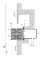
図11は、ストレーナが床の基面よりも鉛直方向下側に配置される他の例を示す断面図である。図11に示すピット19は、一次冷却材第1流路11が開口すると共にストレーナ30の流路形成手段の一部、本実施形態では、枠型基礎33の一部と、隔離部材40とによって仕切られる空間であって、ストレーナ30の外部の異物を含む冷却材が存在する空間から仕切られる空間である。
Figure 11 is a sectional view showing another example of strainer is arranged in the vertically lower than the base surface of the floor. It pits 19 shown in FIG. 11, a portion of the strainer 3 0 of the channel forming unit with the primary coolant
隔離部材40は、床112を構成する部材で形成された壁と、枠型基礎33との間を遮蔽する。ストレーナ30は、ピット19の鉛直方向上側ではなく、図11に示すように、ピット19の側方に配置される。この場合、枠型基礎33は、ピット19に開口するピット用開口33aが形成される。異物が除去された冷却材は、ピット用開口33aからピット19に導かれる。
The
以上、実施形態3のストレーナ20及びストレーナ30は、床112の基面112aよりも鉛直方向下側に配置される。ここで、ストレーナモジュール21が取り付けられる流路形成手段から格納容器110内に溜まった冷却材の液面までの距離は、基面112aから前記液面までの距離よりも大きい。
Above, strainer 2 0 and strainer 3 0 embodiment 3 is disposed vertically lower than the
これにより、ストレーナ20及びストレーナ30は、ストレーナモジュール21が備えるディスク21aの枚数が向上する。これにより、ストレーナ20及びストレーナ30は、従来よりも、ストレーナ面積が向上する。よって、ストレーナ20及びストレーナ30は、図2及び図3に示すディスク21aの目詰まりが抑制される。結果として、ストレーナ20及びストレーナ30は、加圧水型原子炉120を備えるプラントの安全性を向上できる。
Thus, strainer 2 0 and strainer 3 0, improves the number of
以上のように、本発明に係る原子炉格納容器用ストレーナは、冷却材に含まれる異物を除去することに適しており、特に、ストレーナの部分であって、冷却材に含まれる異物を取り除く部分の面積を増加させることに適している。 As described above, the containment vessel for strainer according to the present invention are suitable for removing foreign matter contained in the coolant, in particular, a portion of the strainer to remove foreign matter contained in the coolant Suitable for increasing the area of the part.
10 散布用冷却材再循環設備
11 一次冷却材第1流路
12 一次冷却材第2流路
13 一次冷却材第3流路
14 タンク
15 一次冷却材注入用ポンプ
16 一次冷却材散布用ポンプ
17 冷却機
18 スプレイリング
19 ピット
20 ストレーナ
21 ストレーナモジュール
21a ディスク
21b コアチューブ
22 流路形成部材
22a コアチューブ用開口
22b ピット用開口
23 基礎
24 プレート
24a 基礎ボルト取り付けナット
24b 突起部
25 アンカーボルト
26 基礎ボルト
26a 調節ナット
26b 締め付けナット
30 ストレーナ
32 ボード
32a コアチューブ用開口
32b 補強部材
33 枠型基礎
33a ピット用開口
40 隔離部材
110 格納容器
111 天井
112 床
112a 基面
120 加圧水型原子炉
130 加圧器
140 蒸気発生器
150 一次冷却材ポンプ
160 一次冷却系流路
DESCRIPTION OF
Claims (4)
前記格納容器の床の基面よりも窪んで形成され、前記ストレーナモジュールにより異物が除去された前記冷却材を溜めるピットと、
前記格納容器の床と前記ストレーナモジュールとの間に設けられ、前記ピットを塞ぐと共に、前記ストレーナモジュールにより異物が除去された後の前記冷却材を前記ピットへ導く流路が形成された流路形成手段と、
を備え、前記ピットを塞ぐ前記流路形成手段に前記ストレーナモジュールを配置し、前記流路形成手段は、枠型に形成された基礎であって、前記格納容器の天井から前記格納容器の床に向かって前記基礎を投影した枠内に、前記ストレーナモジュールにより前記異物が除去された前記冷却材を前記ストレーナモジュール内部のコアチューブに流れ込ませ、前記流路形成手段に導入するコアチューブ用開口部と前記ピットとを内包する枠型基礎と、前記枠型基礎の面のうち、前記床と反対側の面に取り付けられ、前記コアチューブ用開口部が形成されるボードと、を含んでいることを特徴とする原子炉格納容器用ストレーナ。 A plurality of disks formed in a plate shape to remove foreign substances contained in the coolant leaked from the primary cooling system of the pressurized water reactor and the coolant sprayed in the containment vessel containing the pressurized water reactor. Strainer module,
A pit that is formed to be recessed from the base surface of the floor of the containment vessel and collects the coolant from which foreign matter has been removed by the strainer module;
A flow path formation provided between the floor of the containment vessel and the strainer module to block the pit and to guide the coolant after the foreign matter has been removed by the strainer module to the pit. Means,
The strainer module is disposed in the flow path forming means that closes the pit, and the flow path forming means is a frame-shaped foundation that extends from the ceiling of the containment vessel to the floor of the containment vessel. A core tube opening for introducing the coolant from which the foreign matter has been removed by the strainer module into the core tube inside the strainer module and introducing it into the flow path forming means in a frame projecting the foundation toward A frame-type foundation including the pit, and a board attached to a surface of the frame-type foundation opposite to the floor and having the core tube opening formed therein. Strainer for reactor containment characterized.
前記異物が除去された前記冷却材が排出される開口が形成される空間であって、前記ボードの少なくとも一部によって仕切られる空間であって、外部の異物を含む前記冷却材が存在する空間から仕切られる空間であることを特徴とする請求項1に記載の原子炉格納容器用ストレーナ。 The pit
A space in which an opening through which the coolant from which the foreign matter has been removed is discharged is formed, is a space partitioned by at least a part of the board , and from a space in which the coolant containing external foreign matter exists The strainer for a nuclear reactor containment vessel according to claim 1, wherein the strainer is a partitioned space.
Priority Applications (1)
| Application Number | Priority Date | Filing Date | Title |
|---|---|---|---|
| JP2008198739A JP4875673B2 (en) | 2008-07-31 | 2008-07-31 | Strainer for reactor containment |
Applications Claiming Priority (1)
| Application Number | Priority Date | Filing Date | Title |
|---|---|---|---|
| JP2008198739A JP4875673B2 (en) | 2008-07-31 | 2008-07-31 | Strainer for reactor containment |
Publications (2)
| Publication Number | Publication Date |
|---|---|
| JP2010038577A JP2010038577A (en) | 2010-02-18 |
| JP4875673B2 true JP4875673B2 (en) | 2012-02-15 |
Family
ID=42011303
Family Applications (1)
| Application Number | Title | Priority Date | Filing Date |
|---|---|---|---|
| JP2008198739A Active JP4875673B2 (en) | 2008-07-31 | 2008-07-31 | Strainer for reactor containment |
Country Status (1)
| Country | Link |
|---|---|
| JP (1) | JP4875673B2 (en) |
Families Citing this family (2)
| Publication number | Priority date | Publication date | Assignee | Title |
|---|---|---|---|---|
| JP2013156195A (en) * | 2012-01-31 | 2013-08-15 | Mitsubishi Heavy Ind Ltd | Water pit structure for nuclear reactor fuel replacement |
| JP6037633B2 (en) * | 2012-03-23 | 2016-12-07 | 三菱重工業株式会社 | Sump screen and sump screen construction method |
Family Cites Families (8)
| Publication number | Priority date | Publication date | Assignee | Title |
|---|---|---|---|---|
| US2378239A (en) * | 1942-12-05 | 1945-06-12 | Leopold Co Inc F B | Filter bottom |
| US3615019A (en) * | 1970-08-13 | 1971-10-26 | Fred J Early Jr | Underdrain system for water filtration plant |
| FR2384324A1 (en) * | 1977-03-16 | 1978-10-13 | Framatome Sa | RECIRCULATION SUMP FOR THE SAFETY INJECTION AND SPRAYING CIRCUITS OF A NUCLEAR REACTOR |
| JPH07260977A (en) * | 1994-03-18 | 1995-10-13 | Mitsubishi Heavy Ind Ltd | Recirculation sump structure in water pit for fuel replacement |
| WO1997036664A1 (en) * | 1996-04-01 | 1997-10-09 | Continuum Dynamics, Inc. | High capacity, low head loss, suction strainer for nuclear reactors |
| DE502004000263D1 (en) * | 2004-01-29 | 2006-04-13 | Cci Ag Winterthur | Protective strainer for shielding a suction chamber |
| US7788867B2 (en) * | 2004-10-13 | 2010-09-07 | General Electric Company | Floor tile debris interceptor and transition plenum in a nuclear power plant |
| US9672947B2 (en) * | 2004-11-15 | 2017-06-06 | Atomic Energy Of Canada Limited | Finned strainer |
-
2008
- 2008-07-31 JP JP2008198739A patent/JP4875673B2/en active Active
Also Published As
| Publication number | Publication date |
|---|---|
| JP2010038577A (en) | 2010-02-18 |
Similar Documents
| Publication | Publication Date | Title |
|---|---|---|
| US20020085660A1 (en) | Boiling water reactor nuclear power plant and its construction method | |
| JP4592773B2 (en) | Static cooling decompression system and pressurized water nuclear plant | |
| CN104919534B (en) | Apparatus and method for removing upper internals from a nuclear reactor pressurized vessel | |
| KR100970913B1 (en) | Modular Integrated Head Assembly | |
| JP6309972B2 (en) | Nuclear power generation facility and method for maintaining liquid level of coolant | |
| EP1755129A2 (en) | Reactor containment vessel cooling equipment and nuclear power plant | |
| KR101129735B1 (en) | Nuclear reactor | |
| KR20110094191A (en) | Integrated ESF Reactor with Improved Convection | |
| JP4620449B2 (en) | Core catcher cooling assembly and nuclear reactor having the assembly | |
| KR20130038867A (en) | Nuclear reactor containment vessel | |
| EP1583105B1 (en) | Pressure suppression and decontamination apparatus and method for reactor container | |
| KR20130000572A (en) | Apparatus for safety improvement of passive type emergency core cooling system with a safeguard vessel and method for heat transfer-function improvement using thereof | |
| JP4875673B2 (en) | Strainer for reactor containment | |
| KR20060052234A (en) | Flooring system for nuclear power plant | |
| JP2009075001A (en) | Nuclear reactor | |
| JP2017062158A (en) | Core melt holding device and reactor containment vessel | |
| WO2025167112A1 (en) | Offshore nuclear power platform and reactor-compartment arrangement structure of offshore nuclear power platform | |
| JP2013108772A (en) | Melt collector | |
| JP4794149B2 (en) | Apparatus for supporting nuclear fuel assemblies in a reactor pressure vessel containing a reactor core | |
| JP4458489B2 (en) | Channel forming device and natural circulation boiling water reactor | |
| JPH07333383A (en) | Nuclear power plant | |
| JP2012008048A (en) | Pressure loss adjustment member and atomic reactor | |
| KR20130083187A (en) | System of flooding for external reactor vessel | |
| JP2021009082A (en) | Fuel assembly and core of light water reactor | |
| KR20240146719A (en) | Cooling System Of Small Modular Reactor |
Legal Events
| Date | Code | Title | Description |
|---|---|---|---|
| A977 | Report on retrieval |
Free format text: JAPANESE INTERMEDIATE CODE: A971007 Effective date: 20100519 |
|
| A131 | Notification of reasons for refusal |
Free format text: JAPANESE INTERMEDIATE CODE: A131 Effective date: 20100525 |
|
| A521 | Written amendment |
Free format text: JAPANESE INTERMEDIATE CODE: A523 Effective date: 20100723 |
|
| A131 | Notification of reasons for refusal |
Free format text: JAPANESE INTERMEDIATE CODE: A131 Effective date: 20110614 |
|
| A521 | Written amendment |
Free format text: JAPANESE INTERMEDIATE CODE: A523 Effective date: 20110810 |
|
| TRDD | Decision of grant or rejection written | ||
| A01 | Written decision to grant a patent or to grant a registration (utility model) |
Free format text: JAPANESE INTERMEDIATE CODE: A01 Effective date: 20111101 |
|
| A01 | Written decision to grant a patent or to grant a registration (utility model) |
Free format text: JAPANESE INTERMEDIATE CODE: A01 |
|
| A61 | First payment of annual fees (during grant procedure) |
Free format text: JAPANESE INTERMEDIATE CODE: A61 Effective date: 20111125 |
|
| FPAY | Renewal fee payment (event date is renewal date of database) |
Free format text: PAYMENT UNTIL: 20141202 Year of fee payment: 3 |
|
| R151 | Written notification of patent or utility model registration |
Ref document number: 4875673 Country of ref document: JP Free format text: JAPANESE INTERMEDIATE CODE: R151 |
|
| FPAY | Renewal fee payment (event date is renewal date of database) |
Free format text: PAYMENT UNTIL: 20141202 Year of fee payment: 3 |