JP4874964B2 - Control method of hitting device, software product, hitting device - Google Patents
Control method of hitting device, software product, hitting device Download PDFInfo
- Publication number
- JP4874964B2 JP4874964B2 JP2007518630A JP2007518630A JP4874964B2 JP 4874964 B2 JP4874964 B2 JP 4874964B2 JP 2007518630 A JP2007518630 A JP 2007518630A JP 2007518630 A JP2007518630 A JP 2007518630A JP 4874964 B2 JP4874964 B2 JP 4874964B2
- Authority
- JP
- Japan
- Prior art keywords
- tool
- wave
- impact
- stress wave
- compressive stress
- Prior art date
- Legal status (The legal status is an assumption and is not a legal conclusion. Google has not performed a legal analysis and makes no representation as to the accuracy of the status listed.)
- Expired - Fee Related
Links
- 238000000034 method Methods 0.000 title claims description 19
- 239000011435 rock Substances 0.000 claims description 48
- 238000005553 drilling Methods 0.000 claims description 37
- 230000035939 shock Effects 0.000 claims description 25
- 230000001902 propagating effect Effects 0.000 claims description 22
- 239000000463 material Substances 0.000 claims description 18
- 230000003116 impacting effect Effects 0.000 claims description 10
- 230000006835 compression Effects 0.000 claims description 9
- 238000007906 compression Methods 0.000 claims description 9
- 238000009527 percussion Methods 0.000 claims 10
- 238000007664 blowing Methods 0.000 claims 1
- 230000003111 delayed effect Effects 0.000 claims 1
- 239000007788 liquid Substances 0.000 description 39
- 230000005540 biological transmission Effects 0.000 description 15
- 230000000644 propagated effect Effects 0.000 description 6
- 230000035515 penetration Effects 0.000 description 5
- 238000005259 measurement Methods 0.000 description 4
- 239000012530 fluid Substances 0.000 description 3
- 230000000694 effects Effects 0.000 description 2
- 230000000750 progressive effect Effects 0.000 description 2
- 239000011343 solid material Substances 0.000 description 2
- 229910000831 Steel Inorganic materials 0.000 description 1
- 230000001133 acceleration Effects 0.000 description 1
- 230000004323 axial length Effects 0.000 description 1
- 238000004891 communication Methods 0.000 description 1
- 238000004590 computer program Methods 0.000 description 1
- 238000011217 control strategy Methods 0.000 description 1
- 238000010586 diagram Methods 0.000 description 1
- 238000009434 installation Methods 0.000 description 1
- 238000012067 mathematical method Methods 0.000 description 1
- 238000005065 mining Methods 0.000 description 1
- 230000003472 neutralizing effect Effects 0.000 description 1
- 239000002994 raw material Substances 0.000 description 1
- 239000010959 steel Substances 0.000 description 1
Images


Classifications
-
- B—PERFORMING OPERATIONS; TRANSPORTING
- B25—HAND TOOLS; PORTABLE POWER-DRIVEN TOOLS; MANIPULATORS
- B25D—PERCUSSIVE TOOLS
- B25D9/00—Portable percussive tools with fluid-pressure drive, i.e. driven directly by fluids, e.g. having several percussive tool bits operated simultaneously
- B25D9/14—Control devices for the reciprocating piston
- B25D9/26—Control devices for adjusting the stroke of the piston or the force or frequency of impact thereof
-
- E—FIXED CONSTRUCTIONS
- E21—EARTH DRILLING; MINING
- E21B—EARTH DRILLING, e.g. DEEP DRILLING; OBTAINING OIL, GAS, WATER, SOLUBLE OR MELTABLE MATERIALS OR A SLURRY OF MINERALS FROM WELLS
- E21B1/00—Percussion drilling
-
- E—FIXED CONSTRUCTIONS
- E21—EARTH DRILLING; MINING
- E21B—EARTH DRILLING, e.g. DEEP DRILLING; OBTAINING OIL, GAS, WATER, SOLUBLE OR MELTABLE MATERIALS OR A SLURRY OF MINERALS FROM WELLS
- E21B44/00—Automatic control systems specially adapted for drilling operations, i.e. self-operating systems which function to carry out or modify a drilling operation without intervention of a human operator, e.g. computer-controlled drilling systems; Systems specially adapted for monitoring a plurality of drilling variables or conditions
- E21B44/02—Automatic control of the tool feed
- E21B44/08—Automatic control of the tool feed in response to the amplitude of the movement of the percussion tool, e.g. jump or recoil
-
- E—FIXED CONSTRUCTIONS
- E21—EARTH DRILLING; MINING
- E21B—EARTH DRILLING, e.g. DEEP DRILLING; OBTAINING OIL, GAS, WATER, SOLUBLE OR MELTABLE MATERIALS OR A SLURRY OF MINERALS FROM WELLS
- E21B6/00—Drives for drilling with combined rotary and percussive action
-
- B—PERFORMING OPERATIONS; TRANSPORTING
- B25—HAND TOOLS; PORTABLE POWER-DRIVEN TOOLS; MANIPULATORS
- B25D—PERCUSSIVE TOOLS
- B25D2250/00—General details of portable percussive tools; Components used in portable percussive tools
- B25D2250/221—Sensors
Landscapes
- Engineering & Computer Science (AREA)
- Geology (AREA)
- Life Sciences & Earth Sciences (AREA)
- Mining & Mineral Resources (AREA)
- Physics & Mathematics (AREA)
- Fluid Mechanics (AREA)
- Environmental & Geological Engineering (AREA)
- General Life Sciences & Earth Sciences (AREA)
- Geochemistry & Mineralogy (AREA)
- Mechanical Engineering (AREA)
- Automation & Control Theory (AREA)
- Earth Drilling (AREA)
- Numerical Control (AREA)
- Percussive Tools And Related Accessories (AREA)
Description
本発明は、打撃装置の制御方法に関するもので、当該方法は、穿孔中に削岩機へ連結可能なツールに対して打撃装置によって衝撃パルスを与え、このツールに対して圧縮応力波を生成して、このツールの材料に応じた伝播速度でこのツールの第1の端部から第2の端部へと伝播させ、同時にこのツールの第2の端部から反射して戻る圧縮応力の少なくとも一部を、このツールの第1の端部へ向かう反射波として伝播させて、削岩機における打撃装置およびその衝撃周波数を制御する。 The present invention relates to a control method for a hitting device, which applies a shock pulse by a hitting device to a tool connectable to a rock drilling machine during drilling, and generates a compressive stress wave for the tool. At least one of the compressive stresses propagating from the first end of the tool to the second end at a propagation velocity depending on the material of the tool and reflected back from the second end of the tool. The part is propagated as a reflected wave toward the first end of the tool to control the impact device and its impact frequency in the rock drill.
さらに、本発明は、打撃削岩を制御するソフトウエア製品に関するもので、削岩を制御する制御装置における当該ソフトウエアの実行が、少なくとも次の動作を行い、すなわち、穿孔中に削岩機における打撃装置を制御して、削岩機へ連結可能なツールに対して衝撃パルスを与えて、圧縮応力波を、このツールにおいて生成して配し、このツールの材料に応じた伝播速度でこのツールの第1の端部から第2の端部へと伝播させ、同時にこのツールの第2の端部から反射して戻る圧縮応力の少なくとも一部を、このツールの第1の端部へ向かう反射波として伝播させ、さらに打撃装置の衝撃周波数を制御する。 Furthermore, the present invention relates to a software product for controlling a hammering rock, and execution of the software in a control device for controlling rock drilling performs at least the following operations, that is, in a rock drilling machine during drilling. The impact device is controlled to apply a shock pulse to a tool that can be connected to a rock drill, and a compressive stress wave is generated and distributed in the tool, and the tool is propagated at a velocity that depends on the material of the tool. Reflection of at least a portion of the compressive stress propagating from the first end of the tool to the second end and reflecting back from the second end of the tool toward the first end of the tool. It is propagated as a wave, and the impact frequency of the impacting device is controlled.
さらに、本発明は、打撃装置に関するもので、これは、衝撃パルスをツールに対して発生させて、衝撃パルスにより生じた圧縮応力波が配されて、ツールの第1の端部から第2の端部へ伝播し、圧縮応力の少なくとも一部が反射波としてツールの第2の端部から反射して戻り、ツールの第1の端部へ向けて伝播する手段と、打撃装置の衝撃周波数を制御する制御装置と、少なくとも打撃装置の衝撃周波数を決める手段とを含む。 Furthermore, the present invention relates to a striking device, which generates an impact pulse on a tool, and a compressive stress wave generated by the impact pulse is arranged, so that the second end from the first end of the tool. Means for propagating to the end, and at least a portion of the compressive stress is reflected back from the second end of the tool as a reflected wave and propagates toward the first end of the tool; A control device for controlling and means for determining at least the impact frequency of the impact device.
さらに、本発明は、打撃装置に関するもので、これは、衝撃パルスをツールに対して発生させて、衝撃パルスにより生じた圧縮応力波が配されて、ツールの第1の端部から第2の端部へ伝播し、圧縮応力の少なくとも一部が反射波としてツールの第2の端部から反射して戻り、ツールの第1の端部へ向けて伝播する手段と、打撃装置の衝撃周波数を制御する手段と、打撃装置の衝撃周波数を決める手段とを含む。 Furthermore, the present invention relates to a striking device, which generates an impact pulse on a tool, and a compressive stress wave generated by the impact pulse is arranged, so that the second end from the first end of the tool. Means for propagating to the end, and at least a portion of the compressive stress is reflected back from the second end of the tool as a reflected wave and propagates toward the first end of the tool; Means for controlling and means for determining the impact frequency of the striking device.
打撃式削岩は、少なくとも打撃装置とツールとを有する削岩機を用いる。この打撃装置は圧縮応力波を生成し、これがシャンクを介してツールへ、さらにこのツールの最外端部のドリルビットへ伝播する。この圧縮応力波は、ツール内で、ツールの材料に応じた速度で伝播する。したがって、伝播波の、鋼鉄製のツールの場合の速度は、たとえば5,190 m/sになる。圧縮応力波がドリルビットに到達すると、ドリルビットを岩石に貫通させる。しかし、打撃装置により発生するこの圧縮応力波のエネルギーの20ないし50 %が、ツール内で逆方向に、すなわち打撃装置の方へ伝播する反射波としてドリルビットから反射して戻ることが検知されている。穿孔状態にもよるが、この反射波は圧縮応力波もしくは引張応力波しか有することができない。しかし、反射波は、一般には引張応力成分および圧縮応力成分の両方を有している。今日では、この反射波におけるエネルギーを穿孔において十分に利用することができず、これが当然に穿孔の効率を下げている。他方、反射波が、たとえば穿孔機器の耐久性に関する問題を生じていることが知られている。 The hitting rock drill uses a rock drill having at least a hitting device and a tool. The striking device generates a compressive stress wave that propagates through the shank to the tool and further to the drill bit at the outermost end of the tool. This compressive stress wave propagates in the tool at a velocity depending on the material of the tool. Therefore, the velocity of the propagation wave in the case of a steel tool is, for example, 5,190 m / s. When the compressive stress wave reaches the drill bit, it penetrates the rock. However, it has been detected that 20-50% of the energy of this compressive stress wave generated by the striking device is reflected back from the drill bit as a reflected wave propagating in the opposite direction in the tool, ie towards the striking device. Yes. Depending on the perforated state, this reflected wave can only have a compressive stress wave or a tensile stress wave. However, the reflected wave generally has both a tensile stress component and a compressive stress component. Today, the energy in this reflected wave cannot be fully utilized in drilling, which naturally reduces the efficiency of drilling. On the other hand, it is known that reflected waves cause problems with the durability of drilling equipment, for example.
本発明は、新規の改善された方法と、削岩機の打撃装置を制御するソフトウエア製品と、打撃装置を提供することを目的とする。 It is an object of the present invention to provide a new and improved method, a software product for controlling a rock drill hitting device, and a hitting device.
本発明の方法は、用いられるツールの長さに応じた応力波の伝播時間と、このツールの材料における波の伝播速度とに比例する打撃装置の衝撃周波数を設定し、先の圧縮応力波のうちの1つからの反射波がツールの第1の端部へ到達するときに、打撃装置によって新規の圧縮応力波をツールに対して生成し、この新規の圧縮応力波およびこの反射波を合計して合計波を生成し、これをこのツールにおいてこの合計波の伝播速度でこのツールの第2の端部へ向けて伝播させることを特徴とする。 The method of the present invention sets the impact frequency of the striking device proportional to the propagation time of the stress wave according to the length of the tool used and the propagation speed of the wave in the material of the tool. When the reflected wave from one of them reaches the first end of the tool, the impact device generates a new compressive stress wave for the tool and sums this new compressive stress wave and this reflected wave. To generate a total wave, which is propagated in the tool at the propagation speed of the total wave toward the second end of the tool.
本発明のソフトウエア製品は、当該ソフトウエア製品の実行が、応力波の伝播時間に比例する打撃装置の衝撃周波数を設定するよう配設されることを特徴とする。 The software product of the present invention is characterized in that the execution of the software product is arranged to set the impact frequency of the impact device proportional to the propagation time of the stress wave.
本発明の打撃装置は、制御装置が、用いられるツールの長さに応じた応力波の伝播時間と、このツールの材料における波の伝播速度とに比例する衝撃周波数を設定するよう配設されることを特徴とする。 The striking device of the present invention is arranged so that the control device sets an impact frequency proportional to the propagation time of the stress wave according to the length of the tool used and the propagation velocity of the wave in the material of the tool. It is characterized by that.
本発明の第2の打撃装置は、この打撃装置が、衝撃周波数および衝撃エネルギーを無段階および別個に制御する手段を有することと、この打撃装置の衝撃周波数が、用いられるツールの長さとツールの材料における波の伝播速度とに応じた応力波の伝播時間に比例して配されることを特徴とする。 The second striking device of the present invention is characterized in that the striking device has means for controlling the impact frequency and impact energy steplessly and separately, and that the impact frequency of the striking device depends on the length of the tool used and the tool length. It is characterized by being arranged in proportion to the propagation time of the stress wave according to the wave propagation speed in the material.
本発明の本質的な概念は、打撃装置の衝撃周波数が、新しい圧縮応力波がツールに生成されるごとに、先の圧縮応力波からの反射波がツールの打撃装置端部に存在するように配されることにある。衝撃周波数を調節して、応力波の伝播時間に比例させる必要がある。用いられるツールの長さおよびツールの材料における応力波の伝播速度が、応力波の伝播時間に影響を及ぼす。 The essential concept of the present invention is that the impact frequency of the impact device is such that every time a new compressive stress wave is generated in the tool, a reflected wave from the previous compressive stress wave is present at the impact device end of the tool. It is to be arranged. It is necessary to adjust the impact frequency to be proportional to the propagation time of the stress wave. The length of the tool used and the propagation speed of the stress wave in the tool material influence the propagation time of the stress wave.
本発明は、反射波におけるエネルギーがいまや穿孔においてより良く利用できるという利点を提供する。反射波がツールの打撃装置端部へ到達すると、この反射波における引張応力波が反射されて圧縮応力波としてドリルビットの方へ戻される。打撃装置によって生成された新規の一次圧縮応力波がこの反射された圧縮応力波へ合算され、これによって、この反射圧縮応力波と一次圧縮応力波から成る合計波は、打撃装置のみによって生成された圧縮応力波よりも大きなエネルギー含有量を有することになる。また、本発明の方式は、ドリルビットと岩石との間に常に良好な接触を保証する。これは、圧縮応力波だけがツールのドリルビットへ向けて伝播するからである。ツールの第1の端部において、打撃装置により生成される新規の圧縮応力波が反射応力波へ合計された場合、その合計波は常に1つの圧縮応力波となる。したがって、ドリルビットと岩石との間の接触を弱めることがある引張応力波は、ツールのドリルビットへ伝播することがない。さらに、本発明の方式を適用した場合、送り分力が以前よりも弱くなることがある。なぜならば、ドリルビットと岩石との間の良好な接触が、大きな送り分力による引張応力波の影響を補償する必要なく維持されるからである。 The present invention offers the advantage that the energy in the reflected wave can now be better utilized in drilling. When the reflected wave reaches the impacting device end of the tool, the tensile stress wave in the reflected wave is reflected and returned to the drill bit as a compressive stress wave. The new primary compressive stress wave generated by the striking device is added to this reflected compressive stress wave, so that a total wave consisting of this reflected compressive stress wave and the primary compressive stress wave is generated only by the striking device. It will have a greater energy content than the compressive stress wave. Also, the system of the present invention ensures always good contact between the drill bit and the rock. This is because only the compressive stress waves propagate towards the tool drill bit. When the new compressive stress wave generated by the impacting device is summed into the reflected stress wave at the first end of the tool, the total wave is always one compressive stress wave. Thus, tensile stress waves that can weaken the contact between the drill bit and the rock will not propagate to the drill bit of the tool. Furthermore, when the system of the present invention is applied, the feed force may be weaker than before. This is because good contact between the drill bit and the rock is maintained without having to compensate for the effects of tensile stress waves due to high feed force.
本発明の実施例の本質的な概念は、ツールにおいて打撃装置からドリルビットへ向かって伝播する合計波の形が、衝撃周波数を微調整することによって所望のように作られることにある。この微調整は、ツールの第1の端部から反射される圧縮応力波と、打撃装置によって生成される一次圧縮応力波との合算に影響を及ぼし、したがって、この合計波の形に対しても影響を及ぼす。衝撃周波数を穿孔機の長さに基づいて決めた設定よりも大きく設定することによって、1つの累進合計波が得られる。衝撃周波数を低く設定することによって、順次に合計波を長くすることができ、これが実際には圧縮応力の有効時間を長くする。また、衝撃周波数を十分に大きくすることによって合計波を長くすることも当然でき、これによって、反射波は生成された一次圧縮応力波の後方に付される。 The essential idea of an embodiment of the present invention is that the shape of the total wave propagating from the striker to the drill bit in the tool is created as desired by fine tuning the impact frequency. This fine adjustment affects the sum of the compressive stress wave reflected from the first end of the tool and the primary compressive stress wave generated by the striking device, and therefore also for this total wave shape. affect. By setting the impact frequency higher than the setting determined based on the length of the drilling machine, one progressive sum wave is obtained. By setting the impact frequency low, the total wave can be lengthened sequentially, which actually increases the effective time of compressive stress. In addition, it is naturally possible to lengthen the total wave by sufficiently increasing the shock frequency, whereby the reflected wave is added behind the generated primary compressive stress wave.
本発明の実施例の本質的な概念は、伸長ロッド穿孔において、打撃装置の衝撃周波数が1つの伸縮ロッドにおける応力波の伝播時間に相当するように設定されることにある。このとき、ツールの一方の端部から打撃装置へ向かって伝播する反射波は、反対の方向から伝播する一次圧縮応力波と実質的に同時に伸長ロッド間の連結接合部へ伝播する。圧縮応力波および反射波は、この連結接合部へ実質的に同時に到達すると、合計され、これによって反射波の引張応力成分が中和され、したがって、引張応力波はこの連結部へは向かわない。このように、伸長ロッド間の連結部の耐久性を改善することができる。 The essential concept of the embodiment of the present invention is that in the extension rod drilling, the impact frequency of the hitting device is set so as to correspond to the propagation time of the stress wave in one telescopic rod. At this time, the reflected wave propagating from the one end of the tool toward the impacting device propagates to the connecting joint between the extension rods substantially simultaneously with the primary compressive stress wave propagating from the opposite direction. The compressive stress wave and the reflected wave are summed when they reach the joint joint substantially simultaneously, thereby neutralizing the tensile stress component of the reflected wave, so that the tensile stress wave does not go to the joint. Thus, the durability of the connecting portion between the extension rods can be improved.
本発明の実施例の本質的な概念は、新規の一次圧縮応力波が、先の圧縮応力波によって生成された反射波、すなわちツールの一方の端部から他方へ複数回伝播している反射波の多数と合計されることにある。本実施例は短いツールが用いられている場合に特に利用することができる。 The essential concept of an embodiment of the present invention is that the new primary compressive stress wave is a reflected wave generated by the previous compressive stress wave, i.e. a reflected wave propagating multiple times from one end of the tool to the other. Is to be summed up with many of them. This embodiment can be used particularly when a short tool is used.
本発明の実施例の本質的な概念は、打撃装置が圧縮応力成分におけるエネルギーを反射波内に蓄積し、またこれを新規の衝撃パルスの生成に利用する手段を有していることにある。往復打撃ピストンを有する打撃装置において、反射圧縮応力成分におけるエネルギーは、打撃ピストンが戻り方向に移動する場合に利用することができる。この反射圧縮応力成分は、打撃ピストンの戻り運動の初速を生み出すことができる。戻り運動の終わりにおいて、打撃ピストンの運動エネルギーは、蓄圧機に蓄積され、これを新規の打撃運動中に利用することができる。また、打撃装置が公知であるものには、圧縮応力波が打撃ピストンなしで油圧エネルギーから直接的に生成されるものもある。この種の打撃装置において、衝撃周波数を本発明において説明しているように設定した場合、衝撃パルスを小さい入力エネルギーで生成することができる。 The essential concept of an embodiment of the present invention is that the striking device has means for accumulating energy in the compressive stress component in the reflected wave and utilizing it for generating a new shock pulse. In a striking device having a reciprocating striking piston, the energy in the reflected compressive stress component can be utilized when the striking piston moves in the return direction. This reflected compressive stress component can create the initial speed of the return movement of the striking piston. At the end of the return movement, the kinetic energy of the striking piston is stored in the accumulator and can be utilized during a new striking movement. In other known striking devices, a compressive stress wave is generated directly from hydraulic energy without a striking piston. In this type of impact device, when the impact frequency is set as described in the present invention, the impact pulse can be generated with a small input energy.
本発明の実施例の本質的な概念は、打撃装置が衝撃周波数および衝撃エネルギーを無段階、かつ別個に調節することができることにある。たとえば、圧縮応力波を打撃ピストンなしで油圧エネルギーから直接的に生成する打撃装置において、衝撃周波数を、制御弁の回転速度または作動周波数を調節することによって調節することができる。この種の打撃装置において、衝撃エネルギーは、油圧の大きさを調節することによって調節することができる。電動式打撃装置において、衝撃周波数は、たとえば交流の周波数を調節することによって調節することができ、また衝撃エネルギーを、用いられる電圧を変えることによって調節することができる。 The essential concept of an embodiment of the present invention is that the striking device can adjust the impact frequency and impact energy steplessly and separately. For example, in a striking device that generates compressive stress waves directly from hydraulic energy without a striking piston, the impact frequency can be adjusted by adjusting the rotational speed or operating frequency of the control valve. In this type of striking device, the impact energy can be adjusted by adjusting the hydraulic pressure. In an electric impact device, the impact frequency can be adjusted, for example, by adjusting the frequency of the alternating current, and the impact energy can be adjusted by changing the voltage used.
本発明の実施例の本質的な概念は、これが少なくとも100 Hzの衝撃周波数を用いていることにある。 The essential concept of the embodiment of the invention is that it uses an impact frequency of at least 100 Hz.
本発明の実施例の本質的な概念は、これが少なくとも200 Hzの衝撃周波数を用いていることにある。実際の場合、200 Hz以上の衝撃周波数が有利であることが証明されている。 The essential concept of the embodiment of the invention is that it uses an impact frequency of at least 200 Hz. In practice, an impact frequency of 200 Hz or higher has proven advantageous.
次に、添付の図面において、本発明をより詳細に説明する。 The present invention will now be described in more detail with reference to the accompanying drawings.
図面では、明確にするために本発明を簡略化して示す。同様の部分は、図面においては同様の参照番号で示す。 In the drawings, the invention is simplified for clarity. Like parts are indicated by like reference numerals in the drawings.
図1に示す削岩掘削機1は、キャリア2および少なくとも1つの送りビーム3を含み、その上には可動式削岩機4が配設されている。送り装置5により、削岩機4を穿孔される岩石に向けて押し出し、同様にそれから引き離すことができる。送り装置5は、たとえば、1つ以上の油圧式シリンダを有するものでよく、これを適切な動力伝動部材によって削岩機4を移動させるように配設することができる。送りビーム3は、典型的には、キャリア2に関して移動させることができるブーム6へ配設される。削岩機4は、削岩機4へ連結されたツール8に対して衝撃パルスを与える打撃装置7を含む。ツール8は、1つ以上のドリルロッドおよびドリルビット10を含むことができる。さらに、削岩機4は、ツール8をその長手方向の軸を中心に回転させる回転装置11を含むことができる。穿孔中において、衝撃パルスは、打撃装置7によって、回転装置11により同時に回転させることができるツール8に対して与えられる。また、削岩機4は、穿孔中に岩石に対して押し付けられて、ドリルビット10がその岩石を破砕することができる。削岩を1つ以上の制御装置12によって制御することができる。この制御装置12は、コンピュータまたは同様のものを含むことができる。制御装置12は、制御命令を、削岩機4の作動を制御するアクチュエータおよび圧力媒体を制御する弁などの送り装置5に対して与えることができる。削岩機4の打撃装置7、回転装置11および送り装置5は、圧力媒体作動式に、もしくは電動アクチュエータにすることができる。
A
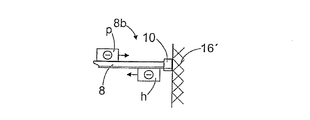
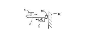
図2aは、ドリルシャンク13へ連結したツール8を伴う削岩機4を示す。この削岩機4の打撃装置7は、前後に移動可能に配設された打撃ピストンなどの打撃部材14を含むことができ、これは、ドリルシャンク13上の打撃面15を打撃し、衝撃パルスを発生させるように配設され、このパルスは、材料に応じた速度で圧縮応力波としてドリルシャンク13およびツール8を介してドリルビット10へ伝播する。図2cには削岩の特殊な事例の一つを示し、圧縮応力波pは、ドリルビット10を岩石16へ貫通させることができない。これは、たとえば、非常に硬い岩の原料16'であるかもしれない。このような場合、最初の応力波pは、圧縮応力波hとしてドリルビット10から反射して戻り打撃装置7に向かう。図2dには第2の特殊な事例を示す。これにおいては、ドリルビット10を抵抗力なしで自由に前進させることができる。たとえば、岩石の空洞の中へ穿孔する場合、穿通抵抗は最小になる。このとき、最初の圧縮応力波pは、ドリルビット10から引張反射波として反射して戻り打撃装置7へ向かう。実際の穿孔では、図2aに示すように、ドリルビット10は抵抗にあうが、圧縮応力波pによりまだ前進することができる。ドリルビット10の前進に対して力が抵抗するが、その力の大きさはドリルビット10が岩石16を穿通する距離による。すなわち、ドリルビット10の穿通が進むほど、抵抗力は大きく、またその逆も然りである。したがって、実際において、引張および圧縮反射成分の両方を含む反射波hは、ドリルビット10から反射される。図において、引張応力は(+)で示し、圧縮応力は(−)で示す。引張反射成分(+)は、反射波hにおいては常に最初のもので、圧縮応力成分(−)は2番目のものである。これは、一次圧縮応力波pの作用の初期段階においてのドリルビット10の穿通および穿通抵抗が小さく、これによって引張反射成分(+)が生成されることによる。したがって、この初期状態は、ドリルビット10を大きな抵抗力なしで前進させることができる上述の特殊な状況に似ている。しかし、一次圧縮応力波pの作用の最終段階においては、ドリルビット10は既に岩石16へ深く穿通しており、この場合、穿通抵抗は大きく、最初の圧縮応力波pは、もはや実質的にはドリルビット10を前方に進めて岩石16に対してより深く押し入れることができない。この状態は、ドリルビット10の岩石16内への進行が妨げられる上述の第2の特殊な事例に似ている。したがって、これによって、ドリルビット10から最初に反射された引張応力波(+)の直後に続く反射圧縮応力波(−)を生成する。
FIG. 2 a shows a rock drill 4 with a
したがって、打撃装置7により生成されてツール8に対して伝播する応力波は、ツールの第1の端部8a、すなわち打撃装置端部から、ツールの第2の端部8b、すなわちドリルビット端部へ伝播し、再びツールの第1の端部8aへ戻る。このとき、この応力波は、ツール8の長さの2倍の距離を伝播する。本発明の概念によれば、打撃装置7の衝撃周波数は、先の応力波の反射波のうちの1つがツール8の第1の端部8aへ到達した実質的にその瞬間に、この打撃装置7が衝撃パルスを生成するように配される。
Thus, the stress wave generated by the
応力波の前後走行距離を決める場合、ドリルビット10の長さを無視することができる。なぜならば、ドリルビット10の軸長は、ツール8の全長に対して非常に短いからである。ドリルシャンク13は、典型的には長いので、長さを考慮に入れることができる。
When determining the travel distance of the stress wave, the length of the
次に、本発明を数式(1)、(2)および(3)を用いて説明する。 Next, the present invention will be described using equations (1), (2) and (3).
ツールの第1の端部から第2の端部への応力波の伝播時間および戻りは、次の数式で計算することができる。

この数式において、LShankはドリルシャンクの長さであり、LRodは1つのドリルロッドの長さである。nがドリルロッドの数である場合、ツールの全長はLtotである。cはツールにおける応力波の伝播速度である。したがって、応力波の伝播時間tkは、ツールの全長Ltotと、ツールの材料における応力波の伝播速度cとによる。 In this formula, L Shank is the length of the drill shank and L Rod is the length of one drill rod. If n is the number of drill rods, the total length of the tool is L tot . c is the propagation speed of the stress wave in the tool. Therefore, the propagation time t k of the stress wave depends on the total length L tot of the tool and the propagation speed c of the stress wave in the tool material.
さらに、周波数を応力波の伝播時間tkに基づいて次の数式により計算することができる。
周波数fkはドリルロッドの軸方向の自然周波数ではなく、この周波数fkはツールの全長と、応力波の伝播速度だけによることに注意する。 Frequency f k is not in the axial direction of the natural frequency of the drill rod, the frequency f k is to note that night and the entire length of the tool, only the propagation velocity of the stress wave.
本発明の概念によれば、打撃装置の衝撃周波数fDは応力波の伝播時間に比例して設定することができる。このとき、衝撃周波数は、次の数式に準拠する。
数式(3)において、mは2つの整数の商または倍数である周波数係数である。 In Equation (3), m is a frequency coefficient that is a quotient or multiple of two integers.
周波数係数mが2つの整数の商である場合、その分子はまた1以外のものでよいことにも注意すべきである。その分母の値は、応力波が、これに対して新規の一次圧縮応力波が合算されるまでに、ツールにおいて何回前後に伝播したかを示すものである。実際において、分母の最大値は4である。 It should also be noted that if the frequency coefficient m is a quotient of two integers, the numerator can also be other than one. The denominator value indicates how many times the stress wave has propagated around the tool before the new primary compressive stress wave is added to it. In practice, the maximum value of the denominator is 4.
したがって、実際には、数式(3)は、穿孔において、衝撃周波数はツールにおける応力波の伝播時間に比例するものが用いられることを意味している。このように、新規の圧縮応力波をツールに対して生成して、これを反射波の引張応力成分と合算することができる。図2bに示すように、反射応力波hがツールの第1の端部8aに到達した場合、引張応力成分(+)は打撃装置へは伝達されない。なぜならば、ツールの第1の端部8aは自由になっているからである。したがって、引張応力成分(+)はツールの第1の端部8aから圧縮応力成分(−)として反射して戻りドリルビット10へ向かう。打撃装置によって、新しい圧縮応力波pが、ツールの第1の端部8aから反射された圧縮応力成分ptotへ合算される。圧縮応力である生成された合計波ptotは、単なる圧縮応力波pよりも大きなエネルギー含有量を有している。さらに、反射圧縮応力成分のエネルギー含有量は小さく、これ自体だけでは岩石を破砕することができない。全体的に、打撃装置7によって生成される衝撃パルスの正確なタイミングが、反射引張応力成分(+)に関して問題である。
Therefore, in actuality, Equation (3) means that in drilling, the impact frequency is proportional to the propagation time of the stress wave in the tool. In this way, a new compressive stress wave can be generated for the tool and summed with the tensile stress component of the reflected wave. As shown in FIG. 2b, when the reflected stress wave h reaches the
図2eは、合計波ptotの形状のいくつかの実施例を示す。引張反射成分の到達に関して新規の圧縮応力波の発生を進行もしくは遅延させることによって、合計波ptotの形状に対して影響を及ぼすことができる。実際において、合計波ptotの形状は、衝撃周波数の微調整によって影響される。衝撃周波数が穿孔装置に基づいて決められた設定よりも高く設定されている場合、図2eの一番左側の合計波ptot1が得られ、これは形状が進行している。衝撃周波数が決められた設置よりも小さく設定されている場合、図2eの右側に示す長い方の合計波ptot2が得られる。後者の場合、打撃装置によって発生される圧縮応力波は、反射圧縮応力成分の後方に付される。また、図2bも、設定に応じた合計波ptotの形状を示す。 FIG. 2e shows several examples of the shape of the total wave p tot . The shape of the total wave p tot can be affected by advancing or delaying the generation of a new compressive stress wave with respect to reaching the tensile reflection component. In practice, the shape of the total wave p tot is affected by fine adjustment of the shock frequency. If the impact frequency is set higher than the setting determined on the basis of the drilling device, the leftmost total wave p tot1 in FIG. 2e is obtained, which is progressive in shape. If the shock frequency is set lower than the determined installation, the longer total wave p tot2 shown on the right side of FIG. 2e is obtained. In the latter case, the compressive stress wave generated by the striking device is applied behind the reflected compressive stress component. FIG. 2b also shows the shape of the total wave p tot according to the settings.
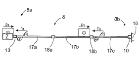
図3ないし図6は、伸長ロッド穿孔の原理を示す。このような場合、ツール8は2つ以上の伸長ロッド17aないし17cを含み、これらは継手18a、18bによって共に連結されている。この継手18は、通常、伸長ロッド17が連結される連結ねじを有している。この継手18は、伸長ロッド17の一部にすることができる。連結された伸長ロッド17は、一般的には実質的に同じ長さである。伸長ロッド穿孔による1つの問題は、ツール8の第2の端部8bから反射された引張応力成分(+)が、継手18およびとくにそれに通される連結ねじを損傷するかもしれないことである。本発明によって、打撃装置7の衝撃周波数を設定して、一次圧縮応力波pが反射引張応力成分(+)と実質的に同時に常に継手18のところにあるようにすることができる。このとき、一次圧縮応力波pおよび反射引張応力成分(+)の効果は、継手18において総計されて、引張応力がこの継手18へ向かうことがないことが確実になる。したがって、継手18および伸長ロッド17の耐久性を以前よりも改善することができる。一次圧縮応力波pをどちらかといえば長くすることができるので、圧縮応力波pおよび反射波hを全く同時に継手18のところにあるようにする必要はなく、反射波hの引張応力成分(+)がそこに到達した場合、圧縮応力波pがこの連結点に対してなお影響を及ぼすには十分である。
3 to 6 show the principle of elongated rod drilling. In such a case, the
伸長ロッド穿孔において、打撃装置7の衝撃周波数を次の数式を用いて応力波の伝播時間に比例して設定することができる。
したがって、衝撃周波数は、1つの伸長ロッド17の長さLRodに応じて設定される。さらに、ドリルシャンク13の長さを無視することができる。なぜならば、ドリルシャンク13の長さは、伸長ロッド17の長さに関して短いからである。
Therefore, the impact frequency is set according to the length L Rod of one
次に、図3ないし図6を参照して、伸長ロッド穿孔における応力波の伝播を詳細に説明する。図3では、穿孔がちょうど開始されて、打撃装置7により生成された第1の圧縮応力波p1が、すでに第3の伸長ロッド17cへ到達している。第2の応力波p2、第3の応力波p3およびその後の応力波が、数式(4)に従って生成され、すなわち、打撃装置7の衝撃周波数が応力波の伝播時間に比例して配される。このとき、ツール8の第2の端部8bから反射された第1の反射波h1は、第2の圧縮応力波p2と実質的に同時に第2の継ぎ手18bへ伝播する。これは図4に示す。さらに、図5の状態において、第1の反射波h1は、反対方向から伝播する第3の圧縮応力波p3がそうであるように、すでに第1の継手18aに到達している。図6において、第2の反射波h2は、第3の圧縮応力波p3と実質的に同時に第2の継手18bへ伝播している。引張応力成分(+)を含む反射波hが連結部へ伝播するごとに、反対方向から伝播する圧縮応力波pもまた連結点へ影響を及ぼし、その結果、圧縮応力波pは引張応力成分(+)を相殺する。
Next, with reference to FIG. 3 to FIG. 6, the propagation of stress waves in the elongated rod drilling will be described in detail. In FIG. 3, the drilling has just started and the first compressive stress wave p1 generated by the
図7ないし図9は、制御弁19のその軸を中心とした回転または転回を調節することによって衝撃周波数に対して影響を及ぼすことができるいくつかの打撃装置7を示す。図7ないし図9の打撃装置によって、非常に高い衝撃周波数を達成することができる。この衝撃周波数を450 Hz以上、1 kHz以上にもすることができる。
FIGS. 7 to 9 show several
図7の打撃装置7は、その中に応力部材21を備えたフレーム20を有している。さらに、この打撃装置は、制御弁19を有し、これは適切な回転メカニズムによってその軸を中心として回転され、またはその軸に関して前後に転回される。この制御弁19は、供給路24および同様の排出路25への連絡部を開閉する交互の開口部22および23を備えることができる。さらに、打撃装置のフレーム20は、第1の加圧液空間26を有することができる。また、打撃装置は、伝動ピストン27などの伝動部材を有することもできる。この打撃装置7の基本原理は、応力部材21の緊張と解放が制御弁19を用いて制御されて、衝撃パルスが生成されることである。この応力部材21を緊張させるため、加圧液供給路24をポンプ28からこの制御弁19における開口部22へと導くことができる。制御弁19が回転すると、これらの開口部22が一度に加圧液の供給路24に到達し、加圧液が加圧液空間26へ流れ込むことができる。この結果、伝動ピストン27が応力部材21に対して押し付けることができ、これによって応力部材21が圧縮する。この圧縮の結果、エネルギーが伝動ピストン27に蓄積され、伝動ピストン27をツール8に向けて押し出そうと努める。制御弁19が矢印Aで示す方向に転回すると、加圧液空間26から開口部23を介して排出路25への連絡部が開かれ、これによって、加圧液空間26内の加圧液が加圧タンク29内へ急速に流入することができる。加圧液が加圧液空間26から出ると、応力部材21は解放され、その応力により生成された力がツール8を圧縮する。応力部材21内に蓄積されたエネルギーは応力パルスとしてツール8内へ伝送する。応力部材21および伝動ピストン27は、それぞれ独立した部品でよく、この場合、応力部材21を固形体の材料で作ることができ、またはこれを第2の加圧液空間30中の加圧液によって作ることができる。応力部材21が固形体の材料で作られる場合、これは伝動ピストン27へ一体化することができる。
The
図8は、図7の打撃装置7の一実施例を示し、この場合、加圧液は制御弁19の制御なしで、ポンプ28から供給路24に沿って第1の加圧液空間26へ直接供給される。このような場合、制御弁19は、加圧液空間26から排出路25へ加圧液を流すことが可能な開口部23を持てば十分である。したがって、この方式は、第1の加圧液空間26からの加圧液の圧力解放を適切な周波数で制御するだけで、ツール8に対して応力パルスを発生する。
FIG. 8 shows an embodiment of the
図9は、打撃装置を示して、第2の加圧液空間30を有し、これが流路31を介して加圧源32へ連絡して、加圧液を加圧液空間30へ供給することができる。この方式において、第2の加圧液空間30内の加圧液を応力部材21として働かせることができる。伝動ピストン27もしくは同様なものによって、第1の加圧液空間26および第2の加圧液空間30を互いから分離することができる。ポンプ28は、加圧液を制御弁19を介して第1の加圧液空間26へ供給することができる。制御弁19を、第1の加圧液空間26から供給路24へ、他方では排出路25への連絡部を開閉するように配設することができる。また、ポンプ28および32を互いに連結することもできる。加圧液が、制御弁19により制御されて、第1の加圧液空間26へ供給されると、伝動ピストン27が矢印Bで示す方向の最後部位置へ移動し、これによって、加圧液は第2の加圧液空間30から出る。この後、制御弁19は、その軸に関して、加圧液が第1の加圧液空間26から排出路25へ急速に流れることのできる位置に転回する。このとき、第2の加圧液空間30内で作動する圧力と、ポンプ32により生成された圧力とが、伝動ピストン27に対して働いて力を生成し、その結果、伝動ピストン27がツール8に向けて押し出る。伝動ピストン27はツール8を圧縮し、その結果、衝撃パルスがツール8に対して発生されて、圧縮応力波pとしてツール8を介して伝播する。穿孔されている岩石からの反射パルスhは、ツール8から打撃装置7へ戻り伝播する。この反射パルスは伝送ピストン27を矢印Bの方向に押し出そうと努め、これによって、この反射パルスのエネルギーが第2の加圧液空間30内の加圧液へ伝動される。このとき、第2の加圧液空間30へ供給される加圧液の量を少なくすることができるが、この場合、衝撃パルスを少量の送り込まれたエネルギーを用いて発生することができる。
FIG. 9 shows the striking device having a second
図7ないし図9の方式において、制御弁19は、その軸を中心に、たとえば加圧媒体作動式のまたは電動装置の回転用モータ33によって、回転または転回することができ、これを歯車などの適切な伝動部材を介して制御弁19に対して作用するように連結することができる。図7ないし図9に示す方式とは異なり、回転用モータ33を制御弁19へ一体化することもできる。制御弁19の運動は、回転モータ33によって比較的正確に制御することができ、これによって打撃装置7の衝撃周波数の調節も正確になる。したがって、本発明によれば、用いられる穿孔装置の長さに応じた正しい衝撃周波数を正確に用いて、衝撃パルスを発生させることができる。また、衝撃パルスの正確な調節によって、衝撃周波数を微調整し、合計波の形状に影響を及ぼすこともできる。さらに、衝撃周波数および衝撃エネルギーの調節を無段階にすることができる。衝撃周波数および衝撃エネルギーの調節を別個に行うことができる。このことは、衝撃周波数と、衝撃エネルギーの大きさとをそれぞれ別々に所望の値に設定することができることを意味している。
7 to 9, the
穿孔において用いられる衝撃周波数は、多くのさまざまな方法で測定することができる。図7は、1つの可能性を示し、すなわち、ツール8またはドリルシャンク13に伝播する応力波を、適切なコイル34で検知することができる。図8および図9は、次いで、打撃装置の少なくとも1つの加圧液流路または加圧液空間の圧力または圧力流の、適切なセンサ35による測定と、測定結果を処理する手段を有する打撃装置の制御装置12の測定情報の送信とを説明している。測定結果におけるパルスに基づいて、制御装置12は打撃装置7の衝撃周波数を分析することができる。また、図7ないし図9に示す制御弁19の回転または転回運動を測定し、それに基づいて、使用される衝撃周波数を決めることもできる。上述の方式に加えて、衝撃パルスの構造を示す他の物理的現象を、打撃装置またはこれに付属する手段から測定することによって、衝撃周波数を決めることもできる。したがって、衝撃周波数の測定には、たとえば圧電式センサ、加速センサおよび聴音器を利用することもできる。
The impact frequency used in drilling can be measured in many different ways. FIG. 7 shows one possibility: a stress wave propagating to the
また、応力波の伝播時間を、ツール8の長さおよび応力波の伝播速度による上述の数学的方法以外の方法で決めることもできる。打撃装置7は、ツールの第2の端部8bから戻る反射波hを測定する1つ以上のセンサまたは測定計器を含むことができる。測定結果に基づいて、制御装置12は、ツールにおける波の伝播時間を決め、衝撃周波数を調節することができる。
Further, the propagation time of the stress wave can be determined by a method other than the mathematical method described above based on the length of the
さらに、本発明の制御計略を、打撃装置の制御装置12に設定して、測定した衝撃周波数および使用されている穿孔装置を考慮し、本発明の概念にしたがって衝撃周波数を自動的に調節することができる。また、衝撃周波数の調節は手動で行うこともでき、これによって、打撃装置の制御装置12が、用いられる衝撃周波数を操作者に知らせ、操作者が手動で衝撃周波数を調節するが、本発明による方法では、これは用いられる穿孔装置に依存する。操作者は、表もしくは他の補助手段を有することができ、それはさまざまな長さのツールによる穿孔に用いられる衝撃周波数を表示する。さもなければ、正確な衝撃周波数に関する情報を制御装置12に記憶させることができ、これから操作者はそれらの情報を呼び出すことができる。また、この制御装置12は、正しい衝撃周波数の調節の際に操作者を指導することもできる。さらに、伸長ロッドのマニピュレータを配設して、その伸長ロッドにおける識別子を検出し、その都度用いられるツールの全長および各伸長ロッドの長さを制御装置に対して示すことができる。
Furthermore, the control strategy of the present invention is set in the
明確にするために、図9は、制御弁19を回転または転回する手段、制御装置、または衝撃周波数を測定する手段は図示していないことに注意すべきである。
For the sake of clarity, it should be noted that FIG. 9 does not show the means for rotating or turning the
本発明は、加圧液作動式および電気作動式の双方の打撃装置に適用可能である。本発明の実行には、ツール内に伝播する圧縮応力波を生成する打撃装置の種類は重要ではない。衝撃パルスは、打撃装置により生じた短時間の力の作用であり、圧縮応力波をツールに対して発生させる。 The present invention can be applied to both a pressurized fluid actuated and electrically actuated striking device. For the practice of the present invention, the type of striking device that produces a compressive stress wave propagating in the tool is not critical. A shock pulse is the action of a short-time force generated by the striking device and generates a compressive stress wave on the tool.
本発明の方法は、制御装置12に付属する1つ以上のコンピュータプロセッサにおいてコンピュータプログラムを実行することによって行うことができる。本発明の方法を実行するソフトウエア製品は、制御装置12に記憶させることができ、またはこのソフトウエア製品をCD-ROMディスクなどの記憶手段からコンピュータへロードすることができる。さらに、ソフトウエア製品は、インフォーメーションネットワークを介して他のコンピュータから、たとえば採鉱車の制御システムに付属する装置へロードすることができる。
The method of the present invention can be performed by executing a computer program on one or more computer processors attached to the
図10の表は、いくつかのツール長さと、それらの代表的な倍数に関する衝撃周波数の設定値を示す。一例として、打撃装置の衝撃周波数の範囲が350ないし650 Hzである場合、表10にまとめられて示された適切な周波数をこの表から選ぶことができると言える。周波数係数の分母の値は、応力波が、新規の一次圧縮応力波と合算されるまでに、ツール内で前後に何回伝播したかを示す。分母値が小さいほど、ツールに対する反射応力波の負荷が少ない。したがって、周波数係数の選択の際には、商の分母ができる限り小さい値を有する値を選択すべきである。 The table in FIG. 10 shows the impact frequency settings for several tool lengths and their representative multiples. As an example, if the impact frequency range of the impact device is 350 to 650 Hz, it can be said that the appropriate frequencies summarized in Table 10 can be selected from this table. The value of the frequency coefficient denominator indicates how many times the stress wave has propagated back and forth in the tool before being combined with the new primary compressive stress wave. The smaller the denominator value, the less the stress stress wave load on the tool. Therefore, when selecting a frequency coefficient, a value having a quotient denominator as small as possible should be selected.
本発明を用いる場合、本願に説明する構成要件のさまざまな組合せおよびバリエーションを利用することができることに注意すべきである。 It should be noted that various combinations and variations of the components described herein can be utilized when using the present invention.
本発明の打撃装置は、穿孔においてばかりでなく、破砕ハンマ、および岩石材料または他の硬質材料用の他の破壊装置などの、衝撃パルスを利用する他の装置、ならびにたとえばくい打ち装置においても使用することができる。 The hitting device of the present invention is used not only in drilling, but also in other devices that utilize shock pulses, such as crushing hammers and other breaking devices for rock materials or other hard materials, as well as for example striking devices can do.
図およびその関連説明は、本発明の概念を説明することを意図しているにすぎない。本発明の細部は、特許請求の範囲内で変動してよい。 The figures and the associated description are only intended to illustrate the concept of the invention. The details of the invention may vary within the scope of the claims.
Claims (14)
前記削岩機における前記打撃装置およびその衝撃周波数を制御する、打撃装置を制御する方法において、該方法は、
用いられるツールの長さに応じた応力波の伝播時間と、前記ツールの材料における波の伝播速度とに比例する前記打撃装置の衝撃周波数を設定し、
先の圧縮応力波のうちの1つからの反射波が前記ツールの第1の端部へ到達するときに、前記打撃装置によって新規の圧縮応力波を前記ツールに対して生成し、
前記新規の圧縮応力波および前記反射波を合計して合計波を生成し、これを前記ツールにおいて前記波の伝播速度で前記ツールの第2の端部へ向けて伝播させることを特徴とする方法。An impact pulse is applied by a striking device to a tool connectable to a rock drilling machine during drilling, and a compressive stress wave is generated for the tool, and the wave propagation speed according to the material of the tool is used. At least a portion of the compressive stress wave propagating from the first end of the tool to the second end and simultaneously reflecting back from the second end of the tool is directed to the first end of the tool. And propagating as a reflected wave toward
In the method of controlling the striking device, controlling the striking device and the impact frequency thereof in the rock drill, the method comprises:
Set the impact frequency of the striking device proportional to the propagation time of the stress wave according to the length of the tool used and the wave propagation speed in the material of the tool;
When the reflected wave from one of the previous compressive stress waves reaches the first end of the tool, the impact device generates a new compressive stress wave for the tool;
Summing the new compressive stress wave and the reflected wave to produce a total wave that propagates in the tool at the wave propagation velocity toward the second end of the tool. .
前記合計波の形状を、衝撃周波数を微調整することによって調節し、
前記微調整において、応力波の伝播時間に比例して決められた衝撃周波数の設定から新規の衝撃パルスの生成を進行または遅延させて、前記微調整が前記新規の圧縮応力波と前記反射波との合算に対して影響を及ぼし、したがって前記合計波の形状に対しても影響を及ぼすことを特徴とする方法。The method of claim 1, wherein the method comprises:
Adjusting the shape of the total wave by fine-tuning the impact frequency;
In the fine adjustment, the generation of a new shock pulse is advanced or delayed from the setting of the shock frequency determined in proportion to the propagation time of the stress wave, and the fine adjustment is performed using the new compression stress wave and the reflected wave. A method which has an influence on the summation of the sum and thus also on the shape of the total wave.
継手によって互いに連結された少なくとも2つの伸長ロッドを含むツールを穿孔中に使用し、
伸長ロッドの一方の端部から他方へ、およびその逆への応力波の伝播時間に対応する、前記打撃装置の衝撃周波数を設定し、
前記ツールの第2の端部に向けて伝播する圧縮応力波と、反対方向に伝播して実質的に同時に前記伸長ロッドへ到達する反射波とのタイミングを前記衝撃周波数によって取り、
連結点において前記圧縮応力波および前記反射波を合計して、前記反射波における引張応力成分(+)を前記圧縮応力波によって相殺することを特徴とする方法。3. A method according to claim 1 or 2, wherein the method comprises:
The tool comprising at least two elongated rod de coupled to joint hands thus mutually used during drilling,
From one end of the extension rod de to the other, and corresponds to the propagation time of the stress wave to the opposite, to set the impact frequency of the percussion equipment,
A compression stress wave propagating toward the second end of the tool, taking the timing of the reflected wave that reaches propagating in the opposite direction to the extension rod de substantially simultaneously by the impact frequency,
A method of summing the compressive stress wave and the reflected wave at a connection point to cancel the tensile stress component (+) in the reflected wave with the compressive stress wave.
穿孔中に削岩機における打撃装置を制御して、前記削岩機へ連結可能なツールに対して衝撃パルスを与えて、圧縮応力波を前記ツールにおいて生成して配し、前記ツールの材料に応じた波の伝播速度で前記ツールの第1の端部から第2の端部へ伝播させ、同時に前記ツールの第2の端部から反射して戻る前記圧縮応力の少なくとも一部を、前記ツールの第1の端部へ向かう反射波として伝播させ、
さらに前記打撃装置の衝撃周波数を制御する、打撃削岩を制御する前記ソフトウエア製品において、
該ソフトウエア製品は、応力波の伝播時間に比例する前記打撃装置の衝撃周波数を設定するように実行されることを特徴とするソフトウエア製品。The execution of the software product in the control device for controlling rock drilling is arranged to perform at least the following actions:
During the drilling, the hammering device in the rock drill is controlled to give a shock pulse to the tool connectable to the rock drill, to generate and distribute the compressive stress wave in the tool, and to the tool material At least a portion of the compressive stress propagating from the first end of the tool to the second end at a corresponding wave propagation velocity and simultaneously reflecting back from the second end of the tool; Propagate as a reflected wave toward the first end of the
Furthermore, in the software product for controlling the impact rock, which controls the impact frequency of the impact device ,
The software product is implemented to set an impact frequency of the striking device that is proportional to a stress wave propagation time.
打撃装置の衝撃周波数を制御する制御装置と、
前記打撃装置の衝撃周波数を決める手段とを含む打撃装置において、
前記制御装置は、前記ツールの長さに応じた応力波の伝播時間と、前記ツールの材料における波の伝播速度とに比例する前記衝撃周波数を設定するよう配設されることを特徴とする打撃装置。The impact pulse is generated for the tool, the compressive stress wave caused by the impact pulse is arranged to propagate to the first end or al a second end of the tool, the compressive stress wave means for at least partially reflected back second end or al of the tool as a reflected wave, propagates toward the first end of the tool,
And control equipment to control the impact frequency of the blow equipment,
In striking and means for determining the impact frequency of the percussion equipment,
The control equipment has a feature that it is arranged to set the propagation time of the stress waves corresponding to the length of the tool, the impact frequency proportional to the wave propagation speed in the material of the tool Blow device to play.
前記制御装置は、該制御装置が前記ツールにおける長さおよび材料の情報を受けた後、前記ツールにおける応力波の伝播時間を数学的に決めるように配設されることを特徴とする打撃装置。The striking device according to claim 7,
The control equipment, after which the control equipment receives the information of lengths and materials definitive in the tool, that is arranged to mathematically determine the propagation time of the stress waves definitive the tool Blowing device characterized.
該打撃装置に対しては、継手によって互いに連結された少なくとも2つの伸長ロッドを有するツールが連結され、
前記制御装置は、前記伸長ロッドの一方の端部から他方への応力波の伝播時間に対応する前記打撃装置の衝撃周波数を設定して配設されて、ツールの第2の端部へ向かって伝播する圧縮応力波および反対方向に伝播する反射波が、前記伸長ロッドの連結点において実質的に同時に作用するよう配されることを特徴とする打撃装置。The striking device according to claim 7 or 8,
For the said blow equipment is tool having at least two elongated rod de coupled to joint hands Thus each other are connected,
The control equipment, the are arranged to set the impact frequency of the percussion equipment from one end of the extension rod de corresponding to the propagation time of the stress wave to the other, second end of the tool reflected wave propagating to the compression stress wave and the opposite direction propagating toward the striking device, characterized in that it is substantially arranged to act simultaneously in connection point of the extension rod de.
前記打撃装置は、前記反射波の圧縮応力成分(−)におけるエネルギーを新規の衝撃パルスを生成するのに利用する手段を有することを特徴とする打撃装置。The striking device according to any one of claims 7 to 9,
The blow equipment, the compression stress component of the reflected wave (-) blow, characterized in that it comprises means for utilizing the energy in to generate a new shock pulse device.
前記制御装置は、前記衝撃周波数を微調節して、前記ツールの第2の端部へ向けて伝播する応力波の形状に影響を及ぼすように配設され、
前記微調節において、前記制御装置は、前記応力波の伝播時間に比例して決められた設定値から、前記衝撃周波数を進行または遅延させて配設されることを特徴とする打撃装置。The striking device according to any one of claims 7 to 10,
The control equipment, the impact frequency by finely adjusted, is arranged to affect the shape of the stress wave propagating toward the second end of the tool,
Wherein the fine adjustment, the control equipment is percussion device, characterized in that the setting value determined in proportion to the propagation time of the stress wave, are disposed progression or delaying the impact frequency.
前記衝撃パルスは、衝撃ピストンなしで油圧エネルギーから直接、前記打撃装置に生成されて配されることを特徴とする打撃装置。The striking device according to any one of claims 7 to 11,
The impact pulses directly from the hydraulic energy without impacting piston, the striking apparatus characterized by being arranged to be generated in the percussion equipment.
打撃装置の衝撃周波数を制御する手段と、
前記打撃装置の衝撃周波数を決める手段とを含む打撃装置において、
該打撃装置は、前記衝撃周波数および衝撃エネルギーを無段階で別個に制御する手段を含み、
該打撃装置の前記衝撃周波数は、用いられるツールの長さとツールの材料における波の伝播速度とに応じた応力波の伝播時間に比例して配されることを特徴とする打撃装置。The impact pulse is generated for the tool, the compression stress wave caused by the impact pulse is arranged to propagate to the first end or al a second end of the tool, at least of the stress wave means for partially reflected back second end or al of the tool as a reflected wave and propagates toward the first end of the tool,
It means for controlling the impact frequency of the percussion equipment,
In striking and means for determining the impact frequency of the percussion equipment,
The blow equipment includes means for separately controlling the impact frequency and impact energy steplessly,
The impact frequency of the percussion equipment is percussion device, characterized in that it is arranged in proportion to the wave propagation speed and propagation time of the stress wave in response to the in tool length and tool materials used.
Applications Claiming Priority (3)
| Application Number | Priority Date | Filing Date | Title |
|---|---|---|---|
| FI20040929 | 2004-07-02 | ||
| FI20040929A FI116968B (en) | 2004-07-02 | 2004-07-02 | Procedure for control of impactor, program product and impactor |
| PCT/FI2005/050257 WO2006003259A1 (en) | 2004-07-02 | 2005-06-30 | Method for controlling percussion device, software product, and percussion device |
Publications (3)
| Publication Number | Publication Date |
|---|---|
| JP2008504475A JP2008504475A (en) | 2008-02-14 |
| JP2008504475A5 JP2008504475A5 (en) | 2008-08-07 |
| JP4874964B2 true JP4874964B2 (en) | 2012-02-15 |
Family
ID=32749149
Family Applications (1)
| Application Number | Title | Priority Date | Filing Date |
|---|---|---|---|
| JP2007518630A Expired - Fee Related JP4874964B2 (en) | 2004-07-02 | 2005-06-30 | Control method of hitting device, software product, hitting device |
Country Status (13)
| Country | Link |
|---|---|
| US (1) | US7717190B2 (en) |
| EP (1) | EP1778443B1 (en) |
| JP (1) | JP4874964B2 (en) |
| KR (1) | KR101183510B1 (en) |
| CN (1) | CN100509301C (en) |
| AU (1) | AU2005259128B2 (en) |
| BR (1) | BRPI0512847A (en) |
| CA (1) | CA2571658C (en) |
| FI (1) | FI116968B (en) |
| NO (1) | NO330370B1 (en) |
| RU (1) | RU2390404C2 (en) |
| WO (1) | WO2006003259A1 (en) |
| ZA (1) | ZA200700799B (en) |
Families Citing this family (25)
| Publication number | Priority date | Publication date | Assignee | Title |
|---|---|---|---|---|
| FI120559B (en) | 2006-01-17 | 2009-11-30 | Sandvik Mining & Constr Oy | Method for measuring a voltage wave, measuring device and rock crushing device |
| SE530467C2 (en) * | 2006-09-21 | 2008-06-17 | Atlas Copco Rock Drills Ab | Method and device for rock drilling |
| FI122300B (en) * | 2008-09-30 | 2011-11-30 | Sandvik Mining & Constr Oy | Method and arrangement for a rock drilling machine |
| US20110141852A1 (en) * | 2009-06-15 | 2011-06-16 | Camwell Paul L | Air hammer optimization using acoustic telemetry |
| US8261855B2 (en) | 2009-11-11 | 2012-09-11 | Flanders Electric, Ltd. | Methods and systems for drilling boreholes |
| SE534844C2 (en) * | 2010-05-28 | 2012-01-17 | Atlas Copco Rock Drills Ab | Rock drill, detachable cartridge, padding and drill rig including rock drill |
| SE535585C2 (en) * | 2010-09-20 | 2012-10-02 | Spc Technology Ab | Method and apparatus for impact-acting submersible drilling |
| DE102012206761A1 (en) * | 2012-04-25 | 2013-10-31 | Hilti Aktiengesellschaft | Hand-held implement and method of operating a hand-held implement |
| DE102012208913A1 (en) * | 2012-05-25 | 2013-11-28 | Robert Bosch Gmbh | Percussion unit |
| FR3007153B1 (en) * | 2013-06-12 | 2015-06-05 | Montabert Roger | METHOD FOR CONTROLLING A POWER PARAMETER OF A PERCUSSION APPARATUS |
| EP3028821A1 (en) * | 2014-12-03 | 2016-06-08 | HILTI Aktiengesellschaft | Control method for a hand-held machine tool |
| RU2611103C2 (en) * | 2014-12-24 | 2017-02-21 | Федеральное государственное бюджетное образовательное учреждение высшего образования "Орловский государственный университет имени И.С. Тургенева" (ФГБОУ ВО "ОГУ им. И.С. Тургенева") | Unit of impact action |
| CA2879241C (en) * | 2015-01-22 | 2017-08-29 | Yves Nelson | Drill positioning system for jumbo carrier unit |
| JP6588211B2 (en) * | 2015-02-16 | 2019-10-09 | 古河ロックドリル株式会社 | Rock drill |
| DE102015203487A1 (en) * | 2015-02-26 | 2016-09-01 | Ecoroll Ag Werkzeugtechnik | Clamping device for influencing workpieces and associated method |
| SG11201708379RA (en) * | 2015-04-17 | 2017-11-29 | Junttan Oy | A method for pile-driving |
| US10370900B2 (en) * | 2015-07-31 | 2019-08-06 | Tei Rock Drills, Inc. | Remote control of stroke and frequency of percussion apparatus and methods thereof |
| RU2609765C1 (en) * | 2015-10-26 | 2017-02-02 | Федеральное государственное бюджетное учреждение науки Институт горного дела им. Н.А. Чинакала Сибирского отделения Российской академии наук | Compression-vacuum impact machine (versions) |
| SE540205C2 (en) * | 2016-06-17 | 2018-05-02 | Epiroc Rock Drills Ab | System and method for assessing the efficiency of a drilling process |
| SE542131C2 (en) | 2018-03-28 | 2020-03-03 | Epiroc Rock Drills Ab | A percussion device and a method for controlling a percussion mechanism of a percussion device |
| EP3617441B1 (en) * | 2018-08-31 | 2021-06-09 | Sandvik Mining and Construction Oy | Rock breaking device |
| US11448013B2 (en) | 2018-12-05 | 2022-09-20 | Epiroc Drilling Solutions, Llc | Method and apparatus for percussion drilling |
| SE543372C2 (en) * | 2019-03-29 | 2020-12-22 | Epiroc Rock Drills Ab | Drilling machine and method for controlling a drilling process of a drilling machine |
| CN111058769B (en) * | 2020-03-05 | 2020-10-16 | 浙江大学城市学院 | Drilling equipment that civil engineering pile foundation used |
| GB2622258A (en) * | 2022-09-09 | 2024-03-13 | Shamraeff Consulting Ltd | Method and apparatus for breaking rocks |
Citations (2)
| Publication number | Priority date | Publication date | Assignee | Title |
|---|---|---|---|---|
| JPS611792A (en) * | 1984-06-12 | 1986-01-07 | オイ・タンペラ・アーベー | Optimization of impact drilling action |
| JPH11182170A (en) * | 1997-12-19 | 1999-07-06 | Furukawa Co Ltd | Shock device |
Family Cites Families (22)
| Publication number | Priority date | Publication date | Assignee | Title |
|---|---|---|---|---|
| GB835368A (en) | 1958-05-09 | 1960-05-18 | Ingersoll Rand Co | Improvements in impact force transmitting devices |
| US3561542A (en) * | 1969-03-20 | 1971-02-09 | Gardner Denver Co | Control system for rock drills |
| US4165789A (en) * | 1978-06-29 | 1979-08-28 | United States Steel Corporation | Drilling optimization searching and control apparatus |
| SU765681A1 (en) | 1978-10-02 | 1980-09-23 | Новосибирский электротехнический институт | Apparatus for impact-testing of articles |
| US4449592A (en) * | 1981-03-23 | 1984-05-22 | Cooper Industries, Inc. | Automatic drill string section changer |
| SE8106907L (en) * | 1981-11-20 | 1983-05-21 | Atlas Copco Ab | WAY TO CONTROL A PERFORMANCE AND PERFORMANCE |
| SE459514B (en) * | 1984-09-06 | 1989-07-10 | Secoroc Ab | CUTTING BANDS IN CUTTING EQUIPMENT BEFORE SHOCK DRILLING |
| DE4028595A1 (en) * | 1990-09-08 | 1992-03-12 | Krupp Maschinentechnik | HYDRAULICALLY OPERATED PERFORMANCE |
| FI88744C (en) * | 1991-04-25 | 1993-06-28 | Tamrock Oy | For the purposes of this Regulation |
| FI94663C (en) * | 1994-02-28 | 1995-10-10 | Tamrock | Device in a rock drilling control system |
| SE506527C2 (en) * | 1995-08-31 | 1997-12-22 | Sandvik Ab | Method, rock drilling tools, rock drill bit and intermediate elements for transferring stroke array from a top hammer assembly |
| AU711214B2 (en) * | 1996-06-25 | 1999-10-07 | Tamrock Oy | Method and arrangement for controlling rock drilling |
| FI103825B1 (en) * | 1998-03-17 | 1999-09-30 | Tamrock Oy | Method and apparatus for controlling drilling in a rock drill |
| US6637522B2 (en) * | 1998-11-24 | 2003-10-28 | J. H. Fletcher & Co., Inc. | Enhanced computer control of in-situ drilling system |
| RU2221688C2 (en) * | 1999-03-01 | 2004-01-20 | Тимошенко Евгений Михайлович | Method for controlling striker of electromagnetic percussion - action machine |
| US6293359B1 (en) * | 2000-06-05 | 2001-09-25 | Cubex Limited | Pressure control of a drilling apparatus |
| FI115553B (en) * | 2001-05-15 | 2005-05-31 | Sandvik Tamrock Oy | Arrangement for drilling control |
| FI116125B (en) | 2001-07-02 | 2005-09-30 | Sandvik Tamrock Oy | Type of device |
| FI115709B (en) | 2001-10-15 | 2005-06-30 | Nokian Renkaat Oyj | Identity designation of wheels and tire control system |
| FI115037B (en) * | 2001-10-18 | 2005-02-28 | Sandvik Tamrock Oy | Method and arrangement for a rock drilling machine |
| FI112525B (en) * | 2002-02-22 | 2003-12-15 | Sandvik Tamrock Oy | Arrangement for control of striking rock drilling |
| FI121027B (en) * | 2004-09-24 | 2010-06-15 | Sandvik Mining & Constr Oy | Procedure for controlling striking rock drilling, software product and rock drilling device |
-
2004
- 2004-07-02 FI FI20040929A patent/FI116968B/en not_active IP Right Cessation
-
2005
- 2005-06-30 RU RU2007104019/02A patent/RU2390404C2/en not_active IP Right Cessation
- 2005-06-30 WO PCT/FI2005/050257 patent/WO2006003259A1/en active Application Filing
- 2005-06-30 AU AU2005259128A patent/AU2005259128B2/en not_active Ceased
- 2005-06-30 BR BRPI0512847-1A patent/BRPI0512847A/en not_active Application Discontinuation
- 2005-06-30 US US11/631,150 patent/US7717190B2/en not_active Expired - Fee Related
- 2005-06-30 JP JP2007518630A patent/JP4874964B2/en not_active Expired - Fee Related
- 2005-06-30 CA CA002571658A patent/CA2571658C/en not_active Expired - Fee Related
- 2005-06-30 CN CNB2005800219840A patent/CN100509301C/en not_active Expired - Fee Related
- 2005-06-30 KR KR1020077002687A patent/KR101183510B1/en not_active IP Right Cessation
- 2005-06-30 EP EP05761415A patent/EP1778443B1/en not_active Not-in-force
-
2007
- 2007-01-29 ZA ZA200700799A patent/ZA200700799B/en unknown
- 2007-02-02 NO NO20070630A patent/NO330370B1/en not_active IP Right Cessation
Patent Citations (2)
| Publication number | Priority date | Publication date | Assignee | Title |
|---|---|---|---|---|
| JPS611792A (en) * | 1984-06-12 | 1986-01-07 | オイ・タンペラ・アーベー | Optimization of impact drilling action |
| JPH11182170A (en) * | 1997-12-19 | 1999-07-06 | Furukawa Co Ltd | Shock device |
Also Published As
| Publication number | Publication date |
|---|---|
| AU2005259128A1 (en) | 2006-01-12 |
| WO2006003259A1 (en) | 2006-01-12 |
| KR20070029838A (en) | 2007-03-14 |
| US7717190B2 (en) | 2010-05-18 |
| JP2008504475A (en) | 2008-02-14 |
| ZA200700799B (en) | 2008-05-28 |
| CA2571658A1 (en) | 2006-01-12 |
| FI20040929A (en) | 2006-01-03 |
| CN1984755A (en) | 2007-06-20 |
| EP1778443B1 (en) | 2013-02-27 |
| BRPI0512847A (en) | 2008-04-08 |
| EP1778443A4 (en) | 2011-05-04 |
| US20090188686A1 (en) | 2009-07-30 |
| WO2006003259A8 (en) | 2006-04-13 |
| CA2571658C (en) | 2009-08-18 |
| NO330370B1 (en) | 2011-04-04 |
| RU2007104019A (en) | 2008-08-10 |
| EP1778443A1 (en) | 2007-05-02 |
| AU2005259128B2 (en) | 2010-02-18 |
| NO20070630L (en) | 2007-03-20 |
| RU2390404C2 (en) | 2010-05-27 |
| FI116968B (en) | 2006-04-28 |
| KR101183510B1 (en) | 2012-09-20 |
| CN100509301C (en) | 2009-07-08 |
| FI20040929A0 (en) | 2004-07-02 |
Similar Documents
| Publication | Publication Date | Title |
|---|---|---|
| JP4874964B2 (en) | Control method of hitting device, software product, hitting device | |
| JP5399498B2 (en) | Method and apparatus in a rock drilling rig | |
| EP2649265B1 (en) | Resonance enhanced rotary drilling module | |
| US9068400B2 (en) | Resonance enhanced rotary drilling | |
| EP1436486B1 (en) | Method and arrangement of controlling of percussive drilling based on the stress level determined from the measured feed rate | |
| JP2008504475A5 (en) | ||
| EP1651391B1 (en) | Impact device and method for generating stress pulse therein | |
| RU2386527C2 (en) | Impact device | |
| EP1791681B1 (en) | Method for breaking rock | |
| EP3775484B1 (en) | A percussion device and a method for controlling a percussion mechanism of a percussion device | |
| CN110872945B (en) | Rock drilling apparatus | |
| AU2002333928B2 (en) | Method and arrangement of controlling of percussive drilling based on the stress level determined from the measured feed rate | |
| AU2002333928A1 (en) | Method and arrangement of controlling of percussive drilling based on the stress level determined from the measured feed rate |
Legal Events
| Date | Code | Title | Description |
|---|---|---|---|
| A521 | Request for written amendment filed |
Free format text: JAPANESE INTERMEDIATE CODE: A523 Effective date: 20080616 |
|
| A621 | Written request for application examination |
Free format text: JAPANESE INTERMEDIATE CODE: A621 Effective date: 20080616 |
|
| A977 | Report on retrieval |
Free format text: JAPANESE INTERMEDIATE CODE: A971007 Effective date: 20101215 |
|
| A131 | Notification of reasons for refusal |
Free format text: JAPANESE INTERMEDIATE CODE: A131 Effective date: 20110222 |
|
| A521 | Request for written amendment filed |
Free format text: JAPANESE INTERMEDIATE CODE: A523 Effective date: 20110519 |
|
| TRDD | Decision of grant or rejection written | ||
| A01 | Written decision to grant a patent or to grant a registration (utility model) |
Free format text: JAPANESE INTERMEDIATE CODE: A01 Effective date: 20111101 |
|
| A01 | Written decision to grant a patent or to grant a registration (utility model) |
Free format text: JAPANESE INTERMEDIATE CODE: A01 |
|
| A61 | First payment of annual fees (during grant procedure) |
Free format text: JAPANESE INTERMEDIATE CODE: A61 Effective date: 20111124 |
|
| FPAY | Renewal fee payment (event date is renewal date of database) |
Free format text: PAYMENT UNTIL: 20141202 Year of fee payment: 3 |
|
| R150 | Certificate of patent or registration of utility model |
Free format text: JAPANESE INTERMEDIATE CODE: R150 |
|
| R250 | Receipt of annual fees |
Free format text: JAPANESE INTERMEDIATE CODE: R250 |
|
| R250 | Receipt of annual fees |
Free format text: JAPANESE INTERMEDIATE CODE: R250 |
|
| LAPS | Cancellation because of no payment of annual fees |