JP4872525B2 - Projector, projector distance measurement method, projector projection plane tilt acquisition method, and program - Google Patents
Projector, projector distance measurement method, projector projection plane tilt acquisition method, and program Download PDFInfo
- Publication number
- JP4872525B2 JP4872525B2 JP2006221182A JP2006221182A JP4872525B2 JP 4872525 B2 JP4872525 B2 JP 4872525B2 JP 2006221182 A JP2006221182 A JP 2006221182A JP 2006221182 A JP2006221182 A JP 2006221182A JP 4872525 B2 JP4872525 B2 JP 4872525B2
- Authority
- JP
- Japan
- Prior art keywords
- light
- projection
- unit
- distance
- reflected
- Prior art date
- Legal status (The legal status is an assumption and is not a legal conclusion. Google has not performed a legal analysis and makes no representation as to the accuracy of the status listed.)
- Expired - Fee Related
Links
Images


Classifications
-
- G—PHYSICS
- G01—MEASURING; TESTING
- G01C—MEASURING DISTANCES, LEVELS OR BEARINGS; SURVEYING; NAVIGATION; GYROSCOPIC INSTRUMENTS; PHOTOGRAMMETRY OR VIDEOGRAMMETRY
- G01C1/00—Measuring angles
-
- G—PHYSICS
- G01—MEASURING; TESTING
- G01C—MEASURING DISTANCES, LEVELS OR BEARINGS; SURVEYING; NAVIGATION; GYROSCOPIC INSTRUMENTS; PHOTOGRAMMETRY OR VIDEOGRAMMETRY
- G01C3/00—Measuring distances in line of sight; Optical rangefinders
- G01C3/02—Details
- G01C3/06—Use of electric means to obtain final indication
- G01C3/08—Use of electric radiation detectors
Landscapes
- Physics & Mathematics (AREA)
- Engineering & Computer Science (AREA)
- General Physics & Mathematics (AREA)
- Radar, Positioning & Navigation (AREA)
- Remote Sensing (AREA)
- Electromagnetism (AREA)
- Projection Apparatus (AREA)
- Transforming Electric Information Into Light Information (AREA)
- Measurement Of Optical Distance (AREA)
- Optical Radar Systems And Details Thereof (AREA)
Description
本発明は、プロジェクタ、プロジェクタの距離計測方法、プロジェクタの投影面傾き取得方法及びプログラムに関するものである。 The present invention relates to a projector, a projector distance measurement method, a projection plane tilt acquisition method of a projector, and a program.
スクリーンに画像を投影するプロジェクタでは、プロジェクタの光軸に対してスクリーンが垂直でないと、歪みのない画像をスクリーンに投影しても、スクリーンに投影された画像は歪んでしまう。このため、プロジェクタは、スクリーンの傾きを修正しなくても画像の歪みを補正するため、自動台形補正(Automatic Keystone correction)を行う。 In a projector that projects an image on a screen, if the screen is not perpendicular to the optical axis of the projector, even if an image without distortion is projected onto the screen, the image projected on the screen is distorted. Therefore, the projector performs automatic keystone correction in order to correct image distortion without correcting the screen tilt.
このような自動台形補正を行うために、プロジェクタの光軸に垂直な面を理想投影面とし、この理想投影面と投影面としての実際のスクリーンとの角度を、スクリーンの傾き角度として、この傾き角度を計測する投影面傾き計測装置を備えたプロジェクタがある。 In order to perform such automatic keystone correction, the plane perpendicular to the optical axis of the projector is the ideal projection plane, and the angle between the ideal projection plane and the actual screen as the projection plane is the tilt angle of the screen. There is a projector provided with a projection plane tilt measuring device for measuring an angle.
かかる従来の投影面傾き計測装置は、三角測距法に基づくセンサを利用してプロジェクタ本体からスクリーン上の複数の測距点までの距離を測定する。投影面傾き計測装置は、測定の結果、得られた複数の距離情報に基づいてスクリーンの傾き角度を算出し、プロジェクタは、算出したスクリーンの傾き角度に基づいて自動台形補正を行う。 Such a conventional projection plane inclination measuring apparatus measures distances from a projector main body to a plurality of distance measuring points on a screen using a sensor based on a triangulation method. The projection surface inclination measuring device calculates a screen inclination angle based on a plurality of distance information obtained as a result of the measurement, and the projector performs automatic trapezoidal correction based on the calculated screen inclination angle.
このような従来の投影面傾き計測装置として、例えば、パッシブ位相差測距センサを用いたものがある(例えば、特許文献1参照)。この測距センサは、2つの撮像素子とレンズとを備え、レンズで2つの撮像素子上に像を結像させ、結像した2つの像の位相差を検出する。従来の投影面傾き計測装置は、この測距センサが検出した位相差に基づいて、複数の測距点までの距離を計測する。
しかし、パッシブ位相差測距センサを用いた従来のこのような投影面傾き計測装置では、距離が遠くなると測定精度が低下してしまう。通常のフロント式プロジェクタにおいて測距を行う場合、投影距離が3〜4mであり、従来の投影面傾き計測装置では、この投影距離では、十分な測定精度を得ることはできない。 However, in such a conventional projection plane inclination measuring apparatus using a passive phase difference distance measuring sensor, the measurement accuracy decreases as the distance increases. When distance measurement is performed with a normal front projector, the projection distance is 3 to 4 m, and with the conventional projection surface tilt measurement apparatus, sufficient measurement accuracy cannot be obtained with this projection distance.
また、従来の位相差センサでは、2つの撮像素子に像を結像させるためのレンズが必要なため、焦点距離分だけ、レンズと撮像素子との間隔を確保しなければならない。特に、プロジェクタ、カメラでは、小型化が要求され、位相差センサでは、これ以上の小型化は難しい。 In addition, since the conventional phase difference sensor requires a lens for forming an image on two image sensors, the distance between the lens and the image sensor must be ensured by the focal length. In particular, miniaturization is required for projectors and cameras, and further miniaturization is difficult for phase difference sensors.
本発明は、このような従来の問題点に鑑みてなされたもので、投影面までの距離計測の精度を向上させることが可能なプロジェクタ、距離計測方法及びプログラムを提供することを目的とする。 SUMMARY An advantage of some aspects of the invention is that it provides a projector, a distance measurement method, and a program capable of improving the accuracy of distance measurement to a projection surface.
また、本発明は、投影面の傾き角度計測の精度を向上させることが可能なプロジェクタ、投影面傾き計測方法及びプログラムを提供することを目的とする。 It is another object of the present invention to provide a projector, a projection plane tilt measurement method, and a program that can improve the accuracy of the projection plane tilt angle measurement.
また、本発明は、小型化が可能なプロジェクタを提供することを目的とする。 Another object of the present invention is to provide a projector that can be miniaturized.
この目的を達成するため、本発明の第1の観点に係るプロジェクタは、
投影光を投影面に投影し、光源、SOM、投影レンズを有する投影部と、
前記投影部が投影する前記投影光の光強度を変調する光変調部と、
前記投影部が投影した投影光が投影面で反射した反射光を受光する受光部と、
前記光変調部が光変調した前記投影光と前記受光部が受光した反射光との位相のずれ量を検出し、検出した位相のずれ量に基づいて、前記投影レンズから前記投影面までの距離を取得する測距部と、を備え、
前記投影部は、画像投影時に、前記光源と前記SOMによって生成される投影光を前記投影レンズによって投影し、
前記測距部は、投影面までの距離を測距する際に、前記受光部が受光する前記光源と前記光変調部と前記SOMと前記投影レンズとによって投影される投影光の反射光に基づいて、前記投影レンズから前記投影面までの距離を取得することを特徴とする。
In order to achieve this object, a projector according to the first aspect of the present invention provides:
A projection unit that projects projection light onto a projection surface and includes a light source, a SOM, and a projection lens ;
A light modulation unit that modulates the light intensity of the projection light projected by the projection unit;
A light receiving unit that receives the reflected light reflected by the projection surface by the projection light projected by the projection unit;
The amount of phase shift between the projection light modulated by the light modulation unit and the reflected light received by the light receiving unit is detected, and the distance from the projection lens to the projection plane based on the detected phase shift amount and a distance measuring unit for acquiring,
The projection unit projects projection light generated by the light source and the SOM by the projection lens during image projection,
The distance measuring unit is based on reflected light of projection light projected by the light source, the light modulation unit, the SOM, and the projection lens received by the light receiving unit when measuring the distance to the projection surface. Then, a distance from the projection lens to the projection plane is obtained .
本発明の第2の観点に係るプロジェクタは、
投影光を投影面に投影し、光源、SOM、投影レンズを有する投影部と、
前記投影部が投影する前記投影光の光強度を変調する光変調部と、
前記投影部が投影した投影光が投影面で反射した反射光を、複数の受光点に配置された複数の受光素子で受光する受光部と、
前記光変調部が光変調した前記投影光と前記受光部の複数の受光素子が受光した反射光との位相のずれ量を検出し、検出した位相のずれ量に基づいて、前記投影レンズから前記投影面の複数の点までの距離を取得する測距部と、
前記測距部が取得した複数の距離に基づいて、前記投影光の光軸に垂直な理想投影面に対する前記投影面の傾き角度を取得する投影面傾き角度取得部と、を備え、
前記投影部は、画像投影時に、前記光源と前記SOMによって生成される投影光を前記投影レンズによって投影し、
前記測距部は、投影面までの距離を測距する際に、前記受光部が受光する前記光源と前記光変調部と前記SOMと前記投影レンズとによって投影される投影光の反射光に基づいて、前記投影レンズから前記投影面までの距離を取得することを特徴とする。
A projector according to a second aspect of the present invention provides:
A projection unit that projects projection light onto a projection surface and includes a light source, a SOM, and a projection lens ;
A light modulation unit that modulates the light intensity of the projection light projected by the projection unit;
A light receiving unit that receives the reflected light reflected by the projection surface by the projection unit by a plurality of light receiving elements arranged at a plurality of light receiving points;
A phase shift amount between the projection light modulated by the light modulation unit and reflected light received by the plurality of light receiving elements of the light receiving unit is detected, and from the projection lens , the phase shift amount is detected based on the detected phase shift amount. A distance measuring unit for acquiring distances to a plurality of points on the projection plane;
A projection plane inclination angle acquisition unit that acquires an inclination angle of the projection plane with respect to an ideal projection plane perpendicular to the optical axis of the projection light based on a plurality of distances acquired by the distance measurement unit ;
The projection unit projects projection light generated by the light source and the SOM by the projection lens during image projection,
The distance measuring unit is based on reflected light of projection light projected by the light source, the light modulation unit, the SOM, and the projection lens received by the light receiving unit when measuring the distance to the projection surface. Then, a distance from the projection lens to the projection plane is obtained .
前記投影部は、電流が供給されて前記投影光を生成する光源を備え、
前記光変調部は、前記光源に供給する電流のAM変調を行うことにより、前記投影光の光強度を変調するものであってもよい。
The projection unit includes a light source that is supplied with current and generates the projection light,
The light modulator may modulate the light intensity of the projection light by performing AM modulation of a current supplied to the light source.
前記光源は、発光ダイオードによって構成されたものであってもよい。 The light source may be constituted by a light emitting diode.
前記光源は、レーザによって構成されたものであってもよい。 The light source may be constituted by a laser.
前記受光部は、複数の受光素子が行列配置され、各受光素子が受光した光の受光量に基づいて前記投影面上の複数の点までの距離を取得する距離画像センサによって構成されたものであってもよい。 The light receiving unit is configured by a distance image sensor in which a plurality of light receiving elements are arranged in a matrix, and distances to a plurality of points on the projection surface are acquired based on a light reception amount of light received by each light receiving element. There may be.
本発明の第3の観点に係るプロジェクタの距離計測方法は、
光源、SOM、投影レンズを介して投影面に投影光を投影する投影ステップと、
前記投影光の光強度を変調する光変調ステップと、
前記投影面で反射した反射光を受光する受光ステップと、
前記投影光と前記反射光との位相のずれ量を検出する検出ステップと、
前記検出した位相のずれ量に基づいて、前記投影レンズから前記投影面までの距離を取得する距離算出ステップと、を備え、
前記投影ステップにおける画像投影時に、前記光源と前記SOMによって生成される投影光を前記投影レンズによって投影し、
前記測距ステップにおける測距時に、前記投影ステップと前記光変調ステップと前記受光ステップとを用いて、前記光源と前記光変調ステップと前記SOMとによって生成した投影光を前記投影レンズによって投影すると共に、前記受光ステップで反射光を受光して前記投影レンズから前記投影面までの距離を取得することを特徴とする。
A projector distance measuring method according to a third aspect of the present invention includes:
A projection step of projecting projection light onto a projection surface via a light source, a SOM, and a projection lens ;
A light modulation step for modulating the light intensity of the projection light;
A light receiving step for receiving reflected light reflected by the projection surface;
A detection step of detecting a phase shift amount between the projection light and the reflected light;
A distance calculating step for obtaining a distance from the projection lens to the projection plane based on the detected phase shift amount ; and
At the time of image projection in the projection step, the projection light generated by the light source and the SOM is projected by the projection lens,
During the distance measurement in the distance measuring step, the projection light generated by the light source, the light modulation step, and the SOM is projected by the projection lens using the projection step, the light modulation step, and the light receiving step. In the light receiving step, reflected light is received to obtain a distance from the projection lens to the projection plane .
本発明の第4の観点に係るプロジェクタの投影面傾き取得方法は、
光源、SOM、投影レンズを介して投影面に投影光を投影する投影ステップと、
前記投影光の光強度を変調する光変調ステップと、
前記投影面で反射した反射光を複数の受光点で受光する受光ステップと、
前記投影光と各受光点で受光した反射光との位相のずれ量を検出する検出ステップと、
前記検出した位相のずれ量に基づいて、前記投影レンズから前記投影面上の複数の点までのそれぞれの距離を取得する距離算出ステップと、
取得した前記投影面までのそれぞれの距離に基づいて、前記投影光の光軸に垂直な理想投影面に対する前記投影面の傾き角度を取得する傾斜角取得ステップと、を備え、
前記測距ステップにおける測距時に、前記投影ステップと前記光変調ステップと前記受光ステップとを用いて、前記光源と前記光変調ステップと前記SOMとによって生成した投影光を前記投影レンズによって投影すると共に、前記受光ステップで反射光を受光して前記投影レンズから前記投影面までの距離を取得することを特徴とする。
A projection plane inclination acquisition method for a projector according to a fourth aspect of the present invention includes:
A projection step of projecting projection light onto a projection surface via a light source, a SOM, and a projection lens ;
A light modulation step for modulating the light intensity of the projection light;
A light receiving step of receiving reflected light reflected by the projection surface at a plurality of light receiving points;
A detection step of detecting a phase shift amount between the projection light and the reflected light received at each light receiving point;
A distance calculating step for acquiring respective distances from the projection lens to a plurality of points on the projection plane based on the detected phase shift amount;
An inclination angle acquisition step of acquiring an inclination angle of the projection plane with respect to an ideal projection plane perpendicular to the optical axis of the projection light based on the acquired distances to the projection plane ; and
During the distance measurement in the distance measuring step, the projection light generated by the light source, the light modulation step, and the SOM is projected by the projection lens using the projection step, the light modulation step, and the light receiving step. In the light receiving step, reflected light is received to obtain a distance from the projection lens to the projection plane .
本発明の第5の観点に係るプログラムは、
光源、SOM、投影レンズを介して投影面に投影光を投影する投影手順、
前記投影光の光強度を変調する光変調手順、
前記投影面で反射した反射光を受光する受光手順、
前記投影光と前記反射光との位相のずれ量を検出する検出手順、
前記光源と前記光変調手順と前記SOMとによって生成した投影光を前記投影レンズによって投影すると共に、前記受光手順で反射光を受光して、前記検出手順で検出した位相のずれ量に基づいて、前記投影レンズから前記投影面までの距離を取得する距離算出手順、を実行させるためのものである。
A program according to the fifth aspect of the present invention is:
Projection procedure for projecting projection light onto a projection surface via a light source, SOM, and projection lens ,
A light modulation procedure for modulating the light intensity of the projection light;
A light receiving procedure for receiving reflected light reflected by the projection surface;
A detection procedure for detecting a phase shift amount between the projection light and the reflected light;
Projecting the projection light generated by the light source, the light modulation procedure and the SOM by the projection lens, receiving the reflected light by the light reception procedure, and based on the phase shift amount detected by the detection procedure, A distance calculation procedure for acquiring a distance from the projection lens to the projection plane is executed.
本発明の第6の観点に係るプログラムは、
コンピュータに、
光源、SOM、投影レンズを介して投影面に投影光を投影する投影手順、
前記投影光の光強度を変調する光変調手順、
前記投影面で反射した反射光を複数の受光点で受光する受光手順、
前記投影光と各受光点で受光した反射光との位相のずれ量を検出する検出手順、
前記光源と前記光変調手順と前記SOMとによって生成した投影光を前記投影レンズによって投影すると共に、前記受光手順で反射光を受光して、前記検出手順で検出した位相のずれ量に基づいて、前記投影レンズから前記投影面上の複数の点までのそれぞれの距離を取得する距離算出手順、
取得した前記投影面までのそれぞれの距離に基づいて、前記投影光の光軸に垂直な理想投影面に対する前記投影面の傾き角度を取得する傾斜角取得手順、
を実行させるためのものである。
A program according to the sixth aspect of the present invention is:
On the computer,
Projection procedure for projecting projection light onto a projection surface via a light source, SOM, and projection lens ,
A light modulation procedure for modulating the light intensity of the projection light;
A light receiving procedure for receiving reflected light reflected by the projection surface at a plurality of light receiving points;
A detection procedure for detecting an amount of phase shift between the projection light and the reflected light received at each light receiving point;
Projecting the projection light generated by the light source, the light modulation procedure and the SOM by the projection lens, receiving the reflected light by the light reception procedure, and based on the phase shift amount detected by the detection procedure, A distance calculation procedure for acquiring respective distances from the projection lens to a plurality of points on the projection plane;
An inclination angle acquisition procedure for acquiring an inclination angle of the projection plane with respect to an ideal projection plane perpendicular to the optical axis of the projection light, based on the acquired distance to the projection plane,
Is to execute.
本発明によれば、投影面までの距離計測の精度を向上させることができる。また、投影面の傾き角度計測の精度を向上させることができる。また、プロジェクタを小型化することができる。 ADVANTAGE OF THE INVENTION According to this invention, the precision of the distance measurement to a projection surface can be improved. Moreover, the accuracy of measuring the tilt angle of the projection plane can be improved. In addition, the projector can be reduced in size.
以下、本発明の実施形態に係るプロジェクタを図面を参照して説明する。
本実施形態に係るプロジェクタの構成を図1に示す。
本実施形態に係るプロジェクタ1は、入出力コネクタ部11と、入出力I/F(インタフェース)12と、画像処理部13と、ビデオRAM14と、表示エンコーダ15と、投影部16と、投影面傾き計測装置17と、キー/インジケータ部18と、Ir受信部19と、制御部20と、画像記憶部21と、スピーカ22と、音声処理部23と、を備える。
Hereinafter, a projector according to an embodiment of the present invention will be described with reference to the drawings.
FIG. 1 shows the configuration of the projector according to this embodiment.
The
投影面傾き計測装置17と、入出力I/F12と、画像処理部13と、表示エンコーダ15と、制御部20と、画像記憶部21と、音声処理部23とは、バスSBに接続されている。
The projection plane
このプロジェクタ1は、スクリーンが理想投影面に対して傾いている場合でも、画像を歪みなく表示するため、自動台形補正を行う。このため、プロジェクタ1は、投影光に対して光強度変調を行い、この投影光をスクリーンに投影し、反射光を受光するまでの時間遅れを計測する。尚、ここで、理想投影面とは、投影部16が投影する投影光に対して垂直な面をいう。
The
この時間遅れは、プロジェクタ1とスクリーンとの間の光の飛行時間に対応するものであり、プロジェクタ1とスクリーンとの間の距離によって決定される。
This time delay corresponds to the flight time of light between the
プロジェクタ1は、スクリーン上の複数の点から反射した光の時間遅れを計測し、プロジェクタ1とスクリーンの複数の点との間の距離に基づいてスクリーンの傾き角度を取得し、取得した傾き角度に基づいて自動台形補正を行う。
The
入出力コネクタ部11は、画像信号を入力するための端子を備えたものである。入出力I/F12は、信号の入出力を仲介するためのものである。
The input /
画像処理部13は、種々の画像処理を実行するものである。画像処理部13は、画像処理として、入出力コネクタ部11、入出力I/F12を介して供給された画像信号をシステムバスSBを介して取得し、取得した画像信号を予め設定されたフォーマットの画像信号に変換する。
The
また、画像処理部13は、制御部20からスクリーンの傾き角度が供給され、自動台形補正を行うように指示されると、この自動台形補正を行うための変換パラメータを求める。
Further, when the screen inclination angle is supplied from the
そして、画像処理部13は、画像信号に対して、取得した変換パラメータを用いて自動台形補正を実行する。
Then, the
ビデオRAM14は、画像データを展開記憶するためのものである。表示エンコーダ15は、画像処理部13が変換した画像信号をビデオRAM14に展開して記憶するものである。表示エンコーダ15は、ビデオRAM14に展開記憶した画像信号から、ビデオ信号を生成し、生成したビデオ信号を投影部16に供給する。
The
投影部16は、光の画像を生成して投影光をスクリーンに投影するものであり、表示駆動部161と、SOM162と、投影レンズ163と、レンズモータ164と、光源部165と、を備える。
The
表示駆動部161は、表示エンコーダ15から供給された画像信号に対応するように、フレームレートを、例えば30[フレーム/秒]として、SOM162を色毎に時分割で表示駆動するものである。
The
SOM162は、例えば、複数のマイクロミラー(図示せず)によって構成され、時分割で色毎の光像を形成するためのものである。
The
投影レンズ163は、SOM162で形成された光像をスクリーンに結像させるためのものである。この投影レンズ163は、ズーム及びフォーカス調整を行うための機構部(図示せず)を備えている。投影レンズ163は、図2A、図2Bに示すようにプロジェクタ本体1aの前面に取り付けられる。
The
レンズモータ164は、投影レンズ163に備えられた機構部を駆動することにより、ズームとフォーカスとを設定するためのモータである。
The
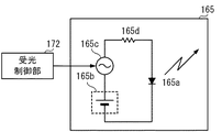
光源部165は、スクリーンに投影する投影光の発光源である。光源部165は、図3に示すように、LED(Light Emitting Diode)165aと、直流電源165bと、AM変調器165cと、抵抗165dと、を備え、投影光の光強度を変調するように構成されている。
The
LED165aは、光を発する発光ダイオードである。直流電源165bは、LED165aに供給する電流の発生源である。AM変調器165cは、直流電源165bがLED165aに供給する電流を、例えば、10MHzの周波数でAM変調を行うことにより、投影光の光強度を変調するものである。AM変調器165cは、AM変調を行った電流を抵抗165dを介してLED165aに供給することにより、投影光の光強度変調を行う。光源部165は、光をSOM162に向けて出射する。
The
投影面傾き計測装置17は、スクリーンの傾き角度を計測するためのものであり、受光部171と、受光制御部172と、演算部173と、からなる。
The projection plane
受光部171は、図4に示すように、スクリーンS上に投影された映像からの反射光R1,R2を受光するものである。
As shown in FIG. 4, the
図5に示すように、プロジェクタ1近傍の投影光Tと反射光R1,R2との間には、時間遅れΔt1,Δt2が発生する。この時間遅れΔt1,Δt2を直接測定することは困難であるため、受光部171は、投影光Tと反射光R1、投影光Tと反射光R2と、の位相のずれ量を検出する。
As shown in FIG. 5, time delays Δt1 and Δt2 occur between the projection light T near the
受光部171には、例えば、特開2006−153773号公報に記載された距離画像センサが用いられる。この距離画像センサは、例えば、100×100個のフォトダイオードが行列配置されて構成されたものである。
For the
この距離画像センサ31が位相のずれ量を検出する原理について説明する。
図6の(a)に示すように、光源部165からの光の強度が曲線イのように変化するものとする。図6の(b)に示すように、この曲線イに対して、受光量が曲線ロのように変化し、曲線イと曲線ロとの位相差(位相のずれ量)がΔφとすると、この位相差Δφが光の飛行時間に相当する。
The principle that the distance image sensor 31 detects the phase shift amount will be described.
As shown in FIG. 6 (a), the intensity of the light from the
この図6の(a)に示す曲線イの位相を基準として、位相0〜90°未満、90°〜180°未満、180°〜270°未満、270°〜360°未満のそれぞれの期間の図6の(b)における受光量A0,A1,A2,A3を求める。受光量A0,A1,A2,A3は、次の式(1)〜(4)によって表される。
A0=A・sin(Δφ)+B ・・・(1)
A1=A・sin(π/2+Δφ)+B ・・・(2)
A2=A・sin(π+Δφ)+B ・・・(3)
A3=A・sin(3π/2+Δφ)+B ・・・(4)
尚、Aは最大光強度、Bは直流成分(外光成分と反射光成分との平均値)を示す。ただし、図6のTwは受光量A0,A1,A2,A3を得るためのそれぞれの受光期間を表している。
Relative to the phase of (a) to show the curve b in FIG. 6, under the phase 0 to 90 °, less than 90 ° to 180 °, less than 180 ° to 270 °, Figure of each period of less than 270 ° to 360 ° Request received light amount A0, A1, A2, A3 of 6 in (b). The received light amounts A0, A1, A2, and A3 are expressed by the following equations (1) to (4).
A0 = A · sin (Δφ) + B (1)
A1 = A · sin (π / 2 + Δφ) + B (2)
A2 = A · sin (π + Δφ) + B (3)
A3 = A · sin (3π / 2 + Δφ) + B (4)
A represents the maximum light intensity, and B represents a direct current component (an average value of the external light component and the reflected light component). However, Tw in FIG. 6 represents the respective light receiving periods for obtaining the received light amounts A0, A1, A2, and A3.
受光制御部172が受光部171を制御することにより、受光部171は、受光量A0〜A3に対応する量の信号電荷を出力する。
When the light
受光制御部172は、さらに、演算部173に対して、投影光と反射光との位相のずれ量Δφ、各測距点までのそれぞれの距離、スクリーンSの傾き角度を取得するように指示する。
The light
演算部173は、理想投影面に対するスクリーンSの傾き角度を取得するものであり、受光制御部172と同様に、ROMと、RAMと、CPUと、を備える(いずれも図示せず)。
The
演算部173は、受光制御部172に指示されて上記処理を実行する。演算部173は、式(5)に従い、受光部171が出力した信号電荷の量に対応する受光量A0〜A3に基づいて位相のずれ量Δφを取得する。
The
図4に示すように、スクリーンS上の2つの測距点までの距離を取得する場合、演算部173は、この2つの測距点に対応する受光部171の画素の受光量A0〜A3を取得し、取得した受光量A0〜A3に基づいて位相のずれ量Δφを取得する。
As shown in FIG. 4, when acquiring the distance to two ranging points on the screen S, the calculating
演算部173は、取得した位相のずれ量Δφに基づいて、時間遅れΔt1,Δt2を取得し、プロジェクタ1とスクリーンS上の複数の点までの距離を演算し、理想投影面に対するスクリーンSの傾き角度を取得する。プロジェクタからスクリーンS上の2点の距離をそれぞれ取得する場合、スクリーンの上下方向の傾斜角度を得て、縦方向の歪み補正が可能となる。
The
位相のずれ量をΔφとすると、時間遅れΔtは、次の式(6)によって表される。

スクリーンSが理想投影面に対して傾いている場合、2つの測距点までの距離が異なるため、反射光R1の時間遅れと反射光R2の時間遅れが異なる。 When the screen S is inclined with respect to the ideal projection plane, the distance to the two distance measuring points is different, so the time delay of the reflected light R1 and the time delay of the reflected light R2 are different.
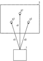
次に、図7は、スクリーンS上の3つの方向で距離を取得する場合のスクリーンS上の3つの測距点p1,p2,p3とプロジェクタ1との位置関係を示す。プロジェクタからスクリーンS上の3点の距離をそれぞれ取得する場合、スクリーンの上下方向の傾斜角度に加え左右方向の傾斜角度も得られるため、縦方向と横方向の歪み補正が可能になる。
Next, FIG. 7 shows the positional relationship between the screen S three distance measuring points on p1, p2, p3 and the
演算部173は、スクリーンS上の3つの測距点p1〜p3を選択し、受光部171が出力した信号電荷のうち、選択した3つの測距点p1〜p3に対応するそれぞれの画素の受光量A0〜A3を取得する。
The
演算部173は、取得したそれぞれの受光量A0〜A3に基づいて、プロジェクタ1から測距点p1〜p3までのそれぞれの距離d1〜d3を式(6)〜(8)に従って求める。演算部173は、これら3つの距離d1〜d3に基づいてスクリーンSの傾き角度を算出する。
The
キー/インジケータ部18は、キーとインジケータとを備えたものであり、キーとして、電源キーと、ズームキーと、フォーカスキーと、「AFK」キーと、入力切換キーと、メニューキーと、操作キーと、を備える(いずれも図示せず)。
The key /
電源キーは、電源のオン/オフするためのキーである。ズームキーは、ズームアップ及びズームダウンを指示するためのキーである。フォーカスキーは、プロジェクタ1に対して合焦位置の前方向及び後方向への移動を指示するためのキーである。
The power key is a key for turning on / off the power. The zoom key is a key for instructing zoom-up and zoom-down. The focus key is a key for instructing the
「AFK」キーは、自動合焦(Automatic Focus)と自動台形補正の即時実行を指示するためのキーである。入力切換キーは、入出力コネクタ部11の画像信号入出力用のコネクタを切換えるためのキーである。
The “AFK” key is a key for instructing immediate execution of automatic focus and automatic keystone correction. The input switching key is a key for switching the image signal input / output connector of the input /
メニューキーは、投影動作に関する各種メニュー項目の表示を指示するためのキーである。操作キーは、カーソルキー等、各種操作を指示するためのキーである。キー/インジケータ部18は、これらのキーが押下されると、この操作情報を制御部20に供給する。
The menu key is a key for instructing display of various menu items related to the projection operation. The operation key is a key for instructing various operations such as a cursor key. The key /
また、キー/インジケータ部18は、インジケータとして、電源/待機インジケータを備える(いずれも図示せず)。電源/待機インジケータは、電源のオン/オフ状態、画像信号の入力がない状態を表示するものであり、例えば、表示用LEDを備える。電源/待機インジケータは、表示用LEDを点灯/消灯、あるいは点滅させることにより、これらの状態を表示する。
The key /
Ir受信部19は、このプロジェクタ1のリモートコントローラ(図示せず)からの操作情報を示す赤外光信号を受信するものである。
The
制御部20は、各部の動作制御を行うためのものであり、受光制御部172と同様に、ROMと、RAMと、CPUと、を備える(いずれも図示せず)。制御部20は、キー/インジケータ部18、Ir受信部19から操作情報が供給されると、この操作情報に基づいて各部を制御する。
The
具体的に、制御部20は、キー/インジケータ部18から、電源キーが押下された旨の操作情報が供給される毎に、プロジェクタ1の電源をオン、オフする。
Specifically, the
制御部20は、キー/インジケータ部18から、「AFK」キーが押下された旨の操作情報が供給されと、投影面傾き計測装置17に、スクリーンSまでの距離を計測するように指示する。そして、投影面傾き計測装置17から距離情報が供給されると、制御部20は、この距離情報に基づいてレンズモータ164を駆動して自動合焦を行う。
When the operation information indicating that the “AFK” key has been pressed is supplied from the key /
また、制御部20は、投影面傾き計測装置17からスクリーンSの傾き角度が供給されると、画像処理部13に、このスクリーンSの傾き角度を供給して、自動台形補正を行うように指示する。
In addition, when the tilt angle of the screen S is supplied from the projection plane
画像記憶部21は、作業に必要な画像データを記憶するためのものであり、例えばフラッシュメモリ等からなる。制御部20は、画像記憶部21に記憶された画像データを読出して表示エンコーダ15へ送出し、読み出した画像データに基づく画像を投影させる。
The
スピーカ22は、音声を出力するためのものである。音声処理部23は、PCM音源等の音源回路を備え、投影表示動作時に与えられる音声データをアナログ化し、スピーカ22を駆動して拡声放音させるためのものである。
The
次に本実施形態に係るプロジェクタ1の動作を説明する。
キー/インジケータ部18の電源キーが押下されると、キー/インジケータ部18は、この操作情報を制御部20に供給し、制御部20は、この操作情報に基づいてプロジェクタ1の電源をオンする。
Next, the operation of the
When the power key of the key /
プロジェクタ1に画像信号が供給されると、画像処理部13は、供給された画像信号をシステムバスSBを介して取得し、取得した画像信号を予め設定されたフォーマットの画像信号に変換する。
When an image signal is supplied to the
表示エンコーダ15は、画像処理部13が変換した画像信号を展開して、ビデオRAM14に記憶し、ビデオRAM14に展開記憶した画像信号から、ビデオ信号を生成し、生成したビデオ信号を投影部16の表示駆動部161に供給する。
The
表示駆動部161は、表示エンコーダ15から供給された画像信号に対応するように、30[フレーム/秒]のフレームレートでSOM162を色毎に時分割で表示駆動する。
The
光源部165がこのSOM162に光を照射すると、SOM162は、照射された光を反射する。SOM162で反射した光像は、投影レンズ163を介してスクリーンSに投影される。
When the
「AFK」キーが押下されると、キー/インジケータ部18は、この操作情報を制御部20に供給し、制御部20は、受光制御部172に、傾き計測制御処理を実行するように指示する。
When the “AFK” key is pressed, the key /
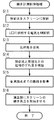
受光制御部172は、内蔵するROMから傾き計測制御処理の処理プログラムを読み出して、図8に示すフローチャートに従って、この傾き計測制御処理を実行する。
Receiving
受光制御部172は、投影光をスクリーンSに投影するように投影部16を制御する(ステップS11)。
The light
受光制御部172は、LED165aに供給する電流をAM変調するようにAM変調器165cを制御する(ステップS12)。
The light
受光制御部172は、反射光を受光するように受光部171を制御する(ステップS13)。
The light
受光制御部172は、受光部171が出力した信号電荷の量に基づいて、演算部173に各演算を行うように指示する。演算部173は、この指示に従い、式(5)により、投影光Tと反射光R1,R2との位相のずれ量Δφを検出する(ステップS14)。
The light
演算部173は、各測距点までのそれぞれの距離を取得する(ステップS15)。
演算部173は、スクリーンSの傾き角度を取得する(ステップS16)。
The
演算部173は、図7に示すスクリーンS上の3つの測距点p1〜p3を選択し、受光部171が出力した信号電荷のうち、選択した3つの測距点p1〜p3に対応するそれぞれの画素の受光量A0〜A3を取得する。
The
演算部173は、式(5)に従い、受光部171が取得した3つの画素のそれぞれの受光量A0〜A3に基づいて、位相のずれ量Δφを検出する(ステップS14の処理)。
また、演算部173は、式(8)に従い、取得した位相のずれ量Δφに基づいて距離d1〜d3を取得する(ステップS15の処理)。
The
演算部173は、演算した距離d1〜d3に基づいてスクリーンSの傾き角度を取得する(ステップS16の処理)。
このように、受光制御部172、演算部173が傾き計測制御処理を実行すると、投影面傾き計測装置17は、演算部173が演算した結果の距離d1〜d3、スクリーンSの傾き角度を制御部20に供給する。
As described above, when the light
制御部20は、投影面傾き計測装置17から供給された距離d1〜d3に基づいて、レンズモータ164を制御して、自動合焦を行う。
The
また、制御部20は、投影面傾き計測装置17から供給されたスクリーンSの傾き角度を画像処理部13に供給し、自動台形補正を行うように指示する。
Further, the
画像処理部13は、供給されたスクリーンSの傾き角度に基づいて変換パラメータを取得する。そして、画像処理部13は、システムバスSBを介して取得した画像信号に対して、この変換パラメータを用いて自動台形補正を行う。スクリーンSには、スクリーンSが傾いていたとしても、あたかも正面からみた画像が表示される。
The
以上説明したように、本実施形態によれば、光源部165は、投影光に対して光強度変調を行い、プロジェクタ1は、光強度変調を行った投影光をスクリーンSに投影する。投影面傾き計測装置17の受光部171は、スクリーンS上の3つの測距点p1〜p3からの投影光の反射光を受光して、投影光に対する反射光の位相のずれ量Δφを検出する。
As described above, according to the present embodiment, the
演算部173は、この位相のずれ量Δφに基づいて、時間遅れΔtを取得し、プロジェクタ1とスクリーンS上の3つの測距点p1〜p3の距離情報を取得し、スクリーンSの傾き角度を取得するようにした。そして、画像処理部13は、このスクリーンSの傾き角度に基づいて自動台形補正を行うようにした。
The
従って、位相のずれ量Δφに基づいて、スクリーンSの測距点p1〜p3の距離を取得するため、プロジェクタ1は、三角測距法と比較して、精度良くスクリーンSの傾き角度を取得することができる。
Therefore, since the distance between the distance measurement points p1 to p3 of the screen S is acquired based on the phase shift amount Δφ, the
このため、プロジェクタ1は、自動台形補正の精度を向上させることができ、測距のための光学変調素子が不要となり、測距専用の光源も不要となり、プロジェクタ1を小型化することができる。
Therefore, the
尚、本発明を実施するにあたっては、種々の形態が考えられ、上記実施形態に限られるものではない。
例えば、上記実施形態では、光源部165のAM変調器165cが行うAM変調の変調周波数は、10MHzに限られるものではなく、さらに、高い変調周波数、あるいは、10MHz未満の変調周波数であってもよい。
In carrying out the present invention, various forms are conceivable and the present invention is not limited to the above embodiment.
For example, in the above embodiment, the modulation frequency of AM modulation performed by the
上記実施形態では、光源部165の発光源としては、LED165aに限られるものではなく、レーザであってもよい。レーザ光であってもAM変調は可能である。但し、レーザを用いる場合には、レーザ光を拡散するためのレンズを備える必要がある。
In the above embodiment, the light source of the
また、上記実施形態では、光源部165にAM変調器165cを備えるようにした。しかし、光源部165にAM変調器165cを備える代わりに、表示駆動部161がSOM162を制御して投影光をAM変調するような構成であってもよい。また、投影レンズ163に光量調整部を備え、この光量調節部が投影光に対する光強度変調を行うような構成であってもよい。
In the above embodiment, the
上記実施形態では、投影面傾き計測装置17は受光部子171として、距離画像センサ31を備えるようにした。しかし、受光部171は、距離画像センサ31に限られるものではなく、アバランシェフォトダイオードであってもよい。但し、受光部171に距離画像センサ31を用いた方が1つのセンサで細かい設定を行うことができる。
In the above embodiment, the projection plane
上記実施形態では、キー/インジケータ部18の「AFK」キーが押下されたときに、プロジェクタ1は、自動台形補正を行うようにした。しかし、「AFK」キーが押下されなくても、プロジェクタ1は、測距を定期的に実行し、台形補正を完全自動で実行するようにしてもよい。
In the above embodiment, when the “AFK” key of the key /
上記実施形態では、投影面傾き計測装置17がスクリーンSの傾き角度を計測するものとして説明した。しかし、投影面傾き計測装置17は、スクリーンSまでの距離を取得するだけのものであってもよい。
In the above-described embodiment, the projection plane
この場合も、プロジェクタ1は、スクリーンSの傾きを計測する場合と同様に動作する。但し、受光部171は、フォトダイオードを1つ備えるだけでよいし、スクリーンS上の測距点も1つだけでよい。
Also in this case, the
上記実施形態では、プログラムが、それぞれメモリ等に予め記憶されているものとして説明した。しかし、プロジェクタを、装置の全部又は一部として動作させ、あるいは、上述の処理を実行させるためのプログラムを、フレキシブルディスク、CD−ROM(Compact Disk Read-Only Memory)、DVD(Digital Versatile Disk)、MO(Magneto Optical disk)などのコンピュータ読み取り可能な記録媒体に格納して配布し、これを別のコンピュータにインストールし、上述の手段として動作させ、あるいは、上述の工程を実行させてもよい。 In the above-described embodiment, the program is described as being stored in advance in a memory or the like. However, a program for operating the projector as the whole or a part of the apparatus or executing the above-described processing is a flexible disk, a CD-ROM (Compact Disk Read-Only Memory), a DVD (Digital Versatile Disk), The information may be stored in a computer-readable recording medium such as an MO (Magneto Optical disk) and distributed, installed in another computer, operated as the above-described means, or the above-described steps may be executed.
さらに、インターネット上のサーバ装置が有するディスク装置等にプログラムを格納しておき、例えば、搬送波に重畳させて、コンピュータにダウンロード等するものとしてもよい。 Furthermore, the program may be stored in a disk device or the like included in a server device on the Internet, and may be downloaded onto a computer by being superimposed on a carrier wave, for example.
1・・・プロジェクタ、16・・・投影部、165・・・光源部、17・・・投影面傾き計測装置、31・・・距離画像センサ、171・・・受光部、172・・・受光制御部、173・・・演算部
DESCRIPTION OF
Claims (10)
前記投影部が投影する前記投影光の光強度を変調する光変調部と、
前記投影部が投影した投影光が投影面で反射した反射光を受光する受光部と、
前記光変調部が光変調した前記投影光と前記受光部が受光した反射光との位相のずれ量を検出し、検出した位相のずれ量に基づいて、前記投影レンズから前記投影面までの距離を取得する測距部と、を備え、
前記投影部は、画像投影時に、前記光源と前記SOMによって生成される投影光を前記投影レンズによって投影し、
前記測距部は、投影面までの距離を測距する際に、前記受光部が受光する前記光源と前記光変調部と前記SOMと前記投影レンズとによって投影される投影光の反射光に基づいて、前記投影レンズから前記投影面までの距離を取得する
ことを特徴とするプロジェクタ。 A projection unit that projects projection light onto a projection surface and includes a light source, a SOM, and a projection lens ;
A light modulation unit that modulates the light intensity of the projection light projected by the projection unit;
A light receiving unit that receives the reflected light reflected by the projection surface by the projection light projected by the projection unit;
The amount of phase shift between the projection light modulated by the light modulation unit and the reflected light received by the light receiving unit is detected, and the distance from the projection lens to the projection plane based on the detected phase shift amount and a distance measuring unit for acquiring,
The projection unit projects projection light generated by the light source and the SOM by the projection lens during image projection,
The distance measuring unit is based on reflected light of projection light projected by the light source, the light modulation unit, the SOM, and the projection lens received by the light receiving unit when measuring the distance to the projection surface. And obtaining a distance from the projection lens to the projection plane .
前記投影部が投影する前記投影光の光強度を変調する光変調部と、
前記投影部が投影した投影光が投影面で反射した反射光を、複数の受光点に配置された複数の受光素子で受光する受光部と、
前記光変調部が光変調した前記投影光と前記受光部の複数の受光素子が受光した反射光との位相のずれ量を検出し、検出した位相のずれ量に基づいて、前記投影レンズから前記投影面の複数の点までの距離を取得する測距部と、
前記測距部が取得した複数の距離に基づいて、前記投影光の光軸に垂直な理想投影面に対する前記投影面の傾き角度を取得する投影面傾き角度取得部と、を備え、
前記投影部は、画像投影時に、前記光源と前記SOMによって生成される投影光を前記投影レンズによって投影し、
前記測距部は、投影面までの距離を測距する際に、前記受光部が受光する前記光源と前記光変調部と前記SOMと前記投影レンズとによって投影される投影光の反射光に基づいて、前記投影レンズから前記投影面までの距離を取得する
ことを特徴とするプロジェクタ。 A projection unit that projects projection light onto a projection surface and includes a light source, a SOM, and a projection lens ;
A light modulation unit that modulates the light intensity of the projection light projected by the projection unit;
A light receiving unit that receives the reflected light reflected by the projection surface by the projection unit by a plurality of light receiving elements arranged at a plurality of light receiving points;
A phase shift amount between the projection light modulated by the light modulation unit and reflected light received by the plurality of light receiving elements of the light receiving unit is detected, and from the projection lens , the phase shift amount is detected based on the detected phase shift amount. A distance measuring unit for acquiring distances to a plurality of points on the projection plane;
A projection plane inclination angle acquisition unit that acquires an inclination angle of the projection plane with respect to an ideal projection plane perpendicular to the optical axis of the projection light based on a plurality of distances acquired by the distance measurement unit ;
The projection unit projects projection light generated by the light source and the SOM by the projection lens during image projection,
The distance measuring unit is based on reflected light of projection light projected by the light source, the light modulation unit, the SOM, and the projection lens received by the light receiving unit when measuring the distance to the projection surface. And obtaining a distance from the projection lens to the projection plane .
前記光変調部は、前記光源に供給する電流のAM変調を行うことにより、前記投影光の光強度を変調する、
ことを特徴とする請求項1又は2に記載のプロジェクタ。 The projection unit includes a light source that is supplied with current and generates the projection light,
The light modulation unit modulates the light intensity of the projection light by performing AM modulation of a current supplied to the light source,
The projector according to claim 1, wherein the projector is a projector.
ことを特徴とする請求項3に記載のプロジェクタ。 The light source is constituted by a light emitting diode,
The projector according to claim 3.
ことを特徴とする請求項3に記載のプロジェクタ。 The light source is constituted by a laser;
The projector according to claim 3.
ことを特徴とする請求項2に記載のプロジェクタ。 The light receiving unit is configured by a distance image sensor in which a plurality of light receiving elements are arranged in a matrix, and distances to a plurality of points on the projection surface are acquired based on a light reception amount of light received by each light receiving element. is there,
The projector according to claim 2.
前記投影光の光強度を変調する光変調ステップと、
前記投影面で反射した反射光を受光する受光ステップと、
前記投影光と前記反射光との位相のずれ量を検出する検出ステップと、
前記検出した位相のずれ量に基づいて、前記投影レンズから前記投影面までの距離を取得する距離算出ステップと、を備え、
前記投影ステップにおける画像投影時に、前記光源と前記SOMによって生成される投影光を前記投影レンズによって投影し、
前記測距ステップにおける測距時に、前記投影ステップと前記光変調ステップと前記受光ステップとを用いて、前記光源と前記光変調ステップと前記SOMとによって生成した投影光を前記投影レンズによって投影すると共に、前記受光ステップで反射光を受光して前記投影レンズから前記投影面までの距離を取得する
ことを特徴とするプロジェクタの距離計測方法。 A projection step of projecting projection light onto a projection surface via a light source, a SOM, and a projection lens ;
A light modulation step for modulating the light intensity of the projection light;
A light receiving step for receiving reflected light reflected by the projection surface;
A detection step of detecting a phase shift amount between the projection light and the reflected light;
A distance calculating step for obtaining a distance from the projection lens to the projection plane based on the detected phase shift amount ; and
At the time of image projection in the projection step, the projection light generated by the light source and the SOM is projected by the projection lens,
During the distance measurement in the distance measuring step, the projection light generated by the light source, the light modulation step, and the SOM is projected by the projection lens using the projection step, the light modulation step, and the light receiving step. A distance measurement method for a projector , wherein reflected light is received in the light receiving step to obtain a distance from the projection lens to the projection plane .
前記投影光の光強度を変調する光変調ステップと、
前記投影面で反射した反射光を複数の受光点で受光する受光ステップと、
前記投影光と各受光点で受光した反射光との位相のずれ量を検出する検出ステップと、
前記検出した位相のずれ量に基づいて、前記投影レンズから前記投影面上の複数の点までのそれぞれの距離を取得する距離算出ステップと、
取得した前記投影面までのそれぞれの距離に基づいて、前記投影光の光軸に垂直な理想投影面に対する前記投影面の傾き角度を取得する傾斜角取得ステップと、を備え、
前記測距ステップにおける測距時に、前記投影ステップと前記光変調ステップと前記受光ステップとを用いて、前記光源と前記光変調ステップと前記SOMとによって生成した投影光を前記投影レンズによって投影すると共に、前記受光ステップで反射光を受光して前記投影レンズから前記投影面までの距離を取得する
ことを特徴とするプロジェクタの投影面傾き取得方法。 A projection step of projecting projection light onto a projection surface via a light source, a SOM, and a projection lens ;
A light modulation step for modulating the light intensity of the projection light;
A light receiving step of receiving reflected light reflected by the projection surface at a plurality of light receiving points;
A detection step of detecting a phase shift amount between the projection light and the reflected light received at each light receiving point;
A distance calculating step for acquiring respective distances from the projection lens to a plurality of points on the projection plane based on the detected phase shift amount;
An inclination angle acquisition step of acquiring an inclination angle of the projection plane with respect to an ideal projection plane perpendicular to the optical axis of the projection light based on the acquired distances to the projection plane ; and
During the distance measurement in the distance measuring step, the projection light generated by the light source, the light modulation step, and the SOM is projected by the projection lens using the projection step, the light modulation step, and the light receiving step. A projection plane inclination acquisition method for a projector , wherein reflected light is received in the light reception step to acquire a distance from the projection lens to the projection plane.
光源、SOM、投影レンズを介して投影面に投影光を投影する投影手順、
前記投影光の光強度を変調する光変調手順、
前記投影面で反射した反射光を受光する受光手順、
前記投影光と前記反射光との位相のずれ量を検出する検出手順、
前記光源と前記光変調手順と前記SOMとによって生成した投影光を前記投影レンズによって投影すると共に、前記受光手順で反射光を受光して、前記検出手順で検出した位相のずれ量に基づいて、前記投影レンズから前記投影面までの距離を取得する距離算出手順、
を実行させるためのプログラム。 On the computer,
Projection procedure for projecting projection light onto a projection surface via a light source, SOM, and projection lens ,
A light modulation procedure for modulating the light intensity of the projection light;
A light receiving procedure for receiving reflected light reflected by the projection surface;
A detection procedure for detecting a phase shift amount between the projection light and the reflected light;
Projecting the projection light generated by the light source, the light modulation procedure and the SOM by the projection lens, receiving the reflected light by the light reception procedure, and based on the phase shift amount detected by the detection procedure, A distance calculation procedure for obtaining a distance from the projection lens to the projection plane ;
A program for running
光源、SOM、投影レンズを介して投影面に投影光を投影する投影手順、
前記投影光の光強度を変調する光変調手順、
前記投影面で反射した反射光を複数の受光点で受光する受光手順、
前記投影光と各受光点で受光した反射光との位相のずれ量を検出する検出手順、
前記光源と前記光変調手順と前記SOMとによって生成した投影光を前記投影レンズによって投影すると共に、前記受光手順で反射光を受光して、前記検出手順で検出した位相のずれ量に基づいて、前記投影レンズから前記投影面上の複数の点までのそれぞれの距離を取得する距離算出手順、
取得した前記投影面までのそれぞれの距離に基づいて、前記投影光の光軸に垂直な理想投影面に対する前記投影面の傾き角度を取得する傾斜角取得手順、
を実行させるためのプログラム。 On the computer,
Projection procedure for projecting projection light onto a projection surface via a light source, SOM, and projection lens ,
A light modulation procedure for modulating the light intensity of the projection light;
A light receiving procedure for receiving reflected light reflected by the projection surface at a plurality of light receiving points;
A detection procedure for detecting an amount of phase shift between the projection light and the reflected light received at each light receiving point;
Projecting the projection light generated by the light source, the light modulation procedure and the SOM by the projection lens, receiving the reflected light by the light reception procedure, and based on the phase shift amount detected by the detection procedure, A distance calculation procedure for acquiring respective distances from the projection lens to a plurality of points on the projection plane;
An inclination angle acquisition procedure for acquiring an inclination angle of the projection plane with respect to an ideal projection plane perpendicular to the optical axis of the projection light, based on the acquired distance to the projection plane,
A program for running
Priority Applications (2)
| Application Number | Priority Date | Filing Date | Title |
|---|---|---|---|
| JP2006221182A JP4872525B2 (en) | 2006-08-14 | 2006-08-14 | Projector, projector distance measurement method, projector projection plane tilt acquisition method, and program |
| US11/891,564 US7667825B2 (en) | 2006-08-14 | 2007-08-10 | Projector, method of measuring distance to the projector, and method and program for acquiring inclination angles of projection screen |
Applications Claiming Priority (1)
| Application Number | Priority Date | Filing Date | Title |
|---|---|---|---|
| JP2006221182A JP4872525B2 (en) | 2006-08-14 | 2006-08-14 | Projector, projector distance measurement method, projector projection plane tilt acquisition method, and program |
Publications (3)
| Publication Number | Publication Date |
|---|---|
| JP2008046314A JP2008046314A (en) | 2008-02-28 |
| JP2008046314A5 JP2008046314A5 (en) | 2009-09-24 |
| JP4872525B2 true JP4872525B2 (en) | 2012-02-08 |
Family
ID=39050399
Family Applications (1)
| Application Number | Title | Priority Date | Filing Date |
|---|---|---|---|
| JP2006221182A Expired - Fee Related JP4872525B2 (en) | 2006-08-14 | 2006-08-14 | Projector, projector distance measurement method, projector projection plane tilt acquisition method, and program |
Country Status (2)
| Country | Link |
|---|---|
| US (1) | US7667825B2 (en) |
| JP (1) | JP4872525B2 (en) |
Cited By (1)
| Publication number | Priority date | Publication date | Assignee | Title |
|---|---|---|---|---|
| EP2816455A1 (en) | 2013-06-18 | 2014-12-24 | Funai Electric Co., Ltd. | Projector with photodetector for inclination calculation of an object |
Families Citing this family (7)
| Publication number | Priority date | Publication date | Assignee | Title |
|---|---|---|---|---|
| JP2010085133A (en) * | 2008-09-30 | 2010-04-15 | Casio Computer Co Ltd | Distance measuring apparatus, distance measuring method, and projector |
| JP6011157B2 (en) * | 2011-09-05 | 2016-10-19 | 株式会社リコー | Projection system, projection device, sensor device, power generation control method, and power generation control program |
| WO2018167999A1 (en) * | 2017-03-17 | 2018-09-20 | パナソニックIpマネジメント株式会社 | Projector and projector system |
| JP7008244B2 (en) * | 2017-07-11 | 2022-01-25 | パナソニックIpマネジメント株式会社 | Projection type image display device |
| CN108762483B (en) * | 2018-04-16 | 2021-02-09 | 广景视睿科技(深圳)有限公司 | Interactive projector and interactive projection method |
| DE102019003049B4 (en) * | 2019-04-27 | 2021-04-29 | Tarsier Gmbh | Device and method for detecting objects |
| US20230418145A1 (en) * | 2020-11-25 | 2023-12-28 | Panasonic Intellectual Property Management Co., Ltd. | Projection device |
Family Cites Families (11)
| Publication number | Priority date | Publication date | Assignee | Title |
|---|---|---|---|---|
| JPH0728166A (en) * | 1993-07-14 | 1995-01-31 | Mitsubishi Electric Corp | Video projector device |
| US7194112B2 (en) * | 2001-03-12 | 2007-03-20 | Eastman Kodak Company | Three dimensional spatial panorama formation with a range imaging system |
| JP4810763B2 (en) * | 2001-06-20 | 2011-11-09 | 株式会社デンソー | Distance measuring device |
| JP2005006228A (en) * | 2003-06-13 | 2005-01-06 | Casio Comput Co Ltd | Projector |
| JP2005024523A (en) * | 2003-07-04 | 2005-01-27 | Nec Viewtechnology Ltd | Range finder and projector having range finder |
| JP4155890B2 (en) * | 2003-07-15 | 2008-09-24 | カシオ計算機株式会社 | Projector, projector tilt angle acquisition method, and projection image correction method |
| JP3757224B2 (en) * | 2003-09-03 | 2006-03-22 | Necビューテクノロジー株式会社 | Projector having tilt angle measuring device |
| JP3761550B2 (en) * | 2003-09-24 | 2006-03-29 | Necビューテクノロジー株式会社 | Projector having reflected light intensity measurement mechanism |
| JP4725021B2 (en) * | 2004-02-13 | 2011-07-13 | カシオ計算機株式会社 | Projection apparatus and light source control method for projection apparatus |
| JP2005233880A (en) | 2004-02-23 | 2005-09-02 | Casio Comput Co Ltd | Distance measuring instrument, projector, distance measuring method, and program |
| JP2005331585A (en) * | 2004-05-18 | 2005-12-02 | Nec Viewtechnology Ltd | Projector having device for measuring distance and tilt angle |
-
2006
- 2006-08-14 JP JP2006221182A patent/JP4872525B2/en not_active Expired - Fee Related
-
2007
- 2007-08-10 US US11/891,564 patent/US7667825B2/en active Active
Cited By (2)
| Publication number | Priority date | Publication date | Assignee | Title |
|---|---|---|---|---|
| EP2816455A1 (en) | 2013-06-18 | 2014-12-24 | Funai Electric Co., Ltd. | Projector with photodetector for inclination calculation of an object |
| US9405407B2 (en) | 2013-06-18 | 2016-08-02 | Funai Electric Co., Ltd. | Projector |
Also Published As
| Publication number | Publication date |
|---|---|
| US7667825B2 (en) | 2010-02-23 |
| US20080036995A1 (en) | 2008-02-14 |
| JP2008046314A (en) | 2008-02-28 |
Similar Documents
| Publication | Publication Date | Title |
|---|---|---|
| JP4872525B2 (en) | Projector, projector distance measurement method, projector projection plane tilt acquisition method, and program | |
| JP3772870B2 (en) | Projection apparatus, projection method, and program | |
| JP4020043B2 (en) | Projection apparatus, projection method, and program | |
| JP4609734B2 (en) | Distance measuring device and projector provided with the distance measuring device | |
| JP4023447B2 (en) | Projection apparatus, projection method, and program | |
| JP5124965B2 (en) | Projection apparatus, projection method, and program | |
| JP6387644B2 (en) | Position detection device, position detection system, and position detection method | |
| JP6441966B2 (en) | Laser projection display device and control method of laser light source driving unit used therefor | |
| JP2008233550A (en) | Projector apparatus, projection control method and program | |
| JP5246467B2 (en) | Distance measuring device and projector | |
| JP2001045381A (en) | Picture processor and picture processing method and medium | |
| JP2007065542A (en) | Image projection device | |
| JP5500786B2 (en) | Projection display | |
| JP4301028B2 (en) | Projection apparatus, angle detection method, and program | |
| JP5140973B2 (en) | Measuring surface tilt measuring device, projector and measuring surface tilt measuring method | |
| JP5292678B2 (en) | Projector, pointer display processing method, and program | |
| JP4661161B2 (en) | Projection apparatus, projection method, and program | |
| JP5125561B2 (en) | Projection apparatus and projection control method | |
| JP2008020196A (en) | Projector, ranging method and program of projector | |
| JP5504697B2 (en) | Projection system, projection apparatus, audio control method, and program | |
| JP2004363856A (en) | Projection type display device | |
| JP2012233920A (en) | Measurement surface inclination measuring device, projector, and measurement surface inclination measuring method | |
| JP4556944B2 (en) | Projection apparatus, distance measurement processing method, and program | |
| JP2005233880A (en) | Distance measuring instrument, projector, distance measuring method, and program | |
| JP4442242B2 (en) | Projection apparatus, angle detection method, and program |
Legal Events
| Date | Code | Title | Description |
|---|---|---|---|
| A521 | Request for written amendment filed |
Free format text: JAPANESE INTERMEDIATE CODE: A523 Effective date: 20090807 |
|
| A621 | Written request for application examination |
Free format text: JAPANESE INTERMEDIATE CODE: A621 Effective date: 20090807 |
|
| TRDD | Decision of grant or rejection written | ||
| A01 | Written decision to grant a patent or to grant a registration (utility model) |
Free format text: JAPANESE INTERMEDIATE CODE: A01 Effective date: 20111025 |
|
| A01 | Written decision to grant a patent or to grant a registration (utility model) |
Free format text: JAPANESE INTERMEDIATE CODE: A01 |
|
| A61 | First payment of annual fees (during grant procedure) |
Free format text: JAPANESE INTERMEDIATE CODE: A61 Effective date: 20111107 |
|
| FPAY | Renewal fee payment (event date is renewal date of database) |
Free format text: PAYMENT UNTIL: 20141202 Year of fee payment: 3 |
|
| R150 | Certificate of patent or registration of utility model |
Ref document number: 4872525 Country of ref document: JP Free format text: JAPANESE INTERMEDIATE CODE: R150 Free format text: JAPANESE INTERMEDIATE CODE: R150 |
|
| LAPS | Cancellation because of no payment of annual fees |