JP4871794B2 - Printing apparatus and printing method - Google Patents
Printing apparatus and printing method Download PDFInfo
- Publication number
- JP4871794B2 JP4871794B2 JP2007160339A JP2007160339A JP4871794B2 JP 4871794 B2 JP4871794 B2 JP 4871794B2 JP 2007160339 A JP2007160339 A JP 2007160339A JP 2007160339 A JP2007160339 A JP 2007160339A JP 4871794 B2 JP4871794 B2 JP 4871794B2
- Authority
- JP
- Japan
- Prior art keywords
- information
- embedded
- data
- embedding
- Prior art date
- Legal status (The legal status is an assumption and is not a legal conclusion. Google has not performed a legal analysis and makes no representation as to the accuracy of the status listed.)
- Expired - Fee Related
Links
Images


Classifications
-
- G—PHYSICS
- G06—COMPUTING; CALCULATING OR COUNTING
- G06K—GRAPHICAL DATA READING; PRESENTATION OF DATA; RECORD CARRIERS; HANDLING RECORD CARRIERS
- G06K17/00—Methods or arrangements for effecting co-operative working between equipments covered by two or more of main groups G06K1/00 - G06K15/00, e.g. automatic card files incorporating conveying and reading operations
-
- G—PHYSICS
- G06—COMPUTING; CALCULATING OR COUNTING
- G06K—GRAPHICAL DATA READING; PRESENTATION OF DATA; RECORD CARRIERS; HANDLING RECORD CARRIERS
- G06K15/00—Arrangements for producing a permanent visual presentation of the output data, e.g. computer output printers
- G06K15/02—Arrangements for producing a permanent visual presentation of the output data, e.g. computer output printers using printers
- G06K15/18—Conditioning data for presenting it to the physical printing elements
- G06K15/1848—Generation of the printable image
- G06K15/1852—Generation of the printable image involving combining data of different types
Description
本発明は、電子ドキュメントを印刷する装置等であって、当該電子ドキュメントを印刷すると共に当該電子ドキュメントに関する情報を埋込印刷する印刷装置等に関する。 The present invention relates to an apparatus for printing an electronic document, and the like, which relates to a printing apparatus for printing the electronic document and embedding information about the electronic document.
アプリケーションプログラムを用いて作成した電子ドキュメントを印刷する際に、印刷画像に機械認識可能な符号(埋込符号)を埋込、印刷するシステムが知られている。このシステムは、例えば、電子ドキュメントに関する付加情報(以下、埋込情報という。)を受け取り、埋込情報を埋込符号に変換した後、印刷指示された電子ドキュメントと共に当該埋込符号を用紙に印刷出力する。この用紙をコピーする場合、用紙をスキャナで読み取り走査することにより埋込符号を検出し、検出した埋込符号から埋込情報を求め、その埋込情報に従って印刷処理が行われる。 2. Description of the Related Art A system is known that embeds and prints a machine-recognizable code (embedded code) in a printed image when printing an electronic document created using an application program. For example, this system receives additional information (hereinafter referred to as embedding information) related to an electronic document, converts the embedding information into an embedding code, and then prints the embedding code on a sheet together with the electronic document instructed to be printed. Output. When copying this sheet, the embedded code is detected by reading and scanning the sheet with a scanner, the embedded information is obtained from the detected embedded code, and printing processing is performed according to the embedded information.
一方、印刷設定情報に応じて埋込処理を行う技術も知られている。例えば、特許文献1には、N−up印刷の指定がされ、印刷画像を縮小する場合でも、印刷画像の縮小率に関わらず埋込符号の印刷サイズを一定にすることで、埋込符号の読取処理の誤認識を防止する技術が開示されている。ここで、N−up印刷とは、プリントコストやファイリングスペースを削減するため、1枚の用紙に複数ページの文書をまとめて縮小印刷する機能である。
On the other hand, a technique for performing an embedding process according to print setting information is also known. For example, in
上記の印刷システムにおいては、印刷時の埋込符号の生成処理や、印刷後のスキャナによる読み取り走査/認識処理の高速化を実現するためには、埋込情報の最適化が望まれる。しかし、従来技術の場合、N−up印刷の際に、ページごとに、埋込情報から埋込符号を生成している。そのため、従来技術には、以下に述べる課題がある。 In the printing system described above, it is desired to optimize the embedded information in order to realize the processing for generating the embedded code at the time of printing and the speed of the scanning / recognition processing by the scanner after printing. However, in the case of the prior art, an embedded code is generated from embedded information for each page during N-up printing. For this reason, the conventional techniques have the following problems.
ページ共通の情報があったとしても、ページごとに個別に埋込符号を生成するため、ページ共通の情報が各ページに繰り返し埋込まれる。 Even if there is information common to the pages, the embedding code is individually generated for each page, so that the information common to the pages is repeatedly embedded in each page.
Nページ分の埋込符号を生成するため、埋込情報の管理を行うために用いる制御情報等が冗長になる。 Since the embedded codes for N pages are generated, the control information used for managing the embedded information becomes redundant.
そこで、本発明は、N−up印刷時において、各ページの埋込情報を1つに統合することにより埋込情報の最適化を図り、それにより、埋込情報の埋込処理及び埋込情報の読取処理の高速化、効率化を実現することを目的とする。 Therefore, the present invention optimizes embedding information by integrating the embedding information of each page into one during N-up printing, thereby embedding processing of embedding information and embedding information. An object of the present invention is to realize high-speed and efficient reading processing.
本発明の印刷装置は、印刷データのうちのNページ分を1枚のシートに印刷するためのデータを生成する印刷装置において、前記印刷データ内の各ページに対応付けられている、N−up指定を含む各埋込情報を取得する手段と、取得した前記各埋込情報を解析し、前記N−up指定においてNが2以上であるかどうかを判定する手段と、前記N−up指定においてNが2以上であると判定された場合、前記1枚のシートに印刷されるNページの夫々に対応付けられている埋込情報を統合する手段と、前記シートの印刷領域の全面に周期的に並んだ複数の第2領域と当該第2の領域内に周期的に並んだ複数の第1の領域とによって構成され、当該第1及び第2の領域のそれぞれにおいて仮想的な格子の交点からずれて配置されたドットの位置によって情報が符号化される符号画像であって、前記第1の領域に埋め込まれる情報は複写時にリアルタイムで抽出しなければならない情報であり、前記第2の領域に埋め込まれる情報は複写時にリアルタイムで抽出しなくてもよい情報であり、前記第1の領域に埋め込まれる情報量は前記第2の領域に埋め込まれる情報量よりも少ない、符号画像を、前記統合された埋込情報を用いて生成する手段と、前記Nページ分を1枚のシートに印刷するためのデータに、生成した前記符号画像を合成する手段と を備えることを特徴とする。 Printing apparatus of the present invention is a printing apparatus for generating data for printing N pages of the print data on a sheet, is associated with each page in the print data, N- It means for obtaining the embedded information containing up designation, analyzes the acquired respective embedded information, and means for determining whether N is 2 or more in the N-up designation, the N-up designation When N is determined to be 2 or more, a means for integrating embedding information associated with each of the N pages printed on the one sheet and a period over the entire print area of the sheet A plurality of second regions arranged side by side and a plurality of first regions periodically arranged in the second region, and an intersection of virtual lattices in each of the first and second regions The position of the dot placed off Therefore, in the code image in which information is encoded, the information embedded in the first area is information that must be extracted in real time at the time of copying, and the information embedded in the second area is in real time at the time of copying. It is information that does not need to be extracted, and the amount of information embedded in the first region is smaller than the amount of information embedded in the second region, and a code image is generated using the integrated embedded information means for, said N pages to data to be printed on one sheet, characterized in that it comprises a means for combining the generated the code image.
本発明の印刷方法は、印刷データのうちのNページ分を1枚のシートに印刷するためのデータを生成する印刷方法において、前記印刷データ内の各ページに対応付けられている、N−up指定を含む各埋込情報を取得するステップと、取得した前記各埋込情報を解析し、前記N−up指定においてNが2以上であるかどうかを判定するステップと、前記N−up指定においてNが2以上であると判定された場合、前記1枚のシートに印刷されるNページの夫々に対応付けられている埋込情報を統合するステップと、前記シートの印刷領域の全面に周期的に並んだ複数の第2領域と当該第2の領域内に周期的に並んだ複数の第1の領域とによって構成され、当該第1及び第2の領域のそれぞれにおいて仮想的な格子の交点からずれて配置されたドットの位置によって情報が符号化される符号画像であって、前記第1の領域に埋め込まれる情報は複写時にリアルタイムで抽出しなければならない情報であり、前記第2の領域に埋め込まれる情報は複写時にリアルタイムで抽出しなくてもよい情報であり、前記第1の領域に埋め込まれる情報量は前記第2の領域に埋め込まれる情報量よりも少ない、符号画像を、前記統合された埋込情報を用いて生成するステップと、 前記Nページ分を1枚のシートに印刷するためのデータに、生成した前記符号画像を合成するステップとを含むことを特徴とする。
Printing method of the present invention is a printing method of generating data for printing N pages of the print data on a sheet, is associated with each page in the print data, N- analyzes acquiring the embedded information containing up designation, the obtained each embedded information, comprising the steps of: determining whether N is 2 or more in the N-up designation, the N-up designation If N is determined to be 2 or more, the step of integrating the embedding information associated with each of the N pages printed on the one sheet, and the period over the entire printing area of the sheet A plurality of second regions arranged side by side and a plurality of first regions periodically arranged in the second region, and an intersection of virtual lattices in each of the first and second regions Placed away from The information is encoded according to the position of the clip, and the information embedded in the first area is information that must be extracted in real time at the time of copying, and the information embedded in the second area is not extracted in real-time copying is also good information, the amount of information embedded in the first region is less than the amount of information to be embedded in the second region, the embedded information of the code image, which is the integrated and generating by using, said N pages to data to be printed on one sheet, characterized in that it comprises a step of combining the generated the code image.
本発明のコンピュータ読み取り可能な記録媒体は、コンピュータに、上記の方法を実行させるプログラムを記録することを特徴とする。 The computer-readable recording medium of the present invention records a program that causes a computer to execute the above method.
本発明のプログラムは、コンピュータに、上記の方法を実行させることを特徴とする。 A program according to the present invention causes a computer to execute the above method.
本発明によれば、埋込情報の埋込/読み取りのいずれにおいても効率的な処理を実現でき、性能面でも優れた効果が得られる。その理由は、本発明では、各ページの埋込情報を1つに統合することによって埋込情報の最適化を図るからである。 According to the present invention, efficient processing can be realized in both embedding / reading of embedded information, and excellent effects can be obtained in terms of performance. This is because in the present invention, the embedded information is optimized by integrating the embedded information of each page into one.
以下、図面を参照して本発明の好適な実施形態を説明する。 Preferred embodiments of the present invention will be described below with reference to the drawings.
(印刷システムの全体構成)
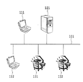
図1は、本発明を適用可能な印刷システムの全体構成の一例を示す図である。
(Overall configuration of printing system)
FIG. 1 is a diagram illustrating an example of the overall configuration of a printing system to which the present invention can be applied.
図1において、111および112はクライアントPC、121はプリントサーバ、131および132はコピー機能およびプリンタ機能を持つ印刷装置である。これらの装置はLAN101によって相互に接続されており、LAN101を介して互いに通信する。
In FIG. 1, 111 and 112 are client PCs, 121 is a print server, and 131 and 132 are printing apparatuses having a copy function and a printer function. These devices are connected to each other via a
クライアントPC111又は112は、ユーザによる指示を受け、印刷データを生成し、プリントサーバ121に送信する。
The client PC 111 or 112 receives an instruction from the user, generates print data, and transmits the print data to the
プリントサーバ121は、受信した印刷データを印刷装置131又は132に送信する。
The
印刷装置131又は132は、受信した印刷データを印刷画像に変換し、それを紙に印字する。印刷装置131又は132は、印刷データに対してN−up指定がされている場合に、印刷データのうちのNページ分を1枚のシートに印刷するためのデータを生成する。
The
上記の構成は一例であり、プリントサーバ121を含まない構成であってもよい。その場合、クライアントPC111又は112は、直接、印刷装置131又は132に印刷データを送信する。
The above configuration is an example, and a configuration not including the
(埋込情報の埋込印刷処理)
図2〜図5を参照して、N−up印刷時の埋込情報の埋込印刷処理を説明する。
(Embedding information embedding printing process)
With reference to FIGS. 2 to 5, the embedding information embedding printing process at the time of N-up printing will be described.
埋込情報の印刷処理においては、クライアントPCが印刷出力用の背景画像を生成する手法と、印刷装置が生成する手法とがある。図2及び図3を参照して前者の手法を説明し、図4及び図5を参照して後者の手法を説明する。なお、図2および図4は、クライアントPCおよび印刷装置の論理構成を示すブロック図であり、それらの装置の物理的構成を示すものではない。 In the embedded information printing process, there are a method in which the client PC generates a background image for print output and a method in which the printing apparatus generates. The former method will be described with reference to FIGS. 2 and 3, and the latter method will be described with reference to FIGS. 4 and 5. 2 and 4 are block diagrams showing the logical configuration of the client PC and the printing apparatus, and do not show the physical configuration of these apparatuses.
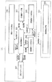
図2は、クライアントPCが印刷出力用の背景画像を生成する場合の構成例を示す図である。 FIG. 2 is a diagram illustrating a configuration example when the client PC generates a background image for print output.
図2において、111はクライアントPCであり、131は印刷装置である。
In FIG. 2,
まず、クライアントPC111の処理内容について説明する。 First, processing contents of the client PC 111 will be described.
ユーザがクライアントPC111を操作して印刷指示をおこなうと、印刷データ生成手段201が起動する。印刷データ生成手段201は、プリンタドライバとOSが協働する印刷サブシステムである。印刷データ生成手段201は、ユーザが印刷指示した電子ドキュメントから、印刷装置131に対する描画命令の集合(例えば、PDL(Page Description Language)である印刷データを生成する。
When the user operates the client PC 111 to give a print instruction, the print
なお、本実施例では、印刷データは、複数ページのデータから構成されているものとする。また、本実施例では、印刷データ内の各ページのデータが、電子ドキュメント内の各ページと1対1の対応関係になるように、印刷データ生成手段201は、印刷データを生成する。また、印刷データ生成手段201は、埋込情報も併せて生成する。本実施例では、以下に示すように、印刷データ生成手段201は、埋込情報を生成する。即ち、印刷データ生成手段201は、まず、印刷する電子ドキュメントの所在情報、印刷設定情報(N−up指定/解像度/拡縮等)、セキュリティ情報、検索情報等などの情報を抽出情報としてPDLから抽出する。本実施例では、この抽出情報は、印刷データを構成するページ数と同じだけ抽出されるため、複数のデータに分かれている。より正確に言うと、印刷データを構成する各ページと1対1の対応関係になるように、印刷データから抽出情報を抽出する。次いで、印刷データ生成手段201は、抽出情報に基づき埋込情報を生成する。なお、この埋込情報も抽出情報と同様に、印刷データを構成するページ数と同じだけのデータに分かれている。すなわち、各埋込情報は、印刷データ内の各ページに対応付けられている。
In this embodiment, it is assumed that the print data is composed of data of a plurality of pages. In this embodiment, the print
次いで、印刷データ生成手段201は、生成した印刷データ(複数ページのデータ)と埋込情報(この埋込情報は、複数のデータに分かれている)とを埋込情報制御手段202に出力する。
Next, the print
埋込情報制御手段202は、印刷データ生成手段201から印刷データと埋込情報を受け取る。次いで、埋込情報制御手段202は、埋込情報マージ手段203に埋込情報を出力し、さらに印刷データマージ手段207に印刷データと埋込情報とを出力する。
The embedded information control unit 202 receives print data and embedded information from the print
以降、本実施例では、埋込情報内の複数のデータの夫々のことを第1の埋込情報と称することにする。また、印刷データ内の複数のデータの夫々のことを第1の印刷データと称することにする。また、抽出情報内の複数のデータの夫々のことを第1の抽出情報と称することにする。 Hereinafter, in this embodiment, each of the plurality of data in the embedded information is referred to as first embedded information. Each of a plurality of data in the print data is referred to as first print data. Each of a plurality of data in the extraction information is referred to as first extraction information.
印刷データマージ手段207は、受け取った第1の埋込情報に含まれるN−up指定を解析し、各ページの印刷データ(第1の印刷データ)の統合処理を行うかどうかを判断する。具体的には、Nが2以上である場合には各ページの第1の印刷データの統合処理を行うと判断し、Nが1である場合には各ページの第1の印刷データの統合処理を行わないと判断する。
The print
埋込情報マージ手段203は、埋込情報内の複数のデータ(複数の第1の埋込情報)の統合処理を行う。統合処理とは、N−up指定がされていると解析された場合に、1枚のシートに印刷されるNページの夫々に対応付けられている埋込情報を統合することである。本実施例では、埋込情報マージ手段203は以下の処理を行う。 The embedded information merging means 203 performs integration processing of a plurality of data (a plurality of first embedded information) in the embedded information. The integration processing is integration of embedding information associated with each of N pages printed on one sheet when it is analyzed that N-up designation is performed. In the present embodiment, the embedded information merging means 203 performs the following processing.
埋込情報マージ手段203は、受け取った第1の埋込情報に含まれるN−up指定を解析し、各ページの第1の埋込情報の統合処理を行うかどうかを判断する。具体的には、Nが2以上である場合には各ページに対応する第1の埋込情報の統合処理を行うと判断し、Nが1である場合には各ページに対応する第1の埋込情報の統合処理を行わないと判断する。埋込情報マージ手段203は、統合処理を行うと判断した場合、各ページの第1の埋込情報を統合することにより第1の埋込情報を最適化する。本実施例では、第1の埋込情報を統合した結果を第2の埋込情報と称する。次いで、埋込情報マージ手段203は、第2の埋込情報を埋込情報制御手段202に出力する。これに対して、統合処理を行わない判断した場合、埋込情報マージ手段203は、第1の埋込情報を統合せずにそのまま埋込情報制御手段202に出力する。これらの処理の詳細については後ほど説明する。
The embedding
埋込情報制御手段202は、埋込情報マージ手段203から受け取った第2の埋込情報を背景画像データ生成手段204に出力する。
The embedding information control unit 202 outputs the second embedding information received from the embedding
背景画像データ生成手段204は、埋込情報制御手段202から受け取った第2の埋込情報を用いて背景画像データを生成する。具体的には、背景画像データ生成手段204は以下の処理を行う。 The background image data generation unit 204 generates background image data using the second embedded information received from the embedded information control unit 202. Specifically, the background image data generation unit 204 performs the following processing.
背景画像データ生成手段204は、埋込情報制御手段202から受け取った第2の埋込情報に基づいて背景画像データを生成する。背景画像データは、例えば、LVBC(Low Visibility Barcode)を用いて生成する。LVBCの詳細については後述する。次いで、背景画像データ生成手段204は、生成した背景画像データを埋込情報制御手段202に出力する。 The background image data generation unit 204 generates background image data based on the second embedding information received from the embedding information control unit 202. The background image data is generated using, for example, LVBC (Low Visibility Barcode). Details of the LVBC will be described later. Next, the background image data generation unit 204 outputs the generated background image data to the embedded information control unit 202.
背景画像データ合成手段205は、第1の印刷データの夫々と、第1の印刷データの夫々に対応する背景画像データを埋込情報制御手段202から受け取る。次いで、背景画像データ合成手段205は、受け取った第1の印刷データの夫々と、その夫々に対応する背景画像データを合成して合成印刷データを生成する。なお、背景画像データ合成手段205では、実際に合成しなくてもよく、第1の印刷データの夫々と、その夫々に対応する背景画像データとを印刷装置に合成させるためのデータを生成してもよい。そのような場合には、その生成してもよいデータが合成印刷データということになる。印刷データの各ページのデータ(第1の印刷データ)に背景画像データを入れる印刷命令を含む。背景画像データ合成手段205は、生成した合成印刷データを埋込情報制御手段202に出力する。
The background image
埋込情報制御手段202は、受け取った合成印刷データを印刷データ生成手段201に出力する。
The embedding information control unit 202 outputs the received composite print data to the print
印刷データ生成手段201は、埋込情報制御手段202から受け取った合成印刷データをプリントサーバ121(図示せず)、印刷装置131又は132に出力する。
The print
次に印刷装置131の処理内容について説明する。
Next, processing contents of the
印刷装置131は、印刷画像生成手段206を備える。印刷画像生成手段206は、データ受信部(図示せず)を備え、ネットワークインタフェースを制御することにより、LANからのデータを受信する。データ受信部は、クライアントPC111から又はLAN上の他のノードからのデータを受信すると、受信したデータを、そのデータの種別に応じて適切なサブシステムに出力する。例えば通信方式がTCP/IPである場合には、データ種別の識別は、一般的に、ポート番号によって行われる。本実施形態においては、受信したデータは、印刷装置131に対する印刷命令を含む合成印刷データである。
The
印刷画像生成手段206は、データ受信部が受信した合成印刷データの中から描画命令(PDL)を取り出し、それを解釈して、印刷装置131が内部的に使用する中間データを生成する。印刷装置131は、RIPを制御して、中間データを印刷画像に変換し、用紙に印字する。
The print
図3は、図2に示す構成での埋込印刷処理の流れを示すフローチャートである。 FIG. 3 is a flowchart showing the flow of the embedded printing process in the configuration shown in FIG.
S301において、印刷データ生成手段201は、第1の印刷データ、第1の埋込情報を生成し、生成した第1の印刷データと第1の埋込情報とを埋込情報制御手段202に出力する。次いで、埋込情報制御手段202は、埋込情報マージ手段203に埋込情報を出力し、さらに印刷データマージ手段207に第1の印刷データと第1の埋込情報とを出力する。
In step S <b> 301, the print
S302において、印刷データマージ手段207は、受け取った第1の埋込情報に含まれるN−up指定を解析し、各ページの第1の印刷データの統合処理を行うかどうかを判断する。具体的には、Nが2以上である場合には各ページの第1の印刷データの統合処理を行うと判断し、Nが1である場合には各ページの第1の印刷データの統合処理を行わないと判断する。
In step S302, the print
S303において、埋込情報マージ手段203は、複数の第1の埋込情報を統合処理することにより第1の埋込情報を最適化し、第2の埋込情報を生成する。埋込情報マージ手段203は、生成した第2の埋込情報を埋込情報制御手段202に出力する。次いで、埋込情報制御手段202は、第2の埋込情報を背景画像データ生成手段204に出力する。
In step S303, the embedding
S304において、背景画像データ生成手段204は、埋込情報制御手段202から受け取った第2の埋込情報を用いて背景画像データを生成し、生成した背景画像データを埋込情報制御手段202に出力する。 In step S <b> 304, the background image data generation unit 204 generates background image data using the second embedding information received from the embedding information control unit 202, and outputs the generated background image data to the embedding information control unit 202. To do.
S305において、背景画像データ合成手段205は、第1の印刷データの夫々と、第1の印刷データの夫々に対応する背景画像データを埋込情報制御手段202から受け取る。次いで、背景画像データ合成手段205は、受け取った第1の印刷データの夫々と、その夫々に対応する背景画像データを合成して合成印刷データを生成する。次いで、背景画像データ合成手段205は、生成した合成印刷データを埋込情報制御手段202に出力する。
In step S <b> 305, the background image
S306において、埋込情報制御手段202は、受け取った合成印刷データを、プリントサーバ121、印刷装置131又は132に出力する。
In step S <b> 306, the embedded information control unit 202 outputs the received composite print data to the
図4は、印刷装置が印刷出力用の背景画像を生成する場合の構成例を示す図である。 FIG. 4 is a diagram illustrating a configuration example when the printing apparatus generates a background image for print output.
図4において、111はクライアントPCであり、131は印刷装置である。
In FIG. 4,
まず、クライアントPC111の処理内容について説明する。
First, processing contents of the
ユーザがクライアントPC111を操作して印刷指示をおこなうと、印刷データ生成手段401が起動する。印刷データ生成手段401は、プリンタドライバとOSが協働する印刷サブシステムである。印刷データ生成手段401は、ユーザが印刷指示した電子ドキュメントから、印刷装置131に対する描画命令の集合(例えば、PDL)である第1の印刷データを生成する。このとき、印刷データ生成手段401は、第1の埋込情報も併せて生成する。例えば、印刷データ生成手段401は、印刷する電子ドキュメントの所在情報、印刷設定情報(N−up指定/解像度/拡縮等)、セキュリティ情報、検索情報等からなる埋込情報のパラメータをPDLから抽出する。次いで、印刷データ生成手段401は、抽出した埋込情報のパラメータに基づき第1の埋込情報を生成する。次いで、印刷データ生成手段401は、生成した第1の印刷データと第1の埋込情報を印刷装置131又は132、プリントサーバ121(図示せず)に出力する。
When the user operates the
次に印刷装置131の処理内容について説明する。
Next, processing contents of the
印刷画像生成手段402は、データ受信部(図示せず)を備え、ネットワークインタフェースを制御することにより、LANからのデータを受信する。データ受信部は、クライアントPC111から又はLAN上の他のノードからのデータを受信すると、受信したデータを、そのデータの種別によって適切なサブシステムに出力する。例えば通信方式がTCP/IPである場合には、データ種別の識別は、一般的に、ポート番号によって行われる。本実施形態においては、受信したデータには、印刷装置131に対する印刷命令を含む第1の印刷データ(PDL)と、第1の埋込情報が含まれる。印刷画像生成手段402は、データ受信部が受信したデータの中から、第1の埋込情報と第1の印刷データを取り出し、第1の印刷データを解釈して、印刷装置131が内部的に使用する中間データを生成する。そして、印刷装置131は、RIPを制御して、中間データを第1の印刷画像に変換する。
The print
印刷画像生成手段402は、第1の印刷画像と第1の埋込情報を埋込情報制御手段403に出力する。
The print
埋込情報制御手段403は、印刷画像生成手段402から第1の印刷画像と第1の埋込情報を受け取る。次いで、埋込情報制御手段403は、埋込情報マージ手段404に第1の埋込情報を出力し、さらに、印刷画像マージ手段407に第1の印刷画像と第1の埋込情報とを出力する。
The embedding information control unit 403 receives the first print image and the first embedding information from the print
印刷画像マージ手段407は、受け取った第1の埋込情報に含まれるN−up指定を解析し、各ページの印刷画像(第1の印刷画像)の統合処理を行うかどうかを判断する。具体的には、Nが2以上である場合には各ページの第1の印刷画像の統合処理を行うと判断し、Nが1である場合には各ページの第1の印刷画像の統合処理を行わないと判断する。
The print
埋込情報マージ手段404は、埋込情報内の複数のデータ(複数の第1の埋込情報)の統合処理を行う。具体的には、埋込情報マージ手段404は次の処理を行う。 The embedded information merging means 404 performs an integration process of a plurality of data (a plurality of first embedded information) in the embedded information. Specifically, the embedded information merging means 404 performs the following processing.
埋込情報マージ手段404は、受け取った第1の埋込情報に含まれるN−up指定を解析し、各ページの第1の埋込情報の統合処理を行うかどうかを判断する。具体的には、Nが2以上である場合には各ページに対応する第1の埋込情報の統合処理を行うと判断し、Nが1である場合には各ページに対応する第1の埋込情報の統合処理を行わないと判断する。埋込情報マージ手段404は、統合処理を行うと判断した場合、各ページの第1の埋込情報を統合することにより第1の埋込情報を最適化し、第2の埋め込み情報を生成する。次いで、埋込情報マージ手段404は、第2の埋込情報を埋込情報制御手段403に出力する。これに対して、統合処理を行わない判断した場合、埋込情報マージ手段404は、第1の埋込情報を統合せずにそのまま埋込情報制御手段403に出力する。これらの処理の詳細については後ほど説明する。
The embedding
埋込情報制御手段403は、埋込情報マージ手段404から受け取った第2の埋込情報を背景画像データ生成手段405に出力する。
The embedded information control unit 403 outputs the second embedded information received from the embedded
背景画像データ生成手段405は、埋込情報制御手段403から受け取った第2の埋込情報を用いて背景画像を生成する。具体的には、背景画像データ生成手段405は以下の処理を行う。 The background image data generation unit 405 generates a background image using the second embedded information received from the embedded information control unit 403. Specifically, the background image data generation unit 405 performs the following processing.
背景画像データ生成手段405は、埋込情報制御手段403から受け取った第2の埋込情報を用いて背景画像を生成する。背景画像は、例えば、LVBCを用いて生成する。LVBCの詳細については後述する。次いで、背景画像データ生成手段405は、生成した背景画像を埋込情報制御手段403に出力する。 The background image data generation unit 405 generates a background image using the second embedded information received from the embedded information control unit 403. The background image is generated using, for example, LVBC. Details of the LVBC will be described later. Next, the background image data generation unit 405 outputs the generated background image to the embedded information control unit 403.
背景画像データ合成手段406は、第1の印刷画像の夫々と、第1の印刷画像の夫々に対応する背景画像を埋込情報制御手段403から受け取る。次いで、背景画像データ合成手段406は、受け取った第1の印刷画像の夫々と、第1の印刷画像の夫々とに対応する背景画像を合成して合成印刷画像を生成する。なお、なお、背景画像データ合成手段406では、実際に合成しなくてもよく、第1の印刷画像の夫々と、その夫々に対応する背景画像とを印刷装置131に合成させるためのデータを生成してもよい。そのような場合には、その生成してもよいデータが合成印刷データということになる。背景画像データ合成手段405は、生成した合成印刷データを埋込情報制御手段403に出力する。
The background image
埋込情報制御手段403は、受け取った合成印刷画像を印刷画像生成手段402に出力する。
The embedding information control unit 403 outputs the received composite print image to the print
印刷画像生成手段402は、埋込情報制御手段403から受け取った合成印刷画像を用紙に印字する。
The print
図5は、図4に示す構成での埋込印刷処理の流れを示すフローチャートである。 FIG. 5 is a flowchart showing the flow of the embedded printing process in the configuration shown in FIG.
S501において、印刷データ生成手段401は、第1の印刷データ、第1の埋込情報を生成し、生成した第1の印刷データと第1の埋込情報とを印刷画像生成手段402に出力する。印刷画像生成手段402は、受信したデータの中から第1の埋込情報と第1の印刷データを取り出し、第1の印刷データを解釈して、印刷装置131が内部的に使用する中間データを生成し、その中間データを第1の印刷画像に変換する。印刷画像生成手段402は、第1の印刷画像と第1の埋込情報を埋込情報制御手段403に出力する。
In step S <b> 501, the print
埋込情報制御手段403は、印刷画像生成手段402から第1の印刷画像と第1の埋込情報を受け取る。次いで、埋込情報制御手段403は、埋込情報マージ手段404に第1の埋込情報を出力し、さらに、印刷画像マージ手段407に第1の印刷画像と第1の埋込情報とを出力する。
The embedding information control unit 403 receives the first print image and the first embedding information from the print
S502において、印刷画像マージ手段407は、受け取った第1の埋込情報に含まれるN−up指定を解析し、各ページの第1の印刷画像の統合処理を行うかどうかを判断する。具体的には、Nが2以上である場合には各ページの第1の印刷画像の統合処理を行うと判断し、Nが1である場合には各ページの第1の印刷画像の統合処理を行わないと判断する。
In step S <b> 502, the print
S503において、埋込情報マージ手段404は、受け取った第1の埋込情報に含まれるN−up指定を解析し、各ページの第1の埋込情報の統合処理を行うかどうかを判断する。具体的には、Nが2以上である場合には各ページに対応する第1の埋込情報の統合処理を行うと判断し、Nが1である場合には各ページに対応する第1の埋込情報の統合処理を行わないと判断する。埋込情報マージ手段404は、統合処理を行うと判断した場合、各ページの第1の埋込情報を統合することにより第1の埋込情報を最適化し、第2の埋め込み情報を生成する。次いで、埋込情報マージ手段404は、第2の埋込情報を背景画像データ生成手段405に出力する。
In step S503, the embedding
S504において、背景画像データ生成手段405は、埋込情報制御手段403から受け取った第2の埋込情報を用いて背景画像を生成し、生成した背景画像を埋込情報制御手段403に出力する。 In step S <b> 504, the background image data generation unit 405 generates a background image using the second embedded information received from the embedded information control unit 403, and outputs the generated background image to the embedded information control unit 403.
S505において、背景画像データ合成手段406は、第1の印刷画像の夫々と、第1の印刷画像の夫々に対応する背景画像を埋込情報制御手段403から受け取る。次いで、背景画像データ合成手段406は、受け取った第1の印刷画像の夫々と、その夫々に対応する背景画像を合成して合成印刷データを生成する。なお、背景画像データ合成手段406では、実際に合成しなくてもよく、第1の印刷画像の夫々と、その夫々に対応する背景画像とを印刷装置131に合成させるためのデータを生成してもよい。そのような場合には、その生成してもよいデータが合成印刷データということになる。次いで、背景画像データ合成手段406は、生成した合成印刷画像を埋込情報制御手段403に出力する。
In step S <b> 505, the background image
S506において、埋込情報制御手段403は、受け取った合成印刷画像を、プリントサーバ121、印刷装置131に出力する。
In step S <b> 506, the embedded information control unit 403 outputs the received composite print image to the
(埋込情報の統合処理)
図6及び図7を参照して、埋込情報マージ手段203、404による埋込情報の統合処理を説明する。
(Embedded information integration process)
With reference to FIGS. 6 and 7, the embedding information integration processing by the embedding information merging means 203 and 404 will be described.
図6は、埋込情報の具体的内容を示す図である。 FIG. 6 is a diagram showing specific contents of the embedded information.
601、611は、各ページの第1の埋込情報を示し、621は、統合処理された埋込情報、すなわち第2の埋込情報を示す。
前述した通り、第1の埋込情報は、印刷データ生成手段201、401が、PDLから抽出した情報に基づいて生成した情報である。本例は、PDLから抽出した第1の埋込情報のパラメータに基づいて第1の埋込情報を生成するが、他の方法を用いて第の埋込情報を生成してもよい。 As described above, the first embedding information is information generated by the print data generation means 201 and 401 based on information extracted from the PDL. In this example, the first embedding information is generated based on the parameters of the first embedding information extracted from the PDL, but the first embedding information may be generated using other methods.
602〜605、612〜615は、第1の埋込情報のパラメータである。本パラメータは、各ページに第1の埋込情報として埋め込まれる。631、632は、ヘッダ情報であり、本例ではページ番号を示す。
621は、601、611の各情報の共通項目を抜き出して、新たに生成した第2の埋込情報である。すなわち、621は、1ページ目の第1の埋込情報601と2ページ目の第1の埋込情報611とが統合された第2の埋込情報である。
第2の埋込情報621内の622〜626は、統合処理された第1の埋込情報の各パラメータである。622〜624は、各ページ共通のパラメータである。625、626は、各ページ固有のパラメータである。633、634、635は、ヘッダ情報である。633は、622〜624がページ共通のパラメータであることを示す。634、635は、ページ番号を示す。
図7は、第1の埋込情報を統合して第2の埋め込み情報を生成する処理(マージ処理)の流れを示すフローチャートである。 FIG. 7 is a flowchart showing a flow of processing (merging processing) for generating the second embedded information by integrating the first embedded information.
埋込情報マージ手段203、404は、N−up指定がされる各ページの第1の埋込情報の各パラメータの値を解析し、その解析結果に基づき、各ページ共通の第1の埋込情報を統合して、第2の埋込情報を生成する。 The embedding information merging means 203 and 404 analyze the value of each parameter of the first embedding information of each page for which N-up designation is performed, and based on the analysis result, the first embedding common to each page The information is integrated to generate second embedded information.
S701において、埋込情報マージ手段203、404は、統合処理を行っていない未処理項目のパラメータを取得する。ここで、埋込情報マージ手段203、404は、N−up指定され同一ページに印刷されるページのすべてのパラメータを取得する。
In step S <b> 701, the embedded
S702において、埋込情報マージ手段203、404は、Mページ((1≦M≦N)の未処理項目のパラメータの値が同一かどうかを判定する。項目とは、例えば、602、612の「ドキュメント情報(URL)」、603、613の「印刷制御情報」、604、614の「セキュリティ」、605、615の「検索情報」等である。埋込情報マージ手段203、404は、同じ項目ごとにパラメータの比較を行う。比較した結果、パラメータが異なる場合は、S703の処理に進み、パラメータが同じ場合は、S704の処理に進む。
In step S <b> 702, the embedded
S703において、埋込情報マージ手段203、404は、ページ毎の第2の埋込情報を生成する。具体的には、埋込情報マージ手段203、404は、605、615で示すページごとに異なるパラメータを、625、626に示すように、ページ固有の第2の埋込情報として統合する。
In step S <b> 703, the embedded
S704において、埋込情報マージ手段203、404は、ページ共通の第2の埋込情報を生成する。具体的には、埋込情報マージ手段203、404は、602と612、603と613、604と614のようにN−up処理する全ページに共通する第1の埋込情報を統合して第2の埋込情報を生成する。 In S704, the embedding information merging means 203, 404 generates second embedding information common to the pages. Specifically, the embedding information merging means 203 and 404 integrate the first embedding information common to all the pages to be N-up processed, such as 602 and 612, 603 and 613, and 604 and 614, to integrate the first embedding information. 2 embedded information is generated.
S705では、埋込情報マージ手段203,404は、第1の埋込情報に関して、すべての項目において統合が完了したかを判定する。S701〜S705の処理を繰り返すことによって、N−up処理されるすべてのページの項目に対して統合が行われ、第2の埋込情報が生成される。 In S705, the embedding information merging means 203, 404 determines whether integration has been completed for all items regarding the first embedding information. By repeating the processes of S701 to S705, the items of all pages to be N-up-processed are integrated, and the second embedded information is generated.
上述した通り、本実施形態では、複数の論理ページ毎に関連付けられた複数の第1の埋込情報を1つの物理ページ(一枚のシートに印刷するページ)上で1つに統合して、第2の埋込情報を生成する処理を行う。したがって、2−up処理の場合には、1つの物理ページ上に2つの論理ページに関する第1の埋込情報が統合されて第2の埋込情報として印刷される。 As described above, in the present embodiment, a plurality of first embedded information associated with each of a plurality of logical pages are integrated into one on one physical page (a page to be printed on one sheet), A process of generating the second embedded information is performed. Therefore, in the case of 2-up processing, the first embedding information related to two logical pages is integrated and printed as second embedding information on one physical page.
(埋込情報の抽出処理と抽出した埋込情報にしたがったコピー処理)
図8〜図11を参照して埋込情報の抽出処理と、抽出した埋込情報にしたがったコピー処理を説明する。
(Embedded information extraction processing and copy processing according to the extracted embedded information)
The embedding information extraction process and the copying process based on the extracted embedding information will be described with reference to FIGS.
図8は、埋込情報が埋め込まれた紙面のコピー処理を行う印刷装置131の構成例を示す図である。
FIG. 8 is a diagram illustrating a configuration example of the
図9は、図8に示す構成でのコピー処理の流れを示すフローチャートである。 FIG. 9 is a flowchart showing the flow of copy processing in the configuration shown in FIG.
S901において、コピー処理制御手段801は、操作部811からコピー処理の指示を受けると、スキャナ画像処理部812から印刷画像と埋込情報を取得する。印刷画像とは、背景画像を取り除いた画像である。スキャナ画像処理部812は、紙面から公知のスキャニングの技術と後述するLVBCの技術を用いて印刷画像と埋込情報を取得する。
In step S <b> 901, upon receiving a copy processing instruction from the
S902において、コピー処理制御手段801は、取得した印刷画像と埋込情報を印刷画像生成手段402に出力し、図4、図5を参照して説明したように埋込情報の埋込印刷処理を行う。
In step S902, the copy
印刷画像生成手段402、埋込情報制御手段403、埋込情報マージ手段404、背景画像データ生成手段405、背景画像データ合成手段406、印刷画像マージ手段407の構成・動作は、図4、図5を参照して説明した処理と同様であるので説明を省略する。
The configuration and operation of the print
図10は、埋込情報が埋め込まれた紙面の電子コピー処理を行う場合の構成例を示す図である。 FIG. 10 is a diagram illustrating a configuration example in the case of performing electronic copy processing of a paper surface in which embedded information is embedded.
図11は、図10に示す構成での電子コピー処理の流れを示すフローチャートである。 FIG. 11 is a flowchart showing the flow of electronic copy processing in the configuration shown in FIG.
S1101において、コピー処理制御手段1001は、操作部811から電子コピー処理の指示を受けると、スキャナ画像処理部812から埋込情報を取得する(S1101)。スキャナ画像処理部812は、紙面から公知のスキャニングの技術と後述するLVBCの技術を用いて埋込情報を抽出する。
In step S1101, upon receiving an instruction for electronic copy processing from the
S1102において、コピー処理制御手段1001は、抽出した埋込情報からドキュメント画像情報を取得し、ドキュメント画像情報取得手段1002に出力する。ドキュメント画像情報取得手段1002は、ドキュメント情報をコピー処理制御手段1001に出力する。ドキュメント情報とは、例えば、電子ドキュメントの所在を示すURLである。また、ドキュメント画像情報とは、例えば、アプリケーションの情報であるオープンフォーマットやビットマップである。
In step S1102, the copy
S1103において、コピー処理制御手段1001は、受け取ったドキュメント情報と埋込情報を印刷画像生成手段402に出力し、図4、図5を参照して説明したように埋込情報の埋込印刷処理を行う。
In step S1103, the copy
印刷画像生成手段402、埋込情報制御手段403、埋込情報マージ手段404、背景画像データ生成手段405、背景画像データ合成手段406、印刷画像マージ手段407の構成・動作は、図4、図5を参照して説明した処理と同様であるので説明を省略する。
The configuration and operation of the print
〈LVBCについて〉
次に、情報埋込技術の一例として、LVBC(Low Visibility Barcodes:低可視バーコード)を用いた技術を説明する。
<About LVBC>
Next, as an example of an information embedding technique, a technique using LVBC (Low Visibility Barcodes) will be described.
本実施形態においては、印刷装置は、原稿画像と共に所望の付加情報(以下、埋込情報という。)を用紙やOHPシート等のシートに印字する。 In the present embodiment, the printing apparatus prints desired additional information (hereinafter referred to as embedded information) together with a document image on a sheet such as paper or an OHP sheet.
情報埋込の要件は、一般的に、次の通りである。
・シートに十分な情報量の埋込情報を埋め込むことができる。
・シートに色材(トナーやインクなど)を使って埋め込まれた埋込情報を、後で、デジタル情報として確実に抽出できる。
・原稿画像をシートに複写する際に、埋込情報の抽出を妨げる要因(原稿の回転、拡大、縮小、部分的削除、複写による信号の鈍り、汚れ等)に対して耐性がある。
・複写禁止を示す埋込情報が埋め込まれている原稿の複写を防止するために、複写時にリアルタイム又はそれに準ずるスピードで埋込情報を抽出できる。
The requirements for information embedding are generally as follows.
-Embedding information with a sufficient amount of information can be embedded in the sheet.
-The embedded information embedded in the sheet using color materials (toner, ink, etc.) can be reliably extracted later as digital information.
When copying a document image on a sheet, it is resistant to factors that hinder the extraction of embedded information (rotation, enlargement, reduction, partial deletion, signal dullness due to copying, dirt, etc.).
In order to prevent copying of a document in which embedded information indicating copy prohibition is embedded, it is possible to extract embedded information at the time of copying or at a speed equivalent thereto.
図12は、LVBCが埋め込まれた原稿の一例を示す図である。 FIG. 12 is a diagram showing an example of a document in which LVBC is embedded.
1201はシート全体を示し、1202は1201の拡大図を示す。1202を参照すると、シートには、原稿に本来描画される画像の他に、多数のドット(1203)が印刷されている。LVBCを用いた情報埋込技術では、これらのドットを介して埋込情報をシートに埋め込む。
(埋込情報が埋め込まれる2つの領域)
次に、埋込情報が埋め込まれる領域について説明する。当該領域は、第1の領域と第2の領域に分けられる。
(Two areas where embedded information is embedded)
Next, the area where the embedded information is embedded will be described. The area is divided into a first area and a second area.
図13は、第1の領域と第2の領域に埋め込まれる埋込情報の特性を示す図である。 FIG. 13 is a diagram illustrating characteristics of embedded information embedded in the first region and the second region.
埋込情報は、特性の異なる2種類の埋込情報に分類される。各埋込情報は、個々に抽出可能なように第1の領域と第2の領域に別々に埋め込まれる。 Embedded information is classified into two types of embedded information having different characteristics. Each embedding information is separately embedded in the first area and the second area so that they can be extracted individually.
第1の領域には、印刷する電子ドキュメントの所在情報や、印刷パラメータの情報(N−up/解像度/拡縮等)、セキュリティ情報など、通常のスキャンによる複写操作時にリアルタイムで抽出しなければならない情報が埋め込まれる。第1の領域に埋め込まれた埋込情報の抽出処理は必ず実施されるために、埋込情報の抽出時の遅延は複写速度全体に影響を及ぼす。よって、埋込情報を解析する速度には、例えば、スキャン速度と同程度の速度が要求される。一方、これらの情報の情報量は少なくてよいため、そのデータサイズは小さくてすむ。 In the first area, information that must be extracted in real time during a copying operation by normal scanning, such as location information of an electronic document to be printed, information on printing parameters (N-up / resolution / enlargement / reduction, etc.), security information, and the like. Is embedded. Since the process of extracting the embedded information embedded in the first area is always performed, the delay in extracting the embedded information affects the entire copying speed. Accordingly, the speed for analyzing the embedded information is required to be approximately the same as the scan speed, for example. On the other hand, since the amount of these pieces of information may be small, the data size can be small.
第2の領域には、検索情報が埋め込まれる。検索情報は、例えば、ページ内のオブジェクトの座標情報やキーワードであり、オブジェクトの検索時に使用される。検索情報は、通常の複写時には使用されないため、検索情報の抽出は複写速度に影響を及ぼさない。検索情報の抽出は、必ずしもリアルタイムで行う必要がないため、検索情報の解析速度は、比較的低速でよい。したがって、検索情報には多量の情報を含ませることができる。 Search information is embedded in the second area. The search information is, for example, coordinate information or keywords of objects in the page, and is used when searching for objects. Since search information is not used during normal copying, extraction of search information does not affect the copying speed. Since the search information is not necessarily extracted in real time, the analysis speed of the search information may be relatively low. Therefore, a large amount of information can be included in the search information.
本実施形態のLVBCではこれらの特性が異なる埋込情報に対応するために、第1の領域と第2の領域とが混在した領域に埋込情報を埋め込む。そして、本実施形態では、埋込情報を、第1の領域のみから抽出、第2の領域のみから抽出又は両方の領域から抽出することを用途に応じて選択する。埋込情報を第1の領域のみから抽出する場合には、解析速度を向上させ、複写操作の生産性に影響を及ぼさない速度で抽出処理を行う。 In the LVBC of the present embodiment, the embedded information is embedded in a region where the first region and the second region are mixed in order to cope with embedded information having different characteristics. In the present embodiment, it is selected according to the use whether the embedded information is extracted from only the first region, extracted from only the second region, or extracted from both regions. When extracting the embedded information from only the first region, the analysis speed is improved, and the extraction process is performed at a speed that does not affect the productivity of the copying operation.
図14は、第1の領域と第2の領域の配置を説明するための図である。 FIG. 14 is a diagram for explaining the arrangement of the first region and the second region.
1401の四角の領域は第1の領域を示す。同じ四角の領域が周期的に複数並んでいるが、いずれの領域にも同じ埋込情報が格納される。このように、複数の第1の領域に同じ埋込情報を埋め込むことにより、埋込情報の冗長性が増し、その結果、ノイズや誤差に対する埋込情報の耐性が強化される。1403は第1の領域のサイズ、1404は第1の領域の繰り返し周期を示す。
A
1402の四角は第2の領域を示す。第2の領域も第1の領域と同様に、同じ四角の領域が周期的に複数並んでいる。特定の異なる上記2種類の埋込情報は、第1の領域1401と第2の領域とに排他的に埋め込まれる。1405は第2の領域のサイズを示す。
A square 1402 indicates the second region. Similarly to the first region, the second region has a plurality of the same square regions periodically arranged. The two different types of embedding information specified above are exclusively embedded in the
(LVBCの埋込方法)
次にLVBCの埋込方法について説明する。
(LVBC embedding method)
Next, a method for embedding LVBC will be described.
LVBCを用いた情報埋込方法においては、仮想的なグリッド(格子)が用いられる。 In the information embedding method using LVBC, a virtual grid is used.
埋込情報は、一定サイズ以内のバイナリデータである。埋込情報は、ドットをグリッドの交点から上下左右8方向のいずれかの方向に変位(交点からずらして配置)させることで、情報としてシートに埋め込まれる。 The embedded information is binary data within a certain size. The embedding information is embedded in the sheet as information by displacing the dots in one of the eight directions (up and down, left and right) from the grid intersection (displaced from the intersection).
図15は、グリッドと、ドットを配置する場所の位置関係を示す図である。 FIG. 15 is a diagram illustrating a positional relationship between a grid and a place where dots are arranged.
図15において、縦横の線1501は、グリッドを示す。1502は、グリッドの交点を示す。交点1502にはドットを配置しない。例えば、ドットは、交点1502から右下方向の離れた位置に配置される。
In FIG. 15, vertical and
図16は、埋込情報としてバイナリデータの010111110011を埋め込んだ例を示す図である。 FIG. 16 is a diagram illustrating an example in which binary data 010111110011 is embedded as embedded information.
バイナリデータの010111110011を埋め込むに際し、当該バイナリデータを010,111,110,011のように3ビット単位に分割する。次いで、各3ビット2進10進変換して、2,7,6,3の数値を得る。 When embedding binary data 010111110011, the binary data is divided into units of 3 bits such as 010, 111, 110, 011. Next, each 3-bit binary-decimal conversion is performed to obtain numerical values of 2, 7, 6, and 3.
埋込情報を表す数値に応じて、各ドットをグリッドの交点から上下左右の8方向のいずれかに変位させることによって、埋込情報を埋め込む。例えば、埋込情報として2,7,6,3を埋め込む場合、各ドットを右上、右下、下、左に変位させる。図16において、黒丸は、ドットを示す。LVBCを用いた情報埋込方法においては、上記の埋込を繰り返し行うことによって、2000バイト程度の情報量をもつ埋込情報をシートに埋め込むことができる。さらに、埋込情報を表現するこれらのドットをシートの全体にわたって埋め込むことによって、埋込情報の冗長性が増し、シートの汚れ、しわ、部分的破損に対する耐性が強化される。 The embedding information is embedded by displacing each dot in any of the eight directions up, down, left, and right from the intersection of the grids according to the numerical value representing the embedding information. For example, when embedding 2, 7, 6, 3 as embedding information, each dot is displaced to the upper right, lower right, lower and left. In FIG. 16, black circles indicate dots. In the information embedding method using LVBC, the embedded information having an information amount of about 2000 bytes can be embedded in the sheet by repeatedly performing the above-described embedding. Furthermore, by embedding these dots representing the embedding information throughout the sheet, the redundancy of the embedding information is increased and the resistance to dirt, wrinkles and partial breakage of the sheet is enhanced.
LVBCを解析するためには、まずグリッドの位置を正確に検出する必要がある。したがって、埋込情報を表すドットはグリッドの交点から8方向に等確率に出現することが望ましい。しかし、埋込情報として0等の特定の数値を多く埋め込む場合、埋込情報を表すドットは8方向の位置に等確率には出現しない可能性がある。そこで、LVBCを用いた情報埋込方法においては、埋込情報に対して可逆性を有したスクランブル処理(例えば共通鍵暗号処理)を施し、ドットの変位がランダムになるようにする。 In order to analyze the LVBC, it is first necessary to accurately detect the position of the grid. Therefore, it is desirable that the dots representing the embedding information appear with equal probability in eight directions from the grid intersection. However, when embedding many specific numerical values such as 0 as embedding information, there is a possibility that dots representing embedding information do not appear with equal probability at positions in eight directions. Therefore, in the information embedding method using LVBC, scramble processing (for example, common key encryption processing) having reversibility is performed on the embedded information so that the displacement of the dots becomes random.
LVBCを用いた情報埋込方法は、デジタルデータとしての埋込情報をアナログデータとしてシートに記録するDA変換ともいえるため、比較的単純な構成で実現可能である。 The information embedding method using LVBC can be said to be DA conversion in which embedding information as digital data is recorded on a sheet as analog data, and can therefore be realized with a relatively simple configuration.
(LVBCの解析方法)
次にLVBCの解析方法について説明する。
(LVBC analysis method)
Next, an LVBC analysis method will be described.
図17は、LVBCの解析を行う埋込情報解析部1701の構成を示すブロック図である。
FIG. 17 is a block diagram illustrating a configuration of an embedded
ドット検知部1702は、埋込情報が埋め込まれた画像(元画像と埋込情報とが混在した画像)から任意のドットを検知して、ドットの座標位置に変換する。
The
ドット解析部1703は、ドット検知部1702が検知したドットからハーフトーンを構成するドット等の不要なドットを排除する。
The
絶対座標リスト記憶部1704は、ドットの絶対座標位置のリストを格納する。
The absolute coordinate
ドット変換部1705は、絶対座標リスト記憶部1704が記憶する絶対座標位置のリストから回転角、グリッド間隔を検出し、絶対座標位置を、グリッドの位置からの相対座標位置に変換する。
The
相対座標リスト記憶部1706は、相対座標位置を記憶する。
The relative coordinate
第1領域復号部1707は、第1の領域に埋め込まれた埋込情報を抽出し、後段のモジュールに出力する。
The first
第2領域復号部1708は、第2の領域に埋め込まれた埋込情報を抽出し、後段のモジュールに出力する。
Second
後段のモジュールとは、埋込情報を利用する機能モジュールであり、例えば、埋込情報を再度、背景画像に変化させて合成画像を出力し、又は、ドキュメント情報を取得し、再印刷処理を行うモジュールである。 The post-stage module is a functional module that uses embedded information. For example, the embedded information is changed to a background image again to output a composite image, or document information is acquired and reprint processing is performed. It is a module.
(ドットの検知)
ドット検知部1702による処理を詳細に説明する。
(Dot detection)
Processing performed by the
ドット検知部1702は、光学スキャナが読み込んだ画像を多値モノクロイメージの形式で受信する。一方、LVBCを用いた情報埋込方法においては、埋込情報はモノクロ2値のドットで埋め込まれる。このため、情報埋込時のトナーの乗り具合、シートの取り扱い、スキャン時の光学系などの影響により、ドット検知部1702は、微細に信号が鈍った状態で信号を受信する。よって、ドット検知部1702は、これらの影響を排除するために、受信したドットの重心位置を座標位置と認識することにより検知精度を高めている。
The
図18は、ドット検知部1702によるドット検知を説明するための概念図である。
FIG. 18 is a conceptual diagram for explaining dot detection by the
ドット検知部1702は、画像上の孤立点を検査するために、画像に対して4方向からギャップの検査を実施する。1801〜1804は、孤立点の有無の検査を行なう方向を示す。例えば、縦方向1801のラインでの検査結果が、「白」、「白」、「黒」、「黒」、「白」、「白」である場合、黒の部分が孤立点である可能性がある。しかし、この検査だけでは、孤立点が横方向のライン上にある可能性もある。同様に、横方向1802のラインでの検査結果により、孤立点が横方向のライン上にある可能性があると判定した場合でも、実際には、孤立点が縦方向のライン上にある可能性もある。そこで、ドット検知部1702は、4つの方向1801〜1804において孤立点の検査を行なうことで検知精度を向上させる。ある領域において4つの方向1801〜1804のすべてにおいて上記の検査結果が得られたときに、黒の部分が孤立点であると識別する。
The
(ドットの解析)
ドット解析部1703による処理を詳細に説明する。
(Dot analysis)
Processing performed by the
ドット検知部1702が検知したドットがLVBCを構成するドット以外のドットである場合もある。例えば、原稿画像に含まれているハーフトーンを表現するためのドットパターンや、もともと原稿に含まれる孤立点(例えば平仮名の濁点など)等がそのようなドットに該当する。したがって、LVBCを構成するドットでは無い孤立点を削除するためにはハーフトーン除去を行う必要がある。
The dots detected by the
図19は、ハーフトーン除去を説明するためのグラフを示す図である。 FIG. 19 is a diagram illustrating a graph for explaining halftone removal.
グラフの縦軸はドットの粒形を示し、横軸は濃度を示す。また、グラフ内に、ドットの濃度として、ドットの頻度を表すヒストグラムを示す。ドットの濃度が濃い(より黒い)ほど、ドットの出現頻度が高いことを示す。LVBCの場合、ドットの粒形や濃度をそろえてドットを埋め込むため、ドットの出現頻度は、グラフ内の狭い位置でピークとなる(1901)。一方、ハーフトーンの場合、ドットの粒形や濃度が規格化されていないため、ドットは、グラフ内の広い位置にまばらに出現し、出現頻度も比較的低い。したがって、ドット解析部1703は、この特性を使用して、グラフ内の狭い位置で出現頻度がピークとなるドットをLVBCと判定して、それ以外のドットを排除する。したがって、絶対座標リスト記憶部1704は、LVBCのみを記憶することになる。
The vertical axis of the graph shows the particle shape of the dots, and the horizontal axis shows the density. In the graph, a histogram representing the dot frequency is shown as the dot density. The darker the dot density (the darker the color), the higher the frequency of dot appearance. In the case of LVBC, since the dots are embedded with the same particle shape and density, the frequency of dot appearance peaks at a narrow position in the graph (1901). On the other hand, in the case of halftone, since the particle shape and density of the dots are not standardized, the dots appear sparsely in a wide position in the graph, and the appearance frequency is relatively low. Therefore, the
(ドットの変換)
ドット変換部1705による処理を詳細に説明する。
(Dot conversion)
The processing by the
スキャナにシートを配置した向きの違いやアナログレベルでの微細なシートの角度のズレにより、スキャン時の画像の角度は、印刷時にLVBCドットを埋め込んだ画像の角度と異なる。したがって、画像の回転角の検知と、角度の補正を行う必要がある。また、LVBCの場合、グリッドを構成するドットを上下左右8方向に変位させることによって情報を埋め込むため、元のグリッドを再現する必要がある。したがって、元のグリッドの間隔を正確に特定する必要がある。 Due to the difference in the orientation of the sheet on the scanner and the deviation of the fine sheet angle at the analog level, the angle of the image at the time of scanning differs from the angle of the image in which the LVBC dots are embedded at the time of printing. Therefore, it is necessary to detect the rotation angle of the image and correct the angle. In the case of LVBC, since the information is embedded by displacing the dots constituting the grid in the eight directions, up, down, left, and right, it is necessary to reproduce the original grid. Therefore, it is necessary to specify the original grid interval accurately.
図20は、グリッドの間隔を測定する手法を説明した模式図である。 FIG. 20 is a schematic diagram illustrating a method of measuring the grid interval.
ドット2001に注目した場合、ドット2001からドット2001に最も近いドット2002までの距離Xがグリッドの間隔に近い。
When attention is paid to the
ドット2001に近いドットは上下左右に4箇所あるが、計算量を減らすため、ドット2001の右側の90度の範囲に存在するドットだけを、ドット2001に最も近いドットの候補とする。具体的には、注目するドット(x,y)と、それ以外の任意のドット(a,b)の関係が、
Although there are four dots close to the
![]()
![]()
である場合、ドット(a,b)を上記候補から外す。そして(x,y)と(a,b)間の距離が最小となる(a,b)を近隣ドットとし、2つのドット間の距離Xをグリッドの間隔の候補とする。 If so, the dot (a, b) is excluded from the candidates. Then, (a, b) that minimizes the distance between (x, y) and (a, b) is a neighboring dot, and a distance X between two dots is a candidate for a grid interval.
ここで、注目するドット2001も近隣ドット2002も変位している。また、LVBCとして認識されたドットは、実際は、ドット解析部1703が除去しそこねたハーフトーンパターンのドットかもしれない。そこですべての注目ドット(x,y)に対して上記のようにグリッド間の距離を計測して、すべての注目ドットに関してグリッド間の距離別の頻度を示したヒストグラムを作成する。
Here, the noticed
図21は、グリッド間の距離の頻度を示したヒストグラムの一例を示す図である。 FIG. 21 is a diagram illustrating an example of a histogram indicating the frequency of the distance between grids.
図21において、横軸はグリッド間距離の候補である距離の値、縦軸は注目ドット(x,y)において距離が計測された頻度を示す。図によれば、頻度が最も高い距離Xがグリッド間隔と識別される。すなわち、注目ドット2001と近隣ドット2002の出現確率が縦横ともに同じだとすると、多量の注目ドットのヒストグラムから、頻度が最も高い距離Xがグリッド間隔とすることができる。
In FIG. 21, the horizontal axis indicates the distance value that is a candidate for the distance between grids, and the vertical axis indicates the frequency at which the distance is measured at the target dot (x, y). According to the figure, the distance X having the highest frequency is identified as the grid interval. That is, if the appearance probability of the
図22は、グリッドの回転角度の補正を説明する図である。 FIG. 22 is a diagram illustrating correction of the rotation angle of the grid.
2201において、すべてのドットについて、それらのドットから近隣ドットの角度を測定する。 At 2201, the angle of neighboring dots is measured from all the dots.
本来、注目ドットからその近隣ドットの角度は0度、90度、180度、270度のいずれかであるため、測定した角度のズレを補正することにより回転角度を決定することが可能である。個々の注目ドットから近隣ドットの角度θは、注目ドットとその近隣ドットからなるベクトルを(dx,dy)とすると、下記の式であらわされる。 Originally, the angle of the neighboring dot to the neighboring dot is any one of 0 degree, 90 degree, 180 degree, and 270 degree. Therefore, the rotation angle can be determined by correcting the deviation of the measured angle. The angle θ between each dot of interest and the neighboring dot is expressed by the following equation, where (dx, dy) is a vector composed of the dot of interest and its neighboring dots.
![]()
![]()
2202は、A、B、C、Dのそれぞれの近隣点までのベクトルを示す。しかし実際には注目ドットも隣点ドットもグリッド位置からわずかに変位しているため、すべての注目ドットにおいてθを計測する。注目ドット2201と近隣ドットのそれぞれのグリッドからの変位位置の出現確率が縦横ともに同じだとすると、すべての注目ドットの角度のズレを加算することにより、平均的にグリッドの回転角度を計測することができる。2203はいくつかのドットのベクトルを表示したものであり、この角度を重ね合わせるとグリッドの回転角度に近似できることがわかる。
具体的には個々の注目ドットのθに対して再度、基準ベクトルを算出し、すべての基準ベクトルの合計結果から、トータルの角度φを求める。基準ベクトルの合計結果を(A,B)とすると、 Specifically, the reference vector is calculated again for θ of each target dot, and the total angle φ is obtained from the total result of all the reference vectors. If the total result of the reference vector is (A, B),

となり、グリッドの回転角度φは、 The rotation angle φ of the grid is
![]()
![]()
によって近似することが可能である。 It is possible to approximate by
絶対座標リスト記憶部1704に格納されている絶対座標リストに対して、グリッドの回転角度の逆回転を実施して、グリッドの角度を補正する。
The grid rotation angle is reversely rotated with respect to the absolute coordinate list stored in the absolute coordinate
回転角度の補正は90度単位には絞り込まれているが、実際には0度(正しい)、90度、180度、270度の4つまでは絞り込まれていない。この絞込みに関しては後述する。 The correction of the rotation angle is narrowed down to a unit of 90 degrees, but actually, it is not narrowed down to four of 0 degree (correct), 90 degrees, 180 degrees, and 270 degrees. This narrowing will be described later.
図23は、回転の補正結果およびグリッド位置を説明する図である。 FIG. 23 is a diagram for explaining a rotation correction result and a grid position.
図23において、2301は回転の補正が完了したLVBCドットの絶対座標リストを示す。さらに、2302で示すように、ドット変換部1705で求めたグリッド間隔毎に仮想的な直線をX方向、Y方向それぞれに引き、これら直線の交点をグリッドとする。このグリッドの位置からドットの座標の変位を計測する。
In FIG. 23,
(第1領域の特定)
図14で示した第1の領域のサイズ1403、繰り返し周期1404及び第1の領域の位置を特定する処理について説明する。
(Identification of the first area)
Processing for specifying the
最初に第1の領域1401の繰り返し周期1404の決定を行う。第1の領域1401には同じデータが周期的に入っており、縦方向に対して所定のオフセットで自己相関を取ると、オフセット値が繰り返し周期1404と一致したときに自己相関性が高まり、繰り返し周期1404を決定することができる。
First, the
図24はオフセット値に対応した自己相関値を計算した例を示すグラフである。 FIG. 24 is a graph showing an example in which an autocorrelation value corresponding to an offset value is calculated.
自己相関とは、特定の埋込データが周期的に出現する頻度を評価する手法であり、自己相関値とは特定のオフセット値における、埋込データの類似性を評価する数値である。 Autocorrelation is a technique for evaluating the frequency with which specific embedded data appears periodically, and the autocorrelation value is a numerical value for evaluating the similarity of embedded data at a specific offset value.
自己相関値を算出する自己相関関数COR(A,B)は下記の演算式で与えられる。 The autocorrelation function COR (A, B) for calculating the autocorrelation value is given by the following arithmetic expression.
COR(A,B) = bitcount(not (A xor B))
ここでxorは2項の排他的論理和を示しており、notは否定を示す。
COR (A, B) = bitcount (not (A xor B))
Here, xor indicates exclusive OR of two terms, and not indicates negation.
bitcountはビット列で1となるものの個数をカウントする関数である。 Bitcount is a function that counts the number of bits that become one.
例えば、Aが010b,Bが011bの場合はnot(A xor B)=not(001b)=110bとなり、bitcountは2となる。 For example, when A is 010b and B is 011b, not (A xor B) = not (001b) = 110b, and bitcount is 2.
ここで第1の領域があらかじめ決められた幅と高さを持つ行列とし、第1の領域を評価するためのビット列をCELL(x,y)とする。ここでx,yは縦、横の座標を示す。例えば第1の領域のサイズが幅=8、高さ=8だとすると、x,yを左上とした第1の領域は3bit x 8 x 8= 192bitがCELL(x,y)のビット列の長さとなる。 Here, the first area is a matrix having a predetermined width and height, and the bit string for evaluating the first area is CELL (x, y). Here, x and y indicate vertical and horizontal coordinates. For example, if the size of the first area is width = 8 and height = 8, the first area with x and y at the upper left is 3 bits x 8 x 8 = 192 bits is the length of the bit string of CELL (x, y) .
ここで、あるオフセットにおける、すべての座標の自己相関値は下記関数で表される。 Here, the autocorrelation values of all coordinates at a certain offset are expressed by the following function.
![]()
![]()
例えば第1の領域のサイズ1403を8,繰り返し周期1404を8x3=24としたときに自己相関を取るとオフセット=24で自己相関値はピーク2401となるため、オフセット=24を繰り返し周期1404と決定することが可能である。
For example, if the autocorrelation is taken when the
次に第1の領域1401の位置とサイズの決定を行う。自己相関を取ったことにより、第1の領域の繰り返し周期は決定したが、その中のどの位置に第1の領域があるかと第1の領域のサイズの決定が必要である。
Next, the position and size of the
図25は第1の領域の位置の決定方法を説明するための図である。 FIG. 25 is a diagram for explaining a method of determining the position of the first region.
あらかじめ第1の領域の繰り返し周期が決定しているので、相対座標リスト記憶部1706から任意の繰り返し周期分の領域を切り出す。ついで、その領域の隣の領域で相関を取り、さらに隣の領域で相関を取る、ということを繰り返す。この中で第1の領域2502の部分は繰り返し周期で同じデータが出現するので相関性が高い。それ以外の第2の領域2503は繰り返し周期では同じデータが出現しないので相関性が低い。この特性を利用して、相関性の高い部分の開始位置を第1の領域の開始位置と特定し、相関の高い部分の終わりまでのサイズを第1の領域のサイズと決定する。
Since the repetition period of the first area is determined in advance, an area corresponding to an arbitrary repetition period is cut out from the relative coordinate
(第1の領域の復号)
上記の処理で特定された第1の領域の位置とサイズから第1の領域のデータを復号する。
(Decoding of the first area)
The data of the first area is decoded from the position and size of the first area specified by the above processing.
単一の領域のデータだけを復号したのでは計測誤差やノイズが原因で誤判定する可能性があるため、すべての第1の領域に埋め込まれたドットの位置を集計し、最頻値を採用し、その値の生起確率を計算する。 Decoding only the data in a single area may cause misjudgment due to measurement errors and noise, so the positions of dots embedded in all the first areas are aggregated and the mode is adopted And the occurrence probability of the value is calculated.
図26は第1の領域に埋め込まれたドットの位置の集計を説明するための模式図である。 FIG. 26 is a schematic diagram for explaining the aggregation of the positions of dots embedded in the first area.
図26において、2601〜2603はシート上の異なる位置に存在する第1の領域である。これらを重ね合わせた結果が2604である。ノイズや誤差によるズレがあるが、すべての領域の集計結果によって最頻値が決まるため、この値を採用することができる。
In FIG. 26,
次に実際の復号を実施する。この段階においてノイズや計測誤差による影響が拭えないため、復号した結果にエラー訂正処理を施して復号を行う。 Next, actual decoding is performed. Since the influence of noise and measurement error cannot be wiped out at this stage, the decoding result is subjected to error correction processing for decoding.
まずは、図16に示したドットパターンから、ドットの位置を検出して、その位置に対応するデータに変換して、第1の領域に埋め込まれたデータ列を抽出する。このデータ列には実際に使用する複写禁止データの他に、データの破壊を検知、可能なら修復するエラー訂正符号が埋込時に記録されている。 First, a dot position is detected from the dot pattern shown in FIG. 16, converted into data corresponding to the position, and a data string embedded in the first area is extracted. In addition to the copy-inhibited data that is actually used, an error correction code that detects data corruption and repairs it if possible is recorded in this data string at the time of embedding.
エラー訂正符号には既知の技術として数多くされているが、ここではLDPC(Low Density Parity Check)方式を使用する。LDPCは誤り訂正能力が非常に高く、シャノン限界に近い特性を示すことで知られている。LDPCの詳細な説明に関しては省略する。また、LDPC以外であっても、エラー訂正符号の特性を持つ方式であればどのような方式であっても構わない。 Although many error correction codes are known as known techniques, an LDPC (Low Density Parity Check) method is used here. LDPC is known for its very high error correction capability and a characteristic close to the Shannon limit. A detailed description of LDPC will be omitted. Further, any system other than LDPC may be used as long as it has a characteristic of error correction code.
エラー訂正符号を用いることで、抽出したグリッドにある程度の誤差やノイズが含まれていても埋込データを抽出することが可能である。 By using an error correction code, it is possible to extract embedded data even if the extracted grid includes a certain amount of error or noise.
さらに、回転角度の補正で説明したとおり、回転角度の補正処理は90度単位で行うため、ここで抽出されたデータは正しいデータか、正しいデータを90度回転したものか、180度回転したものか、270度回転したものかの4通りが存在する。そこで、抽出データに対して、回転なし、90度回転、180度回転、270度回転した結果に対してそれぞれ見込みでLDPCによるエラー訂正を行った復号を実施する。正しい回転角度の場合にのみ、エラー訂正符号が機能し、正常にデータを抽出することが可能である。 Further, as described in the correction of the rotation angle, the correction process of the rotation angle is performed in units of 90 degrees, so that the data extracted here is correct data, whether the correct data is rotated 90 degrees, or rotated 180 degrees. There are four types, either 270 degrees or 270 degrees. Therefore, the extracted data is decoded by performing error correction by LDPC with respect to the results of no rotation, 90 ° rotation, 180 ° rotation, and 270 ° rotation, respectively. Only when the rotation angle is correct, the error correction code functions and data can be extracted normally.
図27は、回転を考慮し、エラー訂正を行った復号の処理を説明するための図である。 FIG. 27 is a diagram for explaining a decoding process in which error correction is performed in consideration of rotation.
図27において、この例では正しいデータに対して270度回転した結果が抽出されたとする。2701において最初に抽出データに対してそのままエラー訂正処理を実施する。正しいデータはエラー訂正符号を含んでいるが、回転することによって意味のないデータになってしまうため、エラー訂正することができない。次に2702において、2701に対して90度回転を施したデータに対してエラー訂正処理を実施する。同様にエラー訂正に失敗するため、データを抽出することができない。次に2703において、2702に対して90度回転を施したデータに対してエラー訂正処理を実施する。同様にエラー訂正に失敗するため、データを抽出することができない。最後に2704において、2703に対して90度回転を施したデータに対してエラー訂正処理を実施する。これは正しいデータであるため、エラー訂正処理に成功するため、抽出データとして採用することが可能である。 In FIG. 27, in this example, it is assumed that a result of 270 degrees rotation with respect to correct data is extracted. In 2701, error correction processing is performed on the extracted data as it is. The correct data includes an error correction code, but it becomes meaningless data by rotating, and thus error correction cannot be performed. Next, in 2702, error correction processing is performed on the data obtained by rotating 90 ° with respect to 2701. Similarly, since error correction fails, data cannot be extracted. Next, in 2703, error correction processing is performed on the data that has been rotated 90 degrees with respect to 2702. Similarly, since error correction fails, data cannot be extracted. Finally, in 2704, error correction processing is performed on the data that has been rotated 90 degrees with respect to 2703. Since this is correct data, it can be adopted as extracted data because error correction processing is successful.
2704でもエラー訂正処理に失敗した場合、誤差やノイズが多くてデータの抽出に失敗したことが考えられる。 Even if 2704 fails in error correction processing, it is considered that data extraction has failed due to many errors and noise.
以上の処理によって第1の領域に格納された埋込データを抽出できる。 The embedded data stored in the first area can be extracted by the above processing.
(第2の領域の特定)
第2の領域は追跡情報などの登録に使う領域であり、複写操作実施時には必ずしも必要な情報ではない。よって不要な場合は第2の領域の復号を省くことにより、全体の処理の速度低下を抑えることが可能である。
(Identification of second area)
The second area is an area used for registering tracking information and the like, and is not necessarily necessary information when performing a copying operation. Therefore, when it is unnecessary, it is possible to suppress a decrease in the overall processing speed by omitting the decoding of the second area.
以下に第2領域の特定方法について説明する。 A method for specifying the second region will be described below.
最初に第1の領域と同様、第2の領域の自己相関を取る。第2の領域は第1の領域の繰返し同期の倍数で埋め込まれるため、第1の領域の繰り返し回数の倍数(例の場合、24,48,72,….)単位のいずれかで自己相関をとればよいので計算を省くことが可能である。さらに第2の領域は繰り返し同期=第2の領域のサイズとなる。 First, as in the first region, the autocorrelation of the second region is taken. Since the second area is embedded with a multiple of the first area's repetitive synchronization, autocorrelation is performed in one of multiples of the first area's repetition count (24, 48, 72,... In the example). Therefore, the calculation can be omitted. Further, the second area has repeated synchronization = the size of the second area.
図28は、第2の領域におけるオフセット値に対応した自己相関値を計算した例を示すグラフである。 FIG. 28 is a graph illustrating an example in which an autocorrelation value corresponding to the offset value in the second region is calculated.
最後に第2の領域の開始位置の特定を行う。埋込むときに第1の領域の開始位置と第2の領域の開始位置を同期させるため、位置は第1の領域の開始位置のいずれかに絞り込むことが可能である。 Finally, the start position of the second area is specified. Since the start position of the first area and the start position of the second area are synchronized when embedding, the position can be narrowed down to one of the start positions of the first area.
第2の領域の位置決定にはエラー訂正符号を利用する。第1の領域と同様に第2の領域に関しても埋込データの他にエラー訂正符号が付加される。第2の領域のサイズはわかっているため、第1の領域の先頭位置から順番に見込みでエラー訂正処理を実施していく。 An error correction code is used to determine the position of the second region. Similar to the first region, an error correction code is added to the second region in addition to the embedded data. Since the size of the second area is known, the error correction process is executed in order starting from the first position of the first area.
図29は第2の領域の位置を特定する方法を説明するための図である。 FIG. 29 is a diagram for explaining a method of specifying the position of the second region.
図29において、自己相関によって第2の領域のサイズが第1の領域の繰り返し同期の4倍であることを示している。ここで4x4=16のいずれかが第2領域の開始位置となるため、1、2、3、4、5、と位置をずらしながら、エラー訂正処理を適用する。エラー訂正処理に成功した場合、その位置を第2領域として採用することが可能である。 In FIG. 29, the autocorrelation indicates that the size of the second area is four times the repeated synchronization of the first area. Here, since any of 4 × 4 = 16 is the start position of the second region, the error correction process is applied while shifting the position from 1, 2, 3, 4, 5, and so on. When the error correction process is successful, the position can be adopted as the second area.
以上によって第2の領域に格納された埋込データの抽出が実施可能である。 As described above, the embedded data stored in the second area can be extracted.
〈その他の実施例〉
前述した実施形態の機能を実現するプログラムを記録媒体に記憶させ、該記録媒体に記憶されたプログラムをコードとして読み出し、コンピュータにおいて実行する処理方法も上述の実施形態の範疇に含まれる。また、前述のプログラムが記憶されたコンピュータ読み取り可能な記録媒体はもちろんそのプログラム自体も上述の実施形態に含まれる。かかる記録媒体としては、例えばフロッピー(登録商標)ディスク、ハードディスク、光ディスク、光磁気ディスク、CD―ROM、磁気テープ、不揮発性メモリカード、ROMがある。また前述の記録媒体に記憶されたプログラム単体で処理を実行しているものに限らず、他のソフトウエア、拡張ボードの機能と共同して、OS上で動作し前述の実施形態の動作を実行するものも前述した実施形態の範疇に含まれる。
<Other Examples>
A processing method for storing a program for realizing the functions of the above-described embodiment in a recording medium, reading the program stored in the recording medium as a code, and executing the program on a computer is also included in the category of the above-described embodiment. In addition to the computer-readable recording medium storing the above-described program, the program itself is included in the above-described embodiment. Examples of such a recording medium include a floppy (registered trademark) disk, a hard disk, an optical disk, a magneto-optical disk, a CD-ROM, a magnetic tape, a nonvolatile memory card, and a ROM. In addition, the processing is not limited to the single program stored in the recording medium described above, but operates on the OS in cooperation with other software and the function of the expansion board to execute the operation of the above-described embodiment. This is also included in the category of the embodiment described above.
その他、プログラムの供給方法としては、クライアントコンピュータのブラウザを用いてインターネットのホームページからプログラム又は圧縮され自動インストール機能を含むファイルをハードディスク等の記録媒体にダウンロードする方法がある。また、本発明のプログラムを構成するプログラムコードを複数のファイルに分割し、それぞれのファイルを異なるホームページからダウンロードすることによっても実現可能である。つまり、本発明の機能処理をコンピュータで実現するためのプログラムファイルを複数のユーザに対してダウンロードさせるWWWサーバも、本発明に含まれるものである。 As another program supply method, there is a method of downloading a program or a compressed file including an automatic installation function from a homepage on the Internet to a recording medium such as a hard disk using a browser of a client computer. It can also be realized by dividing the program code constituting the program of the present invention into a plurality of files and downloading each file from a different homepage. That is, a WWW server that allows a plurality of users to download a program file for realizing the functional processing of the present invention on a computer is also included in the present invention.
また、前述のプログラムを暗号化してCD−ROM等の記録媒体に格納してユーザに配布し、所定の条件をクリアしたユーザに対し暗号化を解く鍵情報をインターネットからダウンロードさせる。次いで、その鍵情報を用いて暗号化されたプログラムを実行してコンピュータにインストールさせることもできる。 In addition, the above-described program is encrypted, stored in a recording medium such as a CD-ROM, distributed to the user, and the user who clears the predetermined condition is allowed to download key information for decryption from the Internet. Next, the program encrypted using the key information can be executed and installed in the computer.
111、112 クライアントPC
121 プリントサーバ
131,132 印刷装置
201 印刷データ生成手段
202 埋込情報制御手段
203 埋込情報マージ手段
204 背景画像データ生成手段
205 背景画像データ合成手段
206 印刷画像生成手段
401 印刷データ生成手段
402 印刷画像生成手段
403 埋込情報制御手段
404 埋込情報マージ手段
405 背景画像データ生成手段
406 背景画像データ合成手段
111, 112 Client PC
121
Claims (4)
前記印刷データ内の各ページに対応付けられている、N−up指定を含む各埋込情報を取得する手段と、
取得した前記各埋込情報を解析し、前記N−up指定においてNが2以上であるかどうかを判定する手段と、
前記N−up指定においてNが2以上であると判定された場合、前記1枚のシートに印刷されるNページの夫々に対応付けられている埋込情報を統合する手段と、
前記シートの印刷領域の全面に周期的に並んだ複数の第2領域と当該第2の領域内に周期的に並んだ複数の第1の領域とによって構成され、当該第1及び第2の領域のそれぞれにおいて仮想的な格子の交点からずれて配置されたドットの位置によって情報が符号化される符号画像であって、前記第1の領域に埋め込まれる情報は複写時にリアルタイムで抽出しなければならない情報であり、前記第2の領域に埋め込まれる情報は複写時にリアルタイムで抽出しなくてもよい情報であり、前記第1の領域に埋め込まれる情報量は前記第2の領域に埋め込まれる情報量よりも少ない、符号画像を、前記統合された埋込情報を用いて生成する手段と、
前記Nページ分を1枚のシートに印刷するためのデータに、生成した前記符号画像を合成する手段と
を備えることを特徴とする印刷装置。 In a printing apparatus that generates data for printing N pages of print data on one sheet,
Means for acquiring each embedded information including N-up designation associated with each page in the print data;
Means for analyzing each acquired embedded information and determining whether N is 2 or more in the N-up designation;
Means for integrating embedding information associated with each of N pages printed on the one sheet when N is determined to be 2 or more in the N-up designation;
The first and second regions are configured by a plurality of second regions periodically arranged on the entire print region of the sheet and a plurality of first regions periodically arranged in the second region. Each of which is a code image in which information is encoded by the positions of dots arranged offset from the intersections of virtual grids, and the information embedded in the first area must be extracted in real time during copying The information embedded in the second area is information that does not need to be extracted in real time during copying, and the amount of information embedded in the first area is greater than the amount of information embedded in the second area. Means for generating a code image using the integrated embedded information,
A printing apparatus comprising: means for combining the generated code image with data for printing the N pages for one sheet.
前記印刷データ内の各ページに対応付けられている、N−up指定を含む各埋込情報を取得するステップと、
取得した前記各埋込情報を解析し、前記N−up指定においてNが2以上であるかどうかを判定するステップと、
前記N−up指定においてNが2以上であると判定された場合、前記1枚のシートに印刷されるNページの夫々に対応付けられている埋込情報を統合するステップと、
前記シートの印刷領域の全面に周期的に並んだ複数の第2領域と当該第2の領域内に周期的に並んだ複数の第1の領域とによって構成され、当該第1及び第2の領域のそれぞれにおいて仮想的な格子の交点からずれて配置されたドットの位置によって情報が符号化される符号画像であって、前記第1の領域に埋め込まれる情報は複写時にリアルタイムで抽出しなければならない情報であり、前記第2の領域に埋め込まれる情報は複写時にリアルタイムで抽出しなくてもよい情報であり、前記第1の領域に埋め込まれる情報量は前記第2の領域に埋め込まれる情報量よりも少ない、符号画像を、前記統合された埋込情報を用いて生成するステップと、
前記Nページ分を1枚のシートに印刷するためのデータに、生成した前記符号画像を合成するステップと
を含むことを特徴とする印刷方法。 In a printing method for generating data for printing N pages of print data on one sheet,
Obtaining each embedding information including N-up designation associated with each page in the print data;
Analyzing each acquired embedding information and determining whether N is 2 or more in the N-up designation;
A step of integrating embedding information associated with each of N pages printed on the one sheet when N is determined to be 2 or more in the N-up designation;
The first and second regions are configured by a plurality of second regions periodically arranged on the entire print region of the sheet and a plurality of first regions periodically arranged in the second region. Each of which is a code image in which information is encoded by the positions of dots arranged offset from the intersections of virtual grids, and the information embedded in the first area must be extracted in real time during copying The information embedded in the second area is information that does not need to be extracted in real time during copying, and the amount of information embedded in the first area is greater than the amount of information embedded in the second area. Generating a code image using the integrated embedding information,
Synthesizing the generated code image with data for printing the N pages for one sheet.
Priority Applications (2)
| Application Number | Priority Date | Filing Date | Title |
|---|---|---|---|
| JP2007160339A JP4871794B2 (en) | 2007-06-18 | 2007-06-18 | Printing apparatus and printing method |
| US12/137,289 US8351086B2 (en) | 2007-06-18 | 2008-06-11 | Two-dimensional code generating device |
Applications Claiming Priority (1)
| Application Number | Priority Date | Filing Date | Title |
|---|---|---|---|
| JP2007160339A JP4871794B2 (en) | 2007-06-18 | 2007-06-18 | Printing apparatus and printing method |
Publications (3)
| Publication Number | Publication Date |
|---|---|
| JP2008312139A JP2008312139A (en) | 2008-12-25 |
| JP2008312139A5 JP2008312139A5 (en) | 2010-07-01 |
| JP4871794B2 true JP4871794B2 (en) | 2012-02-08 |
Family
ID=40132019
Family Applications (1)
| Application Number | Title | Priority Date | Filing Date |
|---|---|---|---|
| JP2007160339A Expired - Fee Related JP4871794B2 (en) | 2007-06-18 | 2007-06-18 | Printing apparatus and printing method |
Country Status (2)
| Country | Link |
|---|---|
| US (1) | US8351086B2 (en) |
| JP (1) | JP4871794B2 (en) |
Families Citing this family (7)
| Publication number | Priority date | Publication date | Assignee | Title |
|---|---|---|---|---|
| US7831244B2 (en) * | 1999-06-30 | 2010-11-09 | Silverbrook Research Pty Ltd | Retrieving an image via a coded surface |
| JP4666026B2 (en) * | 2008-08-12 | 2011-04-06 | コニカミノルタビジネステクノロジーズ株式会社 | Image forming apparatus and image forming method |
| JP4875132B2 (en) * | 2009-10-29 | 2012-02-15 | シャープ株式会社 | Image processing apparatus, image data output processing apparatus, and image processing method |
| JP5371797B2 (en) * | 2010-01-12 | 2013-12-18 | キヤノン株式会社 | Device, method and program capable of handling codes |
| JP6029344B2 (en) * | 2012-06-20 | 2016-11-24 | キヤノン株式会社 | Image processing apparatus, image processing method, and program |
| CN103001948B (en) * | 2012-11-09 | 2015-06-17 | 北京奇艺世纪科技有限公司 | Method and system for controlling computer terminal by handheld device through scan codes |
| CN111178109A (en) * | 2019-11-28 | 2020-05-19 | 北京爱创科技股份有限公司 | Device and method for detecting packaging association relation and packaging box |
Family Cites Families (10)
| Publication number | Priority date | Publication date | Assignee | Title |
|---|---|---|---|---|
| JPH0644320A (en) * | 1991-05-14 | 1994-02-18 | Sony Corp | Information retrieval system |
| JP2967341B2 (en) * | 1997-06-12 | 1999-10-25 | 富士ゼロックス株式会社 | Embedding code generation method and apparatus |
| US6067554A (en) * | 1997-09-11 | 2000-05-23 | International Business Machines Corp. | Method and apparatus for displaying print documents |
| JP3363793B2 (en) * | 1998-07-10 | 2003-01-08 | キヤノン株式会社 | Print control method and apparatus |
| JP3511502B2 (en) * | 2000-09-05 | 2004-03-29 | インターナショナル・ビジネス・マシーンズ・コーポレーション | Data processing detection system, additional information embedding device, additional information detection device, digital content, music content processing device, additional data embedding method, content processing detection method, storage medium, and program transmission device |
| JP2004128664A (en) * | 2002-09-30 | 2004-04-22 | Canon Inc | Image processor and processing method |
| JP3959011B2 (en) * | 2002-10-15 | 2007-08-15 | 株式会社リコー | Print management system |
| US7099037B2 (en) * | 2003-04-22 | 2006-08-29 | Lightning Source Inc. | N-up printing |
| GB2404271B (en) * | 2003-07-24 | 2006-06-21 | Hewlett Packard Development Co | Print having attached data storage, storage medium therefore and method of providing same |
| JP4687279B2 (en) * | 2005-06-29 | 2011-05-25 | ソニー株式会社 | Image reproduction apparatus, image reproduction method, and image reproduction program |
-
2007
- 2007-06-18 JP JP2007160339A patent/JP4871794B2/en not_active Expired - Fee Related
-
2008
- 2008-06-11 US US12/137,289 patent/US8351086B2/en not_active Expired - Fee Related
Also Published As
| Publication number | Publication date |
|---|---|
| US8351086B2 (en) | 2013-01-08 |
| JP2008312139A (en) | 2008-12-25 |
| US20080309981A1 (en) | 2008-12-18 |
Similar Documents
| Publication | Publication Date | Title |
|---|---|---|
| JP4343968B2 (en) | Image forming apparatus and method | |
| JP4557765B2 (en) | Image processing apparatus and method | |
| JP4854491B2 (en) | Image processing apparatus and control method thereof | |
| JP4871794B2 (en) | Printing apparatus and printing method | |
| US20090021793A1 (en) | Image processing device, image processing method, program for executing image processing method, and storage medium for storing program | |
| US8073188B2 (en) | Image generation apparatus, computer readable medium, computer data signal, information generation method, information reading system, electronic pen and recording medium | |
| US7481374B2 (en) | System and method for placement and retrieval of embedded information within a document | |
| JP4552754B2 (en) | Information embedding device, method, program, and recording medium, and information detecting device, method, program, and computer-readable recording medium | |
| JP4380733B2 (en) | Apparatus and method for managing copy history of manuscript | |
| US20070064036A1 (en) | Information processing apparatus, association method | |
| CN101388111A (en) | Image processing device and method | |
| Tan et al. | Print-Scan Resilient Text Image Watermarking Based on Stroke Direction Modulation for Chinese Document Authentication. | |
| JP4673200B2 (en) | Print processing system and print processing method | |
| JP4440283B2 (en) | Image processing apparatus, control method thereof, control program, and storage medium | |
| JP5159345B2 (en) | Device, method, and program for handling embedded code | |
| JP4838778B2 (en) | Additional information expression device and additional information expression method | |
| JP2009060230A (en) | Image forming apparatus and its control method and program, and storage medium | |
| JP2008028716A (en) | Image processing method and apparatus | |
| CN100501728C (en) | Image processing method, system, program, program storage medium and information processing apparatus | |
| JP2008085579A (en) | Device for embedding information, information reader, method for embedding information, method for reading information and computer program | |
| US8125691B2 (en) | Information processing apparatus and method, computer program and computer-readable recording medium for embedding watermark information | |
| JP4552757B2 (en) | Image processing apparatus, image processing method, and image processing program | |
| JP2008186256A (en) | Document processor, document processing method, and computer program | |
| JP4517667B2 (en) | Document image collation device, document image alignment method and program | |
| JP4587492B2 (en) | Image forming apparatus and method |
Legal Events
| Date | Code | Title | Description |
|---|---|---|---|
| A621 | Written request for application examination |
Free format text: JAPANESE INTERMEDIATE CODE: A621 Effective date: 20100330 |
|
| A521 | Written amendment |
Free format text: JAPANESE INTERMEDIATE CODE: A523 Effective date: 20100518 |
|
| RD02 | Notification of acceptance of power of attorney |
Free format text: JAPANESE INTERMEDIATE CODE: A7422 Effective date: 20101106 |
|
| A977 | Report on retrieval |
Free format text: JAPANESE INTERMEDIATE CODE: A971007 Effective date: 20110707 |
|
| A131 | Notification of reasons for refusal |
Free format text: JAPANESE INTERMEDIATE CODE: A131 Effective date: 20110715 |
|
| A521 | Written amendment |
Free format text: JAPANESE INTERMEDIATE CODE: A523 Effective date: 20110824 |
|
| A131 | Notification of reasons for refusal |
Free format text: JAPANESE INTERMEDIATE CODE: A131 Effective date: 20110909 |
|
| A521 | Written amendment |
Free format text: JAPANESE INTERMEDIATE CODE: A523 Effective date: 20110927 |
|
| TRDD | Decision of grant or rejection written | ||
| A01 | Written decision to grant a patent or to grant a registration (utility model) |
Free format text: JAPANESE INTERMEDIATE CODE: A01 Effective date: 20111021 |
|
| A01 | Written decision to grant a patent or to grant a registration (utility model) |
Free format text: JAPANESE INTERMEDIATE CODE: A01 |
|
| A61 | First payment of annual fees (during grant procedure) |
Free format text: JAPANESE INTERMEDIATE CODE: A61 Effective date: 20111121 |
|
| FPAY | Renewal fee payment (event date is renewal date of database) |
Free format text: PAYMENT UNTIL: 20141125 Year of fee payment: 3 |
|
| LAPS | Cancellation because of no payment of annual fees |