JP4871268B2 - Access and closure devices and methods - Google Patents
Access and closure devices and methods Download PDFInfo
- Publication number
- JP4871268B2 JP4871268B2 JP2007513356A JP2007513356A JP4871268B2 JP 4871268 B2 JP4871268 B2 JP 4871268B2 JP 2007513356 A JP2007513356 A JP 2007513356A JP 2007513356 A JP2007513356 A JP 2007513356A JP 4871268 B2 JP4871268 B2 JP 4871268B2
- Authority
- JP
- Japan
- Prior art keywords
- lumen
- arteriotomy
- introducer
- anchor
- toggle
- Prior art date
- Legal status (The legal status is an assumption and is not a legal conclusion. Google has not performed a legal analysis and makes no representation as to the accuracy of the status listed.)
- Expired - Fee Related
Links
- 238000000034 method Methods 0.000 title description 81
- 210000004204 blood vessel Anatomy 0.000 claims description 18
- 210000001367 artery Anatomy 0.000 claims 1
- 230000003796 beauty Effects 0.000 claims 1
- 239000000463 material Substances 0.000 description 17
- 230000002792 vascular Effects 0.000 description 9
- 238000000576 coating method Methods 0.000 description 8
- 230000023597 hemostasis Effects 0.000 description 7
- 239000011248 coating agent Substances 0.000 description 6
- -1 polypropylene Polymers 0.000 description 6
- 102000008186 Collagen Human genes 0.000 description 5
- 108010035532 Collagen Proteins 0.000 description 5
- 229920001436 collagen Polymers 0.000 description 5
- 239000011159 matrix material Substances 0.000 description 5
- 229920000642 polymer Polymers 0.000 description 5
- 229920001343 polytetrafluoroethylene Polymers 0.000 description 5
- 239000004810 polytetrafluoroethylene Substances 0.000 description 5
- QTBSBXVTEAMEQO-UHFFFAOYSA-N Acetic acid Chemical compound CC(O)=O QTBSBXVTEAMEQO-UHFFFAOYSA-N 0.000 description 4
- 208000007536 Thrombosis Diseases 0.000 description 4
- 230000000740 bleeding effect Effects 0.000 description 4
- 230000014759 maintenance of location Effects 0.000 description 4
- 229910001000 nickel titanium Inorganic materials 0.000 description 4
- 210000001519 tissue Anatomy 0.000 description 4
- 229920004934 Dacron® Polymers 0.000 description 3
- 239000004677 Nylon Substances 0.000 description 3
- 239000004743 Polypropylene Substances 0.000 description 3
- 239000004098 Tetracycline Substances 0.000 description 3
- 229910045601 alloy Inorganic materials 0.000 description 3
- 239000000956 alloy Substances 0.000 description 3
- 230000017531 blood circulation Effects 0.000 description 3
- 230000006835 compression Effects 0.000 description 3
- 238000007906 compression Methods 0.000 description 3
- 230000006837 decompression Effects 0.000 description 3
- 239000004744 fabric Substances 0.000 description 3
- 229920001778 nylon Polymers 0.000 description 3
- 230000037361 pathway Effects 0.000 description 3
- 229920000728 polyester Polymers 0.000 description 3
- 229920001155 polypropylene Polymers 0.000 description 3
- 229920001296 polysiloxane Polymers 0.000 description 3
- 229920002635 polyurethane Polymers 0.000 description 3
- 239000004814 polyurethane Substances 0.000 description 3
- 239000007787 solid Substances 0.000 description 3
- 229930101283 tetracycline Natural products 0.000 description 3
- 229960002180 tetracycline Drugs 0.000 description 3
- 235000019364 tetracycline Nutrition 0.000 description 3
- 150000003522 tetracyclines Chemical class 0.000 description 3
- BSYNRYMUTXBXSQ-UHFFFAOYSA-N Aspirin Chemical compound CC(=O)OC1=CC=CC=C1C(O)=O BSYNRYMUTXBXSQ-UHFFFAOYSA-N 0.000 description 2
- CURLTUGMZLYLDI-UHFFFAOYSA-N Carbon dioxide Chemical compound O=C=O CURLTUGMZLYLDI-UHFFFAOYSA-N 0.000 description 2
- 108010037464 Cyclooxygenase 1 Proteins 0.000 description 2
- 239000004812 Fluorinated ethylene propylene Substances 0.000 description 2
- HEFNNWSXXWATRW-UHFFFAOYSA-N Ibuprofen Chemical compound CC(C)CC1=CC=C(C(C)C(O)=O)C=C1 HEFNNWSXXWATRW-UHFFFAOYSA-N 0.000 description 2
- 102000001776 Matrix metalloproteinase-9 Human genes 0.000 description 2
- 108010015302 Matrix metalloproteinase-9 Proteins 0.000 description 2
- 239000004696 Poly ether ether ketone Substances 0.000 description 2
- 229920000954 Polyglycolide Polymers 0.000 description 2
- 239000004721 Polyphenylene oxide Substances 0.000 description 2
- 102100038277 Prostaglandin G/H synthase 1 Human genes 0.000 description 2
- XLOMVQKBTHCTTD-UHFFFAOYSA-N Zinc monoxide Chemical compound [Zn]=O XLOMVQKBTHCTTD-UHFFFAOYSA-N 0.000 description 2
- 229960001138 acetylsalicylic acid Drugs 0.000 description 2
- 230000003110 anti-inflammatory effect Effects 0.000 description 2
- 238000013459 approach Methods 0.000 description 2
- 230000003416 augmentation Effects 0.000 description 2
- TZCXTZWJZNENPQ-UHFFFAOYSA-L barium sulfate Chemical compound [Ba+2].[O-]S([O-])(=O)=O TZCXTZWJZNENPQ-UHFFFAOYSA-L 0.000 description 2
- 210000000078 claw Anatomy 0.000 description 2
- 238000004891 communication Methods 0.000 description 2
- 229910000701 elgiloys (Co-Cr-Ni Alloy) Inorganic materials 0.000 description 2
- 210000001105 femoral artery Anatomy 0.000 description 2
- 239000000835 fiber Substances 0.000 description 2
- 239000012530 fluid Substances 0.000 description 2
- CGIGDMFJXJATDK-UHFFFAOYSA-N indomethacin Chemical compound CC1=C(CC(O)=O)C2=CC(OC)=CC=C2N1C(=O)C1=CC=C(Cl)C=C1 CGIGDMFJXJATDK-UHFFFAOYSA-N 0.000 description 2
- 239000003112 inhibitor Substances 0.000 description 2
- 229910052751 metal Inorganic materials 0.000 description 2
- 239000002184 metal Substances 0.000 description 2
- 150000002739 metals Chemical class 0.000 description 2
- HLXZNVUGXRDIFK-UHFFFAOYSA-N nickel titanium Chemical compound [Ti].[Ti].[Ti].[Ti].[Ti].[Ti].[Ti].[Ti].[Ti].[Ti].[Ti].[Ni].[Ni].[Ni].[Ni].[Ni].[Ni].[Ni].[Ni].[Ni].[Ni].[Ni].[Ni].[Ni].[Ni] HLXZNVUGXRDIFK-UHFFFAOYSA-N 0.000 description 2
- 229920009441 perflouroethylene propylene Polymers 0.000 description 2
- 229920000570 polyether Polymers 0.000 description 2
- 229920002530 polyetherether ketone Polymers 0.000 description 2
- 239000004633 polyglycolic acid Substances 0.000 description 2
- 230000008569 process Effects 0.000 description 2
- 239000012857 radioactive material Substances 0.000 description 2
- 238000007789 sealing Methods 0.000 description 2
- QFJCIRLUMZQUOT-HPLJOQBZSA-N sirolimus Chemical compound C1C[C@@H](O)[C@H](OC)C[C@@H]1C[C@@H](C)[C@H]1OC(=O)[C@@H]2CCCCN2C(=O)C(=O)[C@](O)(O2)[C@H](C)CC[C@H]2C[C@H](OC)/C(C)=C/C=C/C=C/[C@@H](C)C[C@@H](C)C(=O)[C@H](OC)[C@H](O)/C(C)=C/[C@@H](C)C(=O)C1 QFJCIRLUMZQUOT-HPLJOQBZSA-N 0.000 description 2
- 230000001225 therapeutic effect Effects 0.000 description 2
- 230000002885 thrombogenetic effect Effects 0.000 description 2
- 210000005166 vasculature Anatomy 0.000 description 2
- DSUFPYCILZXJFF-UHFFFAOYSA-N 4-[[4-[[4-(pentoxycarbonylamino)cyclohexyl]methyl]cyclohexyl]carbamoyloxy]butyl n-[4-[[4-(butoxycarbonylamino)cyclohexyl]methyl]cyclohexyl]carbamate Chemical compound C1CC(NC(=O)OCCCCC)CCC1CC1CCC(NC(=O)OCCCCOC(=O)NC2CCC(CC3CCC(CC3)NC(=O)OCCCC)CC2)CC1 DSUFPYCILZXJFF-UHFFFAOYSA-N 0.000 description 1
- XDTMQSROBMDMFD-UHFFFAOYSA-N C1CCCCC1 Chemical compound C1CCCCC1 XDTMQSROBMDMFD-UHFFFAOYSA-N 0.000 description 1
- 108010037462 Cyclooxygenase 2 Proteins 0.000 description 1
- JOYRKODLDBILNP-UHFFFAOYSA-N Ethyl urethane Chemical compound CCOC(N)=O JOYRKODLDBILNP-UHFFFAOYSA-N 0.000 description 1
- 229920000219 Ethylene vinyl alcohol Polymers 0.000 description 1
- 206010021143 Hypoxia Diseases 0.000 description 1
- OUYCCCASQSFEME-QMMMGPOBSA-N L-tyrosine Chemical compound OC(=O)[C@@H](N)CC1=CC=C(O)C=C1 OUYCCCASQSFEME-QMMMGPOBSA-N 0.000 description 1
- 102000002274 Matrix Metalloproteinases Human genes 0.000 description 1
- 108010000684 Matrix Metalloproteinases Proteins 0.000 description 1
- 102000005741 Metalloproteases Human genes 0.000 description 1
- 108010006035 Metalloproteases Proteins 0.000 description 1
- 229910001182 Mo alloy Inorganic materials 0.000 description 1
- ZOKXTWBITQBERF-UHFFFAOYSA-N Molybdenum Chemical compound [Mo] ZOKXTWBITQBERF-UHFFFAOYSA-N 0.000 description 1
- CAEXHQJRBFLACA-BRPMRXRMSA-N P(=O)(O)(O)C=CC[C@@H](C)[C@H]1CC[C@H]2[C@@H]3CCC4CCCC[C@]4(C)[C@H]3CC[C@]12C Chemical compound P(=O)(O)(O)C=CC[C@@H](C)[C@H]1CC[C@H]2[C@@H]3CCC4CCCC[C@]4(C)[C@H]3CC[C@]12C CAEXHQJRBFLACA-BRPMRXRMSA-N 0.000 description 1
- 229920002614 Polyether block amide Polymers 0.000 description 1
- 102100038280 Prostaglandin G/H synthase 2 Human genes 0.000 description 1
- 108010044625 Proto-Oncogene Proteins c-mos Proteins 0.000 description 1
- 229910000691 Re alloy Inorganic materials 0.000 description 1
- FAPWRFPIFSIZLT-UHFFFAOYSA-M Sodium chloride Chemical compound [Na+].[Cl-] FAPWRFPIFSIZLT-UHFFFAOYSA-M 0.000 description 1
- RTAQQCXQSZGOHL-UHFFFAOYSA-N Titanium Chemical compound [Ti] RTAQQCXQSZGOHL-UHFFFAOYSA-N 0.000 description 1
- 206010052779 Transplant rejections Diseases 0.000 description 1
- HCHKCACWOHOZIP-UHFFFAOYSA-N Zinc Chemical compound [Zn] HCHKCACWOHOZIP-UHFFFAOYSA-N 0.000 description 1
- HZEWFHLRYVTOIW-UHFFFAOYSA-N [Ti].[Ni] Chemical compound [Ti].[Ni] HZEWFHLRYVTOIW-UHFFFAOYSA-N 0.000 description 1
- 230000002159 abnormal effect Effects 0.000 description 1
- 239000002253 acid Substances 0.000 description 1
- 150000007513 acids Chemical class 0.000 description 1
- 229940013181 advil Drugs 0.000 description 1
- 125000001931 aliphatic group Chemical group 0.000 description 1
- 229940035676 analgesics Drugs 0.000 description 1
- 238000002399 angioplasty Methods 0.000 description 1
- 239000000730 antalgic agent Substances 0.000 description 1
- 208000007474 aortic aneurysm Diseases 0.000 description 1
- 230000001363 autoimmune Effects 0.000 description 1
- 230000015572 biosynthetic process Effects 0.000 description 1
- WMWLMWRWZQELOS-UHFFFAOYSA-N bismuth(III) oxide Inorganic materials O=[Bi]O[Bi]=O WMWLMWRWZQELOS-UHFFFAOYSA-N 0.000 description 1
- 239000008280 blood Substances 0.000 description 1
- 210000004369 blood Anatomy 0.000 description 1
- 210000002302 brachial artery Anatomy 0.000 description 1
- 239000001569 carbon dioxide Substances 0.000 description 1
- 229910002092 carbon dioxide Inorganic materials 0.000 description 1
- 229940047495 celebrex Drugs 0.000 description 1
- RZEKVGVHFLEQIL-UHFFFAOYSA-N celecoxib Chemical compound C1=CC(C)=CC=C1C1=CC(C(F)(F)F)=NN1C1=CC=C(S(N)(=O)=O)C=C1 RZEKVGVHFLEQIL-UHFFFAOYSA-N 0.000 description 1
- 230000010261 cell growth Effects 0.000 description 1
- 229920002678 cellulose Polymers 0.000 description 1
- 239000001913 cellulose Substances 0.000 description 1
- 238000006243 chemical reaction Methods 0.000 description 1
- 239000003795 chemical substances by application Substances 0.000 description 1
- 239000000788 chromium alloy Substances 0.000 description 1
- 230000004087 circulation Effects 0.000 description 1
- 230000035602 clotting Effects 0.000 description 1
- 210000002808 connective tissue Anatomy 0.000 description 1
- 229940111134 coxibs Drugs 0.000 description 1
- 238000002788 crimping Methods 0.000 description 1
- 238000005520 cutting process Methods 0.000 description 1
- 239000003260 cyclooxygenase 1 inhibitor Substances 0.000 description 1
- 239000003255 cyclooxygenase 2 inhibitor Substances 0.000 description 1
- 230000002559 cytogenic effect Effects 0.000 description 1
- 239000000824 cytostatic agent Substances 0.000 description 1
- 239000003145 cytotoxic factor Substances 0.000 description 1
- 238000011161 development Methods 0.000 description 1
- 238000003745 diagnosis Methods 0.000 description 1
- 238000003618 dip coating Methods 0.000 description 1
- 239000006185 dispersion Substances 0.000 description 1
- 230000000694 effects Effects 0.000 description 1
- 239000013013 elastic material Substances 0.000 description 1
- 238000009760 electrical discharge machining Methods 0.000 description 1
- 238000005538 encapsulation Methods 0.000 description 1
- 238000013171 endarterectomy Methods 0.000 description 1
- 210000003989 endothelium vascular Anatomy 0.000 description 1
- HQQADJVZYDDRJT-UHFFFAOYSA-N ethene;prop-1-ene Chemical group C=C.CC=C HQQADJVZYDDRJT-UHFFFAOYSA-N 0.000 description 1
- 239000004715 ethylene vinyl alcohol Substances 0.000 description 1
- 238000001125 extrusion Methods 0.000 description 1
- 239000006260 foam Substances 0.000 description 1
- 230000006870 function Effects 0.000 description 1
- PCHJSUWPFVWCPO-UHFFFAOYSA-N gold Chemical compound [Au] PCHJSUWPFVWCPO-UHFFFAOYSA-N 0.000 description 1
- 229910052737 gold Inorganic materials 0.000 description 1
- 239000010931 gold Substances 0.000 description 1
- RZXDTJIXPSCHCI-UHFFFAOYSA-N hexa-1,5-diene-2,5-diol Chemical compound OC(=C)CCC(O)=C RZXDTJIXPSCHCI-UHFFFAOYSA-N 0.000 description 1
- 230000001146 hypoxic effect Effects 0.000 description 1
- 229960001680 ibuprofen Drugs 0.000 description 1
- 230000001506 immunosuppresive effect Effects 0.000 description 1
- 239000007943 implant Substances 0.000 description 1
- 229960000905 indomethacin Drugs 0.000 description 1
- 208000015181 infectious disease Diseases 0.000 description 1
- 230000028709 inflammatory response Effects 0.000 description 1
- 230000005764 inhibitory process Effects 0.000 description 1
- 238000011835 investigation Methods 0.000 description 1
- 208000028867 ischemia Diseases 0.000 description 1
- 238000003698 laser cutting Methods 0.000 description 1
- 238000004519 manufacturing process Methods 0.000 description 1
- HYYBABOKPJLUIN-UHFFFAOYSA-N mefenamic acid Chemical compound CC1=CC=CC(NC=2C(=CC=CC=2)C(O)=O)=C1C HYYBABOKPJLUIN-UHFFFAOYSA-N 0.000 description 1
- 229960003464 mefenamic acid Drugs 0.000 description 1
- 239000012528 membrane Substances 0.000 description 1
- 238000012986 modification Methods 0.000 description 1
- 230000004048 modification Effects 0.000 description 1
- 229910052750 molybdenum Inorganic materials 0.000 description 1
- 239000011733 molybdenum Substances 0.000 description 1
- 238000000465 moulding Methods 0.000 description 1
- 239000000041 non-steroidal anti-inflammatory agent Substances 0.000 description 1
- 229940021182 non-steroidal anti-inflammatory drug Drugs 0.000 description 1
- 206010033675 panniculitis Diseases 0.000 description 1
- 229920002463 poly(p-dioxanone) polymer Polymers 0.000 description 1
- 239000000622 polydioxanone Substances 0.000 description 1
- 239000004626 polylactic acid Substances 0.000 description 1
- 239000004800 polyvinyl chloride Substances 0.000 description 1
- 229920000915 polyvinyl chloride Polymers 0.000 description 1
- 108090000623 proteins and genes Proteins 0.000 description 1
- 230000017854 proteolysis Effects 0.000 description 1
- 229940099538 rapamune Drugs 0.000 description 1
- ZAHRKKWIAAJSAO-UHFFFAOYSA-N rapamycin Natural products COCC(O)C(=C/C(C)C(=O)CC(OC(=O)C1CCCCN1C(=O)C(=O)C2(O)OC(CC(OC)C(=CC=CC=CC(C)CC(C)C(=O)C)C)CCC2C)C(C)CC3CCC(O)C(C3)OC)C ZAHRKKWIAAJSAO-UHFFFAOYSA-N 0.000 description 1
- 230000002040 relaxant effect Effects 0.000 description 1
- 239000012858 resilient material Substances 0.000 description 1
- DECCZIUVGMLHKQ-UHFFFAOYSA-N rhenium tungsten Chemical compound [W].[Re] DECCZIUVGMLHKQ-UHFFFAOYSA-N 0.000 description 1
- RZJQGNCSTQAWON-UHFFFAOYSA-N rofecoxib Chemical compound C1=CC(S(=O)(=O)C)=CC=C1C1=C(C=2C=CC=CC=2)C(=O)OC1 RZJQGNCSTQAWON-UHFFFAOYSA-N 0.000 description 1
- 229910001285 shape-memory alloy Inorganic materials 0.000 description 1
- 229960002930 sirolimus Drugs 0.000 description 1
- 239000011780 sodium chloride Substances 0.000 description 1
- 239000007921 spray Substances 0.000 description 1
- 238000005507 spraying Methods 0.000 description 1
- 238000003892 spreading Methods 0.000 description 1
- 230000007480 spreading Effects 0.000 description 1
- 229910001220 stainless steel Inorganic materials 0.000 description 1
- 239000010935 stainless steel Substances 0.000 description 1
- 229910001256 stainless steel alloy Inorganic materials 0.000 description 1
- 210000003270 subclavian artery Anatomy 0.000 description 1
- 210000004304 subcutaneous tissue Anatomy 0.000 description 1
- 230000000153 supplemental effect Effects 0.000 description 1
- 238000011477 surgical intervention Methods 0.000 description 1
- 230000002459 sustained effect Effects 0.000 description 1
- 238000013268 sustained release Methods 0.000 description 1
- 239000012730 sustained-release form Substances 0.000 description 1
- 238000003786 synthesis reaction Methods 0.000 description 1
- 229910052715 tantalum Inorganic materials 0.000 description 1
- GUVRBAGPIYLISA-UHFFFAOYSA-N tantalum atom Chemical compound [Ta] GUVRBAGPIYLISA-UHFFFAOYSA-N 0.000 description 1
- 229920001169 thermoplastic Polymers 0.000 description 1
- 239000004416 thermosoftening plastic Substances 0.000 description 1
- 229910052719 titanium Inorganic materials 0.000 description 1
- 239000010936 titanium Substances 0.000 description 1
- OUYCCCASQSFEME-UHFFFAOYSA-N tyrosine Natural products OC(=O)C(N)CC1=CC=C(O)C=C1 OUYCCCASQSFEME-UHFFFAOYSA-N 0.000 description 1
- 238000011144 upstream manufacturing Methods 0.000 description 1
- 229940087652 vioxx Drugs 0.000 description 1
- 229910052725 zinc Inorganic materials 0.000 description 1
- 239000011701 zinc Substances 0.000 description 1
- 239000011787 zinc oxide Substances 0.000 description 1
Images


Classifications
-
- A—HUMAN NECESSITIES
- A61—MEDICAL OR VETERINARY SCIENCE; HYGIENE
- A61B—DIAGNOSIS; SURGERY; IDENTIFICATION
- A61B17/00—Surgical instruments, devices or methods, e.g. tourniquets
- A61B17/0057—Implements for plugging an opening in the wall of a hollow or tubular organ, e.g. for sealing a vessel puncture or closing a cardiac septal defect
-
- A—HUMAN NECESSITIES
- A61—MEDICAL OR VETERINARY SCIENCE; HYGIENE
- A61B—DIAGNOSIS; SURGERY; IDENTIFICATION
- A61B17/00—Surgical instruments, devices or methods, e.g. tourniquets
- A61B17/34—Trocars; Puncturing needles
- A61B17/3415—Trocars; Puncturing needles for introducing tubes or catheters, e.g. gastrostomy tubes, drain catheters
-
- A—HUMAN NECESSITIES
- A61—MEDICAL OR VETERINARY SCIENCE; HYGIENE
- A61B—DIAGNOSIS; SURGERY; IDENTIFICATION
- A61B17/00—Surgical instruments, devices or methods, e.g. tourniquets
- A61B17/34—Trocars; Puncturing needles
- A61B17/3403—Needle locating or guiding means
-
- A—HUMAN NECESSITIES
- A61—MEDICAL OR VETERINARY SCIENCE; HYGIENE
- A61M—DEVICES FOR INTRODUCING MEDIA INTO, OR ONTO, THE BODY; DEVICES FOR TRANSDUCING BODY MEDIA OR FOR TAKING MEDIA FROM THE BODY; DEVICES FOR PRODUCING OR ENDING SLEEP OR STUPOR
- A61M25/00—Catheters; Hollow probes
- A61M25/01—Introducing, guiding, advancing, emplacing or holding catheters
- A61M25/02—Holding devices, e.g. on the body
- A61M25/04—Holding devices, e.g. on the body in the body, e.g. expansible
-
- A—HUMAN NECESSITIES
- A61—MEDICAL OR VETERINARY SCIENCE; HYGIENE
- A61M—DEVICES FOR INTRODUCING MEDIA INTO, OR ONTO, THE BODY; DEVICES FOR TRANSDUCING BODY MEDIA OR FOR TAKING MEDIA FROM THE BODY; DEVICES FOR PRODUCING OR ENDING SLEEP OR STUPOR
- A61M25/00—Catheters; Hollow probes
- A61M25/01—Introducing, guiding, advancing, emplacing or holding catheters
- A61M25/06—Body-piercing guide needles or the like
-
- A—HUMAN NECESSITIES
- A61—MEDICAL OR VETERINARY SCIENCE; HYGIENE
- A61B—DIAGNOSIS; SURGERY; IDENTIFICATION
- A61B17/00—Surgical instruments, devices or methods, e.g. tourniquets
- A61B17/04—Surgical instruments, devices or methods, e.g. tourniquets for suturing wounds; Holders or packages for needles or suture materials
- A61B17/0401—Suture anchors, buttons or pledgets, i.e. means for attaching sutures to bone, cartilage or soft tissue; Instruments for applying or removing suture anchors
-
- A—HUMAN NECESSITIES
- A61—MEDICAL OR VETERINARY SCIENCE; HYGIENE
- A61B—DIAGNOSIS; SURGERY; IDENTIFICATION
- A61B17/00—Surgical instruments, devices or methods, e.g. tourniquets
- A61B17/04—Surgical instruments, devices or methods, e.g. tourniquets for suturing wounds; Holders or packages for needles or suture materials
- A61B17/0469—Suturing instruments for use in minimally invasive surgery, e.g. endoscopic surgery
-
- A—HUMAN NECESSITIES
- A61—MEDICAL OR VETERINARY SCIENCE; HYGIENE
- A61B—DIAGNOSIS; SURGERY; IDENTIFICATION
- A61B17/00—Surgical instruments, devices or methods, e.g. tourniquets
- A61B17/064—Surgical staples, i.e. penetrating the tissue
- A61B17/0644—Surgical staples, i.e. penetrating the tissue penetrating the tissue, deformable to closed position
-
- A—HUMAN NECESSITIES
- A61—MEDICAL OR VETERINARY SCIENCE; HYGIENE
- A61B—DIAGNOSIS; SURGERY; IDENTIFICATION
- A61B17/00—Surgical instruments, devices or methods, e.g. tourniquets
- A61B17/068—Surgical staplers, e.g. containing multiple staples or clamps
-
- A—HUMAN NECESSITIES
- A61—MEDICAL OR VETERINARY SCIENCE; HYGIENE
- A61B—DIAGNOSIS; SURGERY; IDENTIFICATION
- A61B17/00—Surgical instruments, devices or methods, e.g. tourniquets
- A61B17/12—Surgical instruments, devices or methods, e.g. tourniquets for ligaturing or otherwise compressing tubular parts of the body, e.g. blood vessels, umbilical cord
- A61B17/12009—Implements for ligaturing other than by clamps or clips, e.g. using a loop with a slip knot
-
- A—HUMAN NECESSITIES
- A61—MEDICAL OR VETERINARY SCIENCE; HYGIENE
- A61B—DIAGNOSIS; SURGERY; IDENTIFICATION
- A61B17/00—Surgical instruments, devices or methods, e.g. tourniquets
- A61B17/12—Surgical instruments, devices or methods, e.g. tourniquets for ligaturing or otherwise compressing tubular parts of the body, e.g. blood vessels, umbilical cord
- A61B17/128—Surgical instruments, devices or methods, e.g. tourniquets for ligaturing or otherwise compressing tubular parts of the body, e.g. blood vessels, umbilical cord for applying or removing clamps or clips
- A61B17/1285—Surgical instruments, devices or methods, e.g. tourniquets for ligaturing or otherwise compressing tubular parts of the body, e.g. blood vessels, umbilical cord for applying or removing clamps or clips for minimally invasive surgery
-
- A—HUMAN NECESSITIES
- A61—MEDICAL OR VETERINARY SCIENCE; HYGIENE
- A61B—DIAGNOSIS; SURGERY; IDENTIFICATION
- A61B17/00—Surgical instruments, devices or methods, e.g. tourniquets
- A61B17/0057—Implements for plugging an opening in the wall of a hollow or tubular organ, e.g. for sealing a vessel puncture or closing a cardiac septal defect
- A61B2017/00637—Implements for plugging an opening in the wall of a hollow or tubular organ, e.g. for sealing a vessel puncture or closing a cardiac septal defect for sealing trocar wounds through abdominal wall
-
- A—HUMAN NECESSITIES
- A61—MEDICAL OR VETERINARY SCIENCE; HYGIENE
- A61B—DIAGNOSIS; SURGERY; IDENTIFICATION
- A61B17/00—Surgical instruments, devices or methods, e.g. tourniquets
- A61B17/0057—Implements for plugging an opening in the wall of a hollow or tubular organ, e.g. for sealing a vessel puncture or closing a cardiac septal defect
- A61B2017/00646—Type of implements
- A61B2017/00659—Type of implements located only on one side of the opening
-
- A—HUMAN NECESSITIES
- A61—MEDICAL OR VETERINARY SCIENCE; HYGIENE
- A61B—DIAGNOSIS; SURGERY; IDENTIFICATION
- A61B17/00—Surgical instruments, devices or methods, e.g. tourniquets
- A61B17/0057—Implements for plugging an opening in the wall of a hollow or tubular organ, e.g. for sealing a vessel puncture or closing a cardiac septal defect
- A61B2017/00672—Locating means therefor, e.g. bleed back lumen
-
- A—HUMAN NECESSITIES
- A61—MEDICAL OR VETERINARY SCIENCE; HYGIENE
- A61B—DIAGNOSIS; SURGERY; IDENTIFICATION
- A61B17/00—Surgical instruments, devices or methods, e.g. tourniquets
- A61B17/0057—Implements for plugging an opening in the wall of a hollow or tubular organ, e.g. for sealing a vessel puncture or closing a cardiac septal defect
- A61B2017/00676—Implements for plugging an opening in the wall of a hollow or tubular organ, e.g. for sealing a vessel puncture or closing a cardiac septal defect promotion of self-sealing of the puncture
-
- A—HUMAN NECESSITIES
- A61—MEDICAL OR VETERINARY SCIENCE; HYGIENE
- A61B—DIAGNOSIS; SURGERY; IDENTIFICATION
- A61B17/00—Surgical instruments, devices or methods, e.g. tourniquets
- A61B17/04—Surgical instruments, devices or methods, e.g. tourniquets for suturing wounds; Holders or packages for needles or suture materials
- A61B17/0401—Suture anchors, buttons or pledgets, i.e. means for attaching sutures to bone, cartilage or soft tissue; Instruments for applying or removing suture anchors
- A61B2017/0403—Dowels
-
- A—HUMAN NECESSITIES
- A61—MEDICAL OR VETERINARY SCIENCE; HYGIENE
- A61B—DIAGNOSIS; SURGERY; IDENTIFICATION
- A61B17/00—Surgical instruments, devices or methods, e.g. tourniquets
- A61B17/04—Surgical instruments, devices or methods, e.g. tourniquets for suturing wounds; Holders or packages for needles or suture materials
- A61B17/0401—Suture anchors, buttons or pledgets, i.e. means for attaching sutures to bone, cartilage or soft tissue; Instruments for applying or removing suture anchors
- A61B2017/0406—Pledgets
-
- A—HUMAN NECESSITIES
- A61—MEDICAL OR VETERINARY SCIENCE; HYGIENE
- A61B—DIAGNOSIS; SURGERY; IDENTIFICATION
- A61B17/00—Surgical instruments, devices or methods, e.g. tourniquets
- A61B17/04—Surgical instruments, devices or methods, e.g. tourniquets for suturing wounds; Holders or packages for needles or suture materials
- A61B17/0401—Suture anchors, buttons or pledgets, i.e. means for attaching sutures to bone, cartilage or soft tissue; Instruments for applying or removing suture anchors
- A61B2017/0417—T-fasteners
-
- A—HUMAN NECESSITIES
- A61—MEDICAL OR VETERINARY SCIENCE; HYGIENE
- A61B—DIAGNOSIS; SURGERY; IDENTIFICATION
- A61B17/00—Surgical instruments, devices or methods, e.g. tourniquets
- A61B17/04—Surgical instruments, devices or methods, e.g. tourniquets for suturing wounds; Holders or packages for needles or suture materials
- A61B17/0401—Suture anchors, buttons or pledgets, i.e. means for attaching sutures to bone, cartilage or soft tissue; Instruments for applying or removing suture anchors
- A61B2017/0419—H-fasteners
-
- A—HUMAN NECESSITIES
- A61—MEDICAL OR VETERINARY SCIENCE; HYGIENE
- A61B—DIAGNOSIS; SURGERY; IDENTIFICATION
- A61B17/00—Surgical instruments, devices or methods, e.g. tourniquets
- A61B17/04—Surgical instruments, devices or methods, e.g. tourniquets for suturing wounds; Holders or packages for needles or suture materials
- A61B2017/0496—Surgical instruments, devices or methods, e.g. tourniquets for suturing wounds; Holders or packages for needles or suture materials for tensioning sutures
-
- A—HUMAN NECESSITIES
- A61—MEDICAL OR VETERINARY SCIENCE; HYGIENE
- A61B—DIAGNOSIS; SURGERY; IDENTIFICATION
- A61B17/00—Surgical instruments, devices or methods, e.g. tourniquets
- A61B17/04—Surgical instruments, devices or methods, e.g. tourniquets for suturing wounds; Holders or packages for needles or suture materials
- A61B17/06—Needles ; Sutures; Needle-suture combinations; Holders or packages for needles or suture materials
- A61B2017/06052—Needle-suture combinations in which a suture is extending inside a hollow tubular needle, e.g. over the entire length of the needle
-
- A—HUMAN NECESSITIES
- A61—MEDICAL OR VETERINARY SCIENCE; HYGIENE
- A61B—DIAGNOSIS; SURGERY; IDENTIFICATION
- A61B17/00—Surgical instruments, devices or methods, e.g. tourniquets
- A61B17/34—Trocars; Puncturing needles
- A61B17/3403—Needle locating or guiding means
- A61B2017/3405—Needle locating or guiding means using mechanical guide means
-
- A—HUMAN NECESSITIES
- A61—MEDICAL OR VETERINARY SCIENCE; HYGIENE
- A61M—DEVICES FOR INTRODUCING MEDIA INTO, OR ONTO, THE BODY; DEVICES FOR TRANSDUCING BODY MEDIA OR FOR TAKING MEDIA FROM THE BODY; DEVICES FOR PRODUCING OR ENDING SLEEP OR STUPOR
- A61M25/00—Catheters; Hollow probes
- A61M2025/0001—Catheters; Hollow probes for pressure measurement
- A61M2025/0002—Catheters; Hollow probes for pressure measurement with a pressure sensor at the distal end
Landscapes
- Health & Medical Sciences (AREA)
- Life Sciences & Earth Sciences (AREA)
- Animal Behavior & Ethology (AREA)
- General Health & Medical Sciences (AREA)
- Veterinary Medicine (AREA)
- Engineering & Computer Science (AREA)
- Biomedical Technology (AREA)
- Heart & Thoracic Surgery (AREA)
- Public Health (AREA)
- Surgery (AREA)
- Biophysics (AREA)
- Hematology (AREA)
- Anesthesiology (AREA)
- Pulmonology (AREA)
- Medical Informatics (AREA)
- Nuclear Medicine, Radiotherapy & Molecular Imaging (AREA)
- Molecular Biology (AREA)
- Pathology (AREA)
- Cardiology (AREA)
- Gastroenterology & Hepatology (AREA)
- Surgical Instruments (AREA)
- Prostheses (AREA)
Description
本発明は、生物学的内腔に接近し、それによって生成される接近ポートを閉鎖するという分野に関する。 The present invention relates to the field of accessing a biological lumen and closing the access port created thereby.
多くの診断的および治療的血管手順は、現在、経内腔的に実施され、その手順では、カテーテルが、都合良い接近位置(例えば、大腿動脈、上腕動脈、または鎖骨下動脈)で血管系に導入され、そして血管系に沿って標的位置まで案内され、治療または診断が実施される。血管への接近がもはや必要でない場合、そのカテーテルおよび他の血管接近デバイスは、血管への入口から取り除かれねばならず、そして穿刺部位における出血は、止められねばならない。 Many diagnostic and therapeutic vascular procedures are currently performed transluminally, in which the catheter enters the vasculature at a convenient access location (eg, femoral artery, brachial artery, or subclavian artery). Introduced and guided along the vasculature to a target location, treatment or diagnosis is performed. If access to the blood vessel is no longer needed, the catheter and other vascular access devices must be removed from the entrance to the blood vessel and bleeding at the puncture site must be stopped.
止血を提供するための1つの一般的なアプローチは、代表的には手作業による圧迫により、穿刺部位の近くおよびそれから上流で外部力を適用することである。この方法は、時間がかかり、しばしば、止血までに半時間以上の圧迫を必要とする。この手順は、患者にとっては不快であり、しばしば鎮痛薬を投与することを必要とする。過剰な圧力はまた、血管の全閉塞の危険をもたらし得、虚血および/または血栓症を生じ得る。 One common approach to providing hemostasis is to apply an external force near and upstream from the puncture site, typically by manual compression. This method is time consuming and often requires more than half an hour to stop bleeding. This procedure is uncomfortable for the patient and often requires the administration of analgesics. Excessive pressure can also lead to the risk of total occlusion of the blood vessel, resulting in ischemia and / or thrombosis.
手作業による圧迫によって止血が達成された後、持続的な止血を確認するために、患者は、6〜18時間、観察下で横臥したままいることが必要とされる。この時間の間、血管への接近のための創傷からの出血が、再開始し得、潜在的には重大な合併症をもたらし得る。これらの合併症は、血液の輸血および/または外科的介入を必要とし得る。 After hemostasis is achieved by manual compression, the patient is required to remain lying under observation for 6-18 hours to confirm sustained hemostasis. During this time, bleeding from the wound due to access to the blood vessels can restart and potentially lead to serious complications. These complications may require blood transfusion and / or surgical intervention.
生体吸収性ファスナーもまた、出血を止めるために使用されてきた。一般に、これらのアプローチは、トロンボゲン形成材料および生体吸収性材料(例えば、コラーゲン)を、穿刺部位にわたる動脈壁の表面に配置することに頼る。この方法は、一般に、重なる組織と血管の外膜表面との界面を位置決めするという困難さを提示する。所望の位置からあまりに遠く離れてファスナーを移植することは、止血を提供し損なうという結果をもたらし得る。しかし、そのファスナーが血管の内腔に侵入すると、血栓がそのファスナーの上に形成し得る。血栓は、下流で塞栓形成し得、そして/または血栓部位で正常な血流を遮断し得る。移植されたファスナーはまた、感染および自己免疫反応/移植片の拒絶をもたらし得る。 Bioabsorbable fasteners have also been used to stop bleeding. In general, these approaches rely on placing thrombogenic and bioabsorbable materials (eg, collagen) on the surface of the arterial wall across the puncture site. This method generally presents the difficulty of positioning the interface between the overlapping tissue and the adventitial surface of the blood vessel. Implanting a fastener too far from the desired location can result in failure to provide hemostasis. However, when the fastener enters the lumen of the blood vessel, a thrombus can form on the fastener. The thrombus can embolize downstream and / or block normal blood flow at the thrombus site. Implanted fasteners can also result in infection and autoimmune reactions / graft rejection.
縫合方法もまた、血管への接近の後の止血を提供するために使用される。縫合糸適用デバイスは、デバイスの遠位端を血管の穿刺に位置決めして、組織道を通して導入される。そのデバイスのニードルが、穿刺の反対側の血管壁を通して縫合糸を引き、そしてその縫合糸は、血管壁の外膜表面にわたって直接固定され、血管への接近による創傷を閉じる。 Suture methods are also used to provide hemostasis after access to the blood vessel. The suture application device is introduced through the tissue tract with the distal end of the device positioned at the puncture of the blood vessel. The needle of the device pulls the suture through the vessel wall opposite the puncture, and the suture is secured directly across the adventitia surface of the vessel wall, closing the wound due to access to the vessel.
成功裏であるために、縫合方法は、正確な制御とともに実施される必要がある。縫合糸がうまく組織中に係留され、密な閉鎖を提供するように、ニードルは、血管壁を通って適正に方向付けられる必要がある。縫合方法はまた、外科医に対してさらなる工程を要求する。 In order to be successful, the suturing method needs to be implemented with precise control. The needle needs to be properly oriented through the vessel wall so that the suture is successfully anchored in the tissue and provides a tight closure. The suturing method also requires additional steps from the surgeon.
上記の方法およびデバイスの欠点に起因して、より信頼性の高い血管閉鎖方法およびデバイスに対する必要性が存在する。また、異物を移植せず、自己封入性である血管閉鎖デバイスおよび方法に対する必要性も存在する。血管部位を閉じるための余計な工程をまったく必要としないかまたはほとんど必要としない血管閉鎖デバイスおよび方法に対する必要性も存在する。 Due to the shortcomings of the above methods and devices, there is a need for more reliable vascular closure methods and devices. There is also a need for vascular closure devices and methods that do not implant foreign material and are self-encapsulating. There is also a need for vascular closure devices and methods that require little or no extra steps to close the vascular site.
(発明の開示)
生物学的内腔に接近するためのデバイスが、開示される。生物学的内腔は、長手方向の内腔壁軸を有する内腔壁を有する。このデバイスは、長手方向の部材軸を有する細長い部材を有する。この部材は、第1の角度で内腔に接近するように構造される。この第1の角度は、長手方向の内腔壁軸および長手方向の部材軸によって規定される。第1の角度は、約19度未満である。
(Disclosure of the Invention)
A device for accessing a biological lumen is disclosed. The biological lumen has a lumen wall having a longitudinal lumen wall axis. The device has an elongate member having a longitudinal member axis. The member is configured to access the lumen at a first angle. This first angle is defined by the longitudinal lumen wall axis and the longitudinal member axis. The first angle is less than about 19 degrees.
第1の角度は、約15度未満であり得る。この第1の角度は、約10度未満であり得る。デバイスはまた、アンカーを有し得る。このアンカーは、長手方向の内腔壁軸に対して固定された角度で上記細長い部材を保持するように構造され得る。 The first angle can be less than about 15 degrees. This first angle may be less than about 10 degrees. The device can also have an anchor. The anchor may be configured to hold the elongate member at a fixed angle with respect to the longitudinal lumen wall axis.
このデバイスはまた、保持装置を有し得る。この保持装置は、長手方向の内腔軸に対して固定された角度で細長い部材を保持するように構造され得る。 The device may also have a holding device. The retention device can be configured to retain the elongate member at a fixed angle relative to the longitudinal lumen axis.
生物学的内腔に接近するための別のデバイスが、開示される。生物学的内腔は、内腔壁および長手方向内腔壁軸を有する。このデバイスは、第1の細長い部材および第2の細長い部材を有する。第1の細長い部材は、第1の細長い部材軸を有する。第2の細長い部材は、第2の細長い部材軸を有する。第2の細長い部材は、第2の細長い部材軸が、長手方向の内腔壁軸に対して平行であるように構造される。 Another device for accessing a biological lumen is disclosed. The biological lumen has a lumen wall and a longitudinal lumen wall axis. The device has a first elongate member and a second elongate member. The first elongate member has a first elongate member axis. The second elongate member has a second elongate member axis. The second elongate member is structured such that the second elongate member axis is parallel to the longitudinal lumen wall axis.
第2の細長い部材は、保持装置を有し得る。この保持装置は、膨張可能な部材を有し得る。保持装置は、弾力性のある部材を有し得る。第2の細長い部材は、内腔壁に実質的に隣接して拡張し得る。 The second elongate member can have a retaining device. The holding device may have an inflatable member. The holding device may have a resilient member. The second elongate member can expand substantially adjacent to the lumen wall.
生物学的内腔壁上の開口部を閉じるためのデバイスもまた、開示される。このデバイスは、長手方向軸を有し、第1の力を付与する部材、第2の力を付与する部材、および弾力性のある部材を有する。弾力性のある部材は、第1の力を付与する部材および第2の力を付与する部材に、長手方向軸に対して半径方向外向きである力を提供する。 A device for closing an opening on a biological lumen wall is also disclosed. The device has a longitudinal axis and has a member that applies a first force, a member that applies a second force, and a resilient member. The resilient member provides a force that is radially outward relative to the longitudinal axis to the member that imparts the first force and the member that imparts the second force.
血管壁を介して血管に接近する方法もまた、開示される。血管壁は、長手方向軸を有する。この方法は、長手方向の壁軸に対して約19度未満の角度で血管に入る工程を包含する。この方法また、内腔ツールを血管内に挿入する工程を包含する。 A method for accessing a blood vessel through a vessel wall is also disclosed. The vessel wall has a longitudinal axis. The method includes entering the blood vessel at an angle of less than about 19 degrees relative to the longitudinal wall axis. The method also includes the step of inserting a lumen tool into the blood vessel.
生物学的内腔に接近するための方法もまた、開示される。生物学的内腔は、内腔壁および長手方向の壁軸を有する。この方法は、生物学的内腔に第2の細長い部材を挿入する工程を包含する。第2の細長い部材は、第2の細長い部材軸を有する。この方法はまた、第2の細長い部材軸が、長手方向の内腔壁軸に対して実質的に平行であるように、第2の細長い部材を整列させる工程を包含する。さらに、この方法は、生物学的内腔に、第1の細長い部材軸を含む第1の細長い部材を挿入する工程を包含する。 A method for accessing a biological lumen is also disclosed. The biological lumen has a lumen wall and a longitudinal wall axis. The method includes inserting a second elongate member into the biological lumen. The second elongate member has a second elongate member axis. The method also includes aligning the second elongate member such that the second elongate member axis is substantially parallel to the longitudinal lumen wall axis. The method further includes inserting a first elongate member including a first elongate member axis into the biological lumen.
さらに、血管開口部を閉じる方法が、開示される。この血管開口部は、内側面および長手方向軸を有する。この方法は、その開口部にデバイスを挿入して、内側面に力を付与する工程を包含する。この力は、長手方向軸から少なくとも1つの半径方向外向きに方向付けられる。 Furthermore, a method for closing a vascular opening is disclosed. The vascular opening has an inner surface and a longitudinal axis. The method includes inserting a device into the opening to apply a force to the inner surface. This force is directed at least one radially outward from the longitudinal axis.
この方法は、力を維持する工程を包含し得る。力を付与する工程は、デバイスが、力の少なくとも一部分を付与する工程を包含し得る。力を付与する工程は、デバイスが、力の全てを付与する工程を包含し得る。 The method can include the step of maintaining force. The step of applying a force can include the step of the device applying at least a portion of the force. The step of applying force may include the step of the device applying all of the force.
血管壁を有する血管に接近して閉じるための方法もまた、開示される。血管壁は、内側面および外側面を有し得る。この方法は、動脈切開を形成し、その動脈切開に閉鎖増強デバイスを配置する工程を包含する。閉鎖増強デバイスは、内側面および外側面上に圧力を生じる。 A method for accessing and closing a blood vessel having a vessel wall is also disclosed. The vessel wall can have an inner surface and an outer surface. The method includes forming an arteriotomy and placing a closure augmentation device in the arteriotomy. The closure augmentation device creates pressure on the inner and outer surfaces.
(詳細な説明および産業上の利用可能性)
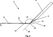
図1〜図3は、生物学的内腔に接近するためのデバイス(例えば、動脈切開デバイス2)を示す。動脈切開デバイス2は、送達ガイド4を有し得る。送達ガイド4は、アンカー6にスライド可能に取り付けられ得る。アンカー6は、剛性、可撓性、またはそれらの組み合わせであり得る。アンカー6は、弾力性、変形可能性またはそれらの組み合わせであり得る。アンカー6は、送達ガイド4から退却可能および拡張可能であり得る。送達ガイド4は、内腔導入器8を有し得る。内腔導入器8は、内腔導入器出口ポート10を有し得る。内腔導入器出口ポート10は、送達ガイド4の表面上に存在し得る。
(Detailed description and industrial applicability)
1-3 show a device (eg, arteriotomy device 2) for accessing a biological lumen. The
アンカー6は、アンカーアングル材部12を有し得る。アンカー6は、アンカー拡張部14(例えば、糸道の覆いまたは取り付け可能なガイドワイヤー)を有し得る。アンカー拡張部14は、アンカーアングル材部12から拡張し得る。アンカー拡張部14は、アンカーアングル材部12から分離、アンカーアングル材部12に取り付け、またはアンカーアングル材部12と一体化され得る。
The
アンカーアングル材部12は、アンカーアングル材の第1のサブセクション16、アンカー屈曲部20およびアンカーアングル材の第2のサブセクション18を有し得る。アンカーアングル材の第1のサブセクション16および/または第2のサブセクション18は、アンカー屈曲部20の部分であり得る。アンカー屈曲部20は、鋭いまたは緩やかなカーブを有し得る。アンカー屈曲部20についての曲率半径は、約0.1mm(0.004インチ)〜約2.0mm(0.079インチ)であり得る。
The
アンカーアングル材の第1のサブセクション16は、約0.38mm(0.015インチ)〜約1.0mm(0.039インチ)まで(例えば、約0.71mm(0.028インチ))のアンカーアングル材の第1のサブセクションの直径22を有し得る。アンカーアングル材の第2のサブセクション18は、約0.38mm(0.015インチ)〜約1.0mm(0.039インチ)まで(例えば、約0.71mm(0.028インチ))のアンカーアングル材の第2のサブセクションの直径24を有し得る。
The
アンカーアングル材の第1のサブセクション16は、送達長手方向軸26を有し得る。アンカーアングル材の第2のサブセクション18は、アンカー長手方向軸28を有し得る。送達長手方向軸26とアンカー長手方向軸28との交差部分は、アンカーアングル材30であり得る。アンカーアングル材30は、約20°〜約90°、より狭くは約30°〜約60°(例えば、約45°)であり得る。
The
本明細書中に記載される動脈切開デバイス2または他のデバイスまたは装置の任意のエレメントもしくは全てのエレメントは、例えば、単一または複数のステンレス鋼合金、ニッケルチタン合金(例えばニチノール)、コバルト−クロム合金(例えば、Elgin Specialty Metals,Elgin,ILから提供されるELGILOY(登録商標);Carpenter Metals Corp.,Wyomissing,PAから提供されるCONICHROME(登録商標))、モリブデン合金(例えば、2003年10月9日に公開された国際公開番号WO03/082363 A2(その全体が本明細書中に参考として援用される)に開示されるような例えば、モリブデンTZM合金)、例えば、国際公開番号WO03/082363に開示されるようなタングステン−レニウム合金、ポリエステル(例えば、E.I.Du Pont de Nemours and Company,Wilmington,DEから提供されるDACRON(登録商標))、ポリプロピレン、ポリテトラフルオロエチレン(PTFE)、発泡PTFE(ePTFE)、ポリエーテルエーテルケトン(PEEK)、ナイロン、ポリエーテルブロックコポリアミドポリマー(例えば、ATOFINA,Paris,Franceから提供されるPEBAX(登録商標))、脂肪族ポリエーテルポリウレタン(例えば、Thermedics Polymer Products,Wilmington,MAから提供されるTECOFLEX(登録商標))、ポリ塩化ビニル(PVC)、ポリウレタン、熱可塑性フッ素化エチレンプロピレン(FEP)のようなポリマー、ポリグリコール酸(PGA)、ポリ乳酸(PLA)、ポリジオキサノン、および擬似的ポリアミノ(pseudo−polyamino)チロシンベースの酸のような吸収性または再吸収性のポリマー、押出し成形されたコラーゲン、シリコーン、亜鉛、音波を発生する材料、放射性材料、放射線不透過性材料、あるいはそれらの組み合わせから作製され得る。放射性不透過性材料の例は、硫酸バリウム、酸化亜鉛、チタン、ステンレス鋼、ニッケルチタン合金、タンタルおよび金である。
Any or all elements of the
動脈切開デバイス2の任意の要素または全ての要素(伸長装置(tensioner)、クリップ、トグル、縫合糸、または本明細書中に記載される他のデバイスもしくは装置のような補助的な閉鎖デバイスを含む)は、細胞の内殖のためのマトリックスであり得るか、細胞の内殖のためのマトリックスを有し得るか、あるいは布地(例えば、細胞の内殖のためのマトリックスとして作用するカバー(示さず))とともに使用され得る。マトリックスおよび/または布地は、例えば、ポリエステル(例えば、E.I.du Pont de Nemours and Company,Wilmington,DEから提供されるDACRON(登録商標))、ポリプロピレン、PTFE、ePTFE、ナイロン、押出し成形されたコラーゲン、シリコーンまたはそれらの組み合わせであり得る。 Any or all elements of arteriotomy device 2 (including auxiliary closure devices such as tensioners, clips, toggles, sutures, or other devices or apparatus described herein) ) Can be a matrix for cell ingrowth, can have a matrix for cell ingrowth, or can be a fabric (eg, a cover (not shown) that acts as a matrix for cell ingrowth )). The matrix and / or fabric may be, for example, polyester (eg, DACRON® provided by EI du Pont de Nemours and Company, Wilmington, DE), polypropylene, PTFE, ePTFE, nylon, extruded. It can be collagen, silicone or a combination thereof.
動脈切開デバイスのエレメント2および/または布地は、当業者に公知の因子送達マトリックスおよび/または治療因子および/または診断因子で充填および/またはコーティングされ得る。これらのマトリックス内の因子としては、放射性材料;放射線不透過性材料;細胞発生因子;細胞障害性因子;細胞増殖抑制性因子;血栓形成性因子(例えば、ポリウレタン、三酸化ビスマスと混合された酢酸セルロースポリマー、およびエチレンビニルアルコール);つるつるした親水性材料;ホスホコレン(phosphor cholene);抗炎症因子(例えば、シクロオキシゲナーゼ−1(COX−1)インヒビター(例えば、アセチルサリチル酸(例えば、Bayer AG,Leverkusen,Germanyから提供されるASPIRIN(登録商標));イブプロフェン(例えば、Wyeth,Collegeville,PAから提供されるADVIL(登録商標);インドメタシン;メフェナム酸など)、COX−2インヒビター(例えば、Merck & Co.Inc.,Whitehouse Station,NJから提供されるVIOXX(登録商標);Pharmacia Corp.,Peapack,NJから提供されるCELEBREX(登録商標);COX−1インヒビター)のような非ステロイド性抗炎症因子(NSAID);免疫抑制性因子(例えば、Sirolimus(Wyeth,Collegeville,PAから提供されるRAPAMUNE(登録商標)))、または炎症性応答の経路内で初期に作用するマトリックスメタロプロテイナーゼ(MMP)インヒビター(例えば、テトラサイクリンおよびテトラサイクリン誘導体)が挙げられ得る。他の因子の例は、Waltonら、Inhibition of Prostoglandin E2 Synthesis in Abdominal Aortic Aneuryms,Circulation,1999年、7月6日、48−54:Tambiahら、Provocation of Experimental Aortic Inflammation Mediators and Chlamydia Pneumoniae,Brit.J.Surgery 88(7)、935−940;Franklinら、Uptake of Tetracycline by Aortic Aneurysm Wall and Its Effect on Inflammation and Proteolysis,Brit.J.Surgery 86(6)、771−775;Xuら、Sp1 Increases Expression of Cyclooxygenase−2 in Hypoxic Vascular Endothelium,J.Biological Chemistry 275(32)24583−24589;およびPyoら、Targeted Gene Disruption of Matrix Metalloproteinase−9(Gelatinase B)Suppresses Development of Experimental Abdominal Aortic Aneurysms,J.Clinical Investigation 105(11)、1641−1649(これらの全ては、その全体が本明細書中に参考として援用される)において提供される。
The
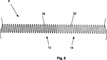
図4は、アンカーアングル材部12およびアンカー拡張部14は、可撓性の細長いエレメントを有し得ることを示す。この可撓性の細長いエレメントは、弾力的および/または変形可能であり得る。可撓性の細長いエレメントは、一体または複数の別々の、固定して取り付けられた曲がったワイヤ32を有し得る。アンカーアングル材部12は、覆い34中に存在し得る。図5は、アンカーアングル材部12が、ワイヤコーティング36(例えば、つるつるしたコーティングおよび/またはウレタンから作製されたコーティング)を有し得ることを示す。
FIG. 4 shows that the
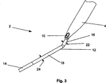
図6および図7は、動脈切開デバイス2が、導入デバイス38を有し得ることを示す。導入デバイス38は、内腔導入器8にスライド可能に取り付けられ得る。導入デバイス38は、中空のニードルを有し得る(図6に示される)。導入デバイス38は、中実のニードルを有し得る(図7に示される)。導入デバイス38は、ガイドワイヤーを有し得る。
6 and 7 show that the
導入デバイス38は、導入長手方向軸40を有し得る。導入長手方向軸40とアンカー長手方向軸28との交差部分は、導入角42であり得る。導入角42は、約19°未満または約19°、より狭くは約15°未満または約15°、さらにより狭くは約5°〜約10°(例えば、約10°)であり得る。
The
導入デバイス38は、導入デバイス直径44を有し得る。導入デバイス直径44は、約0.25mm(0.010インチ)〜約1.0mm(0.039インチ)(例えば、約0.56mm)(0.022インチ)であり得る。
図8および図9は、導入デバイス38がアンカー6から配置され得るように、動脈切開デバイス2が構造され得ることを示す。アンカー6は、導入デバイスポート46を有し得る。導入デバイス38は、中空のニードルであり得る(図8に示される)。完全に配置される場合、導入デバイス38は、内腔導入器の出口ポート10と接触し得る。導入デバイス38は、内腔導入器8とアンカー6との間のチャネルであり得る。アンカー6は、生物学的内腔と導入デバイス38とを連絡するように構造されるポート(示さず)を有し得る。導入デバイス38は、(図9に示すように)固体のニードルであり得る。
8 and 9 illustrate that the
図10は、内腔保持装置48が、第1の退却した構造を有し得ることを示す。内腔保持装置48は、内腔保持装置のポート50に静止され得る。内腔保持装置のポート50は、アンカー6に存在し得る。内腔保持装置48は、ワイヤ、足場またはステント(例えば、変形可能材料または弾力性材料(例えば、形状記憶合金)から作製されているもの)、膨張可能バルーン、あるいはそれらの組み合わせであり得る。管内の膨張可能バルーン(例えば、生理食塩水または二酸化炭素で膨張されるもの)は、当業者に公知である。内腔保持装置48は、送達ガイド4内に拡張され得る。
FIG. 10 shows that the
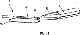
図11および図12は、内腔保持装置48が、第2の配置された構造を有し得ることを示す。図11は、内腔保持装置48が、ワイヤまたはバルーンであり得ることを示す。図12は、内腔保持装置48が、ワイヤであり得ることを示す。配置された構造において、内腔保持装置48は、内腔保持装置ポートから離れて配置され得る。内腔保持装置48は、内腔保持装置の配置されたときの直径52を有し得る。内腔保持装置の配置されたときの直径52は、約2.54mm(0.100インチ)〜約10.2mm(0.400インチ)(例えば、約6.35mm(0.250インチ))であり得る。
FIGS. 11 and 12 show that the
図13は、動脈切開デバイス2が、侵入壁保持装置ポート54を有し得ることを示す。侵入壁保持装置ポート54は、アンカー屈曲部20にあり得るか、アンカー屈曲部20付近であり得る。侵入壁保持装置ポート54は、アンカーアングル材の第1のサブセクション16にあり得るか、アンカー角の第1のサブセクション16付近であり得る。侵入壁保持装置ポート54は、動脈切開デバイス2の送達ガイド4に、または動脈切開デバイス2の送達ガイド4付近にセンサーまたはポート(示さず)を備える流体連絡中に存在し得る。
FIG. 13 shows that the
図14は、侵入壁保持装置56が、侵入壁保持装置ポート54を介して配置され得ることを示す。侵入壁保持装置56は、(図13に示されるように)第1の退却した構造を有し得る。侵入壁保持装置56は、(図14に示されるように)第2の配置された構造を有し得る。
FIG. 14 shows that the
図15〜図20は、種々の補助的な閉鎖デバイスを示す。これらの補助的な閉鎖デバイスは、完全または部分的に生体吸収性、生体再吸収性またはそれらの組み合わせであり得る。補助的な閉鎖デバイスは、同種移植片(homograft)、異種移植片またはそれらの組み合わせから作製され得る。補助的な閉鎖デバイスは、自家移植片、同種移植片(allograft)またはそれらの組み合わせから作製され得る。 15-20 show various auxiliary closure devices. These auxiliary closure devices can be fully or partially bioabsorbable, bioresorbable or a combination thereof. The auxiliary closure device can be made from a homograft, a xenograft or a combination thereof. The auxiliary closure device can be made from autograft, allograft, or combinations thereof.
図15は、伸長装置58を示す。伸長装置58は、弾力的、変形可能、またはそれらの組み合わせであり得る。伸長装置58は、伸長装置長手方向軸60を有し得る。伸長装置58は、ばねのような弾力性のあるエレメント(例えば、伸長装置ヘッド62)を有し得る。伸長装置ヘッド62は、伸長装置の第1のショルダー64を有し得る。伸長装置ヘッド62は、伸長装置の第2のショルダー66を有し得る。伸長装置の第1のショルダー64および第2のショルダー66は、それぞれ、別々または一体の伸長装置の第1のレッグ68および別々または一体の伸長装置の第2のレッグ70に回転可能に取り付けられ得る。伸長装置の第1のレッグ68および第2のレッグ70は、それぞれ、伸長装置の第1の足72および第2の足74に取り付けられ得る。
FIG. 15 shows the
伸長装置のレッグ68および70は、伸長装置のレッグの直径76を有し得る。伸長装置のレッグの直径76は、約0.1mm(0.005インチ)〜約0.76mm(0.030インチ)(例えば、約0.38mm(0.015インチ))であり得る。伸長装置の第1のレッグ68および第2のレッグ70は、伸長装置のレッグ間の外径78を有し得る。伸長装置のレッグ間の外径78は、約1.3mm(0.050インチ)〜約5.08mm(0.200インチ)(例えば、約4.06mm(0.160インチ))であり得る。伸長装置のショルダー64および/または66、ならびに/あるいは伸長装置のフィート72および/または74は、伸長装置の長手方向軸60から、それらのそれぞれの伸長装置のレッグ間の半径より大きい半径まで拡張され得る。
図16は、伸長装置の第1のレッグ68および伸長装置の第2のレッグ70に取り付け得る伸長装置の第1の支柱80を示す。伸長装置の第1のレッグ68は、弾力的、変形可能またはそれらの組み合わせであり得る。伸長装置の第2の支柱82は、伸長装置の第1のレッグ68および伸長装置の第2のレッグ70に取り付け得る。伸長装置の第2のレッグ70は、弾力的および/または変形可能であり得る。伸長装置58は、伸長装置ヘッド62を有さなくてもよい。伸長装置58は、2つより多い圧縮材80および82を有し得る。
FIG. 16 shows the first strut 80 of the stretcher that can be attached to the
図17は、圧力クリップ84を示す。圧力クリップ84は、弾力性であり得る。圧力クリップ84は、変形可能であり得る。圧力クリップ84は、圧力クリップの長手方向軸86を有し得る。圧力クリップ84は、圧力クリップヘッド88を有し得る。圧力クリップヘッド88は、別々または一体の圧力クリップの第1のレッグ90に回転可能に取り付けられ得る。圧力クリップヘッド88は、別々または一体の圧力クリップの第2のレッグ92に回転可能に取り付けられ得る。圧力クリップは、圧力クリップの第1の端部94および圧力クリップの第2の端部96を有し得る。圧力クリップの第1のレッグ90は、圧力クリップの第1の端部94において終端処理され得る。圧力クリップの第2のレッグ92は、圧力クリップの第2の端部96において終端処置され得る。圧力クリップの第1のレッグ90および/または圧力クリップの第2のレッグ92は、圧力クリップの長手方向軸86に向かって付勢され得る。
FIG. 17 shows the
図18は、圧力クリップの第2のレッグ92にスライド可能に取り付けられた圧力クリップ覆い98を有し得る圧力クリップ84を示す。圧力クリップの第1の端部94および/または第2の端部96は、平らおよび/または曲がった部分(例えば、円形のループ)のような圧力分散体であり得る。圧力クリップの第1の端部94および/または第2の端部96は、弾力的および/または変形可能であり得る。圧力クリップの第1のレッグ90は、圧力クリップの第2のレッグ92に回転可能に取り付けられ得る。圧力クリップの第1のレッグ90は、圧力クリップヘッド88における回転可能および/または変形可能および/または可撓性の接合部を介して、圧力クリップの第2のレッグ92に取り付けられ得る。
FIG. 18 shows a
図19は、トグル100を示す。トグル100は、トグルの第1の端部102を有し得る。トグル100は、トグルの第2の端部104を有し得る。トグルの第1の端部102および/またはトグルの第2の端部104は、棒、だぼ、さお、けた、またはそれらの組み合わせであり得る。トグル100は、フィラメント106を有し得る。フィラメント106は、フィラメントの第1の端部107においてトグルの第1の端部102に固定して取り付けられ得る。フィラメント106は、フィラメントの第2の端部109においてトグルの第2の端部104に固定して取り付けられ得る。フィラメント106は、弾力的または変形可能であり得る。フィラメント106は、実質的に可撓性であり得る。
FIG. 19 shows the
図20は、ホール108においてトグルの第2の端部104にスライド可能に取り付けられ得るフィラメント106を有し得るトグル100を示す。フィラメント106は、摩擦によりホール108にフィットし得る。フィラメント106は、爪110を有さなくてもよい(図20に示さず)。フィラメント106は、ホール108を締まりばめし得る。フィラメント106は、1つ以上の爪110を有し得る。ホール108は、1つ以上のノッチ112を有し得る。ノッチ112は、ホール108に対して内部であり得る。ノッチ112および爪110は、トグルの第2の端部104が、トグルの第1の端部102の方へスライドし得るように構造され得る。ノッチ112および爪110は、トグルの第2の端部104が、トグルの第1の端部102から離れて動くことを試みられるときに、締まりばめを提供するように構造され得る。
FIG. 20 shows a
(製造方法)
補助的な閉鎖デバイスを含む、動脈切開デバイス2のエレメントは、例えば、融解、ネジ止め、接着、溶接、または締りばめもしくはプレスばめ(例えば、クリンピング、スナッピング)の使用、またはそれらの組み合わせ方法によって直接的に取り付けられ得る。エレメントは、例えば、成形、打抜き、レーザー切断、放電加工(EDM)または単一の片もしくは材料からのスタンピングによって、一体化され得る。任意の他の方法が、当業者に公知のように使用され得る。
(Production method)
The elements of the
一体化部品は、予め形成される弾力性のある材料(例えば、当業者に公知のような予め形成されて配置後の形状にゆがみ、次いで配置形状に圧縮される弾力性合金(例えば、ニチノール、ELGILOY(登録商標)))から作製され得る。 The integral part is a pre-formed elastic material (e.g., a pre-formed elastic alloy (e.g., nitinol, ELGILOY®)).
補助的な閉鎖デバイスを含む、動脈切開デバイス2の任意のエレメント、または補助的な閉鎖デバイスを含む、組立て後の全体としての動脈切開デバイス2は、当業者に公知の浸漬被覆法、ブラシ被覆法または噴霧被覆法によってコーティングされ得る。例えば、これらの方法は、巻かれたワイヤ32をコーティングするために使用され得、他方ワイヤコーティング36が、ワイヤ32上に噴霧被覆、浸漬被覆またはブラシ被覆され得る。
Any element of the
血管使用のための医療デバイスをコーティングするために使用される1つの例は、Dingらによって米国特許第6,358,556号に提供される。この特許文献の全体が本明細書中に参考として援用される。当業者に公知の徐放コーティング法もまた、コーティング(例えば、補助的な閉鎖デバイス上のコーティング)における因子の放出を遅らせるために使用され得る。 One example used to coat medical devices for vascular use is provided by Ding et al. In US Pat. No. 6,358,556. The entirety of this patent document is incorporated herein by reference. Sustained release coating methods known to those skilled in the art can also be used to delay the release of factors in a coating (eg, a coating on an auxiliary closure device).
補助的な閉鎖デバイスは、繊維(例えば、ポリエステル(例えば、E.I.du Pont de Nemours and Company,Wilmington,DEから提供されるDACRON(登録商標))、ポリプロピレン、PTFE、ePTFE、ナイロン、押出し成形されたコラーゲン、シリコーンまたはそれらの組み合わせ)で覆われ得る。繊維を備える移植可能デバイスを含む方法は、当業者に公知である。 Auxiliary closure devices include fibers (eg, polyesters (eg, DACRON® from EI du Pont de Nemours and Company, Wilmington, DE), polypropylene, PTFE, ePTFE, nylon, extrusion. Coated collagen, silicone or combinations thereof). Methods involving implantable devices comprising fibers are known to those skilled in the art.
(使用方法)
図21は、生物学的内腔114(例えば、大腿動脈のような血管)にアンカー6を挿入する方法を示す。生物学的内腔114は、内腔壁116および内腔壁面118を有し得る。アンカー6は、セルディンガー法、改変セルディンガー法、または当業者に公知の他の方法を用いて生物学的内腔114に挿入され得る。アンカー6は、第1の動脈切開120を作り出し得る。アンカー6は、アンカーアングル部材の第2のサブセクション18が、内腔壁面118と実質的に平行であり得るように内腔114に挿入され得る。アンカー6は、アンカーアングル部材の第2のサブセクション18が、内腔壁面118と実質的に接触し得るように、内腔114に挿入され得る。
(how to use)
FIG. 21 illustrates a method of inserting the
図22は、矢印によって示されるように、第1の退却した構造から第2の配置された構造までの内腔保持装置48を配置する方法を示す。内腔保持装置48は、ワイヤ、足場またはステントを拡張することによって、あるいはバルーンを膨張させることによって配置され得る。内腔保持装置48が配置される場合、アンカーアングル部材の第2のサブセクション18は、内腔壁面118と実質的に平行に作製され得る。内腔保持装置48が配置される場合、アンカーアングル部材の第2のサブセクション18は、内腔壁面118と実質的に接触するように作製され得る。
FIG. 22 illustrates a method of placing the
図23は、矢印122によって示されるように、第1の退却した構造から第2の配置された構造までの侵入壁の保持装置56を配置する方法を示す。内腔保持装置が第2の配置された構造に存在する場合、内腔保持装置48は、内腔壁面118と実質的に平行であり得る。内腔保持装置が第2の配置された構造に存在する場合、内腔保持装置48は、内腔壁面118と実質的に接触し得る。
FIG. 23 illustrates a method of placing the
矢印124によって示されるように、近位方向の力が、(例えば、送達ガイド4に付与されることによって)アンカー6に付与され得る。近位方向の力が付与される場合、アンカーアングル部材の第2のサブセクション18は、内腔壁面118と実質的に平行に作製され得る。近位方向の力が付与される場合、アンカーアングル部材の第2のサブセクション18は、内腔壁面118と実質的に接触して作製され得る。
A proximal force may be applied to the anchor 6 (eg, by being applied to the delivery guide 4), as indicated by
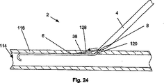
図24および図25は、導入デバイス38を配置するための方法を示す。導入デバイス38は、内腔導入器8および内腔導入器出口ポート10から出ていき得る。図24に示されるように、導入デバイス38は、矢印によって示されるように、内腔壁116の中および内腔壁116を介して押出され得る。導入デバイス38は、第2の動脈切開128を形成し得る。図25に示されるように、導入デバイス38は、矢印によって示されるように、アンカー6に隣接して、またはアンカー6を介して押出され得る。アンカー6は、導入デバイス38が、アンカー6を通過し得るのに適切なポートを有するように構造され得る。導入デバイス38の先端部は、内腔壁114に入り得る。
FIGS. 24 and 25 illustrate a method for placing the
導入デバイス38は、導入幅132および導入深さ134を通過し得る。導入幅132は、内腔壁116に対して平行である内腔壁116における導入デバイス38の長さの成分であり得る。導入幅132は、内腔壁116の外側上の第2の動脈切開128の開口部と、内側の内腔壁面118上の第2の動脈切開128の開口部との間の内腔壁116に平行な長さの成分であり得る。導入幅132は、約0.10cm(0.010インチ)〜約3.810cm(1.500インチ)(例えば、約0.64cm(0.25インチ))であり得る。
The
導入深さ134は、内腔壁116に対して垂直である内腔壁116における導入デバイス38の長さの成分であり得る。導入深さ134は、内腔壁116の外側上の第2の動脈切開128の開口部と、内側の内腔壁面118上の第2の動脈切開128の開口部との間の内腔壁116に対して垂直である長さの成分であり得る。導入深さ134は、約0.51mm(0.020インチ)〜約5.08mm(0.200インチ)(例えば、約1.0mm(0.040インチ))であり得る。導入スロープは、導入幅132に対する導入深さ134との比であり得る。導入スロープは、約2分の1〜約40分の1以下(例えば、約6分の1、また例えば約3分の1)であり得る。導入スロープは、例えば、約2分の1以下または3分の1以下、より狭くは約3分の1以下または4分の1以下、さらにより狭くは約5分の1以下または6分の1以下、なおさらにより好ましくは約10分の1以下であり得る。
The
導入深さ134および導入幅132は、導入ベクトルの成分であり得る。導入幅132は、内腔壁116に対して平行である導入ベクトルの成分であり得る。導入深さ134は、内腔壁116に対して垂直である導入ベクトルの成分であり得る。導入ベクトルは、外側の開口部136から内側の開口部138までのベクトルであり得る。外側の開口部136は、導入デバイス38によって形成される内腔壁116の一時的または永久的な開口部であり得る。内側開口部138は、血管壁の内側上の一時的または永久的な開口部であり得る。
The
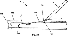
図26は、導入デバイス38(例えば、内腔ツール(例えば、矢印によって示されるように、内腔114に配置されるガイドワイヤー168のようなツール)についての経路として作用し得る中空ニードル)を示す。導入デバイス38(例えば、固体ニードル)は、第2の動脈切開128から取り除かれ得、内腔ツールは、例えば、内腔導入器の出口ポート10、および第2の動脈切開128を介して配置され得る。導入デバイス38は、内腔ツール(例えば、ガイドワイヤー)であり得る。導入デバイス38は、内腔壁116を通過後、内腔ツールとしてさらに配置されて、使用され得る。
FIG. 26 shows an introduction device 38 (eg, a hollow needle that can act as a pathway for a lumen tool (eg, a tool such as a
図27から図30は、予め形成される屈曲部を有し得る導入デバイス38を配置する方法を示す。図27に示すように、動脈切開デバイス2は、約0°〜約5°(例えば、約0°)の導入角42にて導入デバイス38を配置するために構造され得る。
FIGS. 27-30 illustrate a method of placing an
図28に示されるように、導入デバイス38は、矢印によって示されるように、内腔壁116を介して、押し出され得る。導入デバイス38は、内腔壁116において面を切断し得る。面は、内腔壁面118に対して実質的に平行であり得る。導入デバイス38は、血管中の外膜に隣接し得る。導入デバイス38は、血管中の内膜下または亜正中の切断面に沿って進行され得る。一旦、内腔壁が切断されると、内膜下の血管形成が、当業者に公知のように実施され得る。一旦、内腔壁が切断されると、遠隔性の動脈内膜切除が、当業者に公知のように実施され得る。曲がった導入デバイス38およびまっすぐな導入デバイス38は、使用中、内腔壁116を選択的に切断するために交換され得る。ガイドワイヤーのようなツールは、選択的に内腔壁116を切断するために、中空の導入デバイス38を介して挿入され得る。
As shown in FIG. 28,
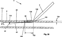
図29に示されるように、導入デバイス38の屈曲部が、内腔壁116の中に動く場合、導入デバイス38は、矢印によって示すように、生物学的内腔114の方へ回転し得る。図30に示されるように、導入デバイス38の屈曲部は、生物学的内腔114の方へ導入デバイス38を回転し続け得る。以下に記載するように、導入デバイス38は、内腔114に入り得る。図31は、導入デバイス38が、以下に記載するように、内腔ツールについての経路として作用し得る屈曲部を有し得ることを示す。
As shown in FIG. 29, when the bend of the
導入覆いは、ガイドワイヤー168および/または導入デバイス38の上に挿入され得る。導入覆いは、約22フレンチ(7.3mm、0.29インチ直径)未満、または導入覆いが導入される内腔の直径未満であり得る。導入覆いは、例えば、約6フレンチ(2.3mm、0.092インチ直径)、および約8フレンチ(2.67mm、0.105インチ直径)であり得る。導入覆いは、当業者に公知であり得る(例えば、導入覆いは、Dubrulらによる米国特許第5,183,464号に記載される)。
An introducer wrap may be inserted over
導入覆いは、第2の動脈切開128の中に挿入され得る。導入覆いは、第2の動脈切開128を作用可能なサイズに拡張し得る。導入覆いは、補助的な閉鎖デバイスが配置、そして/または他の閉鎖方法が使用される前および/または後および/または同時に第2の動脈切開128の中に挿入され得る。
An introducer wrap can be inserted into the
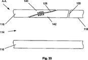
図32および図33は、動脈切開デバイス2が配置されて、生物学的内腔114から取り除かれた後の例示的な生物学的内腔114を示す。生物学的内腔114は、第1の動脈切開120および第2の動脈切開128を有し得る。生物学的内腔114は、第2の動脈切開128を有し得る。生物学的内腔114は、動脈切開(第2の動脈切開128として示す)の片側に第1のウェブ140、および動脈切開120または128の反対側に第2のウェブ142を有し得る。矢印によって示されるように、第1のウェブ140および第2のウェブ142からの自然の圧力が、動脈切開120または128を自己封入し得る。
32 and 33 show an exemplary
1つ以上の補助的な閉鎖デバイスが、第1の動脈切開120および/または第2の動脈切開128に配置され得る。補助的な閉鎖デバイスが、力または止血に役立つための制限を提供し得る。補助的な閉鎖デバイスは、永久的または一時的に配置され得る。補助的な閉鎖デバイスは、止血が達成された後、そして/または関連する動脈切開120もしくは128が、実質的または完全に治療された後、生体溶解し得る。補助的な閉鎖デバイスからの力は、約15分〜約24時間以上(例えば、約120分間)、維持され得る。
One or more auxiliary closure devices can be placed in the
図34は、圧縮された構造の伸長装置58を示す。矢印によって示されるように、圧縮力は、伸長装置の第1のレッグ68および第2のレッグ70を圧縮し得る。圧縮された構造において、伸長装置のレッグ間の外径78は、約0.51mm(0.020インチ)〜約2.54mm(0.100インチ)(例えば、約1.5mm(0.060インチ))であり得る。
FIG. 34 shows the
図35および図36は、伸長装置58を配置する方法を示す。図35に示されるように、伸長装置58は、圧縮された構造であり得る。伸長装置58は、矢印144によって示されるように、圧縮力に曝露され得る。圧縮力は、取り外し可能な覆い、クランプ、当業者に公知の他の方法、またはそれらの組み合わせによって、付与され得る。配置の力は、矢印146によって示されるように、伸長装置58を動脈切開120または128の中に配置し得る。
FIGS. 35 and 36 show a method of placing the stretching
動脈切開120または128は、動脈直径148を有し得る。動脈直径148は、約0.5mm(0.020インチ)〜約400mm(15インチ)、さらにより狭い範囲で約1.0mm(0.040インチ)〜約10.2mm(0.400インチ)(例えば、約2.54mm(0.100インチ))であり得る。圧縮された構造の場合、伸長装置のレッグ間の外径78は、動脈直径148より小さくなり得る。伸長装置の第1のショルダー64および第2のショルダー66は、動脈切開120または128を締まりばめするのに十分な広さであり得る。伸長装置の第1のショルダー64および第2のショルダー66は、内腔壁面118上の力を分散し得る。
図36に示されるように、圧縮力は、伸張装置58から取り除かれ得る。伸張装置の第1および第2のレッグ68および70は、矢印で示されるように、拡張し得る。伸張装置58は、動脈切開120または128を実質的または完全に平坦な構造、および/または閉じた構造および/または引き伸ばされた構造へと押し得る。動脈切開120または128の壁は、密接に接触し得る。
As shown in FIG. 36, the compressive force can be removed from the stretching
動脈切開120または128は、動脈切開幅150および動脈切開高さ152を有し得る。動脈切開幅150は、動脈切開120または128の周囲の約半分であり得る。動脈切開幅150は、約1.0mm(0.040インチ)〜約10.2mm(0.400インチ)、例えば約4.06mm(0.16インチ)であり得る。
動脈切開高さ152は、ほぼ伸張装置の足の直径76であり得る。動脈切開高さ152は、約0.51mm(0.020インチ)未満、より狭くは約0.38mm(0.015インチ)未満であり得る。動脈切開高さ152は、約0.25mm(0.010インチ)〜約1.3mm(0.050インチ)、例えば約0.38mm(0.015インチ)であり得る。動脈切開高さ152は、動脈切開120または128にわたる細胞増殖、血餅形成、音響シール、熱シール、接着、増強された自己封入およびこれらの組合せを可能にするに十分小さくあり得る。
The
伸張装置の第1および第2のショルダー64および66は、動脈切開120または128と締まり嵌めするに十分な広さであり得る。伸張装置の第1および第2の足72および74は、動脈切開120または128と締まり嵌めするに十分な広さであり得る。伸張装置の第1および第2の足72および74は、内腔壁面118上の力を分散し得る。
The first and
上記および下記の補助的な閉鎖デバイス、自己封入性閉鎖方法、またはこれらの組合せのいずれかを使用する前に、動脈切開120または128は、栓をされ、そして/または詰め物をされ、そして/またはタンポン挿入され得る。栓、詰め物、タンポンまたはこれらの組合せ(示さず)は、ゲルフォーム、コラーゲン、または当業者に公知の他の移植可能かつ生体適合性のタンポン材料、またはこれらの組合せから作製され得る。
Prior to using any of the supplemental closure devices described above and below, self-encapsulating closure methods, or combinations thereof, the
図37〜40は、動脈切開120または128に圧力クリップ84を配置する工程を図示する。図37は、圧力クリップの第2の端部96を拡張し、そして/または薄くし、そして/または真直ぐにし、そして/または伸張する工程を図示する。圧力クリップの覆い98は、矢印により示されるように、圧力クリップの第2のレッグ92に沿って、そして圧力クリップの第2の端部96の上へ移動され得る。圧力クリップの第2の端部96が拡張され、そして/または薄くされ、そして/または真直ぐにされ、そして/または伸張された後、圧力クリップ84は、動脈切開に配置され得る。
37-40 illustrate the process of placing the
図38に示されるように、圧力クリップの第2のレッグ92は、圧力クリップの第2のレッグ92および圧力クリップヘッド88が実質的に整列するように、圧力クリップヘッド88に対して回転され得る。圧力クリップの第2のレッグ92は、矢印により示されるように、第1の動脈切開120を通して配置され得る。(例えば、既存の第1の動脈切開120が存在しない場合、第1の動脈切開120が第2の動脈切開128に対して適切に位置決めされていない場合)圧力クリップの第2のレッグ92は、内腔壁116を通して配置され得る。
As shown in FIG. 38, the pressure clip
図39は、圧力クリップの第2の端部96を縮小し、そして/または幅を広げ、そして/または開放し、そして/または弛緩させる工程を図示する。圧力クリップの覆い98は、矢印により示されるように、圧力クリップの第2のレッグ92に沿って、そして圧力クリップの第2の端部96から離れて移動され得る。圧力クリップの第2の端部96は、圧力クリップ84が動脈切開に配置された後、縮小され、そして/または幅を広げられ、そして/または開放され、そして/または弛緩され得る。
FIG. 39 illustrates the steps of shrinking and / or widening and / or opening and / or relaxing the
図40に示されるように、圧力クリップの第2のレッグ92が第1の動脈切開120を通して配置された後、圧力クリップの第2のレッグ92は、圧力クリップヘッド88に対して回転するように、開放されるかまたは変形され得る。圧力クリップヘッド88は、第1の動脈切開120中に静止し得る。圧力クリップの第1のレッグおよび第2のレッグ90および92は、矢印により示されるように、それぞれ、第1のウェブ140および第2のウェブ142に力を付与し得る。
As shown in FIG. 40, after the
図41および42は、動脈切開120または128を取り囲み、そして/またはそれを通るステッチ154を設置する方法を図示する。ステッチ154は、動脈切開120または128にさらなる圧力を付与するように堅く結ばれ得る。ステッチ154は、結び目156、または他の結束構造または結束デバイス(例えば、外科用綿撒糸またはクランプ)であり得る。
41 and 42 illustrate a method of placing a
図43および44は、動脈切開120または128に隣接して、および/またはそれを通してフィラメント106を配置する方法を図示する。フィラメント106は、第1の結び目156aまたは他の結束構造または結束デバイスにより第1の綿撒糸158aに取り付けられ得る。フィラメント106は、第2の結び目156bまたは他の結束構造または結束デバイスにより第2の綿撒糸158bに取り付けられ得る。第1および第2の綿撒糸158aおよび158bは、当業者に公知の他の圧力拡散装置(例えば、上記または下記のトグル100)であり得る。
43 and 44 illustrate a method of placing the
図45および46は、第1の退却構造にあり得るトグル配置デバイス159を図示する。トグル配置デバイス159は、圧力チェックポート160を有し得る。圧力チェックポート160は、トグル配置デバイス159のハンドル(示さず)の上、またはその近くのセンサーまたはポート(例えば、外部チューブまたはポートの端部からの流れ、および/または透明な窓または半透明の窓を通る流れから、血流が観察され得る外腔のようなもの)と流体連通にあり得る。圧力チェックポート160は、例えば圧力チェックポート160が生物学的内腔114に入るとき、圧力チェックポートが導入されて圧力がかかる場所への、トグル配置デバイス159の配置を容易にし得る。トグル配置デバイス159のハンドル(示さず)の上、またはその近くのセンサーまたはポートは、(例えば、少量の血流を表示することにより)圧力チェックポート160が生物学的内腔114の中に配置されたという信号を送る。圧力チェックポート160は、生物学的内腔114の中に配置され得、次いで生物学的内腔114から、内腔壁116が圧力チェックポート160中の圧力をちょうど止める点まで引き込められ得る。進入壁保持装置ポート54は、さらに圧力チェックポート160について本明細書中で記載されたような機能を果たし得る。トグル配置デバイス159は、送達ニードルポート161を有し得る。
45 and 46 illustrate a
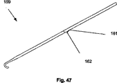
図47および48は、第2の送達構造にあり得るトグル配置デバイス159を図示する。送達ニードル162は、トグル配置デバイス159にスライド可能に取り付けられ得る。トグル配置デバイス159が第2の送達構造にあるとき、送達ニードル162は、送達ニードルポート161を出て行き得る。
47 and 48 illustrate a
図49および50は、トグル配置デバイス159が、圧力チェックポート160が生物学的内腔114中に位置決めされ得る位置で動脈切開120または128の中へと配置され得ることを図示する。送達ニードルポート161は、内腔壁116の中、またはそれに隣接して存在し得る。
49 and 50 illustrate that the
図51および図52は、トグル配置デバイス159が第2の送達構造に置かれ得ることを図示する。トグル配置デバイス159が第2の送達構造に配置されるときに送達ニードルポートが内腔壁116の中、またはそれに隣接して存在する場合は、送達ニードル162は、内腔壁116に入り得る。例えば、送達ニードル162は、第2のウェブ142に入り得る。送達ニードル162は、第2のウェブ142を出て行き得、そして矢印により示されるように、生物学的内腔114に入り得る。
51 and 52 illustrate that the
図53は、プッシャー164が送達ニードル162にスライド可能に取り付けられ得ることを図示する。送達ニードル162は、ニードル先端ポート166を有し得る。トグル100は、送達ニードル162の中に存在し得る。トグル100は、トグルの第1の端部102がプッシャー164のニードル先端ポート166側に位置決めされ得るように、送達ニードル162の中に配置され得る。
FIG. 53 illustrates that the
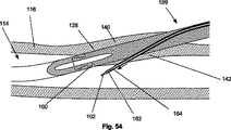
図54は、プッシャー164は、矢印により示されるように、ニードル先端ポート166に向かって移動され得る。送達ニードル162は、プッシャー164に対して逆に動かされ得、プッシャー164は、送達ニードル162に対して前方向に移動され得、またはそれらの組合せであてもよい。プッシャー164は、送達ニードル162から外へトグルの第1の端部102を押し得る。プッシャー164は、トグルの第1の端部102を生物学的内腔114の中へ押し得る。
54, the
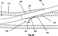
図55および56は、トグルの第1の端部102を生物学低内腔114中に配置した後は、トグル配置デバイス159が第1の退却構造にあり得ることを図示する。送達ニードル162がトグル配置デバイス159の中に退却すると、トグルの第2の端部104は、トグル配置デバイス159の中に存在し得る。フィラメント106は、送達ニードルポート161を通って延び得る。
55 and 56 illustrate that after the
図57および58は、トグル100は、内腔壁を横切って配置され得ることを図示する。トグル配置デバイス159が動脈切開から取り除かれるとき、トグルの第2の端部104は、送達ニードルポート161から内腔壁116の外側に配置し得る。トグルの第1の端部102は、内腔壁表面118と締まり嵌めを形成し得る。トグルの第2の端部104は、内腔壁116の外側またはその周囲の組織(例えば、皮下組織)と締まり嵌めを形成し得る。トグルの第2の端部104は、例えば図20に図示されるトグル100のように、フィラメント106に沿って内腔壁116に向かってスライド可能に並進し得る。トグルの第1の端部102からトグルの第2の端部104の反対側のフィラメント106の長さは、切断され得、折られ得、または別の方法で取り除かれ得る。
57 and 58 illustrate that the
図59〜63は、トグル100を配置する方法を図示する。送達ニードル162は、矢印で示されるように、トグル配置送達ポート163から出得る。トグル配置送達ポート163は、送達ガイド4の中に存在し得る。送達ニードル162は、内腔114に向かって前進され得る。
59-63 illustrate a method of placing the
図60は、送達ニードル162が内腔壁を通して配置され得ることを図示する。送達ニードル162が内腔壁116を通して配置される場合、その送達ニードルは、第2の動脈切開を横断またはその近くを通過し得る。
FIG. 60 illustrates that the
図61および62は、矢印で示されるように、送達ニードル162を通してプッシャー164が前進され得ることを図示する。トグルの第1の端部102は、ニードル先端ポート166から出て行き得る。トグルの第1の端部102は、内腔114の中に配置し得る。
61 and 62 illustrate that the
図63は、送達ニードル162が、送達ガイド4の中に退却され得、そして/またはフィラメント106がぴんと(taught)引張られ得る(両方とも、矢印により示される)ことを図示する。トグルの第1の端部102は、内腔壁表面118と締り嵌めを形成し得る。トグルの第2の端部104(図63には示さず)は、フィラメント106の上をスライド可能に内腔壁116の外側まで並進され、そしてそれと締り嵌めを形成し得る。トグルの第1の端部102からトグルの第2の端部104の反対側のフィラメント106の長さは、切断され得、折られ得、または別の方法で取り除かれ得る。
FIG. 63 illustrates that the
図64は、矢印により示されるように、例えばSeldinger技術を使用して、端部が内腔壁116を通って内腔114の中に挿入されている導入ニードル165を図示する。導入ニードル165は、中空であってよく、そして/または長手方向チャネルを有し得る。図65は、ガイドワイヤ168が、矢印により示されるように、導入ニードル165の中空かつ/または長手方向のチャネルを通して配置され得ることを図示する。
FIG. 64 illustrates an
図66は、矢印により示されるように、導入ニードル165が内腔壁116から取り除かれ得ることを図示する。ガイドワイヤ168は、実質的に適所に留まり得る。導入ニードル165が取り除かれた後、ガイドワイヤ168の一部は、内腔114の外側にあり得、そしてガイドワイヤ168の別の部分はない腔114の内側にあり得る。
FIG. 66 illustrates that the
図67は、ガイドワイヤ168をアンカー6に固定して、またはスライド可能に取付ける方法を図示する。ガイドワイヤの近位端170は、アンカーの遠位端172の近くに配置され得る。ガイドワイヤの近位端170は、次いで、矢印により示されるように、アンカーの遠位端172に取付けられ得る。ガイドワイヤ168のいくつかまたはすべてが内腔114中にある間に、ガイドワイヤの近位端170は、アンカーの遠位端172に取付けられ得る。ワイドワイヤの近位端170は、アンカー6に対して、スナップ嵌め、締り嵌め、スライド可能に取付け、またはこれらの組合せとなるように構造され得る。ガイドワイヤ168がアンカー6に取付けられる場合、ガイドワイヤ168はアンカー伸長部セクション14および/または内腔ツールとして作用し得る。図68は、アンカー6に取付けられたガイドワイヤ168を図示する。
FIG. 67 illustrates a method of securing or slidably attaching
適用可能な場合、任意の補助的な閉鎖デバイスを配置するための上に記載された方法は、他の補助的な配置デバイスのいずれかを配置するために使用され得る。本発明の趣旨および範囲を逸脱することなく種々の変更および改変が本開示に対してなされ得、等価物が採用されることが当業者には明らかである。あらゆる実施形態とともに示された要素は、具体的な実施形態のための例示のためのものであり、本開示内の他の実施形態について使用され得る。 Where applicable, the methods described above for placing any auxiliary closure device may be used to place any of the other auxiliary placement devices. It will be apparent to those skilled in the art that various modifications and variations can be made to the present disclosure and equivalents can be employed without departing from the spirit and scope of the invention. Elements shown with any embodiment are for illustration for a specific embodiment and may be used for other embodiments within the present disclosure.
Claims (12)
a.第1の動脈切開を通って該壁を横切り、そして該内腔中に挿入されるよう構成されたアンカー;および
b.該アンカーに作動可能に連結され、そして該壁を横切って挿入されるよう構成された導入器であって、該導入器は、該アンカーに力が付与されて該血管を該導入器に対して所望の形態に配置するとき、該内腔に至る通路を形成し、該通路が該第1の切開から分離されている、導入器;を備え、該通路は、つぶれて自己封入する、システム。A system for forming a self-contained opening through the wall of a blood vessel defining a lumen comprising :
a. An anchor configured to traverse the wall through a first arteriotomy and to be inserted into the lumen; and
b. An introducer operably coupled to the anchor and configured to be inserted across the wall , wherein the introducer is configured to apply force to the anchor to force the blood vessel relative to the introducer; when placed in the desired form to form a passage leading to the lumen, passage is that is separated from the incision of the first introducer; includes a passageway is self sealed collapse, system.
Applications Claiming Priority (3)
| Application Number | Priority Date | Filing Date | Title |
|---|---|---|---|
| US10/844,247 | 2004-05-12 | ||
| US10/844,247 US20050267520A1 (en) | 2004-05-12 | 2004-05-12 | Access and closure device and method |
| PCT/US2005/016623 WO2005112791A2 (en) | 2004-05-12 | 2005-05-12 | Access and closure device and method |
Related Child Applications (2)
| Application Number | Title | Priority Date | Filing Date |
|---|---|---|---|
| JP2008123950A Division JP2008253791A (en) | 2004-05-12 | 2008-05-09 | Access and closure device and method |
| JP2010181964A Division JP2011005270A (en) | 2004-05-12 | 2010-08-16 | Access and closure device and method |
Publications (3)
| Publication Number | Publication Date |
|---|---|
| JP2008500071A JP2008500071A (en) | 2008-01-10 |
| JP2008500071A5 JP2008500071A5 (en) | 2010-10-21 |
| JP4871268B2 true JP4871268B2 (en) | 2012-02-08 |
Family
ID=35426402
Family Applications (5)
| Application Number | Title | Priority Date | Filing Date |
|---|---|---|---|
| JP2007513356A Expired - Fee Related JP4871268B2 (en) | 2004-05-12 | 2005-05-12 | Access and closure devices and methods |
| JP2008123950A Withdrawn JP2008253791A (en) | 2004-05-12 | 2008-05-09 | Access and closure device and method |
| JP2010181964A Pending JP2011005270A (en) | 2004-05-12 | 2010-08-16 | Access and closure device and method |
| JP2012061872A Pending JP2012130766A (en) | 2004-05-12 | 2012-03-19 | Access and closure device and method |
| JP2013170128A Pending JP2013255826A (en) | 2004-05-12 | 2013-08-20 | Access and closure device and method |
Family Applications After (4)
| Application Number | Title | Priority Date | Filing Date |
|---|---|---|---|
| JP2008123950A Withdrawn JP2008253791A (en) | 2004-05-12 | 2008-05-09 | Access and closure device and method |
| JP2010181964A Pending JP2011005270A (en) | 2004-05-12 | 2010-08-16 | Access and closure device and method |
| JP2012061872A Pending JP2012130766A (en) | 2004-05-12 | 2012-03-19 | Access and closure device and method |
| JP2013170128A Pending JP2013255826A (en) | 2004-05-12 | 2013-08-20 | Access and closure device and method |
Country Status (8)
| Country | Link |
|---|---|
| US (8) | US20050267520A1 (en) |
| EP (4) | EP1748735A4 (en) |
| JP (5) | JP4871268B2 (en) |
| CN (2) | CN101431948B (en) |
| AU (1) | AU2005244834A1 (en) |
| CA (1) | CA2566743A1 (en) |
| IL (2) | IL179173A (en) |
| WO (1) | WO2005112791A2 (en) |
Families Citing this family (59)
| Publication number | Priority date | Publication date | Assignee | Title |
|---|---|---|---|---|
| US7410480B2 (en) * | 2004-04-21 | 2008-08-12 | Acclarent, Inc. | Devices and methods for delivering therapeutic substances for the treatment of sinusitis and other disorders |
| US20050251178A1 (en) * | 2004-05-03 | 2005-11-10 | Tirabassi Michael V | Hooked rod delivery system for use in minimally invasive surgery |
| US20050267520A1 (en) | 2004-05-12 | 2005-12-01 | Modesitt D B | Access and closure device and method |
| US7678133B2 (en) | 2004-07-10 | 2010-03-16 | Arstasis, Inc. | Biological tissue closure device and method |
| US7753935B2 (en) * | 2005-04-29 | 2010-07-13 | Vivasure Medical Limited | Interventional medical closure device |
| US8241325B2 (en) | 2005-05-12 | 2012-08-14 | Arstasis, Inc. | Access and closure device and method |
| US20060270989A1 (en) * | 2005-05-27 | 2006-11-30 | Mcmichael Donald J | Gastric fastening system |
| US7549200B2 (en) * | 2005-05-27 | 2009-06-23 | Kimberly-Clark Worldwide, Inc. | Clamp for flexible tube |
| US20100168767A1 (en) * | 2008-06-30 | 2010-07-01 | Cardiva Medical, Inc. | Apparatus and methods for delivering hemostatic materials for blood vessel closure |
| US8911472B2 (en) | 2005-12-13 | 2014-12-16 | Cardiva Medical, Inc. | Apparatus and methods for delivering hemostatic materials for blood vessel closure |
| US20080097491A1 (en) * | 2006-08-28 | 2008-04-24 | Fred Gobel | Tissue to tissue anchoring device and method of using the same |
| US7582098B2 (en) * | 2006-08-28 | 2009-09-01 | Kimberly-Clark Wolrdwide, Inc. | Percutaneous gastrointestinal anchoring kit |
| WO2008027366A2 (en) * | 2006-08-28 | 2008-03-06 | Vascular Precision | Devices and methods for creating and closing controlled openings in tissue |
| EP2166953B8 (en) | 2007-06-15 | 2018-11-07 | Vivasure Medical Limited | A closure device |
| US8858490B2 (en) | 2007-07-18 | 2014-10-14 | Silk Road Medical, Inc. | Systems and methods for treating a carotid artery |
| US20090105744A1 (en) * | 2007-10-17 | 2009-04-23 | Modesitt D Bruce | Methods for forming tracts in tissue |
| US10376261B2 (en) | 2008-04-01 | 2019-08-13 | Covidien Lp | Anchoring suture |
| US9358002B2 (en) * | 2008-04-01 | 2016-06-07 | Covidien Lp | Anchoring device |
| AU2009269566A1 (en) * | 2008-07-07 | 2010-01-14 | Apica Cardiovascular Ireland Limited | Tissue access site system and method |
| WO2010011696A1 (en) | 2008-07-21 | 2010-01-28 | Arstasis, Inc. | Devices and methods for forming tracts in tissue |
| CN102159126A (en) * | 2008-07-21 | 2011-08-17 | 阿尔斯塔西斯公司 | Devices, methods, and kits for forming tracts in tissue |
| US8574245B2 (en) | 2008-08-13 | 2013-11-05 | Silk Road Medical, Inc. | Suture delivery device |
| EP2323566A2 (en) | 2008-08-13 | 2011-05-25 | Silk Road Medical, Inc. | Suture delivery device |
| WO2010107698A2 (en) * | 2009-03-14 | 2010-09-23 | Vasostitch, Inc. | Vessel access and closure device |
| CN102802541A (en) * | 2009-05-15 | 2012-11-28 | 阿尔斯塔西斯公司 | Devices, methods and kits for forming tracts in tissue |
| CA2774958A1 (en) * | 2009-09-22 | 2011-03-31 | Arstasis, Inc. | Devices, methods, and kits for forming tracts in tissue |
| WO2011080588A2 (en) | 2009-12-30 | 2011-07-07 | Vivasure Medical Limited | Closure system and uses thereof |
| AU2011203850A1 (en) | 2010-01-11 | 2012-08-02 | Arstasis, Inc. | Device for forming tracts in tissue |
| CN103118605B (en) | 2010-06-26 | 2016-07-27 | 瓦索斯蒂奇股份有限公司 | For the method and apparatus entering through the apex of the heart and closing |
| US9060751B2 (en) | 2010-12-30 | 2015-06-23 | Vivasure Medical Limited | Surgical closure systems and methods |
| US9241708B2 (en) | 2011-06-07 | 2016-01-26 | St. Jude Medical Puerto Rico, Llc | Large bore closure device and methods |
| US20130060279A1 (en) | 2011-09-02 | 2013-03-07 | Cardiva Medical, Inc. | Catheter with sealed hydratable hemostatic occlusion element |
| WO2013074490A1 (en) | 2011-11-16 | 2013-05-23 | St. Jude Medical Puerto Rico Llc | Large bore vascular closure device with inner and outer seals |
| US9820735B2 (en) | 2011-11-16 | 2017-11-21 | St. Jude Medical Puerto Rico Llc | Large bore location device and methods |
| EP2747669B1 (en) | 2011-11-28 | 2017-01-04 | St. Jude Medical Puerto Rico LLC | Anchor device for large bore vascular closure |
| US9993264B2 (en) * | 2011-12-07 | 2018-06-12 | Research Medical Pty Ltd. | Surgical trocar |
| US9662099B2 (en) | 2012-02-29 | 2017-05-30 | Vivasure Medical Limited | Percutaneous perforation closure systems, devices, and methods |
| US9358077B2 (en) | 2012-03-14 | 2016-06-07 | St. Jude Medical Puerto Rico Llc | Markers for tissue tract depth indication and methods |
| US20130317438A1 (en) | 2012-05-25 | 2013-11-28 | Arstasis, Inc. | Vascular access configuration |
| US20130317481A1 (en) | 2012-05-25 | 2013-11-28 | Arstasis, Inc. | Vascular access configuration |
| EP2879599B1 (en) * | 2012-08-01 | 2020-04-29 | Arstasis, Inc. | Access closure configuration |
| US20140039546A1 (en) * | 2012-08-01 | 2014-02-06 | Arstasis Inc. | Access closure configuration |
| US9655606B2 (en) | 2012-08-03 | 2017-05-23 | St. Jude Medical Puerto Rico Llc | Large bore introducer with improved seal |
| US10159479B2 (en) | 2012-08-09 | 2018-12-25 | Silk Road Medical, Inc. | Suture delivery device |
| US10016200B2 (en) | 2012-08-24 | 2018-07-10 | St. Jude Medical Puerto Rico Llc | Balloon bailout and bioadhesive delivery device for suture based closure and methods |
| US9554785B2 (en) | 2012-12-21 | 2017-01-31 | Essential Medical, Inc. | Vascular locating systems and methods of use |
| US10136885B2 (en) | 2013-03-11 | 2018-11-27 | St. Jude Medical Puerto Rico Llc | Three suture large bore closure device and methods |
| US9055933B2 (en) | 2013-03-12 | 2015-06-16 | St. Jude Medical Puerto Rico Llc | Large bore closure secondary hemostasis bioadhesive delivery systems and methods |
| US9850013B2 (en) | 2013-03-15 | 2017-12-26 | Vivasure Medical Limited | Loading devices and methods for percutaneous perforation closure systems |
| JP2016523629A (en) * | 2013-06-11 | 2016-08-12 | プロメド, インコーポレイテッド | Improved vascular access closure |
| WO2015175537A1 (en) | 2014-05-16 | 2015-11-19 | Silk Road Medical, Inc. | Vessel access and closure assist system and method |
| EP3232938B1 (en) | 2014-12-15 | 2024-05-01 | Vivasure Medical Limited | Closure apparatus with flexible sealable member and flexible support member |
| WO2016096930A1 (en) | 2014-12-15 | 2016-06-23 | Vivasure Medical Limited | Implantable sealable member with mesh layer |
| CN108697414B (en) | 2015-12-15 | 2022-02-01 | 维瓦舒尔医疗设备有限公司 | Arteriotomy closure device with slotted shoe to achieve advantageous pressure distribution |
| WO2017114837A1 (en) * | 2015-12-28 | 2017-07-06 | Koninklijke Philips N.V. | Elongated interventional device for optical shape sensing |
| US10531868B2 (en) | 2017-12-01 | 2020-01-14 | Cardiva Medical, Inc. | Apparatus and methods for accessing and closing multiple penetrations on a blood vessel |
| IL275723B1 (en) * | 2018-01-04 | 2024-08-01 | Seger Surgical Solutions Ltd | Tissue alignment for surgical closure |
| WO2023043661A1 (en) * | 2021-09-17 | 2023-03-23 | Teleflex Life Sciences Limited | Depth gauge system |
| WO2024035669A1 (en) * | 2022-08-09 | 2024-02-15 | Boston Scientific Scimed, Inc. | Tissue traction devices, systems |
Citations (3)
| Publication number | Priority date | Publication date | Assignee | Title |
|---|---|---|---|---|
| US4962755A (en) * | 1989-07-21 | 1990-10-16 | Heart Tech Of Minnesota, Inc. | Method for performing endarterectomy |
| JPH0788114A (en) * | 1993-09-22 | 1995-04-04 | Igaki Iryo Sekkei:Kk | Pricking section closing material |
| JP2002537887A (en) * | 1999-03-04 | 2002-11-12 | パークローズ,インコーポレイテッド | Articulating suturing device and method |
Family Cites Families (250)
| Publication number | Priority date | Publication date | Assignee | Title |
|---|---|---|---|---|
| US2857925A (en) * | 1954-10-01 | 1958-10-28 | Higginbotham Richard Stopford | Ground gripping ferrule for use on walking sticks, crutches and the like |
| US3727614A (en) * | 1971-05-13 | 1973-04-17 | Merck & Co Inc | Multiple dosage inoculator |
| US3730185A (en) | 1971-10-29 | 1973-05-01 | Cook Inc | Endarterectomy apparatus |
| US4006747A (en) * | 1975-04-23 | 1977-02-08 | Ethicon, Inc. | Surgical method |
| US4774949A (en) | 1983-06-14 | 1988-10-04 | Fogarty Thomas J | Deflector guiding catheter |
| US4744949A (en) * | 1986-03-26 | 1988-05-17 | Nalco Chemical Company | Method for preventing corrosion in aqueous systems |
| US4744364A (en) * | 1987-02-17 | 1988-05-17 | Intravascular Surgical Instruments, Inc. | Device for sealing percutaneous puncture in a vessel |
| US4850960A (en) * | 1987-07-08 | 1989-07-25 | Joseph Grayzel | Diagonally tapered, bevelled tip introducing catheter and sheath and method for insertion |
| US4890611A (en) * | 1988-04-05 | 1990-01-02 | Thomas J. Fogarty | Endarterectomy apparatus and method |
| US4921484A (en) * | 1988-07-25 | 1990-05-01 | Cordis Corporation | Mesh balloon catheter device |
| US4955897A (en) * | 1988-08-22 | 1990-09-11 | Ship Arthur G | Tissue forceps |
| US5620461A (en) * | 1989-05-29 | 1997-04-15 | Muijs Van De Moer; Wouter M. | Sealing device |
| US5571169A (en) | 1993-06-07 | 1996-11-05 | Endovascular Instruments, Inc. | Anti-stenotic method and product for occluded and partially occluded arteries |
| US5934284A (en) * | 1989-08-18 | 1999-08-10 | Endovascular Instruments, Inc | Method for increasing blood flow in vessels |
| NL9000487A (en) * | 1990-03-01 | 1991-10-01 | Advanced Protective Injection | PROTECTION ASSEMBLY FOR AN INJECTION SYRINGE. |
| US5391183A (en) * | 1990-09-21 | 1995-02-21 | Datascope Investment Corp | Device and method sealing puncture wounds |
| US5183464A (en) * | 1991-05-17 | 1993-02-02 | Interventional Thermodynamics, Inc. | Radially expandable dilator |
| US5358507A (en) | 1991-07-26 | 1994-10-25 | Pat O. Daily | Thromboendarterectomy suction dissector |
| US6818008B1 (en) | 1992-01-07 | 2004-11-16 | Cch Associates, Inc. | Percutaneous puncture sealing method |
| US5271415A (en) * | 1992-01-28 | 1993-12-21 | Baxter International Inc. | Guidewire extension system |
| WO1993016641A1 (en) | 1992-02-21 | 1993-09-02 | Diasonics, Inc. | Ultrasound intracavity system for imaging therapy planning and treatment of focal disease |
| US5993389A (en) * | 1995-05-22 | 1999-11-30 | Ths International, Inc. | Devices for providing acoustic hemostasis |
| US5380290A (en) * | 1992-04-16 | 1995-01-10 | Pfizer Hospital Products Group, Inc. | Body access device |
| JPH07506991A (en) * | 1992-04-23 | 1995-08-03 | シメッド ライフ システムズ インコーポレイテッド | Apparatus and method for sealing vascular punctures |
| US6063085A (en) | 1992-04-23 | 2000-05-16 | Scimed Life Systems, Inc. | Apparatus and method for sealing vascular punctures |
| US5810810A (en) | 1992-04-23 | 1998-09-22 | Scimed Life Systems, Inc. | Apparatus and method for sealing vascular punctures |
| US5368601A (en) | 1992-04-30 | 1994-11-29 | Lasersurge, Inc. | Trocar wound closure device |
| CA2106127A1 (en) * | 1992-09-23 | 1994-03-24 | Peter W.J. Hinchliffe | Instrument for closing trocar puncture wounds |
| US5489288A (en) * | 1992-10-09 | 1996-02-06 | Advanced Surgical, Inc. | Device and method for applying large-diameter ligating loop |
| US6398782B1 (en) | 1992-10-13 | 2002-06-04 | Edwards Lifesciences Corporation | Bipolar vascular sealing apparatus and methods |
| US5415657A (en) | 1992-10-13 | 1995-05-16 | Taymor-Luria; Howard | Percutaneous vascular sealing method |
| US5336221A (en) | 1992-10-14 | 1994-08-09 | Premier Laser Systems, Inc. | Method and apparatus for applying thermal energy to tissue using a clamp |
| US5304184A (en) * | 1992-10-19 | 1994-04-19 | Indiana University Foundation | Apparatus and method for positive closure of an internal tissue membrane opening |
| US5383897A (en) * | 1992-10-19 | 1995-01-24 | Shadyside Hospital | Method and apparatus for closing blood vessel punctures |
| US5364389A (en) | 1992-11-25 | 1994-11-15 | Premier Laser Systems, Inc. | Method and apparatus for sealing and/or grasping luminal tissue |
| US5467786A (en) | 1992-12-10 | 1995-11-21 | William C. Allen | Method for repairing tears and incisions in soft tissue |
| US5417699A (en) * | 1992-12-10 | 1995-05-23 | Perclose Incorporated | Device and method for the percutaneous suturing of a vascular puncture site |
| US6036699A (en) * | 1992-12-10 | 2000-03-14 | Perclose, Inc. | Device and method for suturing tissue |
| DE4310555C1 (en) * | 1993-03-31 | 1993-12-09 | Strobel & Soehne Gmbh & Co J | Surgical machine stitching tissue edges together - has forceps opening and shutting in synchronism with needle to hold edges together before puncturing |
| US5503634A (en) * | 1993-04-28 | 1996-04-02 | Christy; William J. | Surgical stab wound closure device and method |
| US5527321A (en) | 1993-07-14 | 1996-06-18 | United States Surgical Corporation | Instrument for closing trocar puncture wounds |
| US5391182A (en) * | 1993-08-03 | 1995-02-21 | Origin Medsystems, Inc. | Apparatus and method for closing puncture wounds |
| US5462561A (en) | 1993-08-05 | 1995-10-31 | Voda; Jan K. | Suture device |
| US5470338A (en) | 1993-10-08 | 1995-11-28 | United States Surgical Corporation | Instrument for closing trocar puncture wounds |
| US5474568A (en) | 1993-10-08 | 1995-12-12 | United States Surgical Corporation | Instrument for closing trocar puncture wounds |
| US5437665A (en) * | 1993-10-12 | 1995-08-01 | Munro; Malcolm G. | Electrosurgical loop electrode instrument for laparoscopic surgery |
| US5385507A (en) * | 1993-11-04 | 1995-01-31 | Martin Engineering Company | Twist tensioner with selectively engageable coupling |
| US5439469A (en) | 1993-11-05 | 1995-08-08 | Advanced Surgical, Inc. | Wound closure device |
| US5527322A (en) * | 1993-11-08 | 1996-06-18 | Perclose, Inc. | Device and method for suturing of internal puncture sites |
| US5476470A (en) | 1994-04-15 | 1995-12-19 | Fitzgibbons, Jr.; Robert J. | Trocar site suturing device |
| WO1995032671A1 (en) | 1994-06-01 | 1995-12-07 | Perclose, Inc. | Method and device for providing vascular hemostasis |
| WO1995032669A1 (en) | 1994-06-01 | 1995-12-07 | Perclose, Inc. | Apparatus and method for advancing surgical knots |
| US6033401A (en) | 1997-03-12 | 2000-03-07 | Advanced Closure Systems, Inc. | Vascular sealing device with microwave antenna |
| US6302898B1 (en) * | 1994-06-24 | 2001-10-16 | Advanced Closure Systems, Inc. | Devices for sealing punctures in body vessels |
| US5536255A (en) * | 1994-10-03 | 1996-07-16 | Moss; Gerald | Dilator/introducer apparatus for percutaneous gastrostomy |
| US5451230A (en) | 1994-10-11 | 1995-09-19 | Steinert; Roger F. | Cataract disassembly |
| US5496332A (en) * | 1994-10-20 | 1996-03-05 | Cordis Corporation | Wound closure apparatus and method for its use |
| US5695504A (en) | 1995-02-24 | 1997-12-09 | Heartport, Inc. | Devices and methods for performing a vascular anastomosis |
| US5837313A (en) * | 1995-04-19 | 1998-11-17 | Schneider (Usa) Inc | Drug release stent coating process |
| US5709224A (en) * | 1995-06-07 | 1998-01-20 | Radiotherapeutics Corporation | Method and device for permanent vessel occlusion |
| WO1996039946A1 (en) | 1995-06-07 | 1996-12-19 | Raychem Corporation | Wound closure device |
| US6132438A (en) | 1995-06-07 | 2000-10-17 | Ep Technologies, Inc. | Devices for installing stasis reducing means in body tissue |
| US5902311A (en) * | 1995-06-15 | 1999-05-11 | Perclose, Inc. | Low profile intraluminal suturing device and method |
| US5700273A (en) | 1995-07-14 | 1997-12-23 | C.R. Bard, Inc. | Wound closure apparatus and method |
| US5846253A (en) | 1995-07-14 | 1998-12-08 | C. R. Bard, Inc. | Wound closure apparatus and method |
| US6117144A (en) | 1995-08-24 | 2000-09-12 | Sutura, Inc. | Suturing device and method for sealing an opening in a blood vessel or other biological structure |
| WO1997007745A1 (en) * | 1995-08-24 | 1997-03-06 | Nobles-Lai Engineering, Inc. | Method and apparatus for suturing |
| US5653717A (en) | 1995-08-28 | 1997-08-05 | Urohealth Systems, Inc. | Wound closure device |
| US6071300A (en) | 1995-09-15 | 2000-06-06 | Sub-Q Inc. | Apparatus and method for percutaneous sealing of blood vessel punctures |
| US5645566A (en) | 1995-09-15 | 1997-07-08 | Sub Q Inc. | Apparatus and method for percutaneous sealing of blood vessel punctures |
| IL124037A (en) * | 1995-10-13 | 2003-01-12 | Transvascular Inc | Device and system for interstitial transvascular intervention |
| US6302875B1 (en) * | 1996-10-11 | 2001-10-16 | Transvascular, Inc. | Catheters and related devices for forming passageways between blood vessels or other anatomical structures |
| US6524326B1 (en) * | 1995-12-07 | 2003-02-25 | Loma Linda University Medical Center | Tissue opening locator and everter and method |
| US5772673A (en) | 1996-03-07 | 1998-06-30 | United States Surgical Corporation | Apparatus for applying surgical clips |
| US6152918A (en) * | 1996-04-05 | 2000-11-28 | Eclipse Surgical Technologies, Inc. | Laser device with auto-piercing tip for myocardial revascularization procedures |
| US6468228B1 (en) | 1996-06-18 | 2002-10-22 | Vance Products Incorporated | Surgical tissue morcellator |
| US5954713A (en) * | 1996-07-12 | 1999-09-21 | Newman; Fredric A. | Endarterectomy surgical instruments and procedure |
| US5766183A (en) | 1996-10-21 | 1998-06-16 | Lasersurge, Inc. | Vascular hole closure |
| US6036721A (en) * | 1996-11-16 | 2000-03-14 | Cap Incorporated | Puncture closure |
| US5782861A (en) * | 1996-12-23 | 1998-07-21 | Sub Q Inc. | Percutaneous hemostasis device |
| US6371975B2 (en) * | 1998-11-06 | 2002-04-16 | Neomend, Inc. | Compositions, systems, and methods for creating in situ, chemically cross-linked, mechanical barriers |
| US6475182B1 (en) | 1997-03-12 | 2002-11-05 | Olexander Hnojewyj | Fluidic media introduction apparatus |
| US6733515B1 (en) * | 1997-03-12 | 2004-05-11 | Neomend, Inc. | Universal introducer |
| JP2001527440A (en) | 1997-04-11 | 2001-12-25 | トランスバスキュラー インコーポレイテッド | Method and device for myocardial penetrating direct coronary remodeling |
| US5830232A (en) | 1997-04-14 | 1998-11-03 | Hasson; Harrith M. | Device for closing an opening in tissue and method of closing a tissue opening using the device |
| US5984948A (en) | 1997-04-14 | 1999-11-16 | Hasson; Harrith M. | Device for closing an opening in tissue and method of closing a tissue opening using the device |
| US5941897A (en) | 1997-05-09 | 1999-08-24 | Myers; Gene E. | Energy activated fibrin plug |
| US6071292A (en) | 1997-06-28 | 2000-06-06 | Transvascular, Inc. | Transluminal methods and devices for closing, forming attachments to, and/or forming anastomotic junctions in, luminal anatomical structures |
| EP0895753A1 (en) | 1997-07-31 | 1999-02-10 | Academisch Ziekenhuis Utrecht | Temporary vascular seal for anastomosis |
| US5954732A (en) | 1997-09-10 | 1999-09-21 | Hart; Charles C. | Suturing apparatus and method |
| US6258084B1 (en) * | 1997-09-11 | 2001-07-10 | Vnus Medical Technologies, Inc. | Method for applying energy to biological tissue including the use of tumescent tissue compression |
| US6179832B1 (en) * | 1997-09-11 | 2001-01-30 | Vnus Medical Technologies, Inc. | Expandable catheter having two sets of electrodes |
| US5972013A (en) | 1997-09-19 | 1999-10-26 | Comedicus Incorporated | Direct pericardial access device with deflecting mechanism and method |
| US5868762A (en) * | 1997-09-25 | 1999-02-09 | Sub-Q, Inc. | Percutaneous hemostatic suturing device and method |
| US6139556A (en) | 1997-10-29 | 2000-10-31 | X-Site, L.L.C. | Device and method for suturing blood vessels and the like |
| US6159232A (en) | 1997-12-16 | 2000-12-12 | Closys Corporation | Clotting cascade initiating apparatus and methods of use and methods of closing wounds |
| US5972005A (en) | 1998-02-17 | 1999-10-26 | Advanced Cardiovascular Systems, Ind. | Wound closure assembly and method of use |
| US6010514A (en) * | 1998-03-17 | 2000-01-04 | Burney; Bryan T. | Suturing assembly and method of use |
| US6042601A (en) * | 1998-03-18 | 2000-03-28 | United States Surgical Corporation | Apparatus for vascular hole closure |
| US20010045575A1 (en) * | 1998-05-01 | 2001-11-29 | Mark Ashby | Device and method for facilitating hemostasis of a biopsy tract |
| US5980539A (en) * | 1998-05-06 | 1999-11-09 | X-Site L.L.C. | Device and method for suturing blood vessels and the like |
| US6936053B1 (en) | 1998-07-02 | 2005-08-30 | Jeffrey N. Weiss | Ocular implant needle |
| US6080175A (en) | 1998-07-29 | 2000-06-27 | Corvascular, Inc. | Surgical cutting instrument and method of use |
| US7790192B2 (en) * | 1998-08-14 | 2010-09-07 | Accessclosure, Inc. | Apparatus and methods for sealing a vascular puncture |
| US6143004A (en) | 1998-08-18 | 2000-11-07 | Atrion Medical Products, Inc. | Suturing device |
| US6994686B2 (en) * | 1998-08-26 | 2006-02-07 | Neomend, Inc. | Systems for applying cross-linked mechanical barriers |
| US6458147B1 (en) | 1998-11-06 | 2002-10-01 | Neomend, Inc. | Compositions, systems, and methods for arresting or controlling bleeding or fluid leakage in body tissue |
| US6093173A (en) * | 1998-09-09 | 2000-07-25 | Embol-X, Inc. | Introducer/dilator with balloon protection and methods of use |
| AU6384699A (en) | 1998-09-10 | 2000-04-03 | Percardia, Inc. | Tmr shunt |
| US6949114B2 (en) | 1998-11-06 | 2005-09-27 | Neomend, Inc. | Systems, methods, and compositions for achieving closure of vascular puncture sites |
| US7279001B2 (en) | 1998-11-06 | 2007-10-09 | Neomend, Inc. | Systems, methods, and compositions for achieving closure of vascular puncture sites |
| US6371963B1 (en) * | 1998-11-17 | 2002-04-16 | Scimed Life Systems, Inc. | Device for controlled endoscopic penetration of injection needle |
| US6592559B1 (en) * | 1998-12-09 | 2003-07-15 | Cook Incorporated | Hollow, curved, superlastic medical needle |
| US6248124B1 (en) * | 1999-02-22 | 2001-06-19 | Tyco Healthcare Group | Arterial hole closure apparatus |
| US7001400B1 (en) * | 1999-03-04 | 2006-02-21 | Abbott Laboratories | Articulating suturing device and method |
| US7235087B2 (en) | 1999-03-04 | 2007-06-26 | Abbott Park | Articulating suturing device and method |
| US6964668B2 (en) | 1999-03-04 | 2005-11-15 | Abbott Laboratories | Articulating suturing device and method |
| US20040092964A1 (en) | 1999-03-04 | 2004-05-13 | Modesitt D. Bruce | Articulating suturing device and method |
| US6139560A (en) * | 1999-03-16 | 2000-10-31 | Kremer; Frederic B. | Cutting device and method for making controlled surgical incisions |
| US6981983B1 (en) | 1999-03-31 | 2006-01-03 | Rosenblatt Peter L | System and methods for soft tissue reconstruction |
| US6146397A (en) | 1999-04-06 | 2000-11-14 | Harkrider, Jr.; William W. | Endarterectomy loop |
| US20040044350A1 (en) * | 1999-04-09 | 2004-03-04 | Evalve, Inc. | Steerable access sheath and methods of use |
| US7226467B2 (en) * | 1999-04-09 | 2007-06-05 | Evalve, Inc. | Fixation device delivery catheter, systems and methods of use |
| JP2003502097A (en) * | 1999-06-18 | 2003-01-21 | ラディ・メディカル・システムズ・アクチェボラーグ | Wound closure device, closure device, device and method |
| US7744613B2 (en) * | 1999-06-25 | 2010-06-29 | Usgi Medical, Inc. | Apparatus and methods for forming and securing gastrointestinal tissue folds |
| US6565583B1 (en) | 1999-07-08 | 2003-05-20 | Acumen Vascular, Inc. | Endarterectomy apparatus and method |
| US6206895B1 (en) * | 1999-07-13 | 2001-03-27 | Scion Cardio-Vascular, Inc. | Suture with toggle and delivery system |
| US7341595B2 (en) | 1999-09-13 | 2008-03-11 | Rex Medical, L.P | Vascular hole closure device |
| AU7373700A (en) | 1999-09-13 | 2001-04-17 | Rex Medical, Lp | Vascular closure |
| US6171317B1 (en) * | 1999-09-14 | 2001-01-09 | Perclose, Inc. | Knot tying device and method |
| US6190396B1 (en) * | 1999-09-14 | 2001-02-20 | Perclose, Inc. | Device and method for deploying and organizing sutures for anastomotic and other attachments |
| CA2387127A1 (en) | 1999-10-25 | 2001-05-17 | Therus Corporation | Use of focused ultrasound for vascular sealing |
| JP2003524480A (en) | 1999-11-05 | 2003-08-19 | オーナックス・メディカル・インコーポレーテッド | Apparatus and method for joining and closing a hole or puncture wall in a physiological shell structure |
| US6641592B1 (en) * | 1999-11-19 | 2003-11-04 | Lsi Solutions, Inc. | System for wound closure |
| US6203554B1 (en) * | 1999-11-23 | 2001-03-20 | William Roberts | Apparatus, kit and methods for puncture site closure |
| US6626855B1 (en) * | 1999-11-26 | 2003-09-30 | Therus Corpoation | Controlled high efficiency lesion formation using high intensity ultrasound |
| US6719694B2 (en) * | 1999-12-23 | 2004-04-13 | Therus Corporation | Ultrasound transducers for imaging and therapy |
| US6942674B2 (en) | 2000-01-05 | 2005-09-13 | Integrated Vascular Systems, Inc. | Apparatus and methods for delivering a closure device |
| US6197042B1 (en) * | 2000-01-05 | 2001-03-06 | Medical Technology Group, Inc. | Vascular sheath with puncture site closure apparatus and methods of use |
| US6780197B2 (en) | 2000-01-05 | 2004-08-24 | Integrated Vascular Systems, Inc. | Apparatus and methods for delivering a vascular closure device to a body lumen |
| US7077848B1 (en) | 2000-03-11 | 2006-07-18 | John Hopkins University | Sutureless occular surgical methods and instruments for use in such methods |
| US6802822B1 (en) | 2000-03-31 | 2004-10-12 | 3M Innovative Properties Company | Dispenser for an adhesive tissue sealant having a flexible link |
| US6533795B1 (en) * | 2000-04-11 | 2003-03-18 | Opus Medical, Inc | Dual function suturing apparatus and method |
| US7083628B2 (en) | 2002-09-03 | 2006-08-01 | Edwards Lifesciences Corporation | Single catheter mitral valve repair device and method for use |
| WO2005009250A1 (en) * | 2003-06-30 | 2005-02-03 | Magenta Medical Corporation | Methods and apparatus for forming anastomotic sites |
| US6846321B2 (en) * | 2000-06-21 | 2005-01-25 | Cardiodex, Ltd. | Mechanical method and apparatus for enhancing hemostatis following arterial catheterization |
| AU2001273401A1 (en) | 2000-07-14 | 2002-01-30 | Sub-Q Inc. | Sheath-mounted arterial plug delivery device |
| US6890342B2 (en) | 2000-08-02 | 2005-05-10 | Loma Linda University | Method and apparatus for closing vascular puncture using hemostatic material |
| CA2420038C (en) * | 2000-08-30 | 2010-11-09 | John Hopkins University | Devices for intraocular drug delivery |
| US20040093024A1 (en) | 2000-09-01 | 2004-05-13 | James Lousararian | Advanced wound site management systems and methods |
| US6767356B2 (en) | 2000-09-01 | 2004-07-27 | Angiolink Corporation | Advanced wound site management systems and methods |
| US7074232B2 (en) | 2000-09-01 | 2006-07-11 | Medtronic Angiolink, Inc. | Advanced wound site management systems and methods |
| JP2004511275A (en) * | 2000-09-01 | 2004-04-15 | アンジオリンク・コーポレイション | Wound site management and wound closure devices |
| US7029481B1 (en) * | 2000-11-06 | 2006-04-18 | Abbott Laboratories | Systems, devices and methods for suturing patient tissue |
| DE60143909D1 (en) * | 2000-11-28 | 2011-03-03 | Intuitive Surgical Operations | Z AND VASCULAR CLOSURE |
| US6695867B2 (en) * | 2002-02-21 | 2004-02-24 | Integrated Vascular Systems, Inc. | Plunger apparatus and methods for delivering a closure device |
| US7905900B2 (en) * | 2003-01-30 | 2011-03-15 | Integrated Vascular Systems, Inc. | Clip applier and methods of use |
| US6840952B2 (en) * | 2000-12-07 | 2005-01-11 | Mark B. Saker | Tissue tract sealing device |
| US6623510B2 (en) | 2000-12-07 | 2003-09-23 | Integrated Vascular Systems, Inc. | Closure device and methods for making and using them |
| US6890343B2 (en) | 2000-12-14 | 2005-05-10 | Ensure Medical, Inc. | Plug with detachable guidewire element and methods for use |
| US6846319B2 (en) * | 2000-12-14 | 2005-01-25 | Core Medical, Inc. | Devices for sealing openings through tissue and apparatus and methods for delivering them |
| US6896692B2 (en) | 2000-12-14 | 2005-05-24 | Ensure Medical, Inc. | Plug with collet and apparatus and method for delivering such plugs |
| US6969397B2 (en) | 2000-12-14 | 2005-11-29 | Ensure Medical, Inc. | Guide wire element for positioning vascular closure devices and methods for use |
| US6524321B2 (en) * | 2001-01-03 | 2003-02-25 | Nozomu Kanesaka | Closure device for puncture in vessel |
| CN102024347A (en) | 2001-01-09 | 2011-04-20 | 托普科德公司 | Systems and methods for coding competitions |
| DE60205780T2 (en) * | 2001-01-12 | 2006-05-18 | Radi Medical Systems Ab | Arterial wall occlusion device provided with a position indicator |
| US7041119B2 (en) | 2001-02-27 | 2006-05-09 | Green David T | Apparatus for suturing a blood vessel |
| US6454777B1 (en) | 2001-02-27 | 2002-09-24 | David T. Green | Apparatus and method for suturing a blood vessel |
| US6743195B2 (en) | 2001-03-14 | 2004-06-01 | Cardiodex | Balloon method and apparatus for vascular closure following arterial catheterization |
| US7025776B1 (en) * | 2001-04-24 | 2006-04-11 | Advanced Catheter Engineering, Inc. | Arteriotomy closure devices and techniques |
| FR2824253B1 (en) | 2001-05-04 | 2005-02-18 | Francis Navarro | INTRUMENT FOR CLOSING BY SUTURE SUBCUTANEOUS AN ORIFICE REALIZED IN THE ABDOMINAL WALL OF A PATIENT |
| US6863680B2 (en) * | 2001-11-08 | 2005-03-08 | Sub-Q, Inc. | System and method for delivering hemostasis promoting material to a blood vessel puncture site by fluid pressure |
| US7008440B2 (en) * | 2001-11-08 | 2006-03-07 | Sub-Q, Inc. | System and method for delivering hemostasis promoting material to a blood vessel puncture site by fluid pressure |
| US7029489B1 (en) * | 2001-05-18 | 2006-04-18 | Sub-Q, Inc. | System and method for delivering hemostasis promoting material to a blood vessel puncture site |
| AU2002310364B2 (en) | 2001-06-08 | 2006-02-23 | Morris Innovative Research, Inc. | Method and apparatus for sealing access |
| US6457182B1 (en) | 2001-06-08 | 2002-10-01 | The United States Of America As Represented By The Secretary Of The Army | Protective glove |
| JP4159805B2 (en) | 2001-06-15 | 2008-10-01 | ラディ・メディカル・システムズ・アクチェボラーグ | Pushing mechanism for closing method |
| RU2206092C2 (en) | 2001-08-24 | 2003-06-10 | Хайрок Холдинг Лимитед | Method for in vitro detecting intolerance to nutrient antigen |
| US6939364B1 (en) | 2001-10-09 | 2005-09-06 | Tissue Adhesive Technologies, Inc. | Composite tissue adhesive |
| US6773699B1 (en) * | 2001-10-09 | 2004-08-10 | Tissue Adhesive Technologies, Inc. | Light energized tissue adhesive conformal patch |
| US6893431B2 (en) | 2001-10-15 | 2005-05-17 | Scimed Life Systems, Inc. | Medical device for delivering patches |
| US7037323B2 (en) | 2001-11-08 | 2006-05-02 | Sub-Q, Inc. | Pledget-handling system and method for delivering hemostasis promoting material to a blood vessel puncture site by fluid pressure |
| US7037322B1 (en) | 2001-11-08 | 2006-05-02 | Sub-Q, Inc. | System and method for delivering hemostasis promoting material to a blood vessel puncture with a staging tube |
| US20030093114A1 (en) | 2001-11-13 | 2003-05-15 | Melvin Levinson | Method for effecting hemostasis |
| US8620777B2 (en) * | 2001-11-19 | 2013-12-31 | Hewlett-Packard Development Company, L.P. | Methods, software modules and software application for logging transaction-tax-related transactions |
| US7609673B2 (en) * | 2002-02-08 | 2009-10-27 | Telefonaktiebolaget Lm Ericsson (Publ) | Packet-based conversational service for a multimedia session in a mobile communications system |
| CN101612435B (en) | 2001-12-26 | 2012-03-21 | 耶鲁大学 | Vascular access device |
| US7247162B1 (en) * | 2002-01-14 | 2007-07-24 | Edwards Lifesciences Corporation | Direct access atherectomy devices |
| US6881983B2 (en) * | 2002-02-25 | 2005-04-19 | Kopin Corporation | Efficient light emitting diodes and lasers |
| US6743463B2 (en) | 2002-03-28 | 2004-06-01 | Scimed Life Systems, Inc. | Method for spray-coating a medical device having a tubular wall such as a stent |
| US7862572B2 (en) * | 2004-09-20 | 2011-01-04 | Endoevolution, Llc | Apparatus and method for minimally invasive suturing |
| WO2003090631A1 (en) * | 2002-04-24 | 2003-11-06 | Surgical Connections, Inc. | Resection and anastomosis devices and methods |
| US6984983B2 (en) * | 2002-05-31 | 2006-01-10 | Schlumberger Technology Corporation | System and method for evaluation of thinly laminated earth formations |
| ES2220876T3 (en) | 2002-06-12 | 2004-12-16 | Radi Medical Systems Ab | CLOSURE DEVICE |
| TWI314464B (en) | 2002-06-24 | 2009-09-11 | Alza Corp | Reusable, spring driven autoinjector |
| US7494460B2 (en) * | 2002-08-21 | 2009-02-24 | Medtronic, Inc. | Methods and apparatus providing suction-assisted tissue engagement through a minimally invasive incision |
| JP2006508776A (en) * | 2002-09-20 | 2006-03-16 | フローメディカ,インコーポレイテッド | Method and apparatus for selective substance delivery via an intrarenal catheter |
| US7662128B2 (en) * | 2002-12-23 | 2010-02-16 | Salcudean Septimiu E | Steerable needle |
| US7008442B2 (en) * | 2003-01-20 | 2006-03-07 | Medtronic Vascular, Inc. | Vascular sealant delivery device and sheath introducer and method |
| US7322976B2 (en) * | 2003-03-04 | 2008-01-29 | Cardiva Medical, Inc. | Apparatus and methods for closing vascular penetrations |
| US7381210B2 (en) | 2003-03-14 | 2008-06-03 | Edwards Lifesciences Corporation | Mitral valve repair system and method for use |
| US7186251B2 (en) * | 2003-03-27 | 2007-03-06 | Cierra, Inc. | Energy based devices and methods for treatment of patent foramen ovale |
| US6939348B2 (en) * | 2003-03-27 | 2005-09-06 | Cierra, Inc. | Energy based devices and methods for treatment of patent foramen ovale |
| US7850654B2 (en) | 2003-04-24 | 2010-12-14 | St. Jude Medical Puerto Rico B.V. | Device and method for positioning a closure device |
| US20040220604A1 (en) * | 2003-04-30 | 2004-11-04 | Fogarty Thomas J. | Tissue separation apparatus and method |
| US20040220594A1 (en) * | 2003-05-02 | 2004-11-04 | Cardio Life Research S.A. | Two-part clamping device |
| US9289195B2 (en) | 2003-06-04 | 2016-03-22 | Access Closure, Inc. | Auto-retraction apparatus and methods for sealing a vascular puncture |
| US7331979B2 (en) * | 2003-06-04 | 2008-02-19 | Access Closure, Inc. | Apparatus and methods for sealing a vascular puncture |
| US8114102B2 (en) * | 2003-06-16 | 2012-02-14 | St. Jude Medical Atg, Inc. | Temporary hemostatic plug apparatus and method of use |
| US20050049634A1 (en) * | 2003-08-07 | 2005-03-03 | Scimed Life Systems, Inc. | Medical closure device |
| DE602004031953D1 (en) | 2003-08-14 | 2011-05-05 | Univ Loma Linda Med | |
| US20050065853A1 (en) * | 2003-09-18 | 2005-03-24 | Philip Ferreira | Reverse auction system and method |
| US7762977B2 (en) * | 2003-10-08 | 2010-07-27 | Hemosphere, Inc. | Device and method for vascular access |
| US20050085773A1 (en) * | 2003-10-15 | 2005-04-21 | Forsberg Andrew T. | Method and apparatus for locating vascular punctures |
| US7931670B2 (en) | 2003-10-15 | 2011-04-26 | St. Jude Medical Puerto Rico Llc | Tissue puncture closure device with automatic tamping |
| US8337522B2 (en) | 2003-10-15 | 2012-12-25 | St. Jude Medical Puerto Rico Llc | Vascular sealing device with locking hub |
| US8852229B2 (en) * | 2003-10-17 | 2014-10-07 | Cordis Corporation | Locator and closure device and method of use |
| US7361183B2 (en) * | 2003-10-17 | 2008-04-22 | Ensure Medical, Inc. | Locator and delivery device and method of use |
| US8007514B2 (en) | 2003-10-17 | 2011-08-30 | St. Jude Medical Puerto Rico Llc | Automatic suture locking device |
| US20050090860A1 (en) * | 2003-10-23 | 2005-04-28 | Paprocki Loran J. | Segmented plug for tissue tracts |
| US20050096697A1 (en) | 2003-11-04 | 2005-05-05 | Forsberg Andrew T. | Vascular insertion sheath with stiffened tip |
| US7597705B2 (en) | 2003-12-03 | 2009-10-06 | St. Jude Medical Puerto Rico Llc | Vascular puncture seal anchor nest |
| US20050251189A1 (en) | 2004-05-07 | 2005-11-10 | Usgi Medical Inc. | Multi-position tissue manipulation assembly |
| US7361180B2 (en) * | 2004-05-07 | 2008-04-22 | Usgi Medical, Inc. | Apparatus for manipulating and securing tissue |
| US7390328B2 (en) * | 2003-12-19 | 2008-06-24 | Abbott Laboratories | Device and method for suturing of internal puncture sites |
| US20060064101A1 (en) * | 2004-02-12 | 2006-03-23 | Arthrocare Corporation | Bone access system |
| US9017374B2 (en) | 2004-04-09 | 2015-04-28 | Cardiva Medical, Inc. | Device and method for sealing blood vessels |
| US7993366B2 (en) | 2004-05-27 | 2011-08-09 | Cardiva Medical, Inc. | Self-tensioning vascular occlusion device and method for its use |
| US7572274B2 (en) | 2004-05-27 | 2009-08-11 | Cardiva Medical, Inc. | Self-tensioning vascular occlusion device and method for its use |
| US20050234507A1 (en) | 2004-04-16 | 2005-10-20 | Jeff Geske | Medical tool for access to internal tissue |
| US7293300B2 (en) * | 2004-04-21 | 2007-11-13 | Watkins Manufacturing Corporation | Trickle waterfall for spa |
| US7390329B2 (en) * | 2004-05-07 | 2008-06-24 | Usgi Medical, Inc. | Methods for grasping and cinching tissue anchors |
| US20050267520A1 (en) * | 2004-05-12 | 2005-12-01 | Modesitt D B | Access and closure device and method |
| US7678133B2 (en) * | 2004-07-10 | 2010-03-16 | Arstasis, Inc. | Biological tissue closure device and method |
| WO2006037073A2 (en) | 2004-09-27 | 2006-04-06 | Evalve, Inc. | Methods and devices for tissue grasping and assessment |
| US7182763B2 (en) * | 2004-11-23 | 2007-02-27 | Instrasurgical, Llc | Wound closure device |
| US8162905B2 (en) | 2004-12-17 | 2012-04-24 | W. L. Gore & Associates, Inc. | Delivery system |
| JP4366306B2 (en) * | 2004-12-17 | 2009-11-18 | テルモ株式会社 | In vivo tissue closure device and in vivo tissue closure device |
| US20060136035A1 (en) | 2004-12-20 | 2006-06-22 | Vascular Architects, Inc. A Delaware Corporation | Coiled endoluminal prosthesis system and delivery catheter |
| US7470237B2 (en) | 2005-01-10 | 2008-12-30 | Ethicon Endo-Surgery, Inc. | Biopsy instrument with improved needle penetration |
| US20060235449A1 (en) * | 2005-04-19 | 2006-10-19 | Vascular Architects, Inc., A Delaware Corporation | Vascular intimal lining removal assembly |
| US20060259017A1 (en) * | 2005-04-27 | 2006-11-16 | Cardiac Pacemakers, Inc. | Adhesive elements and methods for accessing the pericardial space |
| US8241325B2 (en) * | 2005-05-12 | 2012-08-14 | Arstasis, Inc. | Access and closure device and method |
| US8038687B2 (en) | 2005-05-17 | 2011-10-18 | St. Jude Medical Puerto Rico Llc | Suture loop closure device |
| WO2008091584A2 (en) * | 2007-01-22 | 2008-07-31 | Cv Devices, Llc | Devices, systems and methods for an epicardial cardiac monitoring system |
| US20080097347A1 (en) * | 2006-09-22 | 2008-04-24 | Babak Arvanaghi | Bendable needle assembly |
| US20090105744A1 (en) * | 2007-10-17 | 2009-04-23 | Modesitt D Bruce | Methods for forming tracts in tissue |
| CN102159126A (en) * | 2008-07-21 | 2011-08-17 | 阿尔斯塔西斯公司 | Devices, methods, and kits for forming tracts in tissue |
| WO2010011696A1 (en) | 2008-07-21 | 2010-01-28 | Arstasis, Inc. | Devices and methods for forming tracts in tissue |
| JP5206218B2 (en) * | 2008-08-20 | 2013-06-12 | 富士通株式会社 | Fingerprint image acquisition device, fingerprint authentication device, fingerprint image acquisition method, and fingerprint authentication method |
-
2004
- 2004-05-12 US US10/844,247 patent/US20050267520A1/en not_active Abandoned
-
2005
- 2005-05-12 CN CN200580023327.XA patent/CN101431948B/en not_active Expired - Fee Related
- 2005-05-12 EP EP05747814A patent/EP1748735A4/en not_active Withdrawn
- 2005-05-12 WO PCT/US2005/016623 patent/WO2005112791A2/en active Application Filing
- 2005-05-12 CN CN201410385081.1A patent/CN104257410A/en active Pending
- 2005-05-12 EP EP14196344.7A patent/EP2913008A1/en not_active Withdrawn
- 2005-05-12 JP JP2007513356A patent/JP4871268B2/en not_active Expired - Fee Related
- 2005-05-12 AU AU2005244834A patent/AU2005244834A1/en not_active Abandoned
- 2005-05-12 EP EP20080011884 patent/EP1972282A3/en not_active Withdrawn
- 2005-05-12 CA CA002566743A patent/CA2566743A1/en not_active Abandoned
- 2005-05-12 EP EP12156932A patent/EP2499976A3/en not_active Withdrawn
-
2006
- 2006-10-06 US US11/544,365 patent/US8002792B2/en not_active Expired - Fee Related
- 2006-10-06 US US11/544,196 patent/US8002791B2/en not_active Expired - Fee Related
- 2006-10-06 US US11/544,177 patent/US7998169B2/en not_active Expired - Fee Related
- 2006-10-06 US US11/545,272 patent/US8002793B2/en not_active Expired - Fee Related
- 2006-10-06 US US11/544,149 patent/US8012168B2/en not_active Expired - Fee Related
- 2006-11-09 IL IL179173A patent/IL179173A/en not_active IP Right Cessation
-
2008
- 2008-05-09 JP JP2008123950A patent/JP2008253791A/en not_active Withdrawn
-
2010
- 2010-08-16 JP JP2010181964A patent/JP2011005270A/en active Pending
-
2011
- 2011-12-21 US US13/332,899 patent/US20120089166A1/en not_active Abandoned
-
2012
- 2012-03-19 JP JP2012061872A patent/JP2012130766A/en active Pending
-
2013
- 2013-08-20 JP JP2013170128A patent/JP2013255826A/en active Pending
-
2014
- 2014-04-28 IL IL232275A patent/IL232275A0/en unknown
-
2015
- 2015-12-10 US US14/965,673 patent/US20160095621A1/en not_active Abandoned
Patent Citations (3)
| Publication number | Priority date | Publication date | Assignee | Title |
|---|---|---|---|---|
| US4962755A (en) * | 1989-07-21 | 1990-10-16 | Heart Tech Of Minnesota, Inc. | Method for performing endarterectomy |
| JPH0788114A (en) * | 1993-09-22 | 1995-04-04 | Igaki Iryo Sekkei:Kk | Pricking section closing material |
| JP2002537887A (en) * | 1999-03-04 | 2002-11-12 | パークローズ,インコーポレイテッド | Articulating suturing device and method |
Also Published As
Similar Documents
| Publication | Publication Date | Title |
|---|---|---|
| JP4871268B2 (en) | Access and closure devices and methods | |
| US8241325B2 (en) | Access and closure device and method | |
| US7678133B2 (en) | Biological tissue closure device and method | |
| KR20080110741A (en) | Wound closure devices | |
| US20080312684A1 (en) | Apparatus and Method for Closing an Opening in a Blood Vessel Using a Permanent Implant | |
| WO2005055801A2 (en) | Biodegradable closure device | |
| AU2014208255A1 (en) | Access and closure device and method | |
| AU2012200175A1 (en) | Access and closure device and method |
Legal Events
| Date | Code | Title | Description |
|---|---|---|---|
| A521 | Request for written amendment filed |
Free format text: JAPANESE INTERMEDIATE CODE: A523 Effective date: 20080509 |
|
| A621 | Written request for application examination |
Free format text: JAPANESE INTERMEDIATE CODE: A621 Effective date: 20080509 |
|
| A521 | Request for written amendment filed |
Free format text: JAPANESE INTERMEDIATE CODE: A523 Effective date: 20100902 |
|
| A131 | Notification of reasons for refusal |
Free format text: JAPANESE INTERMEDIATE CODE: A131 Effective date: 20110126 |
|
| A601 | Written request for extension of time |
Free format text: JAPANESE INTERMEDIATE CODE: A601 Effective date: 20110422 |
|
| A602 | Written permission of extension of time |
Free format text: JAPANESE INTERMEDIATE CODE: A602 Effective date: 20110502 |
|
| A601 | Written request for extension of time |
Free format text: JAPANESE INTERMEDIATE CODE: A601 Effective date: 20110523 |
|
| A602 | Written permission of extension of time |
Free format text: JAPANESE INTERMEDIATE CODE: A602 Effective date: 20110530 |
|
| A521 | Request for written amendment filed |
Free format text: JAPANESE INTERMEDIATE CODE: A523 Effective date: 20110726 |
|
| TRDD | Decision of grant or rejection written | ||
| A01 | Written decision to grant a patent or to grant a registration (utility model) |
Free format text: JAPANESE INTERMEDIATE CODE: A01 Effective date: 20111027 |
|
| A01 | Written decision to grant a patent or to grant a registration (utility model) |
Free format text: JAPANESE INTERMEDIATE CODE: A01 |
|
| A61 | First payment of annual fees (during grant procedure) |
Free format text: JAPANESE INTERMEDIATE CODE: A61 Effective date: 20111118 |
|
| R150 | Certificate of patent or registration of utility model |
Free format text: JAPANESE INTERMEDIATE CODE: R150 |
|
| FPAY | Renewal fee payment (event date is renewal date of database) |
Free format text: PAYMENT UNTIL: 20141125 Year of fee payment: 3 |
|
| FPAY | Renewal fee payment (event date is renewal date of database) |
Free format text: PAYMENT UNTIL: 20141125 Year of fee payment: 3 |
|
| S111 | Request for change of ownership or part of ownership |
Free format text: JAPANESE INTERMEDIATE CODE: R313113 |
|
| FPAY | Renewal fee payment (event date is renewal date of database) |
Free format text: PAYMENT UNTIL: 20141125 Year of fee payment: 3 |
|
| R350 | Written notification of registration of transfer |
Free format text: JAPANESE INTERMEDIATE CODE: R350 |
|
| R250 | Receipt of annual fees |
Free format text: JAPANESE INTERMEDIATE CODE: R250 |
|
| LAPS | Cancellation because of no payment of annual fees |