JP4870629B2 - Printing device - Google Patents
Printing device Download PDFInfo
- Publication number
- JP4870629B2 JP4870629B2 JP2007207630A JP2007207630A JP4870629B2 JP 4870629 B2 JP4870629 B2 JP 4870629B2 JP 2007207630 A JP2007207630 A JP 2007207630A JP 2007207630 A JP2007207630 A JP 2007207630A JP 4870629 B2 JP4870629 B2 JP 4870629B2
- Authority
- JP
- Japan
- Prior art keywords
- paper
- detection
- print medium
- sensor
- detection sensor
- Prior art date
- Legal status (The legal status is an assumption and is not a legal conclusion. Google has not performed a legal analysis and makes no representation as to the accuracy of the status listed.)
- Expired - Fee Related
Links
Images


Description
本発明は、画像や文字等を印刷媒体上に形成する印刷装置における印刷媒体の搬送制御技術に関するものである。 The present invention relates to a print medium conveyance control technique in a printing apparatus that forms images, characters, and the like on a print medium.
従来、用紙等の印刷媒体を搬送制御しながら印刷を行う印刷装置として、例えば、SIDM(シリアルインパクトドットマトリクス)プリンタがあるが、当該印刷装置において、用紙をセットするテーブルに複数の用紙検出センサを配置し、用紙が斜めにセットされた場合や斜行などのスキューを検出し、当該スキューを補正して印刷する技術が開発されている(例えば、特許文献1参照)。 2. Description of the Related Art Conventionally, for example, there is a SIDM (Serial Impact Dot Matrix) printer as a printing apparatus that performs printing while controlling the conveyance of a print medium such as paper. In the printing apparatus, a plurality of paper detection sensors are provided on a table for setting paper. A technique has been developed in which the skew is detected when the paper is set obliquely or skewed, and the skew is corrected and printed (for example, see Patent Document 1).
前記スキューを検出するセンサには、発光ダイオードおよび受光トランジスタを対向して配置しその間を通過する用紙により透過光が遮断されることによって用紙有りを検出する透過型センサを用いる場合と、発光ダイオードおよび受光トランジスタを同一側に設け、用紙からの反射光を検出する反射型センサを用いる場合がある。後者の反射型センサでは、用紙検出センサを上向きにテーブル上に配置し、通過する用紙の裏面からの反射光を検出するようになっている。 The sensor for detecting the skew includes a case where a light-emitting diode and a light-receiving transistor are arranged to face each other and a transmission type sensor that detects the presence of paper by blocking transmitted light by a paper passing between them, In some cases, a reflection type sensor that detects light reflected from a sheet by using a light receiving transistor on the same side may be used. In the latter reflection type sensor, the paper detection sensor is arranged on the table facing upward, and the reflected light from the back surface of the paper passing therethrough is detected.
透過型センサでは発光ダイオードおよび受光トランジスタを対向して配置するので、配置スペースを要するが、反射型センサは、一方向にのみ配置すればよいので省スペース化が可能であり、一般に、反射型センサを用いる場合が多い。 In the transmissive sensor, the light emitting diode and the light receiving transistor are arranged to face each other, so a space is required. However, since the reflective sensor only needs to be arranged in one direction, the space can be saved. Generally, the reflective sensor Is often used.
そして、用紙がスキューし、上記検出センサにより用紙のスキューを検出すると、図示しないスキュー取りローラを回転させ、用紙をフィードローラに突き当て、斜めにセットされた用紙を水平に補正した後、印字ヘッドを移動させ、用紙吸入のために用紙を押さえ、吸入動作を開始し、印刷を行う。 When the paper is skewed and the skew of the paper is detected by the detection sensor, a skew removing roller (not shown) is rotated, the paper is abutted against the feed roller, the paper set obliquely is corrected horizontally, and then the print head Is moved, the sheet is pressed for sheet suction, the suction operation is started, and printing is performed.
そして、上記、スキュー補正の動作を行ってもスキューが補正されないときは、リトライ動作を行った後、用紙セットアラーム表示を行うようにしている。
しかしながら、上記従来の印刷装置では、用紙の裏面先端部分に黒帯がプレプリントされた用紙に印刷する場合で、用紙セットの際、用紙を突き当てるフィードローラから用紙検出センサまでの距離と、用紙先端から黒帯プレプリント位置までの距離が同様の距離にある場合、用紙からの反射光が得られないので用紙無しと誤検出する場合があった。 However, in the above-described conventional printing apparatus, when printing on a sheet having a black belt preprinted on the front end portion of the sheet, when setting the sheet, the distance from the feed roller that contacts the sheet to the sheet detection sensor, and the sheet When the distance from the leading edge to the black belt preprint position is the same distance, the reflected light from the paper cannot be obtained, and it may be erroneously detected that there is no paper.
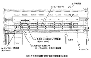
例えば、用紙が図20のような構成であり、印刷装置が図21のような構成の場合では、用紙3の先端から裏面の黒帯プレプリント3x位置中心までの距離は10mmで、テーブル4上に用紙がセットされる時に用紙検出センサ2から用紙3が突き当たるフィードローラ5までの距離Lyも約10mmとなるので、用紙3をフィードローラ5に突き当ててセットすると、裏面の黒帯プレプリント部3xがちょうど用紙検出センサ2上に位置することになる。
For example, when the paper has a configuration as shown in FIG. 20 and the printing apparatus has a configuration as shown in FIG. 21, the distance from the leading edge of the
この場合、裏面の黒帯プレプリント部3xがないときは用紙3による反射光により用紙有りと判定されるが、裏面の黒帯プレプリント部3xがあるときはこれに光が吸収され用紙3からの反射光がなく、用紙無しと判定される。
In this case, when there is no black belt preprint portion 3x on the back surface, it is determined that there is a sheet by reflected light from the
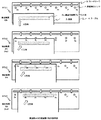
そして、図20の構成の用紙では、裏面の黒帯プレプリント部3xの左右端には35mmずつの余白があり、図21に示したように各用紙検出センサ間距離Lsが48.5mmであるので、前記左右端余白部が用紙検出センサ2上に位置するケースとしては、図22に示したように、ケース(a)のように左右両端の余白に用紙検出センサが位置する場合、ケース(b)のように左右両端のいずれか一方の余白のみに用紙検出センサが位置する場合、ケース(c)のように左右両端のいずれの余白も用紙検出センサが位置しない場合のいずれかとなる。
In the paper having the configuration shown in FIG. 20, there are 35 mm margins on the left and right edges of the black belt preprint portion 3x on the back side, and the distance Ls between the paper detection sensors is 48.5 mm as shown in FIG. Therefore, as the case where the left and right margins are located on the
そして、ケース(a)では、裏面の黒帯プレプリント部3xにより用紙検出センサ2b〜2dにて用紙無しと誤検出するが、左右の用紙検出センサ2a、2eにより2個用紙有りを検出するので、スキューなしと判断し吸入動作を行うことができる。
In the case (a), the black belt preprint unit 3x on the back side erroneously detects that there is no paper by the
しかしながら、ケース(b)では、用紙検出センサ2eだけが用紙有りを検出し、同図(b)の一点鎖線で示したように用紙3が斜めにセットされた場合と同じ検出結果となるので、オペレータが水平にセットした場合であっても、スキューがあると判定され、スキュー補正できない程度に斜めにセットされた状態であると判断され、用紙セットアラームとなり、再度、用紙3のセットをし直さなければならないという問題があった。
However, in case (b), only the
また、ケース(c)では、裏面の黒帯プレプリント部3xにより用紙検出センサ2b〜2eにて用紙無しと誤検出されるので、オペレータが用紙3を正しくセットした場合であっても、用紙3が抜き取られたと判定されて吸入を開始できないという問題点もあった。
In the case (c), the
本発明は、前述の課題を解決するため次の構成を採用する。すなわち、印刷媒体突き当て位置より手前の搬送路上に印刷媒体搬送方向と直角方向に複数の反射型の印刷媒体検出センサを配置し、前記印刷媒体検出センサの検出結果に基づき、挿入される印刷媒体のセット状態を検出する印刷装置において、前記印刷媒体は、黒帯領域を有する印刷媒体であって、前記印刷媒体検出センサが最初に印刷媒体ありを検出した時に前記印刷媒体検出センサが印刷媒体有りを検出した第1の検出個数と、前記最初の検出から所定時間経過後に前記印刷媒体検出センサが印刷媒体有りを検出した第2の検出個数に基づいて前記印刷媒体のスキュー判定を行うスキュー判定手段を設け、前記スキュー判定手段は、前記第2の検出個数が1個以上で前記第1の検出個数以下であったときで、前記第1の検出個数が所定の検出個数以上のときは、前記印刷媒体のスキューなしと判定するようにした。 The present invention employs the following configuration in order to solve the above-described problems. That is, a plurality of reflection type print medium detection sensors are arranged in a direction perpendicular to the print medium conveyance direction on the conveyance path in front of the print medium abutment position , and the print medium to be inserted based on the detection result of the print medium detection sensor the printing apparatus for detecting the set state of the print medium is a print medium having a black band region, the printing medium detecting sensor print medium chromatic when the printing medium detecting sensor has detected the first printing medium a first detection number that detected the Ri, skew performing skew determination of the first of the printing medium detecting sensor after a predetermined time has elapsed from the detection the second detection number to based have been the printing medium detected the presence of the print medium the determination means is provided, said skew determining means, when the second detection number is less than or equal to said first number of detected by one or more, the first detection number is given When the above detection number was possible to determine that there is no skew of the print medium.
本発明の印刷装置によれば、以上のように構成したので、裏面に黒帯プレプリント部を有する用紙であっても、黒帯プレプリントによるスキューの誤検出を防止することができる。 According to the printing apparatus of the present invention, since it is configured as described above, it is possible to prevent erroneous detection of skew due to black band preprinting even on a sheet having a black band preprinted part on the back surface.
以下、本発明に係わる実施の形態例を、図面を用いて説明する。図面に共通する要素には同一の符号を付す。なお、実施例1の用紙および印刷装置の外形的構成は図21の背景技術にて説明したものと同様であるので、簡略化のためにその詳細な説明は省略する。 Embodiments of the present invention will be described below with reference to the drawings. Elements common to the drawings are given the same reference numerals. The external configuration of the paper and the printing apparatus according to the first exemplary embodiment is the same as that described in the background art of FIG. 21, and thus detailed description thereof is omitted for simplification.
(制御系の構成)
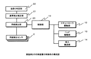
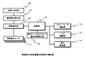
実施例1の印刷装置の制御系の構成は、図1に示したように、テーブル4に用紙3がセットされたかどうかの検出を行う用紙検出センサ2と、スキュー判定手段としての、用紙検出センサ2の検出結果により用紙3の挿入および搬送状態の検出を行う用紙検出部20と、用紙検出センサ2の検出結果の履歴から用紙3の裏面の黒帯プレプリント部3xによるスキューの誤検出を補正する黒帯検出補正部21とを有する。
(Control system configuration)
As shown in FIG. 1, the configuration of the control system of the printing apparatus according to the first embodiment includes a
そして、図示しないスキュー取りローラを回転させ用紙3をフィードローラ5に突き当ててスキューを補正するスキューローラ駆動部12と、図示しない印字ヘッドまたはキャリッジを用紙搬送方向と垂直方向に駆動するヘッド駆動部13と、用紙3の吸入および搬送制御を行う吸入搬送部14と、これらを制御する制御部10とからなる。
Then, a skew
(動作)
以上の構成により、実施例1の印刷装置は以下のように動作する。この動作を図2の動作説明図および図3のタイムチャート図を用いて以下詳細に説明する。
(Operation)
With the above configuration, the printing apparatus according to the first exemplary embodiment operates as follows. This operation will be described in detail below with reference to the operation explanatory diagram of FIG. 2 and the time chart of FIG.
まず、ステップST1は、オペレータが用紙3をセット開始した時の状態を示すもので、このときは用紙3が2a〜2gのいずれの用紙検出センサにも到達していないので、2a〜2gのいずれの用紙検出センサも用紙無しの検出結果となる。
First, step ST1 is intended to indicate a state when the operator has started loading
そして、オペレータが用紙3を押し込むとステップST2のような状態となり、用紙3の先端が2b〜2eの用紙検出センサ上にかかり、2b〜2eの用紙検出センサが用紙無しから用紙有り検出状態に変化する。
Then, when the operator pushes in the
さらに、用紙3が押し込まれるとステップST3のような状態となるが、2b〜2eの用紙検出センサの状態には変化がない。
Further, when the
さらに、用紙3が押し込まれると、ステップST4のような状態となるが、用紙3の裏面の黒帯プレプリント部3xが、2b〜2dの用紙検出センサ上にかかり、2b〜2dの用紙検出センサが用紙有りから用紙無し検出状態に変化する。このとき、用紙検出センサ2eは、裏面の黒帯プレプリント部3xの右端余白部にかかるため、用紙検出センサ2eに変化は発生しない。
Further, when the
さらに、用紙3が押し込まれると、ステップST5のような状態となり、用紙3の先端がフィードローラ5に突き当たった状態となるが、2b〜2eの用紙検出センサの状態には変化がない。
Further, when the
以上の結果、図3に示したように、用紙検出センサ(2a、2f、2g)は、用紙無しのままとして検出され、ステップST2で、2b〜2eの用紙検出センサが用紙無しから用紙有りに切替わり、ステップST4で、2b〜2dの用紙検出センサが用紙有りから用紙無しに切替わり、用紙検出センサ(2e)はそのまま用紙有りが検出される。
As a result of the above, as shown in FIG. 3, the paper detection sensors (2a, 2f, 2g) are detected as being out of paper, and the
なお、これらの用紙検出センサ(2a〜2g)の検出タイミングは、オペレータの操作速度から20ms程度の間隔とすればよい。 The detection timing of these paper detection sensors (2a to 2g) may be set at an interval of about 20 ms from the operation speed of the operator.
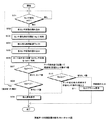
次に、黒帯検出補正部21によりスキューの誤検出を補正する動作を図4の動作フローチャート図を用いて説明する。
Next, the operation of correcting the erroneous detection of skew by the black band
まず、用紙検出部20にて用紙検出センサ(2a〜2g)の検出結果に変化があるかどうかを判定し(ステップS01)、変化があったときは、用紙検出センサ(2a〜2g)の検出結果を読み込み(ステップS02)、この時の検出結果をレジスタStpに格納する(ステップS03)。 First, it is determined whether or not the detection result of the paper detection sensors (2a to 2g) is changed by the paper detection unit 20 (step S01). If there is a change, the detection of the paper detection sensors (2a to 2g) is detected. The result is read (step S02), and the detection result at this time is stored in the register Stp (step S03).
次に、前記用紙検出センサ(2a〜2g)の変化を検出した時から用紙3の吸入を開始するまでの所定の時間Tx、すなわちオペレータが用紙3をテーブル4にセットしてからフィードローラ5に突き当てるまでの吸入待ち時間(例えば、500msec程度)、ウェイトする(ステップS04)。
Next, a predetermined time Tx from when the change of the sheet detection sensors (2a to 2g) is detected to when the
そして、前記吸入待ち時間Tx経過後に、用紙検出センサ(2a〜2g)の検出結果を読み込み(ステップS05)、用紙3がフィードローラ5に突き当たっている位置での用紙検出センサ(2a〜2g)の結果としてレジスタSedに格納する(ステップS06)。
Then, after the suction waiting time Tx has elapsed, the detection results of the paper detection sensors (2a to 2g) are read (step S05), and the paper detection sensors (2a to 2g) at the position where the
ここで、レジスタSedの値が0の場合、すなわち用紙有りを検出したセンサ数が0の場合は、ステップS01にて、一旦用紙検出センサ(2a〜2g)の位置まで用紙3を挿入したが、その後、抜き取ったものと判断し、ステップS01に戻り、再度用紙3がセットされるのを待つ(ステップS07・ステップS08)。
Here, if the value of the register Sed is 0, that is, if the number of sensors that detected the presence of paper is 0, the
用紙有りを検出したセンサ数であるレジスタSedの値が0または1以外の場合は、制御部10より吸入搬送部14に吸入開始要求を行い(ステップS09)、ヘッド駆動部13にて図示しない印字ヘッドを印字位置に移動させ、印字を行う。
If the value of the register Sed, which is the number of sensors that detected the presence of paper, is other than 0 or 1, the
一方、ステップS07にて、吸入待ち時間Tx経過後の用紙有りを検出したセンサ数であるレジスタSedの値が1の場合は、最初に用紙検出センサが変化した時の用紙ありセンサの数であるレジスタStpの値を参照して2以上かどうかを判定し(ステップS10)、レジスタStpの値が1以下の場合は、オペレータが用紙3を、スキューを補正できない程度に斜めにセットした場合であるので、セットアラームを要求する(ステップS11)。
On the other hand, if the value of the register Sed, which is the number of sensors that have detected the presence of paper after the elapse of the suction waiting time Tx in step S07, is 1, this is the number of sensors with paper when the paper detection sensor first changes. It is determined whether or not the value is 2 or more by referring to the value of the register Stp (step S10). If the value of the register Stp is 1 or less, the operator has set the
一方、レジスタStpの値が2以上の場合は、用紙3の先端を2個以上の用紙検出センサで検出した場合であるので、用紙2を正常にセットしたが、吸入待ち時間Tx経過後に用紙3の裏面の黒帯プレプリント部3xが用紙検出センサ2上にかかった状態であると判定し、黒帯検出補正部21にてスキューの誤検出を補正し、ステップS09に進んで用紙3の吸入を開始する。
On the other hand, when the value of the register Stp is 2 or more, the leading edge of the
なお、以上のステップS02〜ステップS04の説明では、用紙3の先端が水平に挿入セットされた場合を例として説明したが、用紙3がやや斜めにセットされた場合や用紙先端が乱れている場合では、用紙検出センサ(2b〜2d)の用紙無しから用紙有りを検出するタイミングが図3の破線a部のように乱れる場合があるので、これを考慮してステップS02において5ms程度の間隔で用紙検出センサ(2b〜2d)の出力を数回読み込み、平滑化等した結果をレジスタStpに格納するようにするとよい。
In the above description of steps S02 to S04, the case where the front end of the
(実施例1の変形例の動作)
また、以上の説明では、レジスタStp、Sedの値によりステップS07〜S11のようにスキューの誤検出を防止するように説明したが、図5のステップS27〜S31に示したように、スキューの誤検出を防止するようにしてもよい。
(Operation of Modified Example of Embodiment 1)
In the above description, it has been described that the erroneous detection of the skew is prevented as in steps S07 to S11 by the values of the registers Stp and Sed. However, as shown in steps S27 to S31 of FIG. Detection may be prevented.
すなわち、まず、実施例1の動作と同様にステップS21〜S26にて用紙検出センサ(2a〜2g)の検出結果に変化があったときにその数をレジスタStpに格納し、フィードローラ5に突き当てた位置として、吸入待ち時間Tx経過後の用紙有りのセンサ数をレジスタSedに格納する(ステップS21〜S26)。
That is, first, similarly to the operation of the first embodiment, when the detection results of the sheet detection sensors (2a to 2g) are changed in steps S21 to S26, the number is stored in the register Stp and pushed to the
そして、フィードローラ突き当て位置での用紙有りのセンサ数であるレジスタSedの値が、用紙セット時の用紙有り検出の数であるレジスタStpの値以下で、1以上であるかどうかを判定し(ステップS27)、当該条件に該当しない場合は、裏面の黒帯プレプリント部3xのない用紙3が、少し斜めにセットされた場合か抜き取られた場合であると判定し、次に、レジスタSedが0かどうかを判定し(ステップS28)、0の場合は、用紙3をセットした後、用紙3を抜き取ったとして、ステップS21に戻る。
Then, it is determined whether or not the value of the register Sed, which is the number of sensors with paper at the feed roller abutting position, is equal to or larger than 1 with the value of the register Stp being the number of paper presence detected when the paper is set ( In step S27), if the condition is not met, it is determined that the
一方、レジスタStpの値よりレジスタSedの方が小さいときは、裏面の黒帯プレプリント部3xによる検出があったとしてステップS30に進み、レジスタStpが所定の値α以上かどうかを判定し、α以上であった場合は、裏面の黒帯プレプリント部3xによる誤検出があったとして通常の吸入動作を開始する。 On the other hand, when the value of the register Sed is smaller than the value of the register Stp, it is determined that there is a detection by the black band preprint unit 3x on the back surface, and the process proceeds to step S30, where it is determined whether the register Stp is equal to or greater than a predetermined value α. In the case above, the normal suction operation is started on the assumption that there is an erroneous detection by the black belt preprint unit 3x on the back surface.
ステップS30にて、レジスタStp値がαより小さかった場合は、斜めに用紙3をセットした場合であると判断してセットアラームを要求する(ステップS31)。
If the register Stp value is smaller than α in step S30, it is determined that the
以上のようにすることにより、用紙3の裏面の黒帯プレプリント部3xの特に横方向の幅や余白部分の幅が変化しても、スキューの誤検出を防止することができる。
By doing as described above, even if the width of the black band preprint portion 3x on the back surface of the
(実施例1の効果)
以上詳細に述べたように、実施例1の印刷装置によれば、用紙検出センサの検出結果の履歴から用紙3の裏面の黒帯プレプリント部によるスキューの誤検出を補正する黒帯検出補正部を設け、フィードローラへの突き当て位置における用紙有りを検出した個数が1個の場合で、最初に用紙検出センサの変化時の用紙ありの個数が2以上の場合、或いはフィードローラへの突き当て位置における用紙有りを検出した個数が1個以上で最初に用紙検出センサの変化時の用紙ありの個数より少ない場合で、かつ用紙検出センサの変化時の用紙ありの個数が所定の数以上であったときはスキューなしと判断して吸入動作を行うようにしたので、裏面に黒帯プレプリント部を有する用紙であっても、黒帯プレプリントによるスキューの誤検出を防止することができる。
(Effect of Example 1)
As described in detail above, according to the printing apparatus of the first embodiment, the black band detection correction unit that corrects erroneous detection of skew by the black band preprint unit on the back surface of the
(制御系の構成)
実施例2の印刷装置1の制御系の構成は、図6に示すように、一旦セットされた裏面の黒帯プレプリント部3xの左右端に余白のない用紙3が抜取られたか否かを判定する抜取り判定部22を新たに設けている。その他の構成は実施例1の構成と同様であるので、その詳細な説明を省略する。
(Control system configuration)
As shown in FIG. 6, the control system configuration of the
(動作)
以上の構成により、実施例2の印刷装置1は以下のように動作する。本動作を、図7および図9の動作説明図および図8の履歴バッファのデータ例を用いて、以下詳細に説明する。
(Operation)
With the above configuration, the
(用紙がセットの途中で抜き取られた場合) (When paper is pulled out during loading)
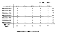
最初に、オペレータが用紙3のセットを完了する前に途中で抜き取った場合の動作を図7の動作説明図および図8の履歴バッファのデータ例を用いて説明する。まず、図7に示したように、ステップST11は、オペレータが用紙3を左肩上がりの状態にセット開始した時の状態を示すもので、このときは用紙3が2a〜2gいずれの用紙検出センサにも到達していないので、2a〜2gいずれの用紙検出センサも用紙無しの検出結果となり、履歴バッファ格納値も00hの用紙無し状態となる。
First, the operation when the operator pulls out the
なお、前記履歴バッファ格納値は、用紙なしを"0"、用紙ありを"1"とし、また、用紙検出センサ2a側を最下位ビットbit0とし、用紙検出センサ2gを上位の第2ビットbit6とし、最上位ビットbit7は一律"0"として、16進にて表記したものである。
The history buffer storage values are “0” when there is no paper, “1” when there is paper, the least significant bit bit0 on the
そして、オペレータが矢印A方向に用紙3を押し込むとステップST12のような状態となり、用紙3の先端が用紙検出センサ(2bおよび2c)上にかかり、用紙検出センサ(2bおよび2c)が用紙無しから用紙有り検出状態に変化し、bit1、bit2が"1"となるので、履歴バッファ格納値は06hとなる。
Then, when the operator pushes the
さらに、用紙3が押し込まれると、ステップST13のような状態となり、用紙3の先端が用紙検出センサ(2d)上にもかかり、用紙検出センサ(2d)も用紙有り検出状態に変化し、bit1、bit2に加えbit3も"1"となるので、履歴バッファ格納値は0Ehとなる。
Further, when the
この状態からオペレータが矢印B方向に用紙3を抜取り始めると、ステップST14のような状態となり、用紙3の先端が用紙検出センサ(2d)から外れ、用紙検出センサ(2d)が用紙無し検出状態に変化し、bit3が"0"となるので、履歴バッファ格納値は06hとなる。
When the operator starts to pull out the
この状態から、さらにオペレータが用紙3を抜きると、ステップST15のような状態となり、用紙3の先端が用紙検出センサ(2bおよび2c)から外れ、用紙検出センサ(2bおよび2c)が用紙無し検出状態に変化し、bit1、bit2が"0"となるので、履歴バッファ格納値は00hとなる。
If the operator further pulls out the
(用紙が抜き取られない場合)
次に、オペレータが用紙3をセットし、抜き取らなかった場合について、図9の動作説明図および図10の履歴バッファのデータ例を用いて説明する。
(When paper cannot be removed)
Next, the case where the operator sets the
オペレータが用紙3を左肩上がりの状態でセットし矢印A方向に押し込むと、用紙検出センサ(2bおよび2c)が用紙無しの状態から用紙有りの状態に変化し、bit1、bit2が"1"となり、履歴バッファ格納値は06hとなり、さらに、矢印A方向に押し込むと、用紙検出センサ(2d)も用紙有りの状態に変化し、bit3が"1"となり、履歴バッファ格納値は0Ehとなる。(ステップST11〜ステップST13)。
When the operator sets the
そして、ステップST13の状態からオペレータがさらに用紙3を押し込むと、ステップST14fの状態となり、裏面の黒帯プレプリント部3xが用紙検出センサ(2bおよび2c)上にかかり、用紙検出センサ(2bおよび2c)が用紙有り検出状態から用紙無し検出状態に変化し、用紙検出センサ(2d)は用紙有り検出状態のままであるので、bit1、bit2が"0"となり、履歴バッファ格納値は08hとなる。
When the operator further presses the
そして、オペレータがさらに用紙3を押し込むと、ステップST15fの状態となり、裏面の黒帯プレプリント部3xが用紙検出センサ(2d)上にもかかり、用紙検出センサ(2d)が用紙有り検出状態から用紙無し検出状態に変化し、bit3も"0"となり、履歴バッファ格納値は00hとなる。
When the operator further presses the
以上のように、オペレータが用紙3を抜き取った場合、用紙3を抜き取らなかった場合と比較すると、抜き取った場合では、ステップST14にて履歴バッファ格納値は06hであったのに対し、抜き取らなかった場合ではステップST14fにて履歴バッファ格納値は08hとなっていることがわかる。その他のステップでの履歴バッファ格納値は同じようになっている。
As described above, when the operator pulled out the
(抜取り判定処理)
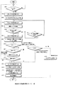
次に、用紙3がセットの途中で抜取られたか否かを抜取り判定部22によって判断する動作を図11の動作フローチャート図を用いて説明する。
(Sampling judgment process)
Next, an operation of determining whether or not the
まず、用紙検出部20にて用紙検出センサ(2a〜2g)のいずれかの検出結果に変化があるかどうかを判定し(ステップS41)、変化があったときは、用紙検出センサ(2a〜2g)の検出結果を読み込み(ステップS42)、変化後の検出結果をレジスタStpに格納する(ステップS43)。
First, the
そして、用紙検出センサ(2a〜2g)の状態を読み込み(ステップS44)、履歴バッファに格納する(ステップS45)。 The state of the paper detection sensors (2a to 2g) is read (step S44) and stored in the history buffer (step S45).
ここで、吸入待ち時間、すなわち用紙検出センサ(2a〜2g)の変化を検出した時から用紙3の吸入を開始するまでの所定の時間Txが経過したかどうかを判断する(ステップS46)。吸入待ち時間Txが経過していないときは、センサ検出タイミングの時間が経過しているかを判定し(ステップS47)、センサ検出タイミングの時間が経過したときにステップS44に戻り、ステップS45、S46の動作を繰り返す。
Here, it is determined whether or not a predetermined time Tx from when the suction waiting time, that is, the change of the paper detection sensors (2a to 2g) is detected until the suction of the
そして、前記吸入待ち時間Tx経過後、すなわち、用紙3をフィードローラ5に突き当てた位置での用紙検出センサ(2a〜2g)の結果をレジスタSedに格納する(ステップS48・S49)。
Then, after the suction waiting time Tx elapses, that is, the result of the paper detection sensors (2a to 2g) at the position where the
そして、レジスタSedの用紙有り状態センサ数が0の場合、すなわち吸入待ち時間Tx経過後のセンサ状態が全て用紙無しの場合は(ステップS50・S51)、ステップS45にて格納してある履歴バッファ格納値をサーチする(ステップS52)。 If the number of sensors in the register Sed is zero, that is, if all the sensor states after the inhalation waiting time Tx have elapsed (steps S50 and S51), the history buffer stored in step S45 is stored. A value is searched (step S52).
そして、抜取り判定部22にて履歴バッファ格納値の最大値をサーチし、その前後の位置に同じセンサ状態が存在するかどうかを判定し、同じセンサ状態が存在する場合は、用紙検出センサ(2a〜2g)の位置まで用紙3を挿入したが、その後、用紙3を抜き取ったと判定し、ステップS41へ戻り、再度用紙3がセットされるのを待つ(ステップS53)。
Then, the
一方、履歴バッファ格納値の最大値の前後に、同じセンサ状態が存在しない場合は、用紙3を抜き取らずにそのまま押し込み、裏面の黒帯プレプリント部3xが用紙検出センサ2上にかかった場合であると判定し、吸入搬送部14に吸入開始要求を行い(ステップS54)、ヘッド駆動部13にて図示しない印字ヘッドを印字位置に移動させ、印字を行う。
On the other hand, if the same sensor state does not exist before and after the maximum value stored in the history buffer, the
また、レジスタSedの値が1の場合、すなわち、用紙3がフィードローラ5に突き当たった状態における用紙有りを検出したセンサ数が1の場合は、レジスタStpの値を参照して2以上かどうかを判定し(ステップS55)、レジスタStpの値が1以下であれば、用紙3をスキュー補正できない程度に斜めにセットした場合であると判定し、セットアラームを要求する(ステップS56)。
Further, when the value of the register Sed is 1, that is, when the number of sensors that detect the presence of the
一方、レジスタStpの値が2以上、すなわち初めに用紙有りを検出したセンサ数が2以上の場合は、裏面に黒帯プレプリント部3xを有する用紙3が、スキュー補正が可能な程度に斜めにセットされた場合であると判定し、吸入を開始する。
On the other hand, when the value of the register Stp is 2 or more, that is, when the number of sensors that first detected the presence of the sheet is 2 or more, the
すなわち、用紙3の先端を用紙検出センサ(2a〜2g)により検出したときに、用紙有りを検出したセンサ数が2以上であるので、用紙3は正常にセットされており、吸入待ち時間Tx経過後に用紙3の裏面の黒帯プレプリント部3xが用紙検出センサ2上にかかった状態であると判定し、黒帯検出補正部21にてスキューの誤検出を補正しステップS54に進んで用紙3の吸入を開始する。
That is, when the leading edge of the
なお、以上の実施例の説明では、図7、図9のように、左肩上がりの用紙セットについて説明したが、右肩上がりの用紙セットであっても同様であり、履歴バッファ格納値の最大値の前後に、同じセンサ状態が存在するかどうかによって抜取りか否かの判断ができる。 In the above description of the embodiment, the left-up shoulder paper set has been described as shown in FIGS. 7 and 9. However, the same applies to the right-up paper set, and the maximum value stored in the history buffer is the same. Whether or not the sampling is performed can be determined by whether or not the same sensor state exists before and after.
また、以上の実施例の説明では、履歴バッファ格納値の最大値の前後に、同じセンサ状態が存在するかどうかによって抜取りか否かの判断を行うように説明したが、履歴バッファ格納値から用紙有り検出をしたセンサ個数が最大となる位置をサーチし、その前後の位置に同じセンサ状態が存在するかどうかによって抜取りか否かの判断するようにしてもよい。 Further, in the above description of the embodiment, it has been described that whether or not the same sensor state exists before and after the maximum value of the history buffer stored value is determined as to whether or not to extract, the paper is determined from the history buffer stored value. A position where the number of detected sensors is maximized may be searched, and it may be determined whether or not the extraction is performed depending on whether or not the same sensor state exists at the positions before and after that.
さらに、ステップ50、S51、S55の動作については、実施例1の変形例にて説明したように、S27、S28、S30のように所定の値αを基準とした判定とするようにしてもよい。 Further, the operations in steps S50, S51, and S55 may be determined based on the predetermined value α as in S27, S28, and S30 as described in the modification of the first embodiment. .
(実施例2の効果)
以上詳細に述べたように、実施例2の印刷装置によれば、実施例1の構成に加え、履歴のうち最大値を検出した位置の前後に同じセンサ状態が存在するかどうかによって用紙を抜き取ったか否かを判定する抜取り判定部を設けたので、実施例1の効果に加え、用紙裏面の黒帯プレプリント部の影響を受けずに、用紙をセット後に抜き取ったかどうかを正確に判定することができる。
(Effect of Example 2)
As described in detail above, according to the printing apparatus of the second embodiment, in addition to the configuration of the first embodiment, paper is extracted depending on whether or not the same sensor state exists before and after the position where the maximum value is detected in the history. In addition to the effects of the first embodiment, the sampling determination unit that determines whether or not the sheet has been removed can be accurately determined whether or not the sheet has been extracted without being affected by the black belt preprint unit on the back side of the sheet. Can do.
(制御系の構成)
実施例3の印刷装置1の制御系の構成は、図12に示すように、実施例2の構成に第1のヘッドセンタリング基準位置補正部23を新たに設けた構成としている。なお、一般には、ヘッドセンタリング動作は、用紙吸入後に印字ヘッドまたはキャリッジに取り付けられたセンサにより用紙左右端部を検出して、印字ヘッドの書き出し位置を決める動作のことをいうが、便宜上、本実施例においては、用紙吸入前に、印字ヘッドにて用紙端のカールを押さえるための動作のことをヘッドセンタリング動作という。
(Control system configuration)
The configuration of the control system of the
第1のヘッドセンタリング基準位置補正部23は、裏面の黒帯プレプリント部3xの影響により前記ヘッドセンタリングの動作を行う基準位置が適正な位置とならない不具合を解決するために設けたものである。
The first head centering reference
すなわち、例えば、前述の図2に示したような裏面の黒帯プレプリント部3xを有した用紙3をセットして印刷する場合、吸入の直前(ステップST5)に、最左端の用紙あり検出をした用紙検出センサの位置をヘッドセンタリングの基準位置とすると、用紙検出センサ2b〜2dが裏面の黒帯プレプリント部3xにより用紙なしとして検出され、用紙検出センサ2eだけが右端余白により用紙ありを検出するので、用紙検出センサ2eの位置が最左端の用紙あり検出をした用紙検出センサの位置となり、ヘッドセンタリングの基準位置を誤ることになる。
That is, for example, when the
実施例3の第1のヘッドセンタリング基準位置補正部23は、この問題を解決するために、初めにセンサ変化があったときのレジスタStpに格納された検出結果と所定の時間Tx経過後のレジスタSedに格納された検出結果とのORを取り、当該検出結果の最左端に相当する用紙検出センサ2の位置をヘッドセンタリグの基準位置と判定するものである。その他の構成は実施例2の構成と同様であるので、簡略化のためにその詳細な説明を省略する。
In order to solve this problem, the first head centering reference
(動作)
以上の構成により、実施例3の印刷装置は、以下のように動作する。本動作を実施例1にて説明した図2のように用紙を挿入した場合を例として、図13の履歴バッファのデータ例および図14のセンサ結果の論理ORの例示図を用いて以下説明する。
(Operation)
With the above configuration, the printing apparatus according to the third embodiment operates as follows. This operation will be described below with reference to an example of the history buffer data in FIG. 13 and the logical OR of the sensor result in FIG. 14, taking as an example the case where a sheet is inserted as shown in FIG. 2 described in the first embodiment. .
まず、図2のような用紙をセットし挿入した場合、図13に示したように各ステップごとに用紙検出センサの検出結果が得られる。そして、初めにセンサ変化があったときの検出結果をレジスタStpに格納する。本例では、用紙検出センサ(2b〜2e)が用紙有りとなるので、レジスタStpの値は1Ehとなる(ステップST2)。 First, when the paper as shown in FIG. 2 is set and inserted, the detection result of the paper detection sensor is obtained for each step as shown in FIG. Then, the detection result when the sensor is changed first is stored in the register Stp. In this example, since the paper detection sensors (2b to 2e) have paper, the value of the register Stp is 1Eh (step ST2).
そして、吸入待ち時間Tx経過後の、オペレータがフィードローラ5の位置まで用紙3を突き当てて挿入した時のセンサ検出結果では、用紙検出センサ(2e)だけが用紙有りとなり、レジスタSedの値は10hとなる(ステップST5)。
Then, after the suction waiting time Tx has elapsed, when the operator detects and inserts the
そして、第1のヘッドセンタリング基準位置補正部23にて、初めにセンサ変化があったときの用紙検出センサの結果であるレジスタStp値と、吸入待ち時間Tx経過後の(吸入起動直前の)用紙検出センサの結果であるレジスタSed値との論理ORを求め、レジスタSorに格納する。本例では、レジスタStp値は1Ehであり、レジスタSed値が10hであるので、レジスタSorの値は1Ehとなる。
Then, in the first head centering reference
そして、レジスタSorの最下位ビットのbit0(すなわち、最左端の用紙検出センサ2aの検出結果)から、bit1、bit2、bit3と順にbit情報が1となっているbitを検出し、当該bitを用紙左端位置に相当する用紙検出センサの位置であると判定する。
Then, from the
本例では、bit1(用紙検出センサ2b)が最初に1となる用紙検出センサであるので、当該用紙検出センサ(2b)の位置がヘッドセンタリング位置の基準位置と判定する。
In this example, since bit1 (
次に、図15の動作フロー図を用いて実施例3の動作を詳細に説明する。まず、用紙検出部20にて用紙検出センサ(2a〜2g)の検出結果に変化があったときは、用紙検出センサ(2a〜2g)の検出結果を読み込み、変化時の検出結果をレジスタStpに格納する(ステップS61〜ステップS63)。
Next, the operation of the third embodiment will be described in detail with reference to the operation flowchart of FIG. First, when there is a change in the detection results of the paper detection sensors (2a to 2g) in the
そして、用紙検出センサ(2a〜2g)の状態を読み込み、履歴バッファに格納する(ステップS64・ステップS65)。 Then, the state of the paper detection sensors (2a to 2g) is read and stored in the history buffer (steps S64 and S65).
ここで、吸入待ち時間、すなわち用紙検出センサ(2a〜2g)の変化を検出した時から用紙3の吸入を開始するまでの吸入待ち時間Txが経過したかどうかを判断する(ステップS66)。吸入待ち時間Txが経過していないときは、センサ検出タイミングの時間が経過しているか判断し(ステップS67)、センサ検出タイミングの時間が経過した場合ステップS64およびステップS65の動作を繰り返す。
Here, it is determined whether or not the suction waiting time Tx from the time when the suction waiting time, that is, the change of the paper detection sensors (2a to 2g) is detected to the time when the suction of the
そして、吸入待ち時間Tx経過後、用紙検出センサ(2a〜2g)の検出結果を読み込み(ステップS68)、用紙3をフィードローラ5に突き当てた位置での用紙検出センサ(2a〜2g)の結果をレジスタSedに格納する(ステップS69)。
Then, after the suction waiting time Tx elapses, the detection result of the paper detection sensors (2a to 2g) is read (step S68), and the result of the paper detection sensor (2a to 2g) at the position where the
ここで、レジスタSedの値が1の場合、すなわち、用紙3をフィードローラ5に突き当てた位置での用紙有りを検出したセンサ数が1の場合は(ステップS70)、レジスタStpの値を参照して2以上かどうかを判定する(ステップS78)。
Here, when the value of the register Sed is 1, that is, when the number of sensors that detect the presence of paper at the position where the
レジスタStpの値が2以上、すなわち初めに用紙有りを検出したセンサ数が2以上であれば、用紙3の先端を用紙検出センサ2により検出したときは用紙有りを検出したセンサ数が2以上であるので、用紙3は正常にセットしており、吸入待ち時間Tx経過後に用紙3の裏面の黒帯プレプリント部3xが用紙検出センサ2上にかかった状態であると判定し、吸入開始要求を行う前に第1のヘッドセンタリング基準位置補正部にて、以下のセンサ情報判定処理を行い、正しいヘッドセンタリグ位置の基準を求める。
If the value of the register Stp is 2 or more, that is, the number of sensors that first detected the presence of paper is 2 or more, when the leading edge of the
すなわち、レジスタStpのbit情報とレジスタSedのbit情報を論理OR演算し、レジスタSorに格納する(ステップS74)。図2の例では、前述のように、論理ORの結果は1EhとなるのでレジスタSorに1Ehを格納する。 That is, the bit information of the register Stp and the bit information of the register Sed are logically ORed and stored in the register Sor (step S74). In the example of FIG. 2, as described above, since the result of the logical OR is 1Eh, 1Eh is stored in the register Sor.
そして、レジスタSor値である1Ehの最下位のbit0から、bit情報が0から1となる最初のbitを検索する(ステップS75)。この検索結果から最左端の用紙検出センサ2を判定して当該用紙検出センサ2の位置をヘッドセンタリング位置の基準とする(ステップS76)。
Then, the first bit in which the bit information is 0 to 1 is searched from the
そして、前記センサ情報判定処理にて求めたヘッドセンタリングの基準位置に基づき、印字ヘッドのセンタリングを行い、吸入搬送部14に吸入開始要求を行う(ステップS77)。 Then, based on the head centering reference position obtained in the sensor information determination process, the print head is centered, and a suction start request is sent to the suction transport unit 14 (step S77).
一方、レジスタStpの値が1以下の場合は、オペレータがスキューを補正できない程度に用紙3を斜めにセットした場合であるので、スキュー補正できないと判定し、セットアラームを要求する(ステップS79)。
On the other hand, when the value of the register Stp is 1 or less, it is a case where the
また、レジスタSedの用紙有り状態センサ数が0の場合、すなわち、用紙3をフィードローラ5に突き当てた位置での用紙有りを検出したセンサ数が0の場合は、ステップS65にて格納してある履歴バッファ格納値をサーチする(ステップS70〜ステップS72)。
If the number of sensors in the register Sed is 0, that is, if the number of sensors that detect the presence of paper at the position where the
そして、抜取り判定部22にて、履歴バッファ格納値の最大値の前後に同じセンサ状態が出現する場合は、一旦用紙検出センサ2まで用紙3を挿入したが、その後、抜き取られたと判断し、ステップS61に戻り、用紙3が挿入されるのを待つ。
If the same sensor state appears before and after the maximum value stored in the history buffer in the
一方、履歴バッファ格納値の最大値の前後に同じセンサ状態が出現しない場合は、裏面の黒帯プレプリント部3xが、用紙検出センサ2上にかかった状態であると判断し、前述したセンサ情報判定処理を行いヘッドのセンタリングを行った後(ステップS74〜S76)、吸入搬送部14に吸入開始要求を行う(ステップS77)。
On the other hand, if the same sensor state does not appear before and after the maximum value stored in the history buffer, it is determined that the black belt preprint unit 3x on the back surface is on the
また、レジスタSedの値が0または1以外の場合、すなわち、用紙有りを検出したセンサ数が0または1以外の場合は、裏面の黒帯プレプリント3xが無い通常の用紙であるので、前述したセンサ情報判定処理を行いヘッドのセンタリングを行った後(ステップS74〜S76)、吸入搬送部14に吸入開始要求を行う(ステップS77)。 In addition, when the value of the register Sed is other than 0 or 1, that is, when the number of sensors that detect the presence of the sheet is other than 0 or 1, it is a normal sheet without the black belt preprint 3x on the back surface, and thus the above-described case. After performing the sensor information determination process and performing the centering of the head (steps S74 to S76), a suction start request is sent to the suction conveyance unit 14 (step S77).
なお、以上の説明では、レジスタSor値の最下位のbit0から、bit情報が0から1となる最初のbitを検索し、そのbitに対応する用紙検出センサ2の位置をヘッドセンタリング位置の基準とするように説明したが、bit情報が、さらに0に変化するbitを検索し、そのbitに対応する用紙検出センサ2の位置を用紙の右端位置として、これらの位置情報から用紙の中央位置を算出しヘッドセンタリング位置とするようにしてもよい。
In the above description, the first bit where the bit information is 0 to 1 is searched from the
(実施例3の効果)
以上詳細に述べたように、実施例3の印刷装置によれば、用紙の先端部を検出した用紙検出センサの検出結果と、所定の時間経過後の用紙検出センサの検出結果の論理和を求め、当該論理和に基づき最左端のセンサを決定する第1のヘッドセンタリング基準位置補正部を設けたので、裏面に黒帯プレプリント部を有する用紙においてもヘッドセンタリングの基準位置の誤検出を防止することができる。
(Effect of Example 3)
As described above in detail, according to the printing apparatus of the third embodiment, the logical sum of the detection result of the paper detection sensor that detects the leading edge of the paper and the detection result of the paper detection sensor after a predetermined time has elapsed is obtained. Since the first head centering reference position correction unit that determines the leftmost sensor based on the logical sum is provided, erroneous detection of the reference position of the head centering is prevented even in the paper having the black belt preprint part on the back surface. be able to.
(制御系の構成)
実施例4の印刷装置1の制御系の構成は、図16に示すように、実施例3の第1のヘッドセンタリング基準位置補正部23の代わりに、第2のヘッドセンタリング基準位置補正部24を設けた構成としている。第2のヘッドセンタリング基準位置補正部24は、初めに用紙検出センサ2にて用紙先端を検出した時点から、吸入待ち時間Txが経過してフィードローラ5に突き当てる時点までの間に、横方向に用紙3をずらしながら挿入した場合に、ヘッドセンタリングの基準位置が適正とならない不具合を解決するために設けたものである。
(Control system configuration)
As shown in FIG. 16, the control system of the
すなわち、第2のヘッドセンタリング基準位置補正部24は、フィードローラ5に用紙3を突き当てた時に用紙ありとして検出した用紙検出センサの位置が、用紙セット可能範囲の中央より左右何れの領域にあるかを判断し、右側の領域にある用紙検出センサの場合は、当該用紙検出センサの位置から略用紙幅だけ左に位置する用紙検出センサをヘッドセンタリングの基準位置とするように補正を行うものである。その他の構成は実施例3の構成と同様であるので、その詳細な説明を省略する。
That is, the second head centering reference
(動作)
以上の構成により実施例4の印刷装置1は、以下のように動作する。本動作を図17の動作説明図および図18の動作フローチャート、図19の用紙セット範囲の説明図を用いて以下詳細に説明する。
(Operation)
With the above configuration, the
図17は、裏面に黒帯プレプリント部3xを有した用紙3を横滑り(斜め移動)させながら押し込んだときの用紙の遷移を示した図である。まず、ステップST21は、用紙3をセットしたときの状態である。
FIG. 17 is a diagram showing the transition of the paper when the
ステップST22は、用紙セットの過程で、用紙先端が用紙検出センサ2a〜2d上にかかった状態である。この状態から、オペレータは、さらに、右上方向に移動させながら用紙を押し込む。
Step ST22 is a state in which the leading edge of the sheet is placed on the
すると、ステップST23のように、用紙3が用紙検出センサ2a〜2dに加え、用紙検出センサ2e上にもかかった状態となる。また、斜めに移動させたため、用紙3の左端が用紙検出センサ2aから外れかかっている。この状態から、オペレータは、さらに、斜め移動させながら用紙を押し込む。
Then, as in step ST23, the
すると、ステップST24のように、オペレータがフィードローラ5位置まで用紙を突き当て、物理的に用紙が用紙検出センサ2b〜2e上にかかった状態となる。用紙3の左端は、用紙検出センサ2aから外れている。このとき、裏面に黒帯プレプリント部3xがあるので、用紙有りとして検出される用紙検出センサは、2eだけとなる。
Then, as in step ST24, the operator hits the sheet up to the position of the
この場合、実施例3の第1のヘッドセンタリング基準位置補正部23による処理を行うと、ステップST22にて検出結果(0Fh)をレジスタStpに格納し、ステップST24にて検出結果(1Eh)をレジスタSedに格納することになるので、論理ORした結果では1Fhとなり、本来、用紙検出センサ2bが基準となるべきところが、用紙検出センサ2aがヘッドセンタリング位置の基準となってしまい適正位置とならない。
In this case, when the processing by the first head centering reference
この不具合を解決するために設けた第2のヘッドセンタリング基準位置補正部24の動作について、図18の動作フローチャートに従い、図19の動作説明図を用いて詳細に説明する。なお、本例では、図19のように、用紙幅は203mmで、黒帯の幅が133mm、余白の長さが35mmであり、用紙検出センサの間隔が48.5mmにて設けられている一例として説明する。
The operation of the second head centering reference
まず、図19のケースAとケースBの間の用紙セットの場合では、用紙検出センサ2b、2eの2つのセンサが用紙有りを検出するので、図18のステップS80の判定によりステップS86に移動し、実施例3と同様のヘッドセンタリング基準位置補正を行い、紙有りを検出している最左端の用紙検出センサ、すなわち用紙検出センサ2bの位置をヘッドセンタリングの基準位置として決定する。
First, in the case of the paper set between case A and case B in FIG. 19, since the two sensors,
同様に、図19のケースCとケースDの間の用紙セットの場合では、用紙検出センサ2a、2eの2つのセンサが用紙有りを検出するので、ステップS80の判定によりステップS86に移動し、実施例3と同様のヘッドセンタリング基準位置補正を行い、紙有りを検出している最左端の用紙検出センサ、すなわち用紙検出センサ2aの位置をヘッドセンタリングの基準位置として決定する。
Similarly, in the case of the paper set between case C and case D in FIG. 19, since the two sensors, the
そして、ケースBからケースCの間のケースBの2のような用紙セットの場合では、用紙検出センサ2eのみが用紙ありとして検出されるので、用紙有り検出センサ数が1の場合は、ステップS81に進み、ステップS81およびS82にて、黒帯プレプリント部3xの左右いずれの余白位置にて用紙有り検出があったかどうかを判定する。
In the case of a paper set such as
ここで、黒帯プレプリント部3xの右端余白で用紙有りを検出できる用紙検出センサは、用紙検出センサ2d、2e、2f、2gであり、用紙検出センサ2a、2b、2cでは、右端余白で用紙有りを検出できない。
Here, the
従って、用紙有りの用紙検出センサ数が1の場合で、且つ、用紙有り検出が用紙検出センサ2a、2b、2cのいずれかであれば、黒帯プレプリント部3xの左端余白で検出したものと判断でき、ステップ85にて当該用紙検出センサの位置をヘッドセンタリングの基準位置として決定する。
Therefore, if the number of paper detection sensors is 1 and the paper detection is one of the
一方、用紙有り状態センサ数が1の場合で、且つ、用紙有り検出が用紙検出センサ2e、2f、2gのいずれかであれば、黒帯プレプリント部3xの右端余白3bで検出したものと判断できる。この場合は、以下に説明する計算により最左端に該当する用紙検出センサを推定し、当該用紙検出センサの位置をヘッドセンタリングの基準位置として決定する(ステップS83およびS84)。
On the other hand, if the number of paper presence sensors is 1 and the paper presence detection is one of the
すなわち、黒帯プレプリント部(幅C)と、黒帯プレプリント部の左端余白(幅L)を加えた長さL+Cは168mmであるので、センサ間の距離ΔLsである48.5mmをn(整数)倍して、前記L+Cの長さ168mmと比較する。 That is, since the length L + C including the black belt preprint portion (width C) and the left end margin (width L) of the black belt preprint portion is 168 mm, 48.5 mm which is the distance ΔLs between the sensors is n ( It is multiplied by an integer) and compared with the L + C length of 168 mm.
そして、L+C<48.5×nとなる最少のnの値を求め、用紙有り状態を右端余白3bで検出した検出センサの番号(この場合は、用紙検出センサ2eであるので左から5番目)の情報に基づき、最左端にかかっている求めるべき用紙検出センサを求める。
Then, the minimum value of n that satisfies L + C <48.5 × n is obtained, and the number of the detection sensor that detects the sheet presence state in the right end margin 3b (in this case, the
本例では、n=3のとき48.5×n=145.5mm、n=4のとき48.5×n=194mm、n=5のとき48.5×n=242.5mmとなるので、L+C=168mm<48.5×nを満足する最小値nは"4"となる。 In this example, when n = 3, 48.5 × n = 145.5 mm, when n = 4, 48.5 × n = 194 mm, and when n = 5, 48.5 × n = 242.5 mm. The minimum value n satisfying L + C = 168 mm <48.5 × n is “4”.
黒帯プレプリント部3xの右端3bで用紙有り状態を検出したセンサ番号が上述のように5であるので、左端にかかっている最左端の用紙検出センサは、5−(n−1)=2により、左から2番目の用紙検出センサ2bとして推定される。
Since the sensor number at which the sheet presence state is detected at the right end 3b of the black belt preprint unit 3x is 5 as described above, the leftmost sheet detection sensor on the left end is 5- (n-1) = 2. Thus, the second
ところで、用紙有り状態センサ数が1の場合で、且つ用紙有りを検出した用紙検出センサが2dの場合は、用紙セット可能範囲の最左端に用紙を合わせてセットした場合と最右端に用紙をセットした場合の両方のケースがあり、黒帯プレプリント部3xの左端余白3aと右端余白3bの両方で検出する可能性がある。 By the way, when the number of paper presence sensors is 1 and the paper detection sensor that detects the presence of paper is 2d, the paper is set to the leftmost end of the paper setting possible range and the paper is set to the rightmost end. In this case, there is a possibility of detection in both the left end margin 3a and the right end margin 3b of the black belt preprint portion 3x.
この場合は、図示していないが、初めに用紙検出センサに変化があった時の用紙あり検出結果、すなわちレジスタStpを参照し、最左端側にセットされたか最右端側にセットされたかを判定する。例えば、初めに用紙検出センサに変化があったときの用紙あり検出結果が2aないし2cのいずれかであった場合は、最初は最左端側にセットされた場合と判断し、用紙あり検出結果が2eないし2gのいずれかであれば、最初は最右端側にセットされた場合と判断して、ヘッドセンタリング位置の基準とするセンサ位置を決定する。 In this case, although not shown in the drawing, the detection result of the presence of paper when the paper detection sensor is changed first is referred to, that is, the register Stp, and it is determined whether it is set to the leftmost side or the rightmost side. To do. For example, if the paper detection result when the paper detection sensor first changes is any of 2a to 2c, it is determined that the paper is first set to the leftmost side, and the paper detection result is If any one of 2e to 2g, it is initially determined that the sensor is set to the rightmost end side, and the sensor position as a reference for the head centering position is determined.
なお、以上の説明では、用紙サイズ、黒帯プレプリント部の長さ、用紙検出センサの間隔、配置位置等についてその一例を用いて説明したが、これらが異なる各種の用紙に印刷する場合にも同様に適用することができる。 In the above description, the paper size, the length of the black belt preprint unit, the interval between the paper detection sensors, the arrangement position, and the like have been described by way of examples. However, when printing on various types of paper, The same can be applied.
また、以上の説明では、左側を基準としてヘッドセンタリング位置の基準を決定するように説明したが、右側を基準として決定するようにしても勿論よい。 In the above description, the head centering position reference is determined based on the left side. However, the right side may be determined as a reference.
(実施例4の効果)
以上詳細に述べたように、実施例4の印刷装置によれば、フィードローラに用紙を突き当てた時の用紙ありとして検出した用紙検出センサが、用紙セット可能範囲の中央より右側の領域にある用紙検出センサの場合は、当該用紙検出センサの位置から略用紙幅だけ左側に位置する用紙検出センサの位置をヘッドセンタリングの基準位置とするように補正する第2のヘッドセンタリング基準位置補正部を設けたので、用紙裏面に黒帯プレプリントを有する用紙を横滑りさせてセットした場合であっても、ヘッドセンタリングの基準位置を適確な位置とすることができる。
(Effect of Example 4)
As described above in detail, according to the printing apparatus of the fourth embodiment, the sheet detection sensor that is detected as having a sheet when the sheet is abutted against the feed roller is in the region on the right side of the center of the sheet setting possible range. In the case of the paper detection sensor, a second head centering reference position correction unit is provided that corrects the position of the paper detection sensor that is located approximately the paper width to the left of the position of the paper detection sensor as the head centering reference position. Therefore, even when a paper having a black belt preprint on the back side of the paper is set by sliding, the head centering reference position can be set to an appropriate position.
以上述べたように、本発明は、画像や文字等を印刷媒体上に形成する印刷装置に広く用いることができる。 As described above, the present invention can be widely used in printing apparatuses that form images, characters, and the like on a print medium.
1 印刷装置
2(2a〜2g) 用紙検出センサ
3 用紙
3a 左端余白
3b 右端余白
3x 黒帯プレプリント部
4 テーブル
5 フィードローラ
20 用紙検出部
21 黒帯検出補正部
22 抜取り判定部
23 第1のヘッドセンタリング基準位置補正部
24 第2のヘッドセンタリング基準位置補正部
DESCRIPTION OF
Claims (5)
前記印刷媒体は、黒帯領域を有する印刷媒体であって、
前記印刷媒体検出センサが最初に印刷媒体ありを検出した時に前記印刷媒体検出センサが印刷媒体有りを検出した第1の検出個数と、前記最初の検出から所定時間経過後に前記印刷媒体検出センサが印刷媒体有りを検出した第2の検出個数に基づいて前記印刷媒体のスキュー判定を行うスキュー判定手段を設け、
前記スキュー判定手段は、前記第2の検出個数が1個以上で前記第1の検出個数以下であったときで、前記第1の検出個数が所定の検出個数以上のときは、前記印刷媒体のスキューなしと判定するようにしたことを特徴とする印刷装置。 A plurality of reflective print medium detection sensors are arranged in a direction perpendicular to the print medium conveyance direction on the conveyance path in front of the print medium abutment position, and a set of print media to be inserted based on the detection result of the print medium detection sensor In the printing device that detects the state,
The print medium is a print medium having a black belt region,
A first detection number of the printing medium detecting sensor the printing medium detecting sensor when detecting that there is first print medium has detected the Ri print medium Yes, the print medium detecting sensor from said first detected after the predetermined time has elapsed a skew determining means for performing a skew determination of the printing medium provided based on the second detection number that detected the presence print medium,
The skew determination means is configured such that when the second detection number is 1 or more and less than or equal to the first detection number, and the first detection number is greater than or equal to a predetermined detection number, A printing apparatus characterized by determining that there is no skew .
Priority Applications (1)
| Application Number | Priority Date | Filing Date | Title |
|---|---|---|---|
| JP2007207630A JP4870629B2 (en) | 2007-08-09 | 2007-08-09 | Printing device |
Applications Claiming Priority (1)
| Application Number | Priority Date | Filing Date | Title |
|---|---|---|---|
| JP2007207630A JP4870629B2 (en) | 2007-08-09 | 2007-08-09 | Printing device |
Publications (3)
| Publication Number | Publication Date |
|---|---|
| JP2009039952A JP2009039952A (en) | 2009-02-26 |
| JP2009039952A5 JP2009039952A5 (en) | 2010-01-28 |
| JP4870629B2 true JP4870629B2 (en) | 2012-02-08 |
Family
ID=40441240
Family Applications (1)
| Application Number | Title | Priority Date | Filing Date |
|---|---|---|---|
| JP2007207630A Expired - Fee Related JP4870629B2 (en) | 2007-08-09 | 2007-08-09 | Printing device |
Country Status (1)
| Country | Link |
|---|---|
| JP (1) | JP4870629B2 (en) |
Cited By (1)
| Publication number | Priority date | Publication date | Assignee | Title |
|---|---|---|---|---|
| CN102992062A (en) * | 2012-12-31 | 2013-03-27 | 株洲三新包装技术有限公司 | Corrugated board printing machine and automatic stop control system for paper feeding failure thereof |
Families Citing this family (4)
| Publication number | Priority date | Publication date | Assignee | Title |
|---|---|---|---|---|
| JP6507777B2 (en) | 2015-03-26 | 2019-05-08 | セイコーエプソン株式会社 | Droplet discharge device |
| JP6676879B2 (en) | 2015-03-27 | 2020-04-08 | セイコーエプソン株式会社 | Droplet ejection device |
| US10343433B2 (en) | 2015-10-30 | 2019-07-09 | Hewlett-Packard Development Company, L.P. | Skew sensor calibration |
| JP7404913B2 (en) | 2020-02-12 | 2023-12-26 | セイコーエプソン株式会社 | Printing device and method of controlling the printing device |
Family Cites Families (5)
| Publication number | Priority date | Publication date | Assignee | Title |
|---|---|---|---|---|
| JPH0585642A (en) * | 1991-09-25 | 1993-04-06 | Canon Inc | Sheet material feeding device |
| JP4282141B2 (en) * | 1999-04-15 | 2009-06-17 | 株式会社東芝 | Paper sheet inspection device |
| JP4398797B2 (en) * | 2003-08-27 | 2010-01-13 | 株式会社沖データ | Medium width detection device |
| JP2005187113A (en) * | 2003-12-25 | 2005-07-14 | Oki Data Corp | Medium conveyance method and medium conveyance device |
| JP4675715B2 (en) * | 2005-08-19 | 2011-04-27 | 株式会社沖データ | Sheet feeding device |
-
2007
- 2007-08-09 JP JP2007207630A patent/JP4870629B2/en not_active Expired - Fee Related
Cited By (2)
| Publication number | Priority date | Publication date | Assignee | Title |
|---|---|---|---|---|
| CN102992062A (en) * | 2012-12-31 | 2013-03-27 | 株洲三新包装技术有限公司 | Corrugated board printing machine and automatic stop control system for paper feeding failure thereof |
| CN102992062B (en) * | 2012-12-31 | 2015-11-25 | 株洲三新包装技术有限公司 | Corrugated paper plate printing machines and paper feed fault automatic stop control system thereof |
Also Published As
| Publication number | Publication date |
|---|---|
| JP2009039952A (en) | 2009-02-26 |
Similar Documents
| Publication | Publication Date | Title |
|---|---|---|
| JP4870629B2 (en) | Printing device | |
| US8474814B2 (en) | Sheet supplying unit and sheet width detecting unit | |
| CN110171731B (en) | Medium feeding device and image reading device | |
| JP2009245013A (en) | Printer device and method for controlling cutting position of boarding pass | |
| JP4398797B2 (en) | Medium width detection device | |
| US11396435B2 (en) | Printing apparatus and control method thereof | |
| JP2006312323A (en) | Fixation apparatus | |
| CA2161594A1 (en) | Apparatus and method for duplex printing | |
| JP6091203B2 (en) | Image reading apparatus, sheet conveying apparatus, and image reading system | |
| JP4679407B2 (en) | Medium detecting apparatus and image forming apparatus | |
| JP2004115221A (en) | Medium processing device | |
| JP2000259764A (en) | Medium processor | |
| US6952536B2 (en) | Transmissive optical sensing of leading edges of media sheets advanced substantially adjacent to one another | |
| US20010033398A1 (en) | Automatic document feeder capable of detecting leading edge of document | |
| JP3328223B2 (en) | Passbook printer, passbook transport method, and image reader | |
| JP7171401B2 (en) | PASSBOOK HANDLING DEVICE AND PASSBOOK HANDLING DEVICE CONTROL METHOD | |
| JP4931468B2 (en) | Media processing device | |
| JP4991465B2 (en) | Image forming apparatus and image forming method | |
| JP2018061095A (en) | Sheet conveying device, image reading device, image forming apparatus, and sheet conveying method | |
| JP4750594B2 (en) | Paper feeder | |
| JP6989110B2 (en) | Print control device, alignment control device, alignment control method and alignment control program | |
| JP4316440B2 (en) | Single sheet processing device | |
| JP2006150699A (en) | Printing device | |
| JP2006248050A (en) | Printer | |
| JP2016083803A (en) | Printer and printing control method of the same |
Legal Events
| Date | Code | Title | Description |
|---|---|---|---|
| A521 | Written amendment |
Free format text: JAPANESE INTERMEDIATE CODE: A523 Effective date: 20091207 |
|
| A621 | Written request for application examination |
Free format text: JAPANESE INTERMEDIATE CODE: A621 Effective date: 20091207 |
|
| A711 | Notification of change in applicant |
Free format text: JAPANESE INTERMEDIATE CODE: A712 Effective date: 20110131 |
|
| A977 | Report on retrieval |
Free format text: JAPANESE INTERMEDIATE CODE: A971007 Effective date: 20110610 |
|
| A131 | Notification of reasons for refusal |
Free format text: JAPANESE INTERMEDIATE CODE: A131 Effective date: 20110614 |
|
| A521 | Written amendment |
Free format text: JAPANESE INTERMEDIATE CODE: A523 Effective date: 20110720 |
|
| TRDD | Decision of grant or rejection written | ||
| A01 | Written decision to grant a patent or to grant a registration (utility model) |
Free format text: JAPANESE INTERMEDIATE CODE: A01 Effective date: 20111025 |
|
| A01 | Written decision to grant a patent or to grant a registration (utility model) |
Free format text: JAPANESE INTERMEDIATE CODE: A01 |
|
| A61 | First payment of annual fees (during grant procedure) |
Free format text: JAPANESE INTERMEDIATE CODE: A61 Effective date: 20111117 |
|
| R150 | Certificate of patent or registration of utility model |
Ref document number: 4870629 Country of ref document: JP Free format text: JAPANESE INTERMEDIATE CODE: R150 Free format text: JAPANESE INTERMEDIATE CODE: R150 |
|
| FPAY | Renewal fee payment (event date is renewal date of database) |
Free format text: PAYMENT UNTIL: 20141125 Year of fee payment: 3 |
|
| LAPS | Cancellation because of no payment of annual fees |