JP4869474B2 - Imaging device - Google Patents
Imaging device Download PDFInfo
- Publication number
- JP4869474B2 JP4869474B2 JP2000326522A JP2000326522A JP4869474B2 JP 4869474 B2 JP4869474 B2 JP 4869474B2 JP 2000326522 A JP2000326522 A JP 2000326522A JP 2000326522 A JP2000326522 A JP 2000326522A JP 4869474 B2 JP4869474 B2 JP 4869474B2
- Authority
- JP
- Japan
- Prior art keywords
- information
- shooting
- histogram
- photographing
- shutter timing
- Prior art date
- Legal status (The legal status is an assumption and is not a legal conclusion. Google has not performed a legal analysis and makes no representation as to the accuracy of the status listed.)
- Expired - Fee Related
Links
Images


Description
【0001】
【発明の属する技術分野】
本発明は撮像装置、より詳しくは実質的にダイナミックレンジの広い画像を再現することのできる撮像装置に関するものである。
【0002】
【従来の技術】
デジタルスチルカメラは、レンズを通して固体撮像素子に結像した光を電気信号に変換して画像を生成している。現在は多画素化により高解像な画像が生成されるが、その一方で素子自体が持っているダイナミックレンジ(DR)が非常に狭いため、結果的に得られる画像はラチチュード(明るい部分から暗い部分までの再現域)が狭いものとなってしまう問題がある。
【0003】
この問題を解決するため、露光量を異ならせて複数回撮像動作を行うことにより得られた画像を合成することで、ダイナミックレンジの広い画像を生成するという方法が従来から知られている。しかしながら、例えば図12(a)に示すような逆光状態である(暗い主要被写体(人物)と明るい背景が混在する)ダイナミックレンジの広いシーンを撮影する場合等において、最適な画像として再現するには、撮影シーンに応じて図12(b)および(c)に示すように主要被写体および背景のそれぞれに対して適切な露光となるように撮影を制御する必要がある。
【0004】
そこで重要となるのは、撮影シーンからデジタルスチルカメラの撮像系(絞り、シャッタ速、等)を制御する自動露出設定(AE)機能である。これについては、例えば特開平7−298142号公報において、撮影シーンの画像の輝度情報から暗い部分と明るい部分のそれぞれに合わせた撮像系の制御に関するタイミング信号を出力する方法が記載されている。
【0005】
【発明が解決しようとする課題】
しかしながら、従来のAE機能では、再現性のよい画像が得られるよう撮像系を制御するために、常時シーンに関する情報を読み込む必要があり、結果として消費電力量が多くなってしまうという問題がある。さらに、上記従来例のように異なる露光で複数回撮影する場合では、明部と暗部とのそれぞれの情報を別々に読み込んで両者が常に適正であるように制御しなければならないため、通常の場合に比べてさらに消費電力量が多くなってしまうことが懸念される。
【0006】
上記のAE機能の負担を軽くするための対策としては、主要被写体もしくは背景のどちらか一方はAE機能により露光を制御し、別途撮影画像間の露光比を固定として他方の露光を合わせるという方法が考えられる。このように露光比を固定にすれば、AE機能を一般のデジタルスチルカメラと同様に構成することが可能となる。
【0007】
しかし、主要被写体と背景とがはっきり分かれる逆光状態でも様々なケースがあり、両者の間で明るさがなだらかに変化している場合等には撮影に失敗する場合もある。また、暗い屋内と明るい屋外といった明暗の差が非常に大きい場合には、通常の逆光で許容範囲となる露光比では再現できない場合がある。
【0008】
さらに、上記方法において露光時間や露光比をユーザが指定できるようにする方法も考えられるが、明暗差に応じて適切な露光時間または露光比を設定するのはユーザ側としては判断しにくく、ある程度の経験や知識がないと、どの露光時間または露光比が最適であるか判断することは困難であるため、あまり実用的ではない。
【0009】
したがって、かかる点に鑑みてなされた本発明の目的は、明暗差が大きい撮影シーンにおいても常時AE機能を駆動することなく撮影シーンに適応した撮影を行うことができ、かつダイナミックレンジの広い画像を再現できる撮像装置を提供することにある。
【0012】
上記目的を達成する請求項1に係る撮像装置の発明は、
本撮影に先立ち複数の露光条件で撮影シーンのダイナミックレンジに関する情報を取得する情報取得手段と、
該情報取得手段で取得されたダイナミックレンジに関する情報を合成する情報合成手段と、
前記情報合成手段で合成された合成情報のヒストグラムを算出するヒストグラム演算手段と、
前記ヒストグラム演算手段で算出されたヒストグラムに関する情報に基づいて階調変換特性を算出する階調変換特性演算手段と、
前記階調変換特性演算手段で算出された階調変換特性に基づいて本撮影を行う撮影手段と、
を有することを特徴とするものである。
【0013】
請求項1に係る発明によると、複数の露光条件によって撮影シーンのダイナミックレンジに関する情報を取得するので、撮影シーンの暗い部分や明るい部分に関する情報を同時に取得して同等に取り扱うことが可能になる。また、取得された情報を合成して合成情報を生成し、その合成情報のヒストグラムから階調変換特性を算出するので、撮影シーンに適応した階調変換特性を求めることが可能になる。また、算出された階調変換特性に基づいて本撮影を行うので、撮影シーンのダイナミックレンジの広さに拘わらずあらゆるシーンに適応した撮影が可能になる。さらに、本撮影での画像信号は事前に算出された階調変換特性に基づき変換されるので、撮影シーンに適した画像を再現することが可能になると共に、本撮影の画像処理では階調変換特性を求める必要がないので、本撮影の画像処理を簡単かつ迅速に行なうことが可能になる。
【0014】
請求項2に係る発明は、請求項1に記載の撮像装置において、
前記撮影手段は、
前記階調変換特性演算手段で算出された階調変換特性に基づいて本撮影を行うための撮影制御情報を算出する撮影制御情報演算手段を有することを特徴とするものである。
【0015】
請求項2に係る発明によると、撮影シーンのダイナミックレンジに関する情報に基づいて算出された階調変換特性を用いて撮影制御情報を算出して本撮影を行うので、すなわち撮影シーンに適応させて撮影を制御するので、撮影シーンのダイナミックレンジの広さに拘わらずあらゆるシーンに適応した撮影が可能になる。
【0016】
請求項3に係る発明は、請求項1または2に記載の撮像装置において、
前記情報取得手段で取得するダイナミックレンジに関する情報は、撮影シーンに関する輝度情報であることを特徴とするものである。
【0017】
請求項3に係る発明によると、撮影シーンの輝度情報を用いることにより、各処理の汎用性および構成の簡略化を図ることが可能になる。
【0018】
請求項4に係る発明は、請求項2に記載の撮像装置において、
前記撮影制御情報演算手段で算出する撮影制御情報は、シャッタを駆動するための情報であることを特徴とするものである。
【0019】
請求項4に係る発明によると、撮影の制御としてシャッタを駆動することにより、撮影シーンの暗い部分や明るい部分に露光を合わせた撮影を行うことが可能になる。
【0020】
請求項5に係る発明は、請求項2または4に記載の撮像装置において、
前記撮影手段は、撮影シーンに光を照射する閃光発光手段を有し、該閃光発光手段を前記撮影制御情報演算手段で算出された撮影制御情報に基づいて制御するよう構成したことを特徴とするものである。
【0021】
請求項5に係る発明によると、逆光の度合いが大きいシーンや夜間のシーン等の撮影で外部の閃光発光が必要となる場合においても、撮影制御情報に基づき撮影シーンに応じて適切に光を照射するよう制御することが可能になる。
【0022】
請求項6に係る発明は、請求項2,4または5に記載の撮像装置において、
前記撮影手段により前記撮影制御情報に基づいて複数回本撮影を行い、前記複数回の本撮影で得られた複数の画像の画像信号を合成する情報処理手段を有することを特徴とするものである。
【0023】
請求項6に係る発明によると、撮影シーンに適応したダイナミックレンジの広い画像を得ることができる。
【0024】
請求項7に係る発明は、請求項1または2に記載の撮像装置において、
前記階調変換特性演算手段は、前記ヒストグラム演算手段で算出されたヒストグラムのうち、所定値以上の度数のヒストグラムに基づいて階調変換特性を算出することを特徴とするものである。
【0025】
請求項7に係る発明によると、ヒストグラムの度数が所定値以上の部分(ノイズ等を排除した部分)を用いて階調変換特性を算出するので、撮影シーンに適し、かつノイズの影響を抑制した階調変換特性を得ることが可能になる。
【0026】
【発明の実施の形態】
以下、本発明による撮像装置の実施の形態について、図1〜図11を参照して説明する。
【0027】
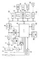
図1〜図7は第1実施の形態を示すもので、図1は撮像装置としてのデジタルスチルカメラの全体の概略構成を示すブロック図、図2は図1に示すシャッタタイミング制御回路の一例の構成を示すブロック図、図3は撮影シーン適応撮影モード時の動作を示すフローチャート、図4(a),(b)は撮影シーンの一例とその明るさ分布を示す図、図5はプリ撮影による動作を説明するための図、図6はヒストグラムのピーク値検出動作を説明するための図、図7はヒストグラムのピーク値からシャッタタイミング信号を算出する動作を説明するための図である。
【0028】
図1に示すデジタルスチルカメラは、電子シャッタ機能を有する単板式のカラーCCD撮像素子1を用いるもので、このCCD撮像素子1には、レンズ2および絞り・シャッタ機構3を経て被写体像が結像され、その被写体像が光電変換されて画像信号として出力される。CCD撮像素子1からの被写体像の画像信号は、図示しない相関二重サンプリング回路等でノイズ成分が除去されたのち、アンプ4で増幅され、さらにA/D変換器5でデジタル信号に変換されてカメラ信号処理回路6に供給され、ここで画像データとして処理される。
【0029】
また、A/D変換器5の出力は、AF,AE,AWB検波回路7およびシャッタタイミング制御回路8にも供給される。AF,AE,AWB検波回路7では、本撮影に先立ってフォーカスを自動的に制御するためのAF情報を取り出すAF検波処理、露出を自動的に制御するためのAE情報を取り出すAE検波処理、およびホワイトバランスを自動的に設定するためのAWB情報を取り出すAWB検波処理が行われる。これらのAF情報、AE情報およびAWB情報は、それぞれCPU9を介してレンズ2、絞り・シャッタ機構3およびカメラ信号処理回路6に供給されると共に、通常撮影モードではAE情報に基づいてCPU9でシャッタタイミング信号が算出されて選択スイッチ10に供給される。
【0030】
また、シャッタタイミング制御回路8では、CPU9の制御のもとに撮影シーン適応撮影モードにおいて、本撮影を行なうための撮影制御情報、本実施の形態ではシャッタタイミング信号が算出され、そのシャッタタイミング信号が選択スイッチ10およびCPU9に供給される。
【0031】
カメラ信号処理回路6およびCPU9は、バスライン11に接続され、このバスライン11には、メモリコントローラ12を介して、画像データの色処理等を行う際に作業用メモリとして用いられるDRAM13が接続されていると共に、カメラ信号処理回路6からの画像データを圧縮処理する圧縮回路(JPEG)14が接続されている。また、バスライン11には、圧縮回路14で圧縮処理された画像データをメモリカード15に記録するために、メモリカードI/F16が接続されていると共に、メモリカード15に記録された画像データを読み出して表示したり、撮影状態を表示するために表示回路17を介して液晶表示素子(LCD)18が接続されている。さらに、バスライン11には、メモリカード15に記録されている画像データをパソコン(PC)19へ転送するためのPCI/F20が接続されている。
【0032】
また、CPU9には、撮影モードに応じてAF,AE,AWB検波回路7からのAE情報あるいはシャッタタイミング制御回路8からのシャッタタイミング信号に基づいて制御されるストロボ装置21、各種撮影モードの設定やトリガスイッチの駆動等を行う入力キー22、および撮影シーン適応撮影モードにおいて本撮影に先立つプリ撮影により異なる露光条件で撮影シーンのダイナミックレンジに関する情報を取得するための複数の異なるシャッタタイミング信号、本実施の形態では3つのシャッタタイミング信号ST1,ST2,ST3を格納するシャッタタイミングROM23がそれぞれ接続されている。なお、シャッタタイミング信号ST1,ST2,ST3は、例えばST1=1/30sec、ST2=1/500sec、ST3=1/8000secとする。
【0033】
選択スイッチ10は、CPU9の制御のもとに、通常撮影モードではAE情報に基づいてCPU9で算出したシャッタタイミング信号を選択してタイミングジェネレータ(TG)24に供給し、撮影シーン適応撮影モードでは、シャッタタイミング制御回路8で算出したシャッタタイミング信号を選択してTG24に供給し、本撮影時にはシャッタタイミング制御回路8からのシャッタタイミング信号を選択してTG24に供給するようになっており、この選択スイッチ10で選択されたシャッタタイミング信号に基づいてTG24によりCCD撮像素子1の電子シャッタ機能が制御されるようになっている。
【0034】
図1に示す撮像装置では、画像合成を行わない通常撮影モードと、必要に応じて画像合成を行う撮影シーン適応撮影モードとを、入力キー22の操作により手動的に選択するか、あるいはCCD撮像素子1からの画像信号の白とびをAF,AE,AWB検波回路7からの出力に基づいてCPU9で検出して自動的に選択し、その選択した撮影モードに応じてCPU9により撮影動作を制御する。
【0035】
すなわち、通常撮影モードが選択された場合には、通常の撮影動作によって撮影シーンを一回撮影してCCD撮像素子1から一画面分の画像信号を得、その画像信号をカメラ信号処理回路6において処理する。また、撮影シーン適応撮影モードが選択された場合には、シャッタタイミングROM23に格納されている3つのシャッタタイミング信号ST1,ST2,ST3で撮影シーンを3回プリ撮影して、CCD撮像素子1から露光量の異なる3画面分のダイナミックレンジに関する情報を取得し、その取得したダイナミックレンジに関する情報に基づいて本撮影時のシャッタタイミング信号を設定して本撮影を行ない、その本撮影で得られる画像信号をカメラ信号処理回路6で処理する。
【0036】
図2は、図1に示したシャッタタイミング制御回路8の一例の構成を示すブロック図である。このシャッタタイミング制御回路8は、スイッチ31、信号合成回路32、信号分布演算回路33、信号分布解析回路34、シャッタタイミング算出回路35、およびシャッタタイミング算出用ルックアップテーブル(LUT)36を有している。
【0037】
スイッチ31は、撮影シーン適応撮影モードにおいて、プリ撮影時にのみオンとなるようにCPU9により制御し、これによりプリ撮影においてシャッタタイミング信号ST1,ST2,ST3で撮影シーンを順次撮影して得られる各画像信号(輝度信号)を、A/D変換器5を経て信号合成回路32に供給する。信号合成回路32では、入力された3画面の画像信号を撮影時の露出レベルに合わせて合成して広ダイナミックレンジの輝度情報を生成し、その輝度情報を信号分布演算回路33に供給する。
【0038】
信号分布演算回路33では、入力された広ダイナミックレンジの輝度情報に基づいて撮影シーンの輝度分布を表わすヒストグラムを演算し、その演算結果を信号分布解析回路34に供給する。信号分布解析回路34では、入力されたヒストグラムからそのピーク値の輝度を検出し、その輝度情報をシャッタタイミング算出回路35に供給する。なお、ヒストグラムに複数のピーク値が存在する場合には、その各ピーク値の輝度を検出する。
【0039】
シャッタタイミング算出回路35では、入力された輝度情報に基づいてシャッタタイミング算出用LUT36から対応するシャッタタイミング信号を読み出し、その読み出したシャッタタイミング信号をTG24に供給すると共に、シャッタタイミング信号の時間に比例してストロボの発光量を制御するためにストロボ制御用としてCPU9に供給して本撮影を行なう。なお、シャッタタイミング算出用LUT36には、輝度に対応して適正露光となるようなシャッタタイミング信号を格納しておく。
【0040】
以下、撮影シーン適応撮影モード時の動作について、図3〜図7を参照しながら更に詳細に説明する。
【0041】
図3は撮影シーン適応撮影モード時の動作を示すフローチャートである。撮影シーン適応撮影モードでは、先ず、シャッタタイミングROM23からシャッタタイミング信号ST1,ST2,ST3を読み込み(ステップS1)、そのシャッタタイミング信号ST1,ST2,ST3に基づきTG24を駆動してプリ撮影を実施し(ステップS2)、これにより異なる露光による3画面の画像信号(輝度信号)を取得する(ステップS3)。なお、ステップS2でのプリ撮影の実施は、例えばレリーズを半押しすることにより行なう。
【0042】
プリ撮影が終了したら、上述したように信号合成回路32において、各画像の輝度信号をプリ撮影時の露出レベルに合わせて合成して広ダイナミックレンジの輝度情報を算出する(ステップS4)。
【0043】
ここで、撮影シーンが図4(a)に示すように、暗い主要被写体である人物部と明るい背景部とが混在する逆光状態で、図4(b)に示すような明るさ分布を有する場合には、シャッタタイミング信号ST1,ST2,ST3でプリ撮影して、各シャッタタイミング信号での輝度情報をプリ撮影時の露出レベルに合わせると、図5に示すような撮影シーン情報が得られる。したがって、これらの輝度情報を、重複部分では明るさレベルにより重み付けして加算するようにしてステップS4で合成すれば、広ダイナミックレンジの輝度情報を得ることができる。
【0044】
例えば、各シャッタタイミング信号でのプリ撮影で得られる輝度情報が8ビットで表わされる場合に、隣接するシャッタタイミング信号で得られる輝度情報の重複部分が2ビットとなるようにシャッタタイミング信号ST1,ST2,ST3を設定すると、20ビット分(約120dB)の情報を得ることができる。
【0045】
また、実際には輝度情報を20ビットで表わすほどの明暗差が大きい撮影シーンは例外的であるので、例えば上記の重複部分を4ビットとすると、16ビット分(約96dB)の情報を得ることができる。この場合、隣接するシャッタタイミング信号の時間比は、8ビットのうち4ビットが重複することから、1:16となるので、例えば上記のようにST1=1/30sec、ST2=1/500sec、ST3=1/8000secに設定すればよい。このようにすれば、合成輝度信号Yは、シャッタタイミング信号ST1,ST2,ST3で得られる輝度信号をY1,Y2,Y3とすると、Y=Y1+16×Y2+16×16×Y3、となる。
【0046】
図3において、ステップS4で、上述したようにして広ダイナミックレンジの輝度情報を算出したら、次に、この輝度情報に基づいて信号分布演算回路33で明るさレベルによるヒストグラムを算出する(ステップS5)。ここで算出されるヒストグラムは、例えば撮影シーンが図4(a)の場合には、図6に曲線で示すようになる。
【0047】
次に、ステップS5で算出したヒストグラムから、信号分布解析回路34において、ピーク部分を検出してその輝度を求める(ステップS6)。このステップS6では、例えばヒストグラムのピーク検出間隔を予め設定し、そのピーク検出間隔におけるヒストグラム度数値(両端の値)の傾きが正から負に変化する部分をピーク値として検出して、その輝度を求める。これにより、図6のヒストグラムの場合には、人物部の斜線で示す部分の度数がピーク値として検出され、その輝度が求まる。また、前後の傾きが殆ど変化しない部分(ヒストグラム度数値の傾きが正から殆ど変化しない部分を経て負に変化する部分)については、ピークを形成している部分と判断することでその部分をピーク値として検出し、その輝度を求める。これにより、図6のヒストグラムの場合には、背景部の斜線で示す隣接する度数部分がピーク値として検出され、その輝度が求まる。したがって、撮影シーンが図4(a)の場合には、ヒストグラムのピーク値が2個検出され、それぞれの輝度が求まることになる。
【0048】
なお、ヒストグラムのピーク値は、それに相当する輝度部分が比較的適正な露光域となる撮影タイミングを求めるためのもので、図6に示したように背景部の斜線部分をピーク値として検出しても、その部分の輝度は極端に変化せず、一つの露光域に入ることになるので、必ずしも厳密に検出する必要はない。したがって、信号分布解析回路34は、簡単に構成することができる。
【0049】
ステップS6においてヒストグラムのピーク値の輝度を求めたら、シャッタタイミング算出回路35において、図7に示すようにシャッタタイミング算出用LUT36からその輝度に対応するシャッタタイミング信号を算出し(ステップS7)、その算出したシャッタタイミング信号を本撮影におけるシャッタタイミング信号として設定して(ステップS8)、そのシャッタタイミング信号により例えばレリーズ押し込みによる本撮影を行なう(ステップS9)。
【0050】
これにより、撮影シーンが図4(a)の場合には、本撮影において図7に示す1/60secおよび1/500secでの露光量の異なる2画面分の画像信号が得られることになる。この本撮影で得られる2画面分の画像信号は、カメラ信号処理回路6において公知の方法で合成処理することにより、撮影シーンに適応したダイナミックレンジの広い画像を得ることができる。
【0051】
以上のように、本実施の形態によれば、撮影シーン適応撮影モードでは、予め設定したシャッタタイミング信号ST1,ST2,ST3で撮影シーンをプリ撮影してダイナミックレンジに関する情報を取得し、その合成情報のヒストグラムを求めて、そのピーク値に対応する輝度部分が比較的適正な露光域となるシャッタタイミング信号を設定して本撮影を行なうようにしたので、明暗差が大きい撮影シーンにおいても常時AE機能を駆動することなく撮影シーンに適応した撮影を行うことができると共に、ダイナミックレンジの広い画像を再現することができる。
【0052】
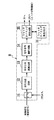
図8〜図11は第2実施の形態を示すもので、図8は撮像装置としてのデジタルスチルカメラの全体の概略構成を示すブロック図、図9は図8に示すシャッタタイミング制御・階調算出回路の一例の構成を示すブロック図、図10(a),(b)は階調変換特性の算出動作を説明するための図、図11は階調変換特性からシャッタタイミング信号を算出する動作を説明するための図である。
【0053】
本実施の形態のデジタルスチルカメラは、図1に示すシャッタタイミング制御回路8に代えて、シャッタタイミング制御・階調算出回路38を設けたもので、その他の構成は図1と同様であるので、同一作用をなすものには同一参照符号を付してその説明を省略する。
【0054】
シャッタタイミング制御・階調算出回路38は、図9に示すように、スイッチ41、信号合成回路42、信号分布演算回路43、階調変換特性算出回路44、シャッタタイミング算出回路45、およびシャッタタイミング算出用LUT46を有している。
【0055】
本実施の形態では、第1実施の形態と同様に、撮影シーン適応撮影モードにおいて、スイッチ41をプリ撮影時にのみオンとなるようにCPU9により制御して、プリ撮影においてシャッタタイミング信号ST1,ST2,ST3で順次撮影して得られる撮影シーンの各画像信号(輝度信号)を、A/D変換器5を経て信号合成回路42に供給し、ここで3画面の画像信号を撮影時の露出レベルに合わせて合成して広ダイナミックレンジの輝度情報を生成し、その輝度情報を信号分布演算回路43に供給して撮影シーンの輝度分布を表わすヒストグラムを演算する。
【0056】
信号分布演算回路43で演算されたヒストグラムは、階調変換特性算出回路44に供給し、ここで入力ヒストグラムに基づいて階調変換特性を算出する。本実施の形態では、図10(a)に示すような入力ヒストグラムから、所定の閾値以上の度数のヒストグラムを累積演算して図10(b)に示すようなノイズ等を除去した累積ヒストグラムを求め、この累積ヒストグラムを階調変換特性としてカメラ信号処理回路6に供給して、本撮影によって得られる画像信号の変換処理に用いるようにすると共に、シャッタタイミング算出回路45に供給する。
【0057】
シャッタタイミング算出回路45では、入力された階調変換特性に基づいてシャッタタイミング算出用LUT46から対応するシャッタタイミング信号を読み出し、その読み出したシャッタタイミング信号をTG24に供給すると共に、第1実施の形態と同様にストロボ制御用としてCPU9に供給して本撮影を行なう。なお、シャッタタイミング算出用LUT46には、第1実施の形態と同様に、輝度に対応して適正露光となるようなシャッタタイミング信号を格納しておく。
【0058】
ここで、階調変換特性から本撮影のシャッタタイミング信号を設定するにあたっては、図11に示すように、階調変換特性から傾きが所定値以下の部分に囲まれる領域、すなわち傾きがある領域(画像データが存在する領域)を検出し、その検出領域における累積ヒストグラムの度数を重み付けした輝度の平均値、あるいは単に検出領域における輝度範囲の中心値を求め、その求めた輝度に対応するシャッタタイミング信号をシャッタタイミング算出用LUT46から算出して設定する。
【0059】
これにより、撮影シーンが図4(a)の場合には、第1実施の形態と同様に、本撮影において図11に示す1/60secおよび1/500secでの露光量の異なる2画面分の画像信号が得られるので、この本撮影で得られる2画面分の画像信号をカメラ信号処理回路6において公知の方法で合成処理することにより、撮影シーンに適応したダイナミックレンジの広い画像を得ることができる。
【0060】
以上のように、本実施の形態によれば、撮影シーン適応撮影モードでは、予め設定したシャッタタイミング信号ST1,ST2,ST3で撮影シーンをプリ撮影してダイナミックレンジに関する情報を取得し、その合成情報のヒストグラムからノイズ等を除去した階調変換特性を求め、その階調変換特性に基づいて本撮影のシャッタタイミング信号を設定して本撮影を行なうようにしたので、明暗差が大きい撮影シーンにおいても常時AE機能を駆動することなく撮影シーンに適応したダイナミックレンジの広い画質の良好な画像を得ることができる。また、階調変換特性算出回路44で算出した階調変換特性をカメラ信号処理回路6に供給して、本撮影によって得られる画像信号の変換処理に用いるようにしているので、本撮影の画像処理で階調変換特性を求める必要がない。したがって、本撮影の画像処理を簡単かつ迅速に行なうことができる。
【0061】
なお、本発明は上記実施の形態にのみ限定されるものではなく、幾多の変形または変更が可能である。例えば、上記実施の形態では、撮影シーン適応撮影モードにおいて、撮影シーンを異なる3つのシャッタタイミング信号でプリ撮影して撮影シーンのダイナミックレンジに関する情報を取得するようにしたが、プリ撮影での異なるシャッタタイミング信号は、3つに限らず、2以上の任意の数とすることができる。また、上記実施の形態では、本撮影でのシャッタタイミング信号が2つ設定される撮影シーンの場合を例にとって説明したが、撮影シーンによっては本撮影でのシャッタタイミング信号が1つまたは3つ以上設定される場合もあるので、それに応じて1つの場合にはカメラ信号処理回路6で画像合成することなく処理し、2以上の場合には画像合成処理することにより、撮影シーンに適応した画像を得ることができる。
【0062】
また、上記実施の形態では、撮影シーン適応撮影モードでのプリ撮影および本撮影において、シャッタタイミング信号によりTG24を介してCCD撮像素子1の電子シャッタ機能を制御するようにしたが、CCD撮像素子1の電子シャッタ機能に代えて絞り・シャッタ機構3を制御したり、あるいはCCD撮像素子1の電子シャッタ機能と絞り・シャッタ機構3との双方を制御して、撮影シーンの所望の露光条件の画像信号を得るようにすることもできる。
【0063】
【発明の効果】
以上のように、本発明によれば、本撮影に先立って異なる露光条件で撮影シーンをプリ撮影してそのダイナミックレンジに関する情報を取得し、その取得したダイナミックレンジに関する情報に基づいて本撮影を行うようにしたので、明暗差が大きい撮影シーンにおいても常時AE機能を駆動することなく、撮影シーンに適応したダイナミックレンジの広い画像を得ることができる。
【図面の簡単な説明】
【図1】 本発明の第1実施の形態を示すデジタルスチルカメラの全体の概略構成を示すブロック図である。
【図2】 図1に示すシャッタタイミング制御回路の一例の構成を示すブロック図である。
【図3】 第1実施の形態による撮影シーン適応撮影モード時の動作を示すフローチャートである。
【図4】 撮影シーンの一例とその明るさ分布を示す図である。
【図5】 第1実施の形態によるプリ撮影の動作を説明するための図である。
【図6】 第1実施の形態において本撮影のシャッタタイミング信号を設定するためのヒストグラムのピーク値検出動作を説明するための図である。
【図7】 同じく、ヒストグラムのピーク値からシャッタタイミング信号を算出する動作を説明するための図である。
【図8】 本発明の第2実施の形態を示すデジタルスチルカメラの全体の概略構成を示すブロック図である。
【図9】 図8に示すシャッタタイミング制御・階調算出回路の一例の構成を示すブロック図である。
【図10】 第2実施の形態による階調変換特性の算出動作を説明するための図である。
【図11】 同じく、階調変換特性からシャッタタイミング信号を算出する動作を説明するための図である。
【図12】 広ダイナミックレンジの画像取得方法を説明するための図である。
【符号の説明】
1 CCD撮像素子
2 レンズ
3 絞り・シャッタ機構
4 アンプ
5 A/D変換器
6 カメラ信号処理回路
7 AF,AE,AWB検波回路
8 シャッタタイミング制御回路
9 CPU
10 選択スイッチ
11 バスライン
12 メモリコントローラ
13 DRAM
14 圧縮回路(JPEG)
15 メモリカード
16 メモリカードI/F
17 表示回路
18 液晶表示素子(LCD)
19 パソコン(PC)
20 PCI/F
21 ストロボ装置
22 入力キー
23 シャッタタイミングROM
24 タイミングジェネレータ(TG)
31 スイッチ
32 信号合成回路
33 信号分布演算回路
34 信号分布解析回路
35 シャッタタイミング算出回路
36 シャッタタイミング算出用LUT
38 シャッタタイミング制御・階調算出回路
41 スイッチ
42 信号合成回路
43 信号分布演算回路
44 階調変換特性算出回路
45 シャッタタイミング算出回路
46 シャッタタイミング算出用LUT[0001]
BACKGROUND OF THE INVENTION
The present invention relates to an imaging apparatus, and more particularly to an imaging apparatus capable of reproducing an image having a substantially wide dynamic range.
[0002]
[Prior art]
A digital still camera generates an image by converting light imaged on a solid-state image sensor through a lens into an electric signal. Currently, a high resolution image is generated by increasing the number of pixels. On the other hand, the dynamic range (DR) of the element itself is very narrow, so that the resulting image is latitude (bright to dark). There is a problem that the reproduction range up to the portion becomes narrow.
[0003]
In order to solve this problem, a method of generating an image having a wide dynamic range by synthesizing images obtained by performing an imaging operation a plurality of times with different exposure amounts is known. However, for example, in the case of shooting a scene with a wide dynamic range in a backlight state (mixed with a dark main subject (person) and a bright background) as shown in FIG. Depending on the shooting scene, as shown in FIGS. 12B and 12C, it is necessary to control the shooting so that the main subject and the background are appropriately exposed.
[0004]
Therefore, what is important is an automatic exposure setting (AE) function for controlling an imaging system (aperture, shutter speed, etc.) of a digital still camera from a shooting scene. For example, Japanese Patent Application Laid-Open No. 7-298142 describes a method of outputting a timing signal related to imaging system control for each of a dark part and a bright part from luminance information of an image of a photographic scene.
[0005]
[Problems to be solved by the invention]
However, in the conventional AE function, in order to control the imaging system so as to obtain an image with good reproducibility, it is necessary to always read information regarding the scene, resulting in a problem that the power consumption increases. Furthermore, when shooting multiple times with different exposures as in the above conventional example, it is necessary to read each information of the bright part and the dark part separately and control both so that they are always appropriate. There is a concern that the amount of power consumption will further increase in comparison with.
[0006]
As a countermeasure for reducing the burden on the AE function, there is a method in which either the main subject or the background is controlled by the AE function, and the exposure ratio between the captured images is separately fixed and the other exposure is adjusted. Conceivable. If the exposure ratio is fixed in this way, the AE function can be configured in the same manner as a general digital still camera.
[0007]
However, there are various cases even in a backlit state where the main subject and the background are clearly separated, and shooting may fail if the brightness changes gently between the two. In addition, when the difference in brightness between a dark indoor and a bright outdoor is very large, it may not be reproduced with an exposure ratio that is within an allowable range with normal backlight.
[0008]
Furthermore, although a method for allowing the user to specify the exposure time and the exposure ratio in the above method is also conceivable, it is difficult for the user side to determine an appropriate exposure time or exposure ratio according to the light / dark difference, and to some extent. Without experience and knowledge of this, it is difficult to determine which exposure time or exposure ratio is optimal, so it is not very practical.
[0009]
Therefore, an object of the present invention made in view of such a point is that an image having a wide dynamic range can be taken even in a shooting scene with a large contrast between light and dark without always driving the AE function. An object of the present invention is to provide an imaging device that can be reproduced.
[0012]
the above
Information acquisition means for acquiring information related to the dynamic range of the shooting scene under a plurality of exposure conditions prior to the main shooting;
Information synthesizing means for synthesizing information on the dynamic range acquired by the information acquiring means;
Histogram calculating means for calculating a histogram of the combined information combined by the information combining means;
Gradation conversion characteristic calculation means for calculating gradation conversion characteristics based on information on the histogram calculated by the histogram calculation means;
Photographing means for performing actual photographing based on the gradation conversion characteristic calculated by the gradation conversion characteristic calculating means;
It is characterized by having.
[0013]
[0014]
The photographing means includes
The image forming apparatus further includes shooting control information calculation means for calculating shooting control information for performing actual shooting based on the tone conversion characteristics calculated by the tone conversion characteristic calculation means.
[0015]
[0016]
The information relating to the dynamic range acquired by the information acquisition means is luminance information relating to the shooting scene.
[0017]
[0018]
Claim 4 The invention according to
The shooting control information calculated by the shooting control information calculation means is information for driving the shutter.
[0019]
Claim 4 According to the invention, it is possible to perform shooting with exposure adjusted to a dark part or a bright part of a shooting scene by driving a shutter as control of shooting.
[0020]
The photographing means has a flash light emitting means for irradiating light to a photographing scene, and is configured to control the flash light emitting means based on the photographing control information calculated by the photographing control information calculating means. Is.
[0021]
[0022]
The image pickup device includes information processing means for performing multiple shootings based on the shooting control information and combining image signals of a plurality of images obtained by the multiple shootings. .
[0023]
[0024]
The gradation conversion characteristic calculating means calculates a gradation conversion characteristic based on a histogram having a frequency equal to or higher than a predetermined value among the histograms calculated by the histogram calculating means.
[0025]
[0026]
DETAILED DESCRIPTION OF THE INVENTION
Hereinafter, embodiments of an imaging apparatus according to the present invention will be described with reference to FIGS.
[0027]
1 to 7 show a first embodiment. FIG. 1 is a block diagram showing an overall schematic configuration of a digital still camera as an image pickup apparatus. FIG. 2 shows an example of a shutter timing control circuit shown in FIG. FIG. 3 is a flowchart showing the operation in the shooting scene adaptive shooting mode, FIGS. 4A and 4B show an example of the shooting scene and its brightness distribution, and FIG. 5 shows the pre-shooting. FIG. 6 is a diagram for explaining the operation, FIG. 6 is a diagram for explaining the peak value detection operation of the histogram, and FIG. 7 is a diagram for explaining the operation of calculating the shutter timing signal from the peak value of the histogram.
[0028]
The digital still camera shown in FIG. 1 uses a single-plate color CCD
[0029]
The output of the A /
[0030]
In the shutter
[0031]
The camera
[0032]
Further, the
[0033]
Under the control of the
[0034]
In the imaging apparatus shown in FIG. 1, a normal shooting mode in which image synthesis is not performed and a shooting scene adaptive shooting mode in which image synthesis is performed as necessary are manually selected by operating the
[0035]
That is, when the normal shooting mode is selected, a shooting scene is shot once by a normal shooting operation to obtain an image signal for one screen from the CCD
[0036]
FIG. 2 is a block diagram showing a configuration of an example of the shutter
[0037]
The
[0038]
The signal
[0039]
The shutter
[0040]
Hereinafter, the operation in the shooting scene adaptive shooting mode will be described in more detail with reference to FIGS.
[0041]
FIG. 3 is a flowchart showing the operation in the shooting scene adaptive shooting mode. In the shooting scene adaptive shooting mode, first, shutter timing signals ST1, ST2 and ST3 are read from the shutter timing ROM 23 (step S1), and the
[0042]
When the pre-photographing is completed, as described above, the
[0043]
Here, as shown in FIG. 4 (a), the shooting scene has a brightness distribution as shown in FIG. 4 (b) in a backlit state in which a person portion that is a dark main subject and a bright background portion are mixed. In this case, pre-shooting is performed with the shutter timing signals ST1, ST2, and ST3, and the luminance information in each shutter timing signal is matched with the exposure level at the time of pre-shooting, the shooting scene information as shown in FIG. 5 is obtained. Therefore, if these pieces of luminance information are combined in step S4 so as to be weighted and added according to the brightness level in the overlapping portion, luminance information with a wide dynamic range can be obtained.
[0044]
For example, when the luminance information obtained by pre-photographing with each shutter timing signal is represented by 8 bits, the shutter timing signals ST1, ST2 so that the overlapping portion of the luminance information obtained by the adjacent shutter timing signal becomes 2 bits. , ST3, 20 bits (about 120 dB) of information can be obtained.
[0045]
Moreover, in reality, a shooting scene having a large difference in brightness so that the luminance information is represented by 20 bits is exceptional. For example, if the overlapping portion is 4 bits, information of 16 bits (about 96 dB) can be obtained. Can do. In this case, the time ratio between adjacent shutter timing signals is 1:16 because 4 bits of 8 bits are overlapped. For example, ST1 = 1/30 sec, ST2 = 1/500 sec, ST3 as described above. = 1/8000 sec. In this way, the combined luminance signal Y is Y = Y1 + 16 × Y2 + 16 × 16 × Y3, where Y1, Y2 and Y3 are the luminance signals obtained from the shutter timing signals ST1, ST2 and ST3.
[0046]
In FIG. 3, after the luminance information of the wide dynamic range is calculated as described above in step S4, the histogram based on the brightness level is calculated by the signal
[0047]
Next, from the histogram calculated in step S5, the signal
[0048]
Note that the peak value of the histogram is used to determine the shooting timing at which the corresponding luminance portion has a relatively appropriate exposure area. As shown in FIG. 6, the shaded portion of the background portion is detected as the peak value. However, since the luminance of the portion does not change extremely and enters one exposure area, it is not always necessary to detect it precisely. Therefore, the signal
[0049]
When the luminance of the peak value of the histogram is obtained in step S6, the shutter timing
[0050]
As a result, when the shooting scene is FIG. 4A, image signals for two screens having different exposure amounts at 1/60 sec and 1/500 sec shown in FIG. 7 are obtained in the main shooting. The image signals for the two screens obtained by the actual photographing are combined in the camera
[0051]
As described above, according to the present embodiment, in the shooting scene adaptive shooting mode, the shooting scene is pre-shot with the preset shutter timing signals ST1, ST2, and ST3 to acquire information on the dynamic range, and the combined information Since the main shooting is performed by setting the shutter timing signal in which the luminance portion corresponding to the peak value is a relatively appropriate exposure area, the AE function is always used even in a shooting scene with a large contrast. It is possible to perform shooting suitable for a shooting scene without driving the, and to reproduce an image with a wide dynamic range.
[0052]
FIGS. 8 to 11 show a second embodiment. FIG. 8 is a block diagram showing an overall schematic configuration of a digital still camera as an imaging apparatus. FIG. 9 is a shutter timing control / gradation calculation shown in FIG. FIG. 10A and FIG. 10B are diagrams for explaining the calculation operation of the gradation conversion characteristics, and FIG. 11 shows the operation of calculating the shutter timing signal from the gradation conversion characteristics. It is a figure for demonstrating.
[0053]
The digital still camera of the present embodiment is provided with a shutter timing control /
[0054]
As shown in FIG. 9, the shutter timing control /
[0055]
In this embodiment, as in the first embodiment, in the shooting scene adaptive shooting mode, the
[0056]
The histogram calculated by the signal
[0057]
The shutter
[0058]
Here, when setting the shutter timing signal for the actual photographing from the gradation conversion characteristics, as shown in FIG. 11, the area surrounded by the gradation conversion characteristics with a predetermined value or less, that is, the area with the inclination ( Area where image data exists), and the average value of the luminance obtained by weighting the frequency of the cumulative histogram in the detection area or simply the center value of the luminance range in the detection area is obtained, and the shutter timing signal corresponding to the obtained luminance Is calculated from the shutter
[0059]
As a result, when the shooting scene is FIG. 4A, as in the first embodiment, images for two screens with different exposure amounts at 1/60 sec and 1/500 sec shown in FIG. Since a signal is obtained, an image with a wide dynamic range adapted to the photographic scene can be obtained by synthesizing the image signals for two screens obtained by the main photographing in the camera
[0060]
As described above, according to the present embodiment, in the shooting scene adaptive shooting mode, the shooting scene is pre-shot with the preset shutter timing signals ST1, ST2, and ST3 to acquire information on the dynamic range, and the combined information The tone conversion characteristics with noise and the like removed from the histogram, and the main shooting shutter timing signal is set based on the tone conversion characteristics, so that the main shooting is performed. It is possible to obtain a good image with a wide dynamic range adapted to the shooting scene without always driving the AE function. Further, since the gradation conversion characteristic calculated by the gradation conversion
[0061]
It should be noted that the present invention is not limited to the above-described embodiment, and many variations or modifications can be made. For example, in the above-described embodiment, in the shooting scene adaptive shooting mode, the shooting scene is pre-shot with three different shutter timing signals to acquire information on the dynamic range of the shooting scene. The number of timing signals is not limited to three, and can be any number of two or more. In the above embodiment, the case of a shooting scene in which two shutter timing signals are set for actual shooting has been described as an example. However, depending on the shooting scene, one or more shutter timing signals for main shooting are used. In some cases, the camera
[0062]
In the above embodiment, the electronic shutter function of the CCD
[0063]
【Effect of the invention】
As described above, according to the present invention, prior to the main shooting, the shooting scene is pre-shot under different exposure conditions to acquire information about the dynamic range, and the main shooting is performed based on the acquired information about the dynamic range. Thus, an image with a wide dynamic range adapted to the shooting scene can be obtained without always driving the AE function even in a shooting scene having a large difference in brightness.
[Brief description of the drawings]
FIG. 1 is a block diagram showing an overall schematic configuration of a digital still camera showing a first embodiment of the present invention.
FIG. 2 is a block diagram showing a configuration of an example of a shutter timing control circuit shown in FIG.
FIG. 3 is a flowchart showing an operation in a shooting scene adaptive shooting mode according to the first embodiment.
FIG. 4 is a diagram illustrating an example of a shooting scene and its brightness distribution.
FIG. 5 is a diagram for explaining a pre-photographing operation according to the first embodiment;
FIG. 6 is a diagram for explaining a peak value detection operation of a histogram for setting a shutter timing signal for actual photographing in the first embodiment.
FIG. 7 is also a diagram for explaining an operation for calculating a shutter timing signal from a peak value of a histogram.
FIG. 8 is a block diagram showing an overall schematic configuration of a digital still camera showing a second embodiment of the present invention.
9 is a block diagram showing a configuration of an example of a shutter timing control / tone calculation circuit shown in FIG. 8;
FIG. 10 is a diagram for explaining an operation of calculating gradation conversion characteristics according to the second embodiment.
FIG. 11 is also a diagram for explaining an operation of calculating a shutter timing signal from gradation conversion characteristics.
FIG. 12 is a diagram for explaining a wide dynamic range image acquisition method;
[Explanation of symbols]
1 CCD image sensor
2 Lens
3 Aperture / Shutter Mechanism
4 amplifiers
5 A / D converter
6 Camera signal processing circuit
7 AF, AE, AWB detection circuit
8 Shutter timing control circuit
9 CPU
10 Selection switch
11 Bus line
12 Memory controller
13 DRAM
14 Compression circuit (JPEG)
15 Memory card
16 Memory card I / F
17 Display circuit
18 Liquid crystal display (LCD)
19 PC
20 PCI / F
21 Strobe device
22 Input keys
23 Shutter timing ROM
24 Timing generator (TG)
31 switches
32 Signal synthesis circuit
33 Signal distribution calculation circuit
34 Signal distribution analysis circuit
35 Shutter timing calculation circuit
36 LUT for shutter timing calculation
38 Shutter timing control / tone calculation circuit
41 switch
42 Signal synthesis circuit
43 Signal distribution calculation circuit
44 Gradation conversion characteristic calculation circuit
45 Shutter timing calculation circuit
46 LUT for shutter timing calculation
Claims (7)
該情報取得手段で取得されたダイナミックレンジに関する情報を合成する情報合成手段と、
前記情報合成手段で合成された合成情報のヒストグラムを算出するヒストグラム演算手段と、
前記ヒストグラム演算手段で算出されたヒストグラムに関する情報に基づいて階調変換特性を算出する階調変換特性演算手段と、
前記階調変換特性演算手段で算出された階調変換特性に基づいて本撮影を行う撮影手段と、
を有することを特徴とする撮像装置。Information acquisition means for acquiring information related to the dynamic range of the shooting scene under a plurality of exposure conditions prior to the main shooting;
Information synthesizing means for synthesizing information on the dynamic range acquired by the information acquiring means;
Histogram calculating means for calculating a histogram of the combined information combined by the information combining means;
Gradation conversion characteristic calculation means for calculating gradation conversion characteristics based on information on the histogram calculated by the histogram calculation means;
Photographing means for performing actual photographing based on the gradation conversion characteristic calculated by the gradation conversion characteristic calculating means;
An imaging device comprising:
前記階調変換特性演算手段で算出された階調変換特性に基づいて本撮影を行うための撮影制御情報を算出する撮影制御情報演算手段を有することを特徴とする請求項1に記載の撮像装置。The photographing means includes
The imaging apparatus according to claim 1 , further comprising shooting control information calculation means for calculating shooting control information for performing actual shooting based on the tone conversion characteristics calculated by the tone conversion characteristic calculation means. .
Priority Applications (3)
| Application Number | Priority Date | Filing Date | Title |
|---|---|---|---|
| JP2000326522A JP4869474B2 (en) | 2000-10-26 | 2000-10-26 | Imaging device |
| US10/045,530 US7298402B2 (en) | 2000-10-26 | 2001-10-23 | Image-pickup apparatus with expanded dynamic range capabilities |
| EP01125302A EP1202563A1 (en) | 2000-10-26 | 2001-10-25 | Image-pickup apparatus |
Applications Claiming Priority (1)
| Application Number | Priority Date | Filing Date | Title |
|---|---|---|---|
| JP2000326522A JP4869474B2 (en) | 2000-10-26 | 2000-10-26 | Imaging device |
Publications (3)
| Publication Number | Publication Date |
|---|---|
| JP2002135648A JP2002135648A (en) | 2002-05-10 |
| JP2002135648A5 JP2002135648A5 (en) | 2008-05-22 |
| JP4869474B2 true JP4869474B2 (en) | 2012-02-08 |
Family
ID=18803695
Family Applications (1)
| Application Number | Title | Priority Date | Filing Date |
|---|---|---|---|
| JP2000326522A Expired - Fee Related JP4869474B2 (en) | 2000-10-26 | 2000-10-26 | Imaging device |
Country Status (1)
| Country | Link |
|---|---|
| JP (1) | JP4869474B2 (en) |
Families Citing this family (14)
| Publication number | Priority date | Publication date | Assignee | Title |
|---|---|---|---|---|
| JP3948229B2 (en) * | 2001-08-01 | 2007-07-25 | ソニー株式会社 | Image capturing apparatus and method |
| JP2006108759A (en) | 2004-09-30 | 2006-04-20 | Fuji Photo Film Co Ltd | Imaging apparatus |
| JP4630730B2 (en) | 2005-05-27 | 2011-02-09 | キヤノン株式会社 | Imaging apparatus, camera, and imaging method |
| JP4693602B2 (en) * | 2005-11-07 | 2011-06-01 | 株式会社東芝 | Imaging apparatus and image signal processing method |
| JP4628937B2 (en) * | 2005-12-01 | 2011-02-09 | オリンパス株式会社 | Camera system |
| JP4860551B2 (en) | 2007-06-01 | 2012-01-25 | 株式会社キーエンス | Magnification observation apparatus, high gradation image file creation method, high gradation image file creation method, high gradation image file creation program, and computer-readable recording medium |
| JP5188101B2 (en) | 2007-06-01 | 2013-04-24 | 株式会社キーエンス | Magnification observation apparatus, magnified image photographing method, magnified image photographing program, and computer-readable recording medium |
| JP4986747B2 (en) | 2007-07-09 | 2012-07-25 | キヤノン株式会社 | Imaging apparatus and imaging method |
| JP5220657B2 (en) * | 2009-02-26 | 2013-06-26 | オリンパス株式会社 | Imaging apparatus and image processing program |
| JP5701664B2 (en) | 2011-04-07 | 2015-04-15 | オリンパス株式会社 | Imaging device |
| JP6120500B2 (en) | 2012-07-20 | 2017-04-26 | キヤノン株式会社 | Imaging apparatus and control method thereof |
| JP2015041890A (en) * | 2013-08-22 | 2015-03-02 | ソニー株式会社 | Controller, control method and electronic apparatus |
| JP6786273B2 (en) | 2016-06-24 | 2020-11-18 | キヤノン株式会社 | Image processing equipment, image processing methods, and programs |
| JP7230658B2 (en) * | 2019-04-16 | 2023-03-01 | 株式会社デンソー | Image processing device |
-
2000
- 2000-10-26 JP JP2000326522A patent/JP4869474B2/en not_active Expired - Fee Related
Also Published As
| Publication number | Publication date |
|---|---|
| JP2002135648A (en) | 2002-05-10 |
Similar Documents
| Publication | Publication Date | Title |
|---|---|---|
| US7298402B2 (en) | Image-pickup apparatus with expanded dynamic range capabilities | |
| TWI293846B (en) | Image pickup device with brightness correcting function and method of correcting brightness of image | |
| KR100819804B1 (en) | Photographing apparatus | |
| JP4869474B2 (en) | Imaging device | |
| JP4554094B2 (en) | Imaging device | |
| US20030214600A1 (en) | Digital camera | |
| JP4136464B2 (en) | Imaging apparatus and imaging method | |
| JP4641571B2 (en) | Digital still camera and control method thereof | |
| JP2008148180A (en) | Imaging apparatus, image processing device and method, and computer program | |
| JP4568484B2 (en) | Image processing method and digital camera | |
| JP4458194B2 (en) | Imaging apparatus, exposure control method thereof, and recording medium | |
| JP3974798B2 (en) | Imaging device | |
| JP2004180151A (en) | Digital camera | |
| JP4285668B2 (en) | Imaging apparatus, exposure control method thereof, and recording medium | |
| JP6231814B2 (en) | EXPOSURE DETERMINING DEVICE, IMAGING DEVICE, CONTROL METHOD, AND PROGRAM | |
| JP2000307921A (en) | Picture processor | |
| JP2004129065A (en) | Digital camera | |
| JPH10322592A (en) | Method and device for controlling electronic camera | |
| JP4335648B2 (en) | Digital camera and imaging method of digital camera | |
| JP4422353B2 (en) | Electronic camera | |
| JP2003242504A (en) | Image processor | |
| JP4274207B2 (en) | Imaging apparatus, exposure control method thereof, and recording medium | |
| JP2004222160A (en) | Digital camera | |
| JP2001209782A (en) | Image pickup device and its method for photographing character | |
| JP2003069872A (en) | Imaging device, image output device, image processing system, image output method and program |
Legal Events
| Date | Code | Title | Description |
|---|---|---|---|
| A621 | Written request for application examination |
Free format text: JAPANESE INTERMEDIATE CODE: A621 Effective date: 20071024 |
|
| A521 | Request for written amendment filed |
Free format text: JAPANESE INTERMEDIATE CODE: A523 Effective date: 20080403 |
|
| A977 | Report on retrieval |
Free format text: JAPANESE INTERMEDIATE CODE: A971007 Effective date: 20090615 |
|
| A131 | Notification of reasons for refusal |
Free format text: JAPANESE INTERMEDIATE CODE: A131 Effective date: 20090623 |
|
| A521 | Request for written amendment filed |
Free format text: JAPANESE INTERMEDIATE CODE: A523 Effective date: 20090810 |
|
| RD03 | Notification of appointment of power of attorney |
Free format text: JAPANESE INTERMEDIATE CODE: A7423 Effective date: 20090810 |
|
| A02 | Decision of refusal |
Free format text: JAPANESE INTERMEDIATE CODE: A02 Effective date: 20091006 |
|
| A01 | Written decision to grant a patent or to grant a registration (utility model) |
Free format text: JAPANESE INTERMEDIATE CODE: A01 |
|
| A61 | First payment of annual fees (during grant procedure) |
Free format text: JAPANESE INTERMEDIATE CODE: A61 Effective date: 20111116 |
|
| FPAY | Renewal fee payment (event date is renewal date of database) |
Free format text: PAYMENT UNTIL: 20141125 Year of fee payment: 3 |
|
| LAPS | Cancellation because of no payment of annual fees |