JP4866657B2 - Plastic pallet - Google Patents
Plastic pallet Download PDFInfo
- Publication number
- JP4866657B2 JP4866657B2 JP2006141595A JP2006141595A JP4866657B2 JP 4866657 B2 JP4866657 B2 JP 4866657B2 JP 2006141595 A JP2006141595 A JP 2006141595A JP 2006141595 A JP2006141595 A JP 2006141595A JP 4866657 B2 JP4866657 B2 JP 4866657B2
- Authority
- JP
- Japan
- Prior art keywords
- wall
- synthetic resin
- pallet
- corner
- plate
- Prior art date
- Legal status (The legal status is an assumption and is not a legal conclusion. Google has not performed a legal analysis and makes no representation as to the accuracy of the status listed.)
- Active
Links
Images


Description
本発明は、種々の物品を運搬および保管する際などに使用される合成樹脂製パレットに関するものであって、特に軽量で座屈強度の高い合成樹脂製パレットに関する。 The present invention relates to a synthetic resin pallet used when transporting and storing various articles, and more particularly to a synthetic resin pallet that is lightweight and has high buckling strength.
従来、物品を運搬および保管する際に使用される合成樹脂製パレットとして、二方差しのパレットや四方差しのパレットが使用されている。四方差しの合成樹脂製パレットとして、例えば特許文献1、2に記載のものがある。
この種の合成樹脂製パレットは略四角形箱状に形成され、互いに平行に配置された上面板状部(上面デッキプレート)及び下面板状部(下面デッキプレート)と、上面板状部及び下面板状部を連結する複数の桁部とから概略構成されている。
桁部は、四方差しパレットの場合には対向する上面及び下面板状部の4つのコーナー部と、各側面における隣り合うコーナー部間の中間部、上面及び下面板状部の中央部とにそれぞれ配設されている。そして、この合成樹脂製パレットの四辺をなす各側面には両側コーナー部の桁部と中間部の桁部との間にフォークの挿入孔を形成する一対の挿通孔がそれぞれ設けられ、これら挿通孔はフォークリフトやパレットトラックのフォークが挿入される。
そして対向する側面の各挿入孔が互いに連通しており、これら挿入孔は平面視で井桁形状に連通して四方差しのパレットを構成している。また、合成樹脂製パレットの下面板状部には、例えばパレットトラックが二本の挿通孔に挿入される際に、フォークの先端に取り付けられた車輪が落ち込むための車輪用孔が各2ヶ所に設けられている。
Conventionally, a two-way pallet or a four-way pallet is used as a synthetic resin pallet used when transporting and storing articles. Examples of four-way synthetic resin pallets include those described in
This kind of synthetic resin pallet is formed in a substantially rectangular box shape, and is arranged in parallel with each other, an upper surface plate portion (upper surface deck plate) and a lower surface plate shape portion (lower surface deck plate), and an upper surface plate shape portion and a lower surface plate. And a plurality of girder parts connecting the shaped parts.
In the case of a four-way pallet, the girder is provided at the four corners of the upper and lower plate-like portions facing each other, the middle portion between adjacent corner portions on each side, and the central portion of the upper and lower plate-like portions, respectively. It is arranged. Each side surface forming the four sides of the synthetic resin pallet is provided with a pair of insertion holes for forming insertion holes for the forks between the spar portions of the corners on both sides and the spar portion of the intermediate portion. Forklifts and pallet truck forks are inserted.
The insertion holes on the opposite side surfaces communicate with each other, and these insertion holes communicate in a cross beam shape in plan view to constitute a four-way pallet. In addition, the bottom plate-shaped part of the synthetic resin pallet has, for example, two wheel holes each for dropping the wheel attached to the tip of the fork when a pallet truck is inserted into the two insertion holes. Is provided.
ところで、上述した合成樹脂製パレットの中には、船舶や飛行機等に乗せて輸出入する物品を積載したり、物品を運搬や保管するために積載するために用いられるものがある。このようなパレットの一部は輸出や輸入、或いは運搬、保管等に用いて、繰り返し使用されるが、他の一部のパレットは輸送コストや破損、衛生上の理由等のために輸出先または輸入先等で廃棄されたり他の用途にリサイクル等され、パレットとしてそのまま再使用されない。このような輸出入や運搬等の際に1回のみ使用されて処分されるようなパレットを1ウエイパレットという。
繰り返し使用する通常のパレットは二方差しや四方差しのいずれの場合でも、例えば10kg前後の重量を有しており、座屈強度(破壊荷重)として動荷重で1トン程度、静荷重で2トン程度以下の荷重に耐え得るようになっている。他方、1ウエイパレットは軽量化によるコスト低減のために重量は通常のパレットより小さく(例えば6kg前後)抑えられている。
A normal pallet that is used repeatedly has a weight of, for example, around 10 kg in either two-way or four-way insertion, and the buckling strength (breaking load) is about 1 ton for dynamic load and 2 ton for static load. It can withstand loads of less than about. On the other hand, the weight of the one-way pallet is smaller than that of a normal pallet (for example, around 6 kg) in order to reduce the cost by reducing the weight.
しかしながら、1ウエイパレットであっても、物品を積載して輸送、保管等する際には物品の荷重で座屈等が発生して荷崩れしないだけの座屈強度が必要であり、しかも1回使用のために製造コストを可能な限り低減するよう合成樹脂の使用量を落として軽量化することが要求されている。
例えば、1ウエイパレットが溶着接合構造の場合、射出成形等によって上面板状部及び上部桁部からなる上部パートと下面板状部及び下部桁部からなる下部パートとが別個に製造され、各桁部同士を対向させた状態で加熱溶着によって接合している。この場合、軽量化・低コスト化のためにパレットを構成する各リブ等の肉厚を比較的小さくすると、溶着構造の1ウエイパレットは溶着部分の座屈強度が比較的小さいために物品の積載荷重によって亀裂が入り易く座屈し易いという欠点がある。
また桁部の溶着部には溶着バリが突出形成されて見栄えが悪かった。この溶着バリを切除すると工程数が増えて製造コストが増大する欠点が生じる。これを防ぐために桁部の溶着部に凹部を形成し、溶着バリが凹部内に収容されて外部に突出しないようにしたものもあるが、この場合には溶着部における凹部の強度が比較的小さくなるために応力集中が起こり、一層座屈を生じ易いという欠点が発生する。
また1ウエイパレットが一体成形構造である場合には、溶着部がないために接合部での座屈強度の低下を生じないが、この場合でも軽量化・低コスト化のために合成樹脂の使用量を低減させると座屈強度が低下するという欠点を改善できなかった。
However, even with a one-way pallet, it is necessary to have a buckling strength sufficient to prevent the load from collapsing when the article is loaded, transported, stored, etc. In order to reduce the manufacturing cost as much as possible for use, it is required to reduce the amount of synthetic resin used to reduce the weight.
For example, when a one-way pallet has a welded joint structure, an upper part composed of an upper plate part and an upper girder part and a lower part composed of a lower plate part and a lower girder part are manufactured separately by injection molding or the like, and each girder It joins by heat welding in the state which made the parts oppose. In this case, if the thickness of each rib constituting the pallet is relatively small in order to reduce the weight and cost, the one-way pallet with a welded structure has a relatively small buckling strength at the welded portion, so that the loading of articles can be performed. There is a drawback that it is easy to crack due to the load and to be easily buckled.
Further, the welding burrs protruded from the welded portion of the girder portion, and the appearance was bad. When this welding burr is cut off, the number of processes increases and the manufacturing cost increases. In order to prevent this, a recess is formed in the welding portion of the girder so that the welding burr is accommodated in the recess so that it does not protrude outside. In this case, the strength of the recess in the welding portion is relatively small. As a result, stress concentration occurs, and there is a drawback that buckling is more likely to occur.
In addition, when the one-way pallet has an integrally molded structure, there is no welded portion, so there is no reduction in buckling strength at the joint, but even in this case, synthetic resin is used to reduce weight and cost. It was not possible to improve the drawback of reducing the buckling strength when the amount was reduced.
本発明は、このような実情に鑑みて、座屈強度を確保しながら合成樹脂量を低減させて製造コストを低減できるようにした合成樹脂製パレットを提供することを目的とする。 In view of such a situation, an object of the present invention is to provide a synthetic resin pallet that can reduce the manufacturing cost by reducing the amount of the synthetic resin while ensuring the buckling strength.
本発明による合成樹脂製パレットは、互いに対向して配置された上面板状部及び下面板状部と、上面板状部及び下面板状部を連結する複数の桁部と、上面板状部及び下面板状部の間の外側に位置する側面部における隣り合う桁部間を通って延びる挿入孔が形成されてなる四方差し用の合成樹脂製パレットであって、前記側面部の各コーナー部に位置する前記桁部である隅桁部は、四角形状の開口部を有する枠形状に形成されて互いに直交する二つの外壁と、前記開口部と向い合う四角形状の第二開口部を有する枠形状に形成されて前記外壁の交差部から対角方向に延びる対角補強板とを有し、前記外壁の内縁と前記対角補強板の内縁とが上面板状部及び下面板状部に沿う補強板で連結されている一体成形によって形成されてなることを特徴とする。
本発明によれば、合成樹脂製パレットの側面部に配設された桁部の外壁に開口部が形成されているために合成樹脂の使用量が低減し軽量化と製造コストの低減を達成でき、しかも側面部に設けた桁部の外壁は合成樹脂製パレットの外側端縁に位置するため物品荷重があまりかからず、強度低下の影響が小さいから座屈を生じ難い。
A synthetic resin pallet according to the present invention includes an upper surface plate-like portion and a lower surface plate-like portion that are arranged to face each other, a plurality of girders that connect the upper surface plate-like portion and the lower surface plate-like portion, an upper surface plate-like portion, A synthetic resin pallet for four-way insertion, in which insertion holes extending between adjacent beam portions in the side surface portions located on the outside between the lower surface plate-like portions are formed , and each corner portion of the side surface portion is formed. The corner girder, which is the girder , is formed in a frame shape having a quadrangular opening and is formed in a frame shape having two outer walls orthogonal to each other and a quadrangular second opening facing the opening. And a diagonal reinforcing plate extending diagonally from the intersection of the outer walls, and the inner edge of the outer wall and the inner edge of the diagonal reinforcing plate are reinforced along the upper surface plate-shaped portion and the lower surface plate-shaped portion. and characterized by being formed by integral molding are connected by a plate That.
According to the present invention, since the opening is formed in the outer wall of the girder portion disposed on the side surface portion of the synthetic resin pallet, the amount of the synthetic resin used can be reduced, and weight reduction and manufacturing cost reduction can be achieved. Moreover, since the outer wall of the girder portion provided on the side surface portion is located on the outer edge of the synthetic resin pallet, the load on the article is not so much, and the influence of the strength reduction is small, so that buckling is unlikely to occur.
本発明に係わる合成樹脂製パレットによれば、側面部に配設された桁部の外壁に開口部を形成したために合成樹脂の使用量が低減し軽量化と製造コストの低減を達成でき、しかも側面部に設けた桁部の外壁は合成樹脂製パレットの外側端縁に位置するため過大な物品荷重がかかることはなく、パレットの座屈強度を確保できる。 According to the synthetic resin pallet according to the present invention, since the opening is formed in the outer wall of the girder portion arranged on the side surface portion, the amount of the synthetic resin used can be reduced, the weight can be reduced, and the manufacturing cost can be reduced. Since the outer wall of the girder portion provided on the side surface portion is located at the outer edge of the synthetic resin pallet, an excessive load on the article is not applied, and the buckling strength of the pallet can be secured.
本発明の実施の形態による合成樹脂製パレットでは、側面部の各コーナー部に位置する桁部は、二つの外壁の交差部から対角方向に対角補強板が設けられていることが好ましい。
対角補強板によって桁部の強度を補強できるため、交差する二つの外壁にそれぞれ開口部を設けても桁部や合成樹脂製パレットの座屈強度を向上できる。なお、対角補強板に開口を設けてもよく、この場合には強度低下を抑えてより軽量化できる。
また、側面部の各コーナー部に位置する桁部は、外壁に対向する内壁が設けられた略角筒状とされ、内壁から外壁方向に向けて補強板が設けられていることが好ましく、これによって、桁部の内側の強度を補強できるため、物品の荷重がかかっても高い座屈強度を確保できる。この場合、補強板は対角補強板または外壁に連結されていることが好ましく、また補強板には開口部が設けられていてもいなくてもよい。
また、外壁に形成された開口部は仕切板によって分割されていてもよく、仕切板によって桁部の外壁、合成樹脂製パレットの外側縁部を補強できる。
更に、本発明による合成樹脂製パレットは一体成形によって形成されてなることが好ましく、軽量化しても溶着接合構造によるパレットのように桁部の溶着部で座屈し易いという欠点が生じない。
なお、側面部に設けた桁部としてコーナー部の隅桁部、同一側面部における二つの隅桁部間の中間桁部が含まれており、桁部の圧縮強度は隅角部と中間桁部とで担うために、これら両桁部の重量を軽減しつつ強度を向上させることで高い座屈強度が得られる。
In the synthetic resin pallet according to the embodiment of the present invention, it is preferable that a diagonal reinforcing plate is provided diagonally from the intersection of the two outer walls in the girder located at each corner of the side surface.
Since the strength of the girder portion can be reinforced by the diagonal reinforcing plate, the buckling strength of the girder portion or the synthetic resin pallet can be improved even if openings are provided in the two intersecting outer walls. In addition, you may provide an opening in a diagonal reinforcement board, and can reduce weight by suppressing a strength fall in this case.
Further, the girder portion located at each corner portion of the side surface portion is preferably a substantially rectangular tube shape having an inner wall facing the outer wall, and a reinforcing plate is preferably provided from the inner wall toward the outer wall. Therefore, the strength inside the girder can be reinforced, so that a high buckling strength can be ensured even when a load is applied to the article. In this case, the reinforcing plate is preferably connected to a diagonal reinforcing plate or an outer wall, and the reinforcing plate may or may not be provided with an opening.
Moreover, the opening part formed in the outer wall may be divided | segmented by the partition plate, and the outer wall of a girder part and the outer edge part of a synthetic resin pallet can be reinforced with a partition plate.
Furthermore, it is preferable that the synthetic resin pallet according to the present invention is formed by integral molding, and even if the weight is reduced, there is no disadvantage that it is easily buckled at the welded portion of the spar, unlike a pallet having a welded joint structure.
In addition, the corner girder part of the corner part and the intermediate girder part between the two corner girder parts on the same side surface part are included as the girder part provided on the side surface part. Therefore, a high buckling strength can be obtained by improving the strength while reducing the weight of both the girder portions.
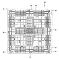
以下、本発明の実施例による合成樹脂製パレットを図1乃至図9により説明する。図1は合成樹脂製パレットの上面側から見た斜視図、図2は同じく裏面側から見た斜視図、図3は平面図、図4は側面図、図5は裏面図、図6は図1に示すパレットのコーナー部分の斜視図、図7は図4のA−A線水平断面図、図8は図3におけるコーナー部の桁部のB−B線縦断面図、図9は同じく中間部桁部のC−C線縦断面図である。
図1及び図2に示す実施例による合成樹脂製パレット1は全体として四角形、例えば略正方形の箱形を呈しており、合成樹脂製パレット1の上面部を形成する上面板状部(上面デッキプレート)2と、裏面部を形成する下面板状部(下面デッキプレート)3と、上面板状部2および下面板状部3にそれぞれ設けられた複数の桁部4とを有している。上面板状部2と下面板状部3は対向して概略平行に配設され、上面板状部2及び下面板状部3間の四辺の領域はそれぞれ側面部5を構成する。
Hereinafter, a synthetic resin pallet according to an embodiment of the present invention will be described with reference to FIGS. 1 is a perspective view of the synthetic resin pallet as viewed from the top side, FIG. 2 is a perspective view of the same as seen from the back side, FIG. 3 is a plan view, FIG. 4 is a side view, FIG. 5 is a back view, and FIG. 7 is a horizontal sectional view taken along the line AA in FIG. 4, FIG. 8 is a vertical sectional view taken along the line BB of the spar of the corner portion in FIG. 3, and FIG. It is a CC line longitudinal cross-sectional view of a part girder part.
The synthetic resin pallet 1 according to the embodiment shown in FIGS. 1 and 2 has a rectangular shape, for example, a substantially square box shape as a whole, and an upper surface plate-like portion (upper surface deck plate) that forms the upper surface portion of the synthetic resin pallet 1. ) 2, a lower surface plate-shaped portion (lower surface deck plate) 3 that forms the back surface portion, and a plurality of
合成樹脂製パレット1は、上面板状部2及び下面板状部3と両者を連結する複数の桁部4とが一体に成形されている。桁部4は、パレット1即ち上面板状部2及び下面板状部3の4つのコーナー部6Aに設けた隅桁部4a、…と、4面の側面部5における両側コーナー部6A、6Aの隅桁部4a,4a間の中間にそれぞれ設けた4本の中間桁部6b、…と、対向する二対の中間桁部4b、…の中間即ちパレット1の中央に設けた中央桁部4cとで構成されている。
そして、対向する二側面部5、5における桁部4a、4b間に設けた各一対のフォーク挿入孔7、7は互いに連通する挿通孔8、8を構成する。そのため挿通孔8,8は、各側面部5における一対のフォーク挿通孔7,7からフォークリフトやパレットトラックのフォークを挿入するための2列の空間として平行に形成されている。そのため、各二列の挿通孔8、8は互いに略直交して連通し、平面視で略井桁形状を構成している。
The synthetic resin pallet 1 is integrally formed with an upper surface plate-
And a pair of
次に上面板状部2は、各桁部4a〜4cの上端に連結されていて略田の字形状をなす格子状のエッジプレート部10と、エッジプレート部10で仕切られていてエッジプレート部10より例えば格子の目が粗い四つの格子プレート部11とで構成されている。
また、下面板状部3は、各桁部4a〜4cの下端に連結されていて略田の字形状をなす格子状の桟部12と、桟部12で仕切られた四つの開口である車輪用孔13とで構成されている。車輪用孔13は、フォーク挿入孔7,7から挿入されるパレットトラックの車輪が落ち込むための開口である。図に示す例では、車輪用孔13は各一対の挿通孔8、8の長手方向に沿ってそれぞれ2個づつ所定間隔で設けられている。
なお、合成樹脂製パレット1は、全体に例えばポリプロピレン等の合成樹脂からなる。また、これら合成樹脂全量がバージン材で形成されていてもよいし、内部にリサイクル材としての合成樹脂を混入していてもよい。
上述のように上面板状部2及び下面板状部3は全体にそれぞれ大小の中空部を有する格子状に形成されている。
Next, the upper surface plate-
The lower surface plate-
The synthetic resin pallet 1 is entirely made of synthetic resin such as polypropylene. The total amount of these synthetic resins may be formed of a virgin material, or a synthetic resin as a recycled material may be mixed therein.
As described above, the upper surface plate-
次に各コーナー部6Aにおける隅桁部4aについて図6乃至図8に沿って詳述する。
図6及び図7に示すように、各コーナー部6Aの隅桁部4aは略角筒状、例えば略四角筒形状に形成され、側面部5の領域において隅桁部4aの互いに略直交する二つの外壁14、14は略四角形の開口部15、15が穿孔されており、その周囲の四辺がリブ14a、14bを構成する枠形状を有している。隅桁部4aの外壁14、14から開口部15、15を切除することで、隅桁部4aの重量を軽減して製造コストを低減できる。
更に隅桁部4aの互いに略直交する二つの内壁16、16は開口部を設けない板状の壁面を構成し、高い強度を備えてパレット1に曲げ剛性を付与している。外壁14,14で形成する角部と内壁16,16で形成する角部とを結ぶ対角線方向には板状の対角補強板17が設けられており、対角補強板17には図8に示すように第二開口部18が穿孔されている。この第二開口部18は対角補強板17の対角方向両端近傍まで延びており、これによってパレット1の各コーナー部6Aの強度を補強すると共に重量の増大を抑えている。
また、各内壁16、16には各内壁16に略直交する方向に複数(1枚でもよい)の第一補強板20、20が所定間隔で略平行に連結されている。しかも、各第一補強板20は外壁14側に開口する略四角形の切り欠け部21によって内側が切除されているために平面視略コ字状に形成されており、その他端は外壁14のリブ14a、14aに接続されている。二面の内壁16、16から突出する各第一補強板20,…は対角補強板17で互いに略直交して相互に連結され、平面視で格子状とされている。
隅桁部4aの各第一補強板20も切り欠け部21を切除することで、強度を補強すると共に隅桁部4aの重量を軽減できる。
Next, the
As shown in FIGS. 6 and 7, the
Further, the two
In addition, a plurality (or one) of first reinforcing
Each first reinforcing
なお、隅桁部4aの外壁14に関し、外壁14の縦寸法をa、横寸法をbとしてその面積をA(=a×b)とした場合(図4参照)、外壁14に対する開口部15の面積比は50%〜80%の範囲に設定する。この範囲が隅桁部4aの座屈と軽量化の観点から見てバランスがとれる。また、面積比65%〜75%とすればより好ましい。
In addition, regarding the
次に中間桁部4bは略角筒状、例えば略四角筒形状に形成され、側面部5の領域において中間桁部4bの外壁23には開口部24が形成され、周囲にリブ23a、23bが枠状に形成されている。中間桁部4bの他の三つの内壁25a、25b,25aには開口部は設けられておらず、外壁23に略直交する二つの内壁25a、25a間には第三開口26aを設けた複数の第三補強板26、…が平行に連結されている。
外壁23に対向する内壁25bには複数の第四補強板27a、27bが切り欠け部28a、28bを有する平面視略コ字状の設けられている。中央の第四補強板27aは図9に示すように内壁25bから外壁23のリブ23a、23aに延びて連結され、その両側の第四補強板27b、27bは第三補強板26に延びて連結されている。
また、中央桁部4cは例えば略四角筒形状に形成され、その四つの内壁は開口のない板状に形成されている。中央桁部4c内には互いに直交する格子状壁面が配設され、これら格子状壁面は他の壁面との連結部を除いて上下方向に略長方形の貫通孔が穿孔されている。
なお、中間桁部4bの外壁23に関し、外壁23の縦寸法をa′、横寸法をb′としてその面積をA′(=a′×b′)とした場合(図4参照)、外壁23に対する開口部24の面積比は隅桁部4aと同様に50%〜80%の範囲に設定し、好ましくは面積比65%〜75%とする。この範囲で中間桁部4bの座屈と軽量化のバランスがとれる。
Next, the
On the
Further, the
Regarding the
本実施例による合成樹脂製パレット1は上述の構成を備えているから、特にパレット1の各コーナー部6Aに設けた隅桁部4aの外壁14、14にそれぞれ開口部15を設けたことでパレット1の重量を軽減でき、対向補強板17と互いに直交する複数(実施例では4枚)の第一補強板20を設けたことで隅桁部4aやパレット1の全体の強度を補強でき、しかも内側に第二開口部18、切り欠け部21を設けることでパレット重量を軽減できる。特にパレット1の上面板状部2に積載する物品等はパレット1の外周縁にまで位置することが殆どなく、通常、各コーナー部6Aの隅桁部4aの内側角部に重なる程度の位置まで物品が積載されるために、パレット1の強度を効果的に補強でき、座屈を防止できる。
また、中間桁部4bにおいても、外壁23に開口部24を設けて重量を軽減し、更に中間桁部4bの内部に格子状をなす第三補強板26及び第四補強板27a、27bを設けると共にこれらに第三開口部26a、切り欠け部28a、28bを穿孔することで、重量を抑制しつつ強度を補強でき、座屈を防止できる。
Since the synthetic resin pallet 1 according to the present embodiment has the above-described configuration, the pallet is provided by providing
Also in the
特に従来技術で説明したように、1ウエイパレット等の軽量化した合成樹脂製パレットを上部パートと下部パートに分割して成形した後に溶着で接合した溶着接合構造では、成形と溶着で加熱と冷却を繰り返すことと溶着部(接合部)を有するために座屈を生じ易かった。これを補うために各桁部を開口や切り欠けのない略筒状に形成しているが、座屈強度が小さいという欠点があった。
これに対し、本実施例による合成樹脂製パレット1は一体成形で製造し、積載する物品の荷重がかかりにくい各桁部4a、4bの外側部分である外壁14、23に開口部15,24を形成して軽量化し、各桁部4a、4bの内側部分である内壁16,25a、25bに開口部を設けないことと対角補強板17等で強度と曲げ剛性を確保した。これによってパレット1の軽量化と高い座屈強度を同時に達成でき、しかも低廉で1ウエイパレットとしても用いることができる。
In particular, as explained in the prior art, in a welded joint structure in which a lightweight plastic resin pallet such as a one-way pallet is formed by dividing it into an upper part and a lower part and then joined by welding, heating and cooling are performed by molding and welding. It was easy to produce buckling because of having repeated welding and having a welding part (joining part). In order to compensate for this, each girder portion is formed in a substantially cylindrical shape having no openings or notches, but has a drawback of low buckling strength.
On the other hand, the synthetic resin pallet 1 according to the present embodiment is manufactured by integral molding, and the
従って、本実施例による合成樹脂製パレット1は4つのコーナー部6Aにおける隅桁部4aと4つの中間桁部4bで重量を軽減しつつ強度を補強することで、軽量化による製造コストの低減と座屈強度の向上とを同時に達成できる。よって1ウエイパレットとして用いても経済的である。
Therefore, the synthetic resin pallet 1 according to the present embodiment reduces the manufacturing cost by reducing the weight by reinforcing the strength while reducing the weight at the
次に本発明の第二実施例を図10乃至図14により説明するが、第一実施例との相違点は主としてコーナー部6Aの隅桁部4aと中間桁部4bであり、第一実施例と同一または同様の部分、部材には同一の符号を用いて説明を省略し、相違点を中心に説明する。
図10乃至図14に示す本実施例による合成樹脂製パレット30において、各コーナー部6Aの隅桁部4aは外壁14の開口部41a、41bは仕切板42によって複数、例えば2つに分割されており、外壁14,14の角部と内壁16、16の角部とを連結する対角補強板43には開口は設けられていない。更に各内壁16に直交する方向には複数(図では2枚)の第五補強板44、44がそれぞれ形成されて対角補強板43に連結されている。各第五補強板44、44にはそれぞれ第五開口部46、46が穿孔され、重量を軽減しつつ強度を補強している。
また、中間桁部4bは例えば略四角筒形状に形成され、中間桁部4bの外壁23には二つの開口部49a、49bが形成され、周囲にリブ23a、23bが枠状に形成されている。中間桁部4bの他の三つの内壁25a、25b,25aには開口部は設けられておらず、外壁23に略直交する二つの内壁25a、25a間にはそれぞれ第六開口部50aを設けた複数(図では2枚)の第六補強板50、…が所定間隔で平行に連結されている。
また、外壁23に対向する内壁25bには切り欠けや開口のない板状をなす複数の第二仕切板51a、第三仕切板51bが設けられている。中央の第二仕切板51aは二枚の第六補強板50,50に直交してリブ23a、23aに連結され、外壁23の開口を二つの開口部49a、49bに分けている。第二仕切板51aの両側に位置する第三仕切板51b、51bは第六補強板50に連結されている。
Next, the second embodiment of the present invention will be described with reference to FIGS. 10 to 14. The difference from the first embodiment is mainly the
In the
Further, the
The
中間桁部4bは外壁23を除く3つの内壁25a、25b、25aと中央桁部4cに近い内壁25bから外壁23に向かって延びる3枚の第二、第三仕切板51a、51b、51bに開口等を形成しないことで、パレット30の内側部分の強度と曲げ剛性を高くし、外壁23やこれに略平行な第六補強板50、50に開口部49a、49b、第六開口部50a、50aを穿孔することでパレット30の重量を軽減して製造コストを低減させることができる。
The
従って、本実施例によるパレット30においても、第一実施例と同様に4つの隅桁部4aと4つの中間桁部4bで重量を軽減しつつ強度を補強することで、軽量化による製造コストの低減と軽量化に関わらず座屈強度の向上とを同時に達成できる。よって1ウエイパレットとして用いても経済的である。
Therefore, also in the
次に実施例による合成樹脂パレット1、30と比較例について脚部圧縮試験を行った。
第一実施例による合成樹脂パレット1を実施例1、第二実施例によるものを実施例2、出願人の既存物品として桁部に開口部を設けないもの(商品名EXA−1111)を比較例1、上述の従来技術で説明した他社物品による溶着接合構造の合成樹脂パレットを比較例2とした。
各パレットの材質は100%バージン樹脂によるポリプロピレンであり、全体重量は実施例1、2が6.0kg、比較例1が7.3kg、比較例2が5.9kgである。各パレットは片面四方差し構造とし、寸法は1100(縦)×1100(横)×120(高さ)(mm)とした。また、各実施例1,2、比較例1,2において、それぞれの隅桁部の外形寸法を195×195(mm)、中間桁部の外形寸法を195×190(mm)とし、隅桁部と中間桁部の各リブの肉厚を2.5mmとした。
なお、実施例1における隅桁部4aの第一補強壁20の平面視における内壁16から切り欠け部21までの長さを27.5mm、対角補強板17の外壁14,14の角部から第二開口部18までの長さを35mm、同じく内壁16,16の角部から第二開口部18までの長さを23mmとする。中間桁部4bにおける各第三補強板26の内壁25aから第三開口26aまでの長さを27.5mm、第四補強板27a、27bの内壁25bから切り欠け部28a、28bまでの長さを27.5mmとした。
実施例2における隅桁部4aの対角補強板43には開口部はなく、第五補強壁44の平面視における内壁16から切り欠け部46までの長さを10.5mmとする。開口部41a、41bの仕切板42の寸法は120×50mmとした。中間桁部4bにおける各第六補強板50の各内壁25aから第六開口部50aまでの長さを10.5mm、第二、第三仕切板51a、51bは開口部がない。
Next, a leg compression test was performed on the
The synthetic resin pallet 1 according to the first embodiment is the first embodiment, the second embodiment is the second embodiment, the applicant's existing article is not provided with an opening in the girder (trade name EXA-1111) is a comparative example 1. A synthetic resin pallet with a welded joint structure made by another company's article described in the above-mentioned prior art was used as Comparative Example 2.
The material of each pallet is 100% virgin resin polypropylene, and the total weight is 6.0 kg in Examples 1 and 2, 7.3 kg in Comparative Example 1, and 5.9 kg in Comparative Example 2. Each pallet had a single-sided four-way structure, and the dimensions were 1100 (vertical) × 1100 (horizontal) × 120 (height) (mm). In each of Examples 1 and 2 and Comparative Examples 1 and 2, the outer dimensions of the respective corner beams are 195 × 195 (mm), the outer dimensions of the intermediate beam are 195 × 190 (mm), and the corner beams are And the thickness of each rib of the intermediate girder part was 2.5 mm.
In addition, the length from the
The diagonal reinforcing
脚部圧縮試験はJIS規定に準拠したもので、コーナー部の各隅桁部に平面寸法20cm×20cmの鉄板を置いて加圧試験を行った。
試験結果はコーナー部の隅桁部の各測定値の平均値をとった。得られた座屈強度(耐圧荷重)は、実施例1で2.5t(トン)、実施例2で2.3t、比較例1で3.3t、比較例2で2.1tであった。
試験結果から、座屈強度は実施例1,2がいずれも比較例2より高く、比較例1より小さかった。重量は既存物品である比較例1が大きく、実施例1、2、比較例2はほぼ同等であった。
The leg compression test was based on JIS regulations, and a pressure test was performed by placing an iron plate having a plane size of 20 cm × 20 cm on each corner girder.
The test result was the average of the measured values of the corner girder. The buckling strength (pressure load) obtained was 2.5 t (tons) in Example 1, 2.3 t in Example 2, 3.3 t in Comparative Example 1, and 2.1 t in Comparative Example 2.
From the test results, the buckling strength was higher in both Examples 1 and 2 than Comparative Example 2 and smaller than Comparative Example 1. The weight of Comparative Example 1, which is an existing article, was large, and Examples 1, 2, and Comparative Example 2 were almost equivalent.
なお、上述の各実施例では、合成樹脂パレット1,30について隅桁部4aと中間桁部4bの各外壁14,23に開口部15、24を設けたが、隅桁部4aにだけ外壁14に開口部15を設けてもよい。この場合、隅桁部4aに対角補強板17,43は必ずしも設けなくてもよい。
本発明による合成樹脂パレットは必ずしも1ウエイパレットでなくてもよく、再使用可能な合成樹脂パレットとしても使用できる。
In each of the above-described embodiments, the
The synthetic resin pallet according to the present invention is not necessarily a one-way pallet and can be used as a reusable synthetic resin pallet.
1、30 合成樹脂製パレット
2 上面板状部
3 下面板状部
4、4a 桁部
4b 中間桁部
4c 中央桁部
5 側面部
6A コーナー部
7 フォーク挿入孔(挿入孔)
14、23 外壁
15、24、41a、41b、49a、49b 開口部
16、25a、25b 内壁
17、43 対角補強板
18 第二開口部
20 第一補強板
21、28a、28b 切り欠け部
26 第三補強板
27a、27b 第四補強板
42 仕切板
44 第五補強板
50 第六補強板
50a 第六開口部
51a 第二仕切板
51b 第三仕切板
DESCRIPTION OF
14, 23
Claims (4)
前記側面部の各コーナー部に位置する前記桁部である隅桁部は、
四角形状の開口部を有する枠形状に形成されて互いに直交する二つの外壁と、
前記開口部と向い合う四角形状の第二開口部を有する枠形状に形成されて前記外壁の交差部から対角方向に延びる対角補強板とを有し、
前記外壁の内縁と前記対角補強板の内縁とが上面板状部及び下面板状部に沿う補強板で連結されている
一体成形によって形成されてなる合成樹脂製パレット。 Between the upper surface plate-shaped portion and the lower surface plate-shaped portion, the upper surface plate-shaped portion, the lower surface plate-shaped portion, the plurality of girders that connect the upper surface plate-shaped portion and the lower surface plate-shaped portion, A synthetic resin pallet for four-way insertion, in which an insertion hole extending between the adjacent beam portions in the side surface portion located on the outside is formed,
The corner girder part, which is the girder part located at each corner part of the side part ,
Two outer walls formed in a frame shape having a rectangular opening and orthogonal to each other;
A diagonal reinforcing plate formed in a frame shape having a quadrangular second opening facing the opening and extending diagonally from the intersection of the outer walls;
The inner edge of the outer wall and the inner edge of the diagonal reinforcing plate are connected by a reinforcing plate along the upper surface plate portion and the lower surface plate portion.
A synthetic resin pallet formed by integral molding .
四角形状の開口部を有する枠形状に形成された一つの外壁と、
前記一つの外壁に連結されて該外壁と直交する二つの内壁と、
前記一つの外壁と対向するように前記二つの内壁間を連結し、前記一つの外壁に形成された前記開口部と対向する四角形状の第三開口部を有する枠形状に形成された補強板とを有する
請求項1に記載の合成樹脂製パレット。 The intermediate girder part, which is the girder part sandwiched between two corner girder parts,
One outer wall formed in a frame shape having a rectangular opening,
Two inner walls connected to the one outer wall and orthogonal to the outer wall;
A reinforcing plate formed in a frame shape having a quadrangular third opening that connects the two inner walls so as to face the one outer wall and faces the opening formed in the one outer wall; The pallet made of synthetic resin according to claim 1.
該外壁の表面積に対する該外壁に形成された前記開口部の占める割合が、50%〜80%である
請求項1または2に記載の合成樹脂製パレット。 In the two outer walls in the corner beam,
The synthetic resin pallet according to claim 1 or 2, wherein a ratio of the opening formed in the outer wall to a surface area of the outer wall is 50% to 80% .
該外壁の表面積に対する該外壁に形成された前記開口部の占める割合が、50%〜80%である
請求項1乃至3のいずれか一項に記載の合成樹脂製パレット。 In the one outer wall in the intermediate beam part,
The synthetic resin pallet according to any one of claims 1 to 3, wherein a ratio of the opening formed in the outer wall to a surface area of the outer wall is 50% to 80% .
Priority Applications (1)
| Application Number | Priority Date | Filing Date | Title |
|---|---|---|---|
| JP2006141595A JP4866657B2 (en) | 2006-05-22 | 2006-05-22 | Plastic pallet |
Applications Claiming Priority (1)
| Application Number | Priority Date | Filing Date | Title |
|---|---|---|---|
| JP2006141595A JP4866657B2 (en) | 2006-05-22 | 2006-05-22 | Plastic pallet |
Publications (2)
| Publication Number | Publication Date |
|---|---|
| JP2007308192A JP2007308192A (en) | 2007-11-29 |
| JP4866657B2 true JP4866657B2 (en) | 2012-02-01 |
Family
ID=38841420
Family Applications (1)
| Application Number | Title | Priority Date | Filing Date |
|---|---|---|---|
| JP2006141595A Active JP4866657B2 (en) | 2006-05-22 | 2006-05-22 | Plastic pallet |
Country Status (1)
| Country | Link |
|---|---|
| JP (1) | JP4866657B2 (en) |
Families Citing this family (1)
| Publication number | Priority date | Publication date | Assignee | Title |
|---|---|---|---|---|
| JP6128589B2 (en) * | 2013-03-13 | 2017-05-17 | 三甲株式会社 | Resin pallet |
Family Cites Families (9)
| Publication number | Priority date | Publication date | Assignee | Title |
|---|---|---|---|---|
| JPS6042000B2 (en) * | 1977-02-25 | 1985-09-19 | バブコツク日立株式会社 | Waste liquid furnace peroxidation equipment |
| JPS54157945A (en) * | 1978-06-03 | 1979-12-13 | Meiji Gomu Kasei Kk | Pallet in synthetic resin |
| JPS5550904A (en) * | 1978-10-12 | 1980-04-14 | Nippon Kokan Kk <Nkk> | Manufacture of cold rolled steel sheet of high lankford value |
| CA1246470A (en) * | 1985-06-21 | 1988-12-13 | Andrew Gyenge | Collapsible storage bin |
| US4917255A (en) * | 1989-02-24 | 1990-04-17 | J.I.T. Corporation | Collapsible container |
| JP2922819B2 (en) * | 1995-03-30 | 1999-07-26 | 株式会社明治ゴム化成 | Plastic pallets |
| JP4216368B2 (en) * | 1998-06-30 | 2009-01-28 | 三甲株式会社 | Plastic pallet |
| JP4105891B2 (en) * | 2002-04-22 | 2008-06-25 | 岐阜プラスチック工業株式会社 | Plastic pallet |
| JP2004203482A (en) * | 2002-10-29 | 2004-07-22 | Myoko Kikai Kogyo Kk | Plastic pallet |
-
2006
- 2006-05-22 JP JP2006141595A patent/JP4866657B2/en active Active
Also Published As
| Publication number | Publication date |
|---|---|
| JP2007308192A (en) | 2007-11-29 |
Similar Documents
| Publication | Publication Date | Title |
|---|---|---|
| US20100154685A1 (en) | Pallet having great dimensional stability and load- bearing capacity | |
| US20100326334A1 (en) | Reinforced plastic pallet | |
| MX2013000709A (en) | Metallic pallet with frame and panel support surface. | |
| JP4017097B2 (en) | Plastic pallet | |
| KR101115606B1 (en) | Structure for reinforcing strength in pallet | |
| JP4866657B2 (en) | Plastic pallet | |
| WO2014034660A1 (en) | Resin pallet | |
| JP4557255B2 (en) | Plastic pallet | |
| KR101610910B1 (en) | Multipurpose steel pallets | |
| JP4421496B2 (en) | Plastic pallet | |
| JP4931140B2 (en) | Plastic pallet | |
| JP3919036B2 (en) | Plastic pallet | |
| JP2577134Y2 (en) | Loading pallets | |
| JP2922838B2 (en) | Plastic pallets | |
| JP7399455B2 (en) | palette | |
| JP6496512B2 (en) | palette | |
| JP7382051B2 (en) | palette | |
| JP7368828B2 (en) | palette | |
| JP3227135U (en) | palette | |
| JP5563797B2 (en) | Plastic pallet | |
| JP4991264B2 (en) | palette | |
| JP6932369B2 (en) | palette | |
| JP4326354B2 (en) | Plastic pallet | |
| JPH0547070Y2 (en) | ||
| JP3201581B2 (en) | Skid palette |
Legal Events
| Date | Code | Title | Description |
|---|---|---|---|
| A621 | Written request for application examination |
Free format text: JAPANESE INTERMEDIATE CODE: A621 Effective date: 20090216 |
|
| A977 | Report on retrieval |
Free format text: JAPANESE INTERMEDIATE CODE: A971007 Effective date: 20110527 |
|
| A131 | Notification of reasons for refusal |
Free format text: JAPANESE INTERMEDIATE CODE: A131 Effective date: 20110712 |
|
| RD03 | Notification of appointment of power of attorney |
Free format text: JAPANESE INTERMEDIATE CODE: A7423 Effective date: 20110728 |
|
| A711 | Notification of change in applicant |
Free format text: JAPANESE INTERMEDIATE CODE: A711 Effective date: 20110713 |
|
| RD04 | Notification of resignation of power of attorney |
Free format text: JAPANESE INTERMEDIATE CODE: A7424 Effective date: 20110802 |
|
| A521 | Request for written amendment filed |
Free format text: JAPANESE INTERMEDIATE CODE: A523 Effective date: 20110831 |
|
| TRDD | Decision of grant or rejection written | ||
| A01 | Written decision to grant a patent or to grant a registration (utility model) |
Free format text: JAPANESE INTERMEDIATE CODE: A01 Effective date: 20111101 |
|
| A01 | Written decision to grant a patent or to grant a registration (utility model) |
Free format text: JAPANESE INTERMEDIATE CODE: A01 |
|
| A61 | First payment of annual fees (during grant procedure) |
Free format text: JAPANESE INTERMEDIATE CODE: A61 Effective date: 20111114 |
|
| FPAY | Renewal fee payment (event date is renewal date of database) |
Free format text: PAYMENT UNTIL: 20141118 Year of fee payment: 3 |
|
| R150 | Certificate of patent or registration of utility model |
Ref document number: 4866657 Country of ref document: JP Free format text: JAPANESE INTERMEDIATE CODE: R150 Free format text: JAPANESE INTERMEDIATE CODE: R150 |
|
| R154 | Certificate of patent or utility model (reissue) |
Free format text: JAPANESE INTERMEDIATE CODE: R154 |
|
| R250 | Receipt of annual fees |
Free format text: JAPANESE INTERMEDIATE CODE: R250 |
|
| R250 | Receipt of annual fees |
Free format text: JAPANESE INTERMEDIATE CODE: R250 |
|
| R250 | Receipt of annual fees |
Free format text: JAPANESE INTERMEDIATE CODE: R250 |
|
| R250 | Receipt of annual fees |
Free format text: JAPANESE INTERMEDIATE CODE: R250 |