JP4866417B2 - Image processing apparatus, image processing method, and image processing program - Google Patents
Image processing apparatus, image processing method, and image processing program Download PDFInfo
- Publication number
- JP4866417B2 JP4866417B2 JP2008503875A JP2008503875A JP4866417B2 JP 4866417 B2 JP4866417 B2 JP 4866417B2 JP 2008503875 A JP2008503875 A JP 2008503875A JP 2008503875 A JP2008503875 A JP 2008503875A JP 4866417 B2 JP4866417 B2 JP 4866417B2
- Authority
- JP
- Japan
- Prior art keywords
- shot
- similar
- frame
- generating
- generation
- Prior art date
- Legal status (The legal status is an assumption and is not a legal conclusion. Google has not performed a legal analysis and makes no representation as to the accuracy of the status listed.)
- Expired - Fee Related
Links
- 238000012545 processing Methods 0.000 title claims description 60
- 238000003672 processing method Methods 0.000 title claims description 15
- 238000000034 method Methods 0.000 claims description 189
- 230000033001 locomotion Effects 0.000 claims description 164
- 238000001514 detection method Methods 0.000 claims description 23
- 238000010586 diagram Methods 0.000 description 56
- 230000008569 process Effects 0.000 description 46
- 230000015654 memory Effects 0.000 description 41
- 238000003860 storage Methods 0.000 description 38
- 238000013139 quantization Methods 0.000 description 28
- 239000013598 vector Substances 0.000 description 23
- 230000006870 function Effects 0.000 description 19
- 230000008859 change Effects 0.000 description 9
- 230000009466 transformation Effects 0.000 description 9
- 238000012937 correction Methods 0.000 description 8
- 238000006243 chemical reaction Methods 0.000 description 5
- 230000001186 cumulative effect Effects 0.000 description 5
- 230000009467 reduction Effects 0.000 description 5
- 230000006835 compression Effects 0.000 description 4
- 238000007906 compression Methods 0.000 description 4
- 238000007796 conventional method Methods 0.000 description 3
- 230000008707 rearrangement Effects 0.000 description 3
- 238000004904 shortening Methods 0.000 description 3
- PXFBZOLANLWPMH-UHFFFAOYSA-N 16-Epiaffinine Natural products C1C(C2=CC=CC=C2N2)=C2C(=O)CC2C(=CC)CN(C)C1C2CO PXFBZOLANLWPMH-UHFFFAOYSA-N 0.000 description 2
- 238000012935 Averaging Methods 0.000 description 2
- 238000004364 calculation method Methods 0.000 description 2
- 238000004519 manufacturing process Methods 0.000 description 2
- 230000001131 transforming effect Effects 0.000 description 2
- SZGNWRSFHADOMY-UHFFFAOYSA-N 2-[2-[2-[2-[2-[2-[2-(2-methoxyethoxy)ethoxy]ethoxy]ethoxy]ethoxy]ethoxy]ethoxy]ethanol Chemical group COCCOCCOCCOCCOCCOCCOCCOCCO SZGNWRSFHADOMY-UHFFFAOYSA-N 0.000 description 1
- 241000255777 Lepidoptera Species 0.000 description 1
- 230000002457 bidirectional effect Effects 0.000 description 1
- 230000005540 biological transmission Effects 0.000 description 1
- 230000008602 contraction Effects 0.000 description 1
- 238000006073 displacement reaction Methods 0.000 description 1
- 238000009826 distribution Methods 0.000 description 1
- 238000011156 evaluation Methods 0.000 description 1
- 238000000605 extraction Methods 0.000 description 1
- 230000006872 improvement Effects 0.000 description 1
- 230000010354 integration Effects 0.000 description 1
- 230000004048 modification Effects 0.000 description 1
- 238000012986 modification Methods 0.000 description 1
- 230000003287 optical effect Effects 0.000 description 1
- 230000002123 temporal effect Effects 0.000 description 1
Images


Classifications
-
- H—ELECTRICITY
- H04—ELECTRIC COMMUNICATION TECHNIQUE
- H04N—PICTORIAL COMMUNICATION, e.g. TELEVISION
- H04N19/00—Methods or arrangements for coding, decoding, compressing or decompressing digital video signals
- H04N19/50—Methods or arrangements for coding, decoding, compressing or decompressing digital video signals using predictive coding
- H04N19/503—Methods or arrangements for coding, decoding, compressing or decompressing digital video signals using predictive coding involving temporal prediction
- H04N19/51—Motion estimation or motion compensation
- H04N19/527—Global motion vector estimation
-
- H—ELECTRICITY
- H04—ELECTRIC COMMUNICATION TECHNIQUE
- H04N—PICTORIAL COMMUNICATION, e.g. TELEVISION
- H04N19/00—Methods or arrangements for coding, decoding, compressing or decompressing digital video signals
- H04N19/10—Methods or arrangements for coding, decoding, compressing or decompressing digital video signals using adaptive coding
- H04N19/102—Methods or arrangements for coding, decoding, compressing or decompressing digital video signals using adaptive coding characterised by the element, parameter or selection affected or controlled by the adaptive coding
- H04N19/103—Selection of coding mode or of prediction mode
- H04N19/105—Selection of the reference unit for prediction within a chosen coding or prediction mode, e.g. adaptive choice of position and number of pixels used for prediction
-
- H—ELECTRICITY
- H04—ELECTRIC COMMUNICATION TECHNIQUE
- H04N—PICTORIAL COMMUNICATION, e.g. TELEVISION
- H04N19/00—Methods or arrangements for coding, decoding, compressing or decompressing digital video signals
- H04N19/10—Methods or arrangements for coding, decoding, compressing or decompressing digital video signals using adaptive coding
- H04N19/102—Methods or arrangements for coding, decoding, compressing or decompressing digital video signals using adaptive coding characterised by the element, parameter or selection affected or controlled by the adaptive coding
- H04N19/103—Selection of coding mode or of prediction mode
- H04N19/114—Adapting the group of pictures [GOP] structure, e.g. number of B-frames between two anchor frames
-
- H—ELECTRICITY
- H04—ELECTRIC COMMUNICATION TECHNIQUE
- H04N—PICTORIAL COMMUNICATION, e.g. TELEVISION
- H04N19/00—Methods or arrangements for coding, decoding, compressing or decompressing digital video signals
- H04N19/10—Methods or arrangements for coding, decoding, compressing or decompressing digital video signals using adaptive coding
- H04N19/134—Methods or arrangements for coding, decoding, compressing or decompressing digital video signals using adaptive coding characterised by the element, parameter or criterion affecting or controlling the adaptive coding
- H04N19/142—Detection of scene cut or scene change
-
- H—ELECTRICITY
- H04—ELECTRIC COMMUNICATION TECHNIQUE
- H04N—PICTORIAL COMMUNICATION, e.g. TELEVISION
- H04N19/00—Methods or arrangements for coding, decoding, compressing or decompressing digital video signals
- H04N19/10—Methods or arrangements for coding, decoding, compressing or decompressing digital video signals using adaptive coding
- H04N19/169—Methods or arrangements for coding, decoding, compressing or decompressing digital video signals using adaptive coding characterised by the coding unit, i.e. the structural portion or semantic portion of the video signal being the object or the subject of the adaptive coding
- H04N19/177—Methods or arrangements for coding, decoding, compressing or decompressing digital video signals using adaptive coding characterised by the coding unit, i.e. the structural portion or semantic portion of the video signal being the object or the subject of the adaptive coding the unit being a group of pictures [GOP]
-
- H—ELECTRICITY
- H04—ELECTRIC COMMUNICATION TECHNIQUE
- H04N—PICTORIAL COMMUNICATION, e.g. TELEVISION
- H04N19/00—Methods or arrangements for coding, decoding, compressing or decompressing digital video signals
- H04N19/46—Embedding additional information in the video signal during the compression process
-
- H—ELECTRICITY
- H04—ELECTRIC COMMUNICATION TECHNIQUE
- H04N—PICTORIAL COMMUNICATION, e.g. TELEVISION
- H04N19/00—Methods or arrangements for coding, decoding, compressing or decompressing digital video signals
- H04N19/50—Methods or arrangements for coding, decoding, compressing or decompressing digital video signals using predictive coding
- H04N19/503—Methods or arrangements for coding, decoding, compressing or decompressing digital video signals using predictive coding involving temporal prediction
- H04N19/51—Motion estimation or motion compensation
-
- H—ELECTRICITY
- H04—ELECTRIC COMMUNICATION TECHNIQUE
- H04N—PICTORIAL COMMUNICATION, e.g. TELEVISION
- H04N19/00—Methods or arrangements for coding, decoding, compressing or decompressing digital video signals
- H04N19/60—Methods or arrangements for coding, decoding, compressing or decompressing digital video signals using transform coding
- H04N19/61—Methods or arrangements for coding, decoding, compressing or decompressing digital video signals using transform coding in combination with predictive coding
Landscapes
- Engineering & Computer Science (AREA)
- Multimedia (AREA)
- Signal Processing (AREA)
- Compression Or Coding Systems Of Tv Signals (AREA)
Description
この発明は、動画像を符号化あるいは復号する画像処理装置、画像処理方法、および画像処理プログラムに関する。ただし本発明の利用は、上述した画像処理装置、画像処理方法、および画像処理プログラムに限らない。 The present invention relates to an image processing apparatus, an image processing method, and an image processing program for encoding or decoding a moving image. However, use of the present invention is not limited to the above-described image processing apparatus, image processing method, and image processing program.
動画像の符号化における符号効率の向上、動画像へのアクセス方法の多様化、動画像のブラウジングの容易化、ファイル形式変換の容易化などといった様々な目的で、動画像の構造化(具体的にはフレーム順序の並び替え、ショット単位での階層化など)を行う従来技術としては、たとえば下記特許文献1〜5に記載の発明などがあった。
Structuring of moving images for various purposes such as improvement of coding efficiency in moving image coding, diversification of access methods to moving images, ease of browsing of moving images, ease of file format conversion, etc. As conventional techniques for performing frame order rearrangement, hierarchization in units of shots, and the like, for example, there have been inventions described in
このうち特許文献1に記載の従来技術では、ファイル作成手段により動画像データのフレーム単位での並び替え順序を示す編集情報を作成する。また、画像圧縮手段は編集前の動画像データを前フレームとの差分を基に圧縮符号化し、その符号化データを上記編集情報ファイルと共に出力手段から送信する。
Among them, in the prior art described in
また、特許文献2に記載の従来技術では、画像データ列メモリ部に保存された予測符号化画像データを読み出し、階層分離部でそのデータ構造が持つ階層に応じて階層に分離する。次に、分離された階層から画像データの持つ物理的特徴、すなわち一般性を有しコンテントを反映した特徴を、画像特徴抽出部にて抽出する。次に、これらの物理的特徴から各々の画像を特徴付ける特徴ベクトルを特徴ベクトル生成部にて生成する。次に、その特徴ベクトル間での距離を算出して特徴ベクトルを、分割・統合部にて分割・統合して映像を深い階層構造で自動的に構造化し、特徴ベクトル管理部にて蓄積、管理する。 In the prior art described in Patent Document 2, predictive encoded image data stored in the image data string memory unit is read out, and is divided into hierarchies according to the hierarchies of the data structure in the hierarchy separating unit. Next, a physical feature of the image data, that is, a feature having generality and reflecting the content is extracted from the separated hierarchy by the image feature extraction unit. Next, a feature vector that characterizes each image is generated by the feature vector generation unit from these physical features. Next, the distance between the feature vectors is calculated, and the feature vectors are divided and integrated by the division / integration unit, and the video is automatically structured in a deep hierarchical structure, and stored and managed by the feature vector management unit To do.
また、特許文献3に記載の従来技術は、動画像を符号化し、該符号化された動画像を各ショットに分割し、ついで分割されたショットごとの類似度を用い、ショットを統合してシーンを抽出処理することを特徴とした動画像の自動階層構造化方法であり、かつまたこの階層構造化されたデータを用いて動画像全体の内容把握、所望のシーンまたはショットの検出を容易にすることを特徴とした動画像のブラウジング方法にかかるものである。 The prior art described in Patent Document 3 encodes a moving image, divides the encoded moving image into shots, and then uses the similarity for each divided shot to integrate the shots into a scene. Is a method for automatically structuring a moving image characterized in that the image is extracted, and using this hierarchically structured data, it is possible to easily grasp the contents of the entire moving image and to detect a desired scene or shot. The present invention relates to a moving image browsing method characterized by the above.
また、特許文献4に記載の従来技術では、複数のカメラで撮像した複数チャンネルの映像信号を切替手段で順番に切り替え、並び替え手段でチャンネルごとにGOP単位で並び替え、MPEG圧縮手段で圧縮して記録手段に記録するとともに、MPEG伸長手段で各チャンネルごとに伸長し、表示制御手段で映像データを多画面表示できるように、データサイズを圧縮して複数の表示用メモリの所定位置に各チャンネルの入力順にまとめて保存、再生し、画像出力手段がモニタの1画面に多画面表示する。 In the prior art described in Patent Document 4, video signals of a plurality of channels picked up by a plurality of cameras are sequentially switched by a switching unit, rearranged by a rearrangement unit for each channel, and compressed by an MPEG compression unit. The data is compressed and the data size is compressed so that the video data can be displayed on multiple screens by the display control means, and each channel is placed at a predetermined position in a plurality of display memories. Are stored and played back in the order of input, and the image output means displays a multi-screen on one screen of the monitor.
また、特許文献5に記載の従来技術では、第1の動画像符号化データ形式であるMPEG−2形式のビットストリームA1をMPEG−2デコーダによりデコードして得られた再生動画像信号A2およびサイド情報A3をサイズ変換部により第2の動画像符号化データ形式であるMPEG−4形式に適した形態に変換し、変換後の再生画像信号A4を変換後のサイド情報A5に含まれる動きベクトル情報を利用してMPEG−4エンコーダによってエンコードすることによりMPEG−4形式のビットストリームA6を得ると同時に、インデキシング部によりサイド情報A5に含まれる動きベクトルを利用してインデキシング処理を行い、構造化データA7を得る。 In the prior art described in Patent Document 5, the reproduction moving image signal A2 obtained by decoding the MPEG-2 format bit stream A1 which is the first moving image encoded data format by the MPEG-2 decoder, and the side The information A3 is converted into a format suitable for the MPEG-4 format, which is the second moving image encoded data format, by the size converter, and the converted playback image signal A4 is included in the side information A5 after the conversion. The MPEG-4 format bit stream A6 is obtained by encoding with the MPEG-4 encoder using the above, and at the same time, the indexing unit performs the indexing process using the motion vector included in the side information A5, and the structured data A7 Get.
一方、動画像の符号化における符号効率の向上を目的として、従来様々な予測方式が提案されてきた。たとえばMPEG−1では前方向予測フレーム(Pフレーム)や両方向予測フレーム(Bフレーム)の採用により、MPEG−2ではフィールド予測の採用により、MPEG−4 part 2ではスプライト符号化やGMC(Global Motion Compensation:グローバル動き補償予測)の採用により、ITU−T H.264/MPEG−4 part 10(AVC:Advanced Video Coding)では複数参照フレームの採用により、それぞれ符号効率を向上させている。 On the other hand, various prediction methods have been proposed in the past for the purpose of improving the coding efficiency in moving picture coding. For example, MPEG-1 employs forward prediction frames (P frames) and bi-directional prediction frames (B frames), MPEG-2 employs field prediction, and MPEG-4 part 2 employs sprite coding and GMC (Global Motion Compensation). : Global motion compensated prediction). In H.264 / MPEG-4 part 10 (AVC: Advanced Video Coding), the code efficiency is improved by adopting a plurality of reference frames.
ところで符号化対象となる映像の中には、通常、以下に例示するような相互に類似するショット(連続する複数フレーム)が多く含まれている。
・ニュース番組におけるニュースキャスターへのバストショット
・野球での投球/バッティングシーン、テニスのサーブシーン、スキージャンプの滑降/飛行シーンなど
・スポーツ番組などにおけるハイライトシーンの繰り返し
・バラエティ番組などにおけるCM前後の同一ショットの繰り返し
・二人の会話シーンにおける互いへのアップショットの繰り返しを考えた場合の、各人へのアップショット
・連続ドラマを全話通して考えた場合の、オープニングやエンディング、あるいは前話の回想シーンなど
・同一CMの繰り返しBy the way, the video to be encoded usually contains many similar shots (successive frames) as exemplified below.
・ Bust shots to newscasters in news programs ・ Throwing / batting scenes in baseball, tennis serve scenes, ski jump downhill / flight scenes, etc. ・ Repeat highlight scenes in sports programs ・ Before and after commercials in variety programs Opening, ending, or prelude when thinking about upshots and continuous dramas for each person when thinking about repeating the same shot and repeating upshots to each other in the conversation scene of two people Recollection scenes, etc.-Repeating the same CM
同一ショットの繰り返しはもとより、固定カメラからの同一アングルへのショットはしばしば類似ショットとなる。そして、こうした類似ショットは独立して符号化するよりも、一方からもう一方を参照してそれらの差分を符号化したほうが、全体として符号量が削減できると期待できる。 Shots of the same angle from a fixed camera are often similar shots as well as repetitions of the same shot. Then, it can be expected that the code amount can be reduced as a whole by encoding such a difference with reference to one from the other rather than encoding these similar shots independently.
しかしながら従来のMPEGにおいては、対象映像全体の構造、たとえば上記のような類似ショットの繰り返しを符号化に利用せず(言い換えれば、類似ショット間の情報量の冗長性を利用せず)、通常ほぼ時系列順に符号化を行うため、たとえばそのぶん符号効率が悪いなどの問題点があった。 However, in the conventional MPEG, the structure of the entire target video, for example, the repetition of similar shots as described above is not used for encoding (in other words, the redundancy of the amount of information between similar shots is not used), and generally almost the same. Since encoding is performed in time series order, there is a problem that the code efficiency is poor.
上述した課題を解決し、目的を達成するため、請求項1の発明にかかる画像処理装置は、動画像を連続する複数のフレームからなる複数のショットに分割するショット分割手段と、前記ショット分割手段により分割されたショットの中から符号化対象となる第1のショットに類似する第2のショットを検出するショット検出手段と、前記ショット検出手段により検出された第2のショットの時間長を補正して第3のショットを生成する第1のショット生成手段と、前記第1のショットおよび前記第3のショットの少なくともいずれか一つを用いて動き補償して第4のショットを生成する第2のショット生成手段と、前記第1のショットと前記第2のショット生成手段により生成された第4のショットとの差分を符号化する符号化手段と、を備えることを特徴とする。
In order to solve the above-described problems and achieve the object, an image processing apparatus according to the invention of
また、請求項2の発明にかかる画像処理装置は、動画像を連続する複数のフレームからなる複数のショットに分割するショット分割手段と、前記ショット分割手段により分割されたショットの中から符号化対象となる第1のショットに類似する第2のショットを検出するショット検出手段と、前記ショット検出手段により検出された第2のショットの時間長を補正して第3のショットを生成する第1のショット生成手段と、前記第1のショットと前記第3のショット内のフレームの差分情報とを用いて第4のショットを生成する第2のショット生成手段と、前記第4のショットを用いて動き補償して第5のショットを生成する第3のショット生成手段と、前記第1のショットと前記第3のショット生成手段により生成された第5のショットとの差分を符号化する符号化手段と、を備えることを特徴とする。 According to a second aspect of the present invention, there is provided an image processing apparatus comprising: a shot dividing unit that divides a moving image into a plurality of shots composed of a plurality of continuous frames; and an encoding target from the shots divided by the shot dividing unit. A shot detecting means for detecting a second shot similar to the first shot, and a first shot for generating a third shot by correcting the time length of the second shot detected by the shot detecting means Shot generation means, second shot generation means for generating a fourth shot using difference information between frames in the first shot and the third shot, and movement using the fourth shot A third shot generating means for generating a fifth shot by compensation, a fifth shot generated by the first shot and the third shot generating means; Characterized in that it comprises encoding means for encoding the difference, the.
また、請求項3の発明にかかる画像処理装置は、動画像の符号化データ中、連続する複数のフレームからなる第1のショットの符号化データを復号するショット復号手段と、前記動画像の符号化データ中のショット生成情報で特定される手法により、前記第1のショットに類似する前記動画像中の第2のショットの時間長を補正して第3のショットを生成する第1のショット生成手段と、前記ショット復号手段により復号された符号化データおよび前記第1のショットの少なくともいずれか一つを用いて動き補償して第4のショットを生成する第2のショット生成手段と、前記ショット復号手段により復号された符号化データと前記第2のショット生成手段により生成された第4のショットとを加算するショット加算手段と、を備えることを特徴とする。 According to a third aspect of the present invention, there is provided an image processing apparatus comprising: a shot decoding unit that decodes encoded data of a first shot consisting of a plurality of consecutive frames in encoded video data; First shot generation for generating a third shot by correcting a time length of a second shot in the moving image similar to the first shot by a method specified by shot generation information in the digitized data Means, second shot generation means for generating a fourth shot by performing motion compensation using at least one of the encoded data decoded by the shot decoding means and the first shot, and the shot Shot addition means for adding the encoded data decoded by the decoding means and the fourth shot generated by the second shot generation means; And butterflies.
また、請求項4の発明にかかる画像処理装置は、動画像の符号化データ中、連続する複数のフレームからなる第1のショットの符号化データを復号するショット復号手段と、前記動画像の符号化データ中のショット生成情報で特定される手法により、前記第1のショットに類似する前記動画像中の第2のショットの時間長を補正して第3のショットを生成する第1のショット生成手段と、前記第1のショットと前記第3のショット内のフレームの差分情報とを用いて第4のショットを生成する第2のショット生成手段と、前記第4のショットを動き補償して第5のショットを生成する第3のショット生成手段と、前記ショット復号手段により復号された符号化データと前記第3のショット生成手段により生成された第5のショットとを加算するショット加算手段と、を備えることを特徴とする。 According to a fourth aspect of the present invention, there is provided an image processing apparatus comprising: a shot decoding unit that decodes encoded data of a first shot consisting of a plurality of consecutive frames in encoded video data; First shot generation for generating a third shot by correcting a time length of a second shot in the moving image similar to the first shot by a method specified by shot generation information in the digitized data Means, second shot generating means for generating a fourth shot using difference information between frames in the first shot and the third shot, and motion compensation for the fourth shot to compensate for the second shot. 3rd shot production | generation means which produces | generates 5 shots, The encoding data decoded by the said shot decoding means, and the 5th shot produced | generated by the said 3rd shot production | generation means are added Characterized by comprising a shot addition means.
また、請求項5の発明にかかる画像処理方法は、動画像を連続する複数のフレームからなる複数のショットに分割するショット分割工程と、前記ショット分割工程で分割されたショットの中から符号化対象となる第1のショットに類似する第2のショットを検出するショット検出工程と、前記ショット検出工程で検出された第2のショットの時間長を補正して第3のショットを生成する第1のショット生成工程と、前記第1のショットおよび前記第3のショットの少なくともいずれか一つを用いて動き補償して第4のショットを生成する第2のショット生成工程と、前記第1のショットと前記第2のショット生成工程で生成された第4のショットとの差分を符号化する符号化工程と、を含むことを特徴とする。 An image processing method according to a fifth aspect of the invention includes a shot dividing step of dividing a moving image into a plurality of shots composed of a plurality of continuous frames, and an encoding target from the shots divided in the shot dividing step. A shot detecting step for detecting a second shot similar to the first shot, and a first shot for correcting the time length of the second shot detected in the shot detecting step to generate a third shot A shot generation step, a second shot generation step of generating a fourth shot by motion compensation using at least one of the first shot and the third shot, and the first shot, And an encoding step of encoding a difference from the fourth shot generated in the second shot generation step.
また、請求項6の発明にかかる画像処理方法は、動画像を連続する複数のフレームからなる複数のショットに分割するショット分割工程と、前記ショット分割工程で分割されたショットの中から符号化対象となる第1のショットに類似する第2のショットを検出するショット検出工程と、前記ショット検出工程で検出された第2のショットの時間長を補正して第3のショットを生成する第1のショット生成工程と、前記第1のショットと前記第3のショット内のフレームの差分情報とを用いて第4のショットを生成する第2のショット生成工程と、前記第4のショットを動き補償して第5のショットを生成する第3のショット生成工程と、前記第1のショットと前記第3のショット生成工程で生成された第5のショットとの差分を符号化する符号化工程と、を含むことを特徴とする。 An image processing method according to a sixth aspect of the invention includes a shot dividing step of dividing a moving image into a plurality of shots composed of a plurality of continuous frames, and an encoding target from the shots divided in the shot dividing step. A shot detecting step for detecting a second shot similar to the first shot, and a first shot for correcting the time length of the second shot detected in the shot detecting step to generate a third shot A shot generating step, a second shot generating step of generating a fourth shot using difference information between frames in the first shot and the third shot, and motion compensation of the fourth shot. And encoding the difference between the third shot generating step for generating the fifth shot and the fifth shot generated in the first shot and the third shot generating step. Characterized in that it comprises a-coding step.
また、請求項7の発明にかかる画像処理方法は、動画像の符号化データ中、連続する複数のフレームからなる第1のショットの符号化データを復号するショット復号工程と、前記動画像の符号化データ中のショット生成情報で特定される手法により、前記第1のショットに類似する前記動画像中の第2のショットの時間長を補正して第3のショットを生成する第1のショット生成工程と、前記ショット復号工程により復号された符号化データおよび前記第1のショットの少なくともいずれか一つを用いて動き補償して第4のショットを生成する第2のショット生成工程と、前記ショット復号工程で復号された符号化データと前記第2のショット生成工程で生成された第4のショットとを加算するショット加算工程と、を含むことを特徴とする。 According to a seventh aspect of the present invention, there is provided an image processing method comprising: a shot decoding step of decoding encoded data of a first shot consisting of a plurality of consecutive frames in encoded video data; First shot generation for generating a third shot by correcting a time length of a second shot in the moving image similar to the first shot by a method specified by shot generation information in the digitized data A second shot generation step of generating a fourth shot by performing motion compensation using at least one of the encoded data decoded by the shot decoding step and the first shot, and the shot A shot addition step of adding the encoded data decoded in the decoding step and the fourth shot generated in the second shot generation step.
また、請求項8の発明にかかる画像処理方法は、動画像の符号化データ中、連続する複数のフレームからなる第1のショットの符号化データを復号するショット復号工程と、前記動画像の符号化データ中のショット生成情報で特定される手法により、前記第1のショットに類似する前記動画像中の第2のショットの時間長を補正して第3のショットを生成する第1のショット生成工程と、前記第1のショットと前記第3のショット内のフレームの差分情報とを用いて第4のショットを生成する第2のショット生成工程と、前記第4のショットを動き補償して第5のショットを生成する第3のショット生成工程と、前記ショット復号工程で復号された符号化データと前記第3のショット生成工程で生成された第5のショットとを加算するショット加算工程と、を含むことを特徴とする。 According to an eighth aspect of the present invention, there is provided an image processing method comprising: a shot decoding step of decoding encoded data of a first shot consisting of a plurality of consecutive frames in encoded video data; First shot generation for generating a third shot by correcting a time length of a second shot in the moving image similar to the first shot by a method specified by shot generation information in the digitized data A step, a second shot generating step of generating a fourth shot using the difference information of the frames in the first shot and the third shot, a motion compensation of the fourth shot and a second A third shot generating step for generating five shots, a shot for adding the encoded data decoded in the shot decoding step and the fifth shot generated in the third shot generating step. Characterized in that it comprises an adding step.
また、請求項9の発明にかかる画像処理プログラムは、前記請求項5〜8のいずれかに記載の画像処理方法をコンピュータに実行させることを特徴とする。 According to a ninth aspect of the present invention, an image processing program causes a computer to execute the image processing method according to any one of the fifth to eighth aspects.
1300,1400,1800,1900,3400,3900,4300 変換部
1301,1401,1801,1901,3401,3901,4301 量子化部
1302,1402,1802,1902,3402,3902,4302 エントロピー符号化部
1303,1403,1803,1903,3403,3903,4303 符号化制御部
1304,1404,1601,1804,1904,2601,3404,3601,3904,4101,4304,4501 逆量子化部
1305,1405,1602,1805,1905,2602,3405,3602,3905,4102,4305,4502 逆変換部
1306,1603,1806,2603,3406,3603,3906,4103 原類似ショット記憶メモリ
1307,1807,3407,3907,4307 ショット分割部
1308,1808,3408,3908,4308 類似ショット検出部
1309,1809,3409,3909 生成手法決定部
1310,1604,1810,2604,3410,3910,4104 参照類似ショット生成部
1406,1906 参照フレーム記憶メモリ
1600,2600,3600,4100,4500 エントロピー復号部
1811,1907,3411,3911,4311 フレーム間動き検出部
1812,1908,2605,3412,3605,3912,4105,4312,4505 フレーム間動き補償部
2800,2900 符号化器
2801,2901 多重化部
3000,3100 復号器
3001,3101 分離多重化部
3413,3606,3913,4106,4313,4506 符号化ショット記憶メモリ
3414,3607,3914,4107,4314,4507 参照フレームセレクト(SEL)部
3915,4108 FF予測フレーム生成部
4315,4508 原類似ショット動き情報記憶メモリ
4316,4509 FF動き補償部1300, 1400, 1800, 1900, 3400, 3900, 4300 Transformer 1301, 1401, 1801, 1901, 3401, 3901, 4301 Quantizer 1302, 1402, 1802, 1902, 3402, 3902, 4302 Entropy encoder 1303 1403, 1803, 1903, 3403, 3903, 4303 Coding control unit 1304, 1404, 1601, 1804, 1904, 2601, 3404, 3601, 3904, 4101, 4304, 4501 Inverse quantization unit 1305, 1405, 1602, 1805 1905, 2602, 3405, 3602, 3905, 4102, 4305, 4502 Inverse transformation unit 1306, 1603, 1806, 2603, 3406, 3603, 3906, 4103 Shot storage memory 1307, 1807, 3407, 3907, 4307 Shot division unit 1308, 1808, 3408, 3908, 4308 Similar shot detection unit 1309, 1809, 3409, 3909 Generation method determination unit 1310, 1604, 1810, 2604, 3410, 3910 , 4104 Reference similar shot generation unit 1406, 1906 Reference frame storage memory 1600, 2600, 3600, 4100, 4500 Entropy decoding unit 1811, 1907, 3411, 3911, 4311 Inter-frame motion detection unit 1812, 1908, 2605, 3412, 3605 3912, 4105, 4312, 4505 Inter-frame motion compensation unit 2800, 2900 Encoder 2801, 2901 Multiplexer 3000, 3100 Decoder 300 , 3101 Demultiplexing unit 3413, 3606, 3913, 4106, 4313, 4506 Encoded shot storage memory 3414, 3607, 3914, 4107, 4314, 4507 Reference frame selection (SEL) unit 3915, 4108 FF prediction frame generation unit 4315, 4508 Original similar shot motion information storage memory 4316, 4509 FF motion compensation unit
以下に添付図面を参照して、この発明にかかる画像処理装置、画像処理方法、および画像処理プログラムの好適な実施の形態を詳細に説明する。 Exemplary embodiments of an image processing apparatus, an image processing method, and an image processing program according to the present invention are explained in detail below with reference to the accompanying drawings.
(実施の形態)
本発明は一言でいえば、符号化対象となる映像を連続する複数フレーム、すなわちショットに分割するとともに、個々のショットについて、当該ショットに類似するショットとの差分を符号化する(符号化対象となるショット内の各フレームの参照フレームを、当該ショットに類似するショット内の対応する各フレームとする)ものである。通常、類似するショットではショットを構成するフレームも類似するので、フレーム間の差の値は0近傍に集中することが予想され、単純に符号化対象フレームからの距離で参照フレームを決定する従来技術に比べて、符号量の削減が期待される。(Embodiment)
In short, the present invention divides a video to be encoded into a plurality of continuous frames, that is, shots, and encodes each shot with a difference from a shot similar to the shot (encoding target). The reference frame of each frame in the shot becomes a corresponding frame in a shot similar to the shot). Usually, since similar shots have similar frames constituting the shots, the difference values between the frames are expected to be concentrated in the vicinity of 0, and the conventional technique simply determines the reference frame based on the distance from the encoding target frame. Compared to the above, a reduction in code amount is expected.
図1は、本発明により分割・分類されたショット間の参照関係を示す説明図である。図示する例では、映像内のショットは類似するもの同士A・B・Cの3グループ(類似ショット群)に分類され、たとえばAグループ中、ショット「A3」はショット「A0」を参照して(前方向予測)、「A1」や「A2」は「A0」および「A3」を参照して(両方向予測)、それぞれ符号化される。このように参照先のショットはいくつあってもよく、また過去のショット(時間的に前のショット)はもちろん、未来のショット(時間的に後のショット)であってもよい。従ってショットの符号化/復号の順序は必ずしも時系列順、すなわち映像内での出現順序と同一にはならない。 FIG. 1 is an explanatory diagram showing a reference relationship between shots divided and classified according to the present invention. In the example shown in the figure, the shots in the video are classified into three groups (similar shot groups) of A, B, and C that are similar to each other. For example, in the A group, the shot “A3” refers to the shot “A0” ( Forward prediction), “A1” and “A2” are encoded with reference to “A0” and “A3” (bidirectional prediction), respectively. As described above, there may be any number of reference destination shots, and may be past shots (shots that are temporally previous) or future shots (shots that are temporally later). Therefore, the shot encoding / decoding order is not necessarily the same as the time-series order, that is, the order of appearance in the video.
なおショットの分割点となるのは、たとえば上記映像中での画像特徴量の変化点や、背景音声の特徴量の変化点である。このうち画像特徴量の変化点としては、たとえば画面の切り替わり(シーンチェンジ、カット点)や、カメラワークの変化点(シーンチェンジ/パン/ズーム/静止などの変化点)などが考えられる。もっとも、分割点をどこにするかやその分割点をどうやって特定するか(言い換えれば、ショットをどのように構成するか)は本発明では特に問わない。 Note that the shot dividing points are, for example, a change point of the image feature amount in the video and a change point of the feature amount of the background audio. Among these, as the change point of the image feature amount, for example, a screen change (scene change, cut point), a camera work change point (change point such as scene change / pan / zoom / still) and the like can be considered. However, in the present invention, where the dividing point is located and how the dividing point is specified (in other words, how the shot is configured) are not particularly limited in the present invention.
また、ショット間の類似度をどのようにして算出するかも本発明では特に問わないが、ここではたとえば各ショットにつき、その特徴量ベクトルXを求め、特徴量ベクトル間のユークリッド距離をショット間の類似度であるとみなす。 Further, how to calculate the similarity between shots is not particularly limited in the present invention. Here, for example, the feature vector X is obtained for each shot, and the Euclidean distance between the feature vectors is calculated between the shots. Consider it a degree.
たとえばショットaの特徴量ベクトルXaは、ショットaをN個に分割して得られた各部分ショットの累積カラーヒストグラムを要素とする多次元のベクトルであるものとする。図2に示すようにN=3のとき、
Xa={HSa、HMa、HEa}
ただしHSa:図中「開始分割ショット」の累積カラーヒストグラム
HMa:図中「中間分割ショット」の累積カラーヒストグラム
HEa:図中「終了分割ショット」の累積カラーヒストグラム
なおHSa、HMa、HEa自体も多次元の特徴量ベクトルである。For example, it is assumed that the feature vector Xa of the shot a is a multidimensional vector whose elements are cumulative color histograms of the partial shots obtained by dividing the shot a into N pieces. As shown in FIG. 2, when N = 3,
Xa = {HSa, HMa, HEa}
However, HSa: cumulative color histogram of “start divided shot” in the figure
HMa: Cumulative color histogram of “intermediate divided shot” in the figure
HEa: Cumulative color histogram of “end divided shot” in the figure Note that HSa, HMa, and HEa themselves are multidimensional feature vectors.
なお「カラーヒストグラム」とは、色空間を複数の領域に分割し、フレーム内の全画素について各領域での出現数をカウントしたものである。色空間としてはたとえばRGB(R/赤、G/緑、B/青)、YCbCr(Y/輝度、CbCr/色差)のCbCr成分、HSV(Hue/色相、Saturation/彩度、Value/明度)のHue成分が利用される。得られたヒストグラムをフレーム内の画素数で正規化することで、サイズが異なる画像同士の比較も可能となる。この正規化されたヒストグラムをショット内の全フレームについて累積したものが「累積カラーヒストグラム」である。 The “color histogram” is obtained by dividing the color space into a plurality of areas and counting the number of appearances in each area for all pixels in the frame. Examples of color spaces include RGB (R / red, G / green, B / blue), CbCr components of YCbCr (Y / luminance, CbCr / color difference), and HSV (Hue / hue, Saturation / saturation, Value / lightness). A Hue component is used. By normalizing the obtained histogram with the number of pixels in the frame, it is possible to compare images having different sizes. A cumulative histogram is obtained by accumulating the normalized histogram for all the frames in the shot.
次に、ショットaとショットbの類似度Da,bを、上記で求めた特徴量ベクトルを用いてたとえば下記式により算出する。この値が小さい(特徴ベクトル間の距離が小さい)ショットほど類似度は高く、大きい(特徴ベクトル間の距離が大きい)ショットほど類似度は低くなる。そして本発明では、この値が所定の閾値以下であるショット同士をグループ化するとともに、各ショットにつき同一グループ内の他のショットとの差分を符号化することで、符号効率の向上をはかる。 Next, the similarity Da, b between the shot a and the shot b is calculated by the following formula, for example, using the feature quantity vector obtained above. Shots with smaller values (smaller distance between feature vectors) have higher similarity, and shots with larger values (larger distance between feature vectors) have lower similarity. In the present invention, shots having this value equal to or less than a predetermined threshold are grouped together, and the difference between each shot and other shots in the same group is encoded, thereby improving the coding efficiency.

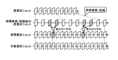
ただ、符号化対象のショットの時間長と、その参照先となるショットの時間長とは必ずしも同一ではないので、そのまま単純に差分を計算することはできない。具体的には、後者のショットを時間伸長あるいは短縮して前者に合わせ込む補正が必要である。そこで本発明では、この補正前のショットを「原類似ショット」と呼び、原類似ショットから上記補正により生成され、符号化対象となるショット(以下では「対象類似ショット」と呼ぶ)から差し引かれるショットを「参照類似ショット」と呼ぶ。図3に、「原類似ショット」「参照類似ショット」「対象類似ショット」の関係を模式的に示す。 However, since the time length of the shot to be encoded is not necessarily the same as the time length of the reference shot, the difference cannot be simply calculated as it is. Specifically, it is necessary to correct the latter shot by extending or shortening the time to match the former. Therefore, in the present invention, this pre-correction shot is referred to as an “original similar shot”, a shot generated by the above correction from the original similar shot and subtracted from a shot to be encoded (hereinafter referred to as “target similar shot”). Is referred to as a “reference similar shot”. FIG. 3 schematically shows the relationship between “original similar shot”, “reference similar shot”, and “target similar shot”.
なお、上記補正の手法にはフレーム位置の補正(フレームの補間あるいは間引き)を伴う場合と伴わない場合との下記2つが考えられるが、上記補正の手法は下記に限定されるものではない。 Note that the following two methods can be considered as the correction method, with or without frame position correction (frame interpolation or thinning), but the correction method is not limited to the following.
(原類似ショットの時間長補正・手法1)フレーム位置を補正しない場合
図4に示すように、原類似ショットのフレーム間隔を変化させる、すなわち原類似ショット中のフレームの修正をまったく行わず、単に見かけのショット時間長を変化させるだけの手法である。この手法によるショットの時間伸長/短縮処理は簡単であるが、図示するように参照類似ショットと対象類似ショットとのフレーム位置が合わないので、後続の処理ではこのずれを考慮した処理が必要となる。(Time length correction of original similar shot / method 1) When frame position is not corrected As shown in FIG. 4, the frame interval of the original similar shot is changed, that is, the frame in the original similar shot is not modified at all. This is a technique that only changes the apparent shot time length. Although the time extension / shortening process of the shot by this method is simple, the frame positions of the reference similar shot and the target similar shot do not match as shown in the figure, and the subsequent process needs to take this deviation into consideration. .
(原類似ショットの時間長補正・手法2)フレーム位置を補正する場合
図5に示すように、原類似ショットを手法1と同様に時間伸長/短縮した後、さらに対象類似ショットと同一の位置にフレームを補間する手法である。たとえば時間長補正後の原類似ショット中、対象類似ショットの対象フレームの前後に位置する2フレームを、対象フレームとの距離に応じて重み付け平均し、これを対象フレームと同一の位置に補間する。この手法は原類似ショット中の全フレームの修正を伴うので処理は複雑であるが、図示するように参照類似ショットと対象類似ショットとのフレーム位置が合っているので、後続の処理は同一位置のフレーム同士の簡単な比較となる。(Time length correction of original similar shot / method 2) When correcting frame position As shown in FIG. 5, after the original similar shot is extended / shortened in the same manner as in
なお、参照類似ショットの生成に使用する原類似ショットは、対象類似ショットに類似するショットであればどのショットであっても、またそのどの部分であってもよいが、ここではたとえば下記5つの手法を考える。また、各手法で参照類似ショットを生成したときに復号側で必要となる(従って符号化ストリームに組み込む必要がある)参照類似ショット生成情報の具体例を図6に示す。 The original similar shot used for generating the reference similar shot may be any shot or any portion as long as it is similar to the target similar shot. Here, for example, the following five methods are used. think of. FIG. 6 shows a specific example of reference similar shot generation information that is required on the decoding side when generating a reference similar shot by each method (and thus needs to be incorporated into the encoded stream).
(参照類似ショットの生成・手法1)単一の原類似ショットの全区間を使用
図3に示したように、一つの原類似ショットの全区間を時間伸長あるいは短縮して参照類似ショットを生成する手法である(図3は時間短縮の例である)。この手法を採用した場合、参照類似ショット生成情報として必要なのは、使用する原類似ショットを識別するためのID(原類似ショットID)のみである。なお、原類似ショットの伸縮率は、原類似ショットと対象類似ショットの時間比率により一意に定まる。(Generation of Reference Similar Shot / Method 1) Use All Sections of Single Original Similar Shot As shown in FIG. 3, the reference similar shot is generated by extending or shortening all sections of one original similar shot. (FIG. 3 is an example of time reduction). When this method is adopted, only the ID (original similar shot ID) for identifying the original similar shot to be used is required as the reference similar shot generation information. The expansion / contraction rate of the original similar shot is uniquely determined by the time ratio between the original similar shot and the target similar shot.
もっとも、必ずしも対象類似ショットの全区間を参照類似ショットから予測符号化しなければならないものではない。類似するショット間であっても、対応するフレーム同士がすべて類似するとは限らないので、たとえば図7に示すように対象類似ショット中、原類似ショットとのマッチングのよい区間だけについて部分的に参照類似ショットを生成するようにしてもよい。このとき対象類似ショット中、対応する参照類似ショットのない区間のフレームはそのまま符号化(すなわち、他フレームとの差を取らずにイントラ符号化)する。なお、当該区間については参照類似ショットがないと考えることもできるが、値がすべて0の参照類似ショットがあると考えることもできる。 However, it is not always necessary to predict and encode all sections of the target similar shot from the reference similar shot. Even between similar shots, the corresponding frames are not necessarily similar to each other. For example, as shown in FIG. 7, the reference similarities are partially obtained only for the sections having good matching with the original similar shots in the target similar shots. You may make it produce | generate a shot. At this time, in the target similar shot, a frame in a section having no corresponding reference similar shot is encoded as it is (that is, intra-encoding without taking a difference from other frames). In addition, although it can be considered that there is no reference similar shot in the section, it can also be considered that there is a reference similar shot whose value is all zero.
この手法を採用した場合に参照類似ショット生成情報として必要なのは、対象類似ショットのどの区間(どこからどこまで)について参照類似ショットを生成するかを指定する開始時間SRと時間長DR、および参照類似ショットの生成に使用する原類似ショットのIDである(図6参照)。上述の図3のケースは、図7において開始時間SR=対象類似ショットの先頭、時間長DR=対象類似ショットの時間長であるために、これらがなくても原類似ショットIDがあれば足りる特別の場合である。 When this method is adopted, the reference similar shot generation information requires the start time SR and the time length DR that specify which section (where from where) of the target similar shot to generate the reference similar shot, and the reference similar shot. This is the ID of the original similar shot used for generation (see FIG. 6). In the case of FIG. 3 described above, the start time SR = the head of the target similar shot and the time length DR = the time length of the target similar shot in FIG. This is the case.
(参照類似ショットの生成・手法2)単一の原類似ショットの一部区間を使用
図8に示すように、一つの原類似ショットの一部区間を時間伸長あるいは短縮して参照類似ショットを生成する手法である(図8は時間短縮の例である)。この手法を採用した場合に参照類似ショット生成情報として必要なのは、対象類似ショットのどの区間について参照類似ショットを生成するかを指定する開始時間SRと時間長DR、参照類似ショットの生成に使用する原類似ショットのID、原類似ショットのどの区間を参照類似ショットの生成に使用するかを指定する開始時間SOと時間長DOである(図6参照)。(Generation of reference similar shot / method 2) Using a part of a single original similar shot As shown in FIG. 8, a part of one original similar shot is extended or shortened to generate a reference similar shot. (FIG. 8 shows an example of time reduction). When this method is adopted, the reference similar shot generation information requires start time SR and time length DR that specify which section of the target similar shot is to generate the reference similar shot, and the source similar shot used to generate the reference similar shot. The ID of the similar shot and the start time SO and the time length DO for designating which section of the original similar shot is used to generate the reference similar shot (see FIG. 6).
(参照類似ショットの生成・手法3)複数の原類似ショットを使用
図9に示すように、複数の原類似ショットの全区間あるいは一部区間を、時間伸長あるいは短縮して参照類似ショットの一部区間を生成する手法である。図示する例では、原類似ショット1についてはその一部区間を用いて、原類似ショット2についてはその全区間を用いて、それぞれ参照類似ショットの一部が生成されている。この手法を採用した場合の参照類似ショット生成情報には、参照類似ショットを構成するそれぞれの部分(図示する例では3つ)について、上述の開始時間SRnと時間長DRn、原類似ショットID、開始時間SOnと時間長DOnが必要である(図6参照)。なお、この記述順は各部分の時間順であるのが望ましい。(Reference similar shot generation / method 3) Using a plurality of original similar shots As shown in FIG. 9, all or a part of a plurality of original similar shots are time-expanded or shortened to be a part of a reference similar shot. This is a method for generating an interval. In the illustrated example, a part of the reference similar shot is generated using the partial section for the original
(参照類似ショットの生成・手法4)複数の原類似ショットを重み付け平均して使用
図10に示すように、複数の原類似ショットの全区間あるいは一部区間を、時間伸長あるいは短縮したものをさらに重み付け平均して「平均ショット」を生成し、この「平均ショット」から参照類似ショットの全区間あるいは一部区間を生成する手法である。図示する例では、参照類似ショットの最初の部分は、原類似ショット1の一部区間を時間伸長/短縮したものと、原類似ショット2の全区間を時間伸長/短縮したものとの平均ショットから生成されている。中間部分や最後の部分も、同様に複数(必ずしも2つとは限らない)の原類似ショットの平均により生成されたものである。なお、重み付け係数は平均対象のショットごとに固定としてもよいし、フレームごとに個々に決定してもよい。また、この係数がショット間/フレーム間で等しい場合は単なる平均となるが、本発明では単なる平均も重み付け平均の一種(重み付け平均の特別な場合)として扱う。(Reference similar shot generation / method 4) Weighted average use of a plurality of original similar shots As shown in FIG. 10, all or a part of a plurality of original similar shots are further extended or shortened. In this method, an “average shot” is generated by weighted averaging, and all or a part of a reference similar shot is generated from the “average shot”. In the example shown in the figure, the first part of the reference similar shot is obtained from an average shot of a part of the original
なお、平均対象となるそれぞれのショットでフレーム位置が合っている場合は、単純に同一位置にあるフレーム間の重み付け平均を算出すればよい。一方、フレーム位置が合っていない場合は、たとえば図11に示すように各ショット中、対象類似ショットの対象フレームに時間的に最も近い2フレームを重み付け平均することで、フレーム位置が対象類似ショットと同一の平均ショットを生成し、これを参照類似ショットとする。なお、重み付け係数は平均対象のショットごとに固定としてもよいし、フレームごとに個々に決定してもよい(後者の場合、重みはたとえば上記対象フレームとの距離に応じて決定される)。 When the frame positions are the same for each shot to be averaged, a weighted average between frames at the same position may be simply calculated. On the other hand, if the frame positions do not match, for example, as shown in FIG. 11, among the shots, the two frames that are temporally closest to the target frame of the target similar shot are weighted and averaged, so that the frame position is The same average shot is generated and used as a reference similar shot. The weighting coefficient may be fixed for each average target shot or may be determined for each frame (in the latter case, the weight is determined according to the distance from the target frame, for example).
この手法を採用した場合の参照類似ショット生成情報には、参照類似ショットを構成する各部分(図示する例では3つ)について、上述の開始時間SRnと時間長DRn、そして各部分の元となるそれぞれの原類似ショットについて、そのID、開始時間SOn、時間長DOn、重み付け係数が必要である(図6参照)。なお、この手法の適応例としては具体的にはクロスフェードがあり、使用する原類似ショットやその区間を変えなくても、それぞれの重み付け係数を変えるだけで、対象類似ショットとよりよくマッチングする参照類似ショットを生成できる。 In the reference similar shot generation information when this method is adopted, the above-described start time SRn, time length DRn, and the source of each part for each part (three in the illustrated example) constituting the reference similar shot. For each original similar shot, its ID, start time SOn, time length DOn, and weighting coefficient are required (see FIG. 6). In addition, as an application example of this method, there is specifically a crossfade, and even if it does not change the original similar shot to be used and its section, it is a reference that matches better with the target similar shot only by changing each weighting coefficient Similar shots can be generated.
(参照類似ショットの生成・手法5)上記手法1〜4の組み合わせ
手法1〜4のうち最適な手法でそれぞれのショットを符号化する。この場合は参照類似ショット生成情報中に、各手法で必要な情報(上述のSRn、DRn、SOn、DOn、原類似ショットID、重み付け係数など)のほか、どの手法で参照類似ショットを生成するかを示す手法IDが必要となる(図6参照)。(Generation of Reference Similar Shot / Method 5) Combination of
そして本発明では上述のように、対象類似ショットから、上記各手法により生成された参照類似ショットを差し引いたもの(以下では「差分類似ショット」という)を符号化する。このとき、対象類似ショットと参照類似ショットのフレーム位置が合っていれば、単純に同一位置にあるフレーム間の差を取ればよいが、フレーム位置が合っていない場合は、たとえば図12に示すように、対象類似ショット中の各フレームと、参照類似フレーム中、上記各フレームに時間的に最も近いフレームとの差を取るようにする。 In the present invention, as described above, the target similar shot obtained by subtracting the reference similar shot generated by the above-described methods (hereinafter referred to as “difference similar shot”) is encoded. At this time, if the frame positions of the target similar shot and the reference similar shot match, the difference between the frames at the same position may be simply taken. If the frame positions do not match, for example, as shown in FIG. In addition, a difference between each frame in the target similar shot and a frame temporally closest to each frame in the reference similar frame is taken.
図13は、この発明の実施例1にかかる画像処理装置(エンコーダ)の構成の一例を示す説明図である。また図14は、従来技術によるJPEG/MPEGエンコーダ(動き補償なし)の構成の一例を示す説明図である。 FIG. 13 is an explanatory diagram showing an example of the configuration of the image processing apparatus (encoder) according to the first embodiment of the present invention. FIG. 14 is an explanatory diagram showing an example of the configuration of a conventional JPEG / MPEG encoder (without motion compensation).
図13中、1300〜1305は図14の同名の各部と同一である。すなわち、1300/1400は符号化対象フレーム(から参照フレームを差し引いた予測誤差)について離散コサイン変換(DCT)や離散ウェーブレット変換(DWT)などを行う変換部、1301/1401は上記変換後のデータを所定のステップ幅で量子化する量子化部、1302/1402は上記量子化後のデータなどを符号化する(その手法は特に問わない)エントロピー符号化部、1303/1403は各種符号化タイプの決定、レート制御のための量子化ステップの決定などを行う符号化制御部である。また、1304/1404は量子化後/符号化前のデータを逆量子化する逆量子化部、1305/1405は逆量子化後のデータをさらに逆変換する逆変換部である。
In FIG. 13, 1300 to 1305 are the same as the respective parts having the same names in FIG. That is, 1300/1400 is a transform unit that performs discrete cosine transform (DCT), discrete wavelet transform (DWT), etc. on the encoding target frame (prediction error obtained by subtracting the reference frame from the frame), and 1301/1401 represents the data after the transform. Quantization unit that performs quantization with a predetermined step width, 1302/1402 encodes the data after the quantization (the method is not particularly limited), and
1306は逆変換後のフレームにその参照フレームを足し合わせたもの、すなわちローカルデコード画像を少なくとも1ショット分保持する原類似ショット記憶メモリである。図14にも、ローカルデコード画像を保持するための参照フレーム記憶メモリ1406があるが、従来技術の参照フレーム記憶メモリ1406が上記画像をフレーム単位で保持するのに対し、本発明の原類似ショット記憶メモリ1306はショット単位で保持する点が違っている。なお、原類似ショット記憶メモリ1306に保持される原類似ショット数(そこに含まれる総フレーム数)は、実装上はメモリ容量により制限されるが、アルゴリズム的には制限はない。
また、1307はショット分割部であり、符号化対象となる映像を複数のショットに分割する機能部である。1308は類似ショット検出部であり、ショット分割部1307で分割された各ショット間の類似度を計算するとともに、この類似度を基礎として、上記ショットを複数のグループ(類似ショット群)に分類する機能部である。
また、1309は対象類似ショットと、原類似ショット記憶メモリ1306内の原類似ショットとを比較(マッチング)して、参照類似ショットの生成手法(対象類似ショットのどの区間について参照類似ショットを生成するか、その生成にどの原類似ショットのどの区間を使用するか、など)を決定する生成手法決定部である。理想的には最適な手法、すなわち差分類似ショットの値ができるだけ0近傍に集中するような手法を探索するが、この探索の手順などは本発明では特に問わない。評価指標としては上述の類似度のほか、カラーヒストグラム、あるいはフレーム全体のグローバル動き情報やブロック単位の動きベクトル情報などを利用できる。
また、1310は生成手法決定部1309により決定された手法に従って、原類似ショット記憶メモリ1306内の原類似ショットから参照類似ショットを生成する参照類似ショット生成部である。
A reference similar
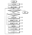
図15は、この発明の実施例1にかかる画像処理装置(エンコーダ)における、画像符号化処理の手順を示すフローチャートである。まず、符号化対象の映像をショット分割部1307で複数のショットに分割し(ステップS1501)、次に類似ショット検出部1308で各ショットの類似ショットを検出、すなわちショット間の類似度を基礎として、上記各ショットを複数のグループに分類する(ステップS1502)。
FIG. 15 is a flowchart illustrating the procedure of the image encoding process in the image processing apparatus (encoder) according to the first embodiment of the invention. First, the video to be encoded is divided into a plurality of shots by the shot division unit 1307 (step S1501), and then the similar
その後、本装置は未処理の(まだ符号化していない)ショットがある限り(ステップS1503:No)、ステップS1503〜S1510の処理を繰り返す。まず、対象類似ショットがショット内符号化、すなわち他のショットを参照しないで符号化すべきショットであるかどうかを判定する。 Thereafter, as long as there are unprocessed (not yet encoded) shots (step S1503: No), the apparatus repeats the processes of steps S1503 to S1510. First, it is determined whether or not the target similar shot is intra-shot encoding, that is, a shot to be encoded without referring to another shot.
類似する複数のショット中、少なくとも一つのショットはショット内符号化される必要がある。たとえば図1のAグループでは「A0」がこれに該当し、当該ショットについてはショット内の各フレームをそのまま変換部1300/量子化部1301で変換/量子化(ステップS1504:Yes、ステップS1508)、エントロピー符号化部1302でエントロピー符号化する(ステップS1509)。また、変換・量子化後のデータは逆量子化部1304・逆変換部1305によりローカルデコード(逆量子化および逆変換)される(ステップS1510)。
Among a plurality of similar shots, at least one shot needs to be intra-coded. For example, in the A group of FIG. 1, “A0” corresponds to this, and for each shot, each frame in the shot is directly converted / quantized by the
一方、図1の「A1」〜「A4」のように、類似する他のショットを参照するショットについては(ステップS1504:No)、まず生成手法決定部1309で参照類似ショットの生成手法を決定した後(ステップS1505)、決定された手法に従って参照類似ショット生成部1310で参照類似ショットを生成し(ステップS1506)、さらに対象類似ショットと参照類似ショットとの差、すなわち差分類似ショットを生成する(ステップS1507)。その後この差分類似ショットにつき、変換部1300/量子化部1301による変換/量子化(ステップS1508)、エントロピー符号化部1302によるエントロピー符号化(ステップS1509)、逆量子化部1304/逆変換部1305によるローカルデコード(逆量子化および逆変換)を行う(ステップS1510)。
On the other hand, as for “A1” to “A4” in FIG. 1, for a shot that refers to another similar shot (step S1504: No), first, the generation method of the reference similar shot is determined by the generation
そして、映像内の全ショットを符号化した時点で(ステップS1503:Yes)、本フローチャートによる処理を終了する。なお、生成手法決定部1309で決定された生成手法に対応する参照類似ショット生成情報(図6参照)も、エントロピー符号化部1302により符号化され、量子化部1301からのショット符号化ストリーム(各ショットの符号化データ)と多重化されて1本の符号化ストリームとなる。なお、本発明ではこの多重化の手法は特に問わない。また、ショット符号化ストリームと参照類似ショット生成情報を多重化する必要があるかどうかはアプリケーション次第であるので、これらを多重化せず、別個のストリームとして伝送するようにしてもよい。
Then, when all the shots in the video are encoded (step S1503: Yes), the processing according to this flowchart is terminated. Note that the reference similar shot generation information (see FIG. 6) corresponding to the generation method determined by the generation
なお、このように本発明では最初に対象映像全体を走査してショットの分割・分類を行うので、マルチパスによる映像符号化が可能、つまり符号化遅延が問題とされない分野での映像符号化に適している。応用例としては流通メディア(次世代光ディスクなど)の映像符号化、蓄積メディアにためたコンテンツのトランスコーディング(データ量圧縮、メモリカードへのムーブなど)が挙げられる。他にもブロードバンド・ストリーミングや録画済み(符号化済み)番組の放送用の映像符号化としても利用可能である。 In this way, in the present invention, since the entire target video is first scanned to divide and classify shots, multi-pass video encoding is possible, that is, video encoding in a field where encoding delay is not a problem. Is suitable. Examples of applications include video coding of distribution media (next-generation optical discs, etc.), transcoding of contents for storage media (data amount compression, move to memory card, etc.). In addition, it can be used for video coding for broadcasting of broadband streaming or recorded (encoded) programs.
次に、上記のようにして符号化された映像の復号について説明する。図16は、この発明の実施例1にかかる画像処理装置(デコーダ)の構成の一例を示す説明図である。図中、1600は入力した符号化ストリームを復号するとともに、復号後のショット符号化ストリームを逆量子化部1601へ、参照類似ショット生成情報を参照類似ショット生成部1604へ、それぞれ出力するエントロピー復号部である。1601はショット符号化ストリームを逆量子化する逆量子化部、1602は逆量子化後のショット符号化ストリームをさらに逆変換する逆変換部である。
Next, decoding of the video encoded as described above will be described. FIG. 16 is an explanatory diagram of an example of the configuration of the image processing apparatus (decoder) according to the first embodiment of the invention. In the figure,
1603は、復号画像を少なくとも1ショット分保持する原類似ショット記憶メモリである。1604は、エントロピー復号部1600から入力した参照類似ショット生成情報に従って、原類似ショット記憶メモリ1603内の原類似ショットから参照類似ショットを生成する参照類似ショット生成部である。
図17は、この発明の実施例1にかかる画像処理装置(デコーダ)における、画像復号処理の手順を示すフローチャートである。未処理の(まだ復号していない)ショットがある限り(ステップS1701:No)、本装置はまずエントロピー復号部1600で、符号化ストリーム中の当該ショットを復号し(ステップS1702)、さらに復号後のショットを逆量子化部1601で逆量子化、および逆変換部1602で逆変換(ステップS1703)する。
FIG. 17 is a flowchart of the image decoding process performed by the image processing apparatus (decoder) according to the first embodiment of the invention. As long as there are unprocessed (not yet decoded) shots (step S1701: No), the apparatus first uses the
その後、上記ショットがショット内符号化、すなわち他のショットを参照せずに符号化されたものであれば(ステップS1704:Yes)、上記逆変換後のデータを復号画像としてそのまま出力する(ステップS1706)。一方、上記ショットが他のショットを参照して符号化されたものであれば(ステップS1704:No)、参照類似ショット生成部1604はエントロピー復号部1600から入力した参照類似ショット生成情報に従って、原類似ショット記憶メモリ1603内の復号画像(原類似ショット)から参照類似ショットを生成する(ステップS1705)。そして、逆変換部1602からの差分類似ショットとその参照類似ショットとを加算したものが復号画像として出力される(ステップS1706)。
Thereafter, if the shot is intra-shot coded, that is, coded without referring to another shot (step S1704: Yes), the data after the inverse transformation is output as a decoded image as it is (step S1706). ). On the other hand, if the shot is encoded with reference to another shot (step S1704: No), the reference similar
さて、上述した実施例1では、対象類似ショット内の各フレームと参照類似ショット内の対応するフレームとの差を単純に計算しているが、このときフレーム間の動き補償を行えば、さらに符号効率が向上すると期待される。図18は、この発明の実施例2にかかる画像処理装置(エンコーダ)の構成の一例を示す説明図である。また、図19は従来技術によるJPEG/MPEGエンコーダ(動き補償あり)の構成の一例を示す説明図である。 In the above-described first embodiment, the difference between each frame in the target similar shot and the corresponding frame in the reference similar shot is simply calculated. Efficiency is expected to improve. FIG. 18 is an explanatory diagram of an example of the configuration of the image processing apparatus (encoder) according to the second embodiment of the present invention. FIG. 19 is an explanatory diagram showing an example of the configuration of a conventional JPEG / MPEG encoder (with motion compensation).
図18は、従来のJPEG/MPEGエンコーダの参照フレーム記憶メモリ1906を原類似ショット記憶メモリ1806に差し替えるとともに、ショット分割部1807、類似ショット検出部1808、生成手法決定部1809および参照類似ショット生成部1810を追加した構成である(上記以外の各部、すなわち変換部1800、量子化部1801、エントロピー符号化部1802、符号化制御部1803、逆量子化部1804および逆変換部1805の機能は、図19の同名の各部の機能と同一、すなわち従来技術と同一であるので説明を省略する)。あるいは図13に示した実施例1のエンコーダの構成に、フレーム間動き検出部1811とフレーム間動き補償部1812を追加したものと言うこともできる。
18 replaces the reference
なお、フレーム間動き補償予測の手法は本発明では特に問わないが、従来手法には大別して下記の2つがある。 The method of inter-frame motion compensation prediction is not particularly limited in the present invention, but the conventional methods are roughly classified into the following two.
(フレーム間動き補償予測・手法1)グローバル動き補償予測(図20)
これは参照フレーム内の四角形領域を、符号化対象フレームの矩形領域にワーピング処理(平行移動、拡大/縮小、回転、アフィン変換、透視変換など)するものである。具体的には、たとえばMPEG−4(ISO/IEC14496−2)の7.8章「Sprite decoding」がある。このグローバル動き補償予測により、フレーム全体の動きを捉えることができ、フレーム内のオブジェクトの位置ずれ/変形の修正が可能となる。(Interframe motion compensation prediction / method 1) Global motion compensation prediction (FIG. 20)
In this method, the rectangular area in the reference frame is warped (parallel movement, enlargement / reduction, rotation, affine transformation, perspective transformation, etc.) to the rectangular area of the encoding target frame. Specifically, for example, there is MPEG-8 (ISO / IEC 14496-2) chapter 7.8 “Split decoding”. By this global motion compensation prediction, it is possible to capture the motion of the entire frame, and to correct the displacement / deformation of the object in the frame.
(フレーム間動き補償予測・手法2)ブロック単位での動き補償予測(図21)
これは符号化対象フレームを正方格子状に分割し、このブロック単位で手法1と同様のワーピング処理を行うものである。ワーピング処理の一例としてたとえば平行移動の場合、個々のブロックごとに参照フレーム内で最も誤差が小さくなる領域を探索し、符号化対象フレームの各ブロックと、参照フレームの各探索結果領域の位置ずれを動きベクトルとして伝送する。このブロックの大きさはMPEG−1やMPEG−2では16×16画素(「マクロブロック」と呼ばれる)である。さらにMPEG−4では8×8画素、H.264では4×4画素の小さなブロックも許される。なお参照フレームは一つに限定されず、複数の参照フレームから最適な領域を選択するようにしてもよい。この場合は動きベクトル情報の他に、参照フレームのIDなども伝送する必要がある。このブロック単位での動き補償予測により、フレーム内の局所的なオブジェクトの動きに対応できる。(Interframe Motion Compensation Prediction / Method 2) Motion Compensation Prediction in Block Units (FIG. 21)
In this method, the encoding target frame is divided into a square lattice, and the same warping process as that in the
なお、上記のようなフレーム間動き補償予測を行う場合に、復号側で必要となる(従って符号化ストリームに組み込む必要がある)フレーム間動き情報の具体例を図22に示す。図示する例はグローバル動き予測とブロック単位での動き予測の双方を併用した例であるが、当然片方だけ使用するのでも問題はない。 FIG. 22 shows a specific example of inter-frame motion information that is necessary on the decoding side (and therefore needs to be incorporated into the encoded stream) when performing the inter-frame motion compensation prediction as described above. The illustrated example is an example in which both global motion prediction and motion prediction in units of blocks are used in combination, but there is no problem even if only one of them is used.
より具体的にフレーム間動き補償の方法を説明すると、まず対象類似ショットの各フレームと、参照類似ショットの少なくとも一つのフレームとの間でのフレーム間動き情報(たとえばアフィン変換係数や動きベクトル情報など)をフレーム間動き検出部1811で算出し、次にフレーム間動き補償部1812で、このフレーム間動き情報に従って参照類似ショットから修正参照類似ショットの各フレーム(対象類似ショットの各フレームに対する予測フレーム)を生成する。
More specifically, the inter-frame motion compensation method will be described. First, inter-frame motion information (for example, affine transformation coefficient, motion vector information, etc.) between each frame of the target similar shot and at least one frame of the reference similar shot. ) Is calculated by the inter-frame
ここで、対象類似ショットと参照類似ショットとの間でフレーム位置が合っている場合は、自然と対象類似ショットと修正参照類似ショットとの間のフレーム位置も合う。よって単純に対象類似ショット内の各フレームから、修正参照類似ショット内の同一位置にある各フレームを差し引いたものを符号化すればよい。すなわち、参照類似ショットと対象類似ショットとの類似度を動き補償予測でさらに高めることで、差分類似ショットの値がより0近傍に集中するようにする。なお、このフレーム間動き情報はショット符号化ストリームと多重化され、1本の符号化ストリームとされる。 Here, when the frame position is matched between the target similar shot and the reference similar shot, the frame position between the target similar shot and the modified reference similar shot also matches naturally. Therefore, it is only necessary to encode a frame obtained by subtracting each frame at the same position in the modified reference similar shot from each frame in the target similar shot. That is, by further increasing the similarity between the reference similar shot and the target similar shot by motion compensation prediction, the values of the difference similar shots are more concentrated in the vicinity of zero. This inter-frame motion information is multiplexed with the shot encoded stream to form one encoded stream.
一方、対象類似ショットと参照類似ショットとの間でフレーム位置が合っていない場合は、フレーム位置修正のための処理が必要となり、たとえば下記2つが考えられるが、逆に修正参照類似ショットの生成手法は下記に限定されるものではない。 On the other hand, if the frame position does not match between the target similar shot and the reference similar shot, a process for correcting the frame position is necessary. For example, the following two methods are conceivable. Is not limited to the following.
(修正参照類似ショットの生成・手法1)フレーム位置を補正しない場合
図23に示すように、対象類似ショットの各フレームと、参照類似ショット内の少なくとも一つのフレームとの間で動き検出を行う。そして得られたフレーム間動き情報により、参照類似ショットにフレーム間動き補償を行えい、修正参照類似ショットの各フレームを生成する。このとき修正参照類似ショットの各フレームの位置は参照類似ショットと同一とする(参照類似ショットのフレーム位置を保存する)ものである。この場合は修正参照類似ショット中、たとえば対象類似ショットの対象フレームに時間的に最も近いフレームと、対象フレームとの差分を符号化すればよい。(Generation /
(修正参照類似ショットの生成・手法2)フレーム位置を補正する場合
図24に示すように、手法1同様、フレーム間動き補償により修正参照類似ショットの各フレームを生成するが、同時に修正参照類似ショットの各フレームの位置を対象類似ショットと同一の位置に補正(補間あるいは間引き)するものである。この場合は対象類似ショット内の各フレームと、修正参照類似ショット内の同一位置にある各フレームとの差分を符号化すればよい。(Generation of Modified Reference Similar Shot / Method 2) When Correcting Frame Position As shown in FIG. 24, each frame of the modified reference similar shot is generated by inter-frame motion compensation as in
図25は、この発明の実施例2にかかる画像処理装置(エンコーダ)における、画像符号化処理の手順を示すフローチャートである。図15に示した実施例1の画像符号化処理との差異は、参照類似ショットの生成後(ステップS2506)に、フレーム間動き検出処理(ステップS2507)とフレーム間動き補償処理/修正参照類似ショット生成処理(ステップS2508)とが追加されている点である。そして、ステップS2508で生成された修正参照類似ショットを、対象類似ショットから差し引くことで差分類似ショットを生成する(ステップS2509)。このステップS2507〜S2509以外の各ステップ、すなわちステップS2501〜S2506およびステップS2510〜S2512における処理は、図15の同名のステップでの処理と同様である。 FIG. 25 is a flowchart illustrating the procedure of the image encoding process in the image processing apparatus (encoder) according to the second embodiment of the present invention. The difference from the image encoding process of the first embodiment shown in FIG. 15 is that, after the reference similar shot is generated (step S2506), the interframe motion detection process (step S2507) and the interframe motion compensation process / modified reference similar shot are performed. The generation process (step S2508) is added. Then, a difference similar shot is generated by subtracting the modified reference similar shot generated in step S2508 from the target similar shot (step S2509). The processes in steps other than steps S2507 to S2509, that is, steps S2501 to S2506 and steps S2510 to S2512 are the same as the processes in the steps having the same names in FIG.
次に、上記のようにして符号化された映像の復号について説明する。図26は、この発明の実施例2にかかる画像処理装置(デコーダ)の構成の一例を示す説明図である。図16に示した実施例1のデコーダとの差異は、参照類似ショット生成部2604で生成された参照類似ショットから、動き補償予測により修正参照類似ショットを生成するフレーム間動き補償部2605が追加されている点である。このフレーム間動き補償部2605以外の各部、すなわちエントロピー復号部2600、逆量子化部2601、逆変換部2602、原類似ショット記憶メモリ2603および参照類似ショット生成部2604の機能は、図16の同名の各部の機能と同一であるので説明を省略する。
Next, decoding of the video encoded as described above will be described. FIG. 26 is an explanatory diagram of an example of the configuration of the image processing device (decoder) according to the second embodiment of the present invention. The difference from the decoder of the first embodiment illustrated in FIG. 16 is that an inter-frame
また、図27はこの発明の実施例2にかかる画像処理装置(デコーダ)における、画像復号処理の手順を示すフローチャートである。図17に示した実施例1の画像復号処理との差異は、参照類似ショットの生成後(ステップS2705)に、修正参照類似ショット生成処理(ステップS2706)が追加されている点である。そして、逆変換部2602からの差分類似ショット(にフレーム間動き補償部2605からの修正参照類似ショットを足し合わせたもの)を復号画像として出力する(ステップS2707)。このステップS2706およびS2707以外の各ステップ、すなわちステップS2701〜S2705における処理は、図17の同名のステップでの処理と同様である。 FIG. 27 is a flowchart showing the procedure of the image decoding process in the image processing apparatus (decoder) according to the second embodiment of the present invention. The difference from the image decoding process of the first embodiment shown in FIG. 17 is that a modified reference similar shot generation process (step S2706) is added after the generation of the reference similar shot (step S2705). Then, the difference similar shot from the inverse transform unit 2602 (added with the modified reference similar shot from the inter-frame motion compensation unit 2605) is output as a decoded image (step S2707). Processes in steps other than steps S2706 and S2707, that is, processes in steps S2701 to S2705 are the same as the processes in the steps having the same names in FIG.
以上説明した実施例1によれば、映像内の個々のショットについて、当該ショットに類似するショットからの差分のみを符号化し、さらに実施例2ではフレームごとの動きも考慮するので、対象フレームと参照フレームとの差分は0近傍に集中することが予想され、これにより符号量を削減することができる。 According to the first embodiment described above, for each shot in the video, only the difference from a shot similar to the shot is encoded, and in the second embodiment, the movement for each frame is also considered. The difference from the frame is expected to be concentrated in the vicinity of 0, thereby reducing the code amount.
ただし、上記は符号量削減には有利に働くが、ランダムアクセス性の犠牲などのデメリットもある。たとえば図16や図26のデコーダにおいて、ある特定のショットの復号にはその参照類似ショットを必要とするので、当然その生成に使用される原類似ショットが復号されていなければならないが、当該原類似ショットを復号するにはさらにその参照類似ショットや、当該参照類似ショットの元となる原類似ショットが必要である。このように、芋蔓式に参照先を辿らなければならない事態を避けるため、映像内に定期的に参照類似ショットを使用しないショット符号化方式(ショット内符号化)を挿入することも考えられる。これはたとえばMPEGでいうIピクチャと同等の機能となる。 However, the above is advantageous for reducing the amount of codes, but has disadvantages such as sacrifice of random accessibility. For example, in the decoder of FIGS. 16 and 26, since the reference similar shot is required for decoding a specific shot, the original similar shot used for the generation must naturally be decoded. In order to decode the shot, the reference similar shot and the original similar shot that is the basis of the reference similar shot are further required. As described above, in order to avoid a situation in which the reference destination must be traced in the manner of a vine, it is also conceivable to periodically insert a shot coding method (intra-shot coding) that does not use a reference similar shot in a video. This is a function equivalent to an I picture in MPEG, for example.
なお、上述した実施例1あるいは2にかかるエンコーダは、従来技術のJPEG/MPEGエンコーダなどを利用して実現することができるが、そのためには既存のハードウェア(LSIチップなど)を作り替える必要がある。 The encoder according to the first or second embodiment described above can be realized by using a conventional JPEG / MPEG encoder or the like, but for that purpose, it is necessary to remodel existing hardware (LSI chip or the like). .
そこでたとえば図28や図29に示すように、従来技術の符号化器(エンコーダ)2800/2900に必要な機能部を外付けすることで、本発明にかかるエンコーダを実現するようにしてもよい。図28は実施例1の図13に、図29は実施例2の図18に、それぞれ対応している。具体的には符号化器2800/2900の前段に、上述の原類似ショット記憶メモリ1306/1806、ショット分割部1307/1807、類似ショット検出部1308/1808、生成手法決定部1309/1809、参照類似ショット生成部1310/1810、あるいはフレーム間動き検出部1811やフレーム間動き補償部1812を設けて、参照類似ショットあるいは修正参照類似ショット減算後の差分類似ショットを符号化器2800/2900に入力するとともに、符号化器2800/2900の後段に多重化部2801/2901を設けて、ショット符号化ストリームや参照類似ショット生成情報、フレーム間動き情報などを多重化するようにする(多重化が必要な場合)。
Therefore, for example, as shown in FIGS. 28 and 29, an encoder according to the present invention may be realized by externally attaching a function unit necessary for a conventional encoder (encoder) 2800/2900. FIG. 28 corresponds to FIG. 13 of the first embodiment, and FIG. 29 corresponds to FIG. 18 of the second embodiment. Specifically, in the preceding stage of the
図28や図29のように、参照類似ショットの生成処理を符号化ループの前に出すことで、従来の符号化器や符号化手法、たとえばMPEG−1/2/4やH.264をそのまま利用することが可能になる。ただし図示する構成のデメリットとしては、たとえば参照類似ショット生成時の動き予測と符号化時の動き予測との間の処理に冗長さが存在すること、参照類似ショットの生成と差分類似ショットの圧縮を両方考慮した符号化器の最適化が困難であることなどが挙げられる。 As shown in FIG. 28 and FIG. 29, by generating the reference similar shot generation process before the encoding loop, conventional encoders and encoding methods such as MPEG-1 / 2/4 and H.264 are used. H.264 can be used as it is. However, as a disadvantage of the illustrated configuration, for example, there is redundancy in processing between motion prediction at the time of reference similar shot generation and motion prediction at the time of encoding, generation of reference similar shot and compression of difference similar shot It is difficult to optimize the encoder considering both.
また、図30および図31は、従来技術の復号器(デコーダ)3000/3100に必要な機能部を外付けすることで、本発明にかかるデコーダを実現する例である。図30は実施例1の図16に、図31は実施例2の図26に、それぞれ対応している。具体的には復号器3000/3100の前段に分離多重化部3001/3101を設けて、入力した符号化ストリームからショット符号化ストリームや参照類似ショット生成情報、フレーム間動き情報を分離するとともに、復号器3000/3100の後段に上述の原類似ショット記憶メモリ1603/2603、参照類似ショット生成部1604/2604、あるいはフレーム間動き補償部2605を設けて、復号器3000/3100から出力されてきた差分類似ショットに参照類似ショットあるいは修正参照類似ショットを加算する。
FIG. 30 and FIG. 31 show an example in which the decoder according to the present invention is realized by externally attaching a functional unit necessary for the conventional decoder (decoder) 3000/3100. 30 corresponds to FIG. 16 of the first embodiment, and FIG. 31 corresponds to FIG. 26 of the second embodiment. Specifically, a
さて、上述した実施例2は、修正参照類似ショットの生成には原類似ショットを利用していた。ここで、さらに、実施例3では、原類似ショット以外のショットを利用することで、原類似ショットに存在しないオブジェクトの場合であっても再構成(予測)することができる。 In the second embodiment described above, the original similar shot is used to generate the modified reference similar shot. Further, in the third embodiment, by using shots other than the original similar shot, it is possible to reconstruct (predict) even an object that does not exist in the original similar shot.
具体的には、フレーム内のオブジェクトは、瞬時に出現/消失することは稀であり、通常はある時間的な幅を持ってフレーム内に存在している。従って、原類似ショットに存在しないオブジェクトは、対象類似ショット内の直前の符号化済みのフレームに存在している可能性が高い。すなわち、対象類似ショット内の直前の符号化済みのフレームを参照フレームとして選択可能とすることで、動き補償の精度が向上し、符号化のさらなる高効率化が期待される。 Specifically, the object in the frame rarely appears / disappears instantly, and usually exists in the frame with a certain temporal width. Therefore, there is a high possibility that an object that does not exist in the original similar shot exists in the previous encoded frame in the target similar shot. That is, by making it possible to select the immediately previous encoded frame in the target similar shot as a reference frame, the accuracy of motion compensation is improved, and higher efficiency of encoding is expected.
図32は、対象類似ショットを参照フレームとして利用したフレーム間予測の一手法を模式的に示す説明図である。図32に示すように、実施例3は、参照類似ショットのフレーム間予測を行う際に、原類似ショットのみならず、対象類似ショットの符号化済みフレームも参照フレームとして使用する。差分類似ショットを生成する(符号化)際には、実施例1,2同様に、参照類似ショットと対象類似ショットとの差分を求める。以下、実施例3の動き予測補償、すなわち参照フレームを選択してフレーム間動き予測補償(選択型フレーム間動き補償予測)について3種類の手法を説明する。 FIG. 32 is an explanatory diagram schematically showing a method of inter-frame prediction using a target similar shot as a reference frame. As shown in FIG. 32, when performing inter-frame prediction of a reference similar shot, Example 3 uses not only the original similar shot but also the encoded frame of the target similar shot as a reference frame. When the difference similar shot is generated (encoded), the difference between the reference similar shot and the target similar shot is obtained as in the first and second embodiments. Hereinafter, three types of methods for motion prediction compensation according to the third embodiment, that is, inter-frame motion prediction compensation (selection type inter-frame motion compensation prediction) by selecting a reference frame will be described.
(選択型フレーム間動き補償予測・手法1)原類似ショットおよび対象類似ショットを使用
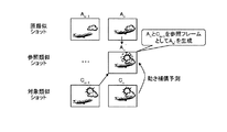
これは、符号化済みの対象類似ショットのフレームを、参照類似ショットの対象フレームとすることで、原類似ショットにないオブジェクトを予測する手法である。図33は、対象類似ショットを含めた動き補償予測の手法を模式的に示した説明図である。(Selection type inter-frame motion compensation prediction / method 1) Use original similar shot and target similar shot This is to make the original similar shot by using the frame of the encoded target similar shot as the target frame of the reference similar shot. It is a technique for predicting no objects. FIG. 33 is an explanatory diagram schematically showing a motion compensation prediction method including target similar shots.
図33において、対象類似ショットのフレームCnと、原類似ショットのフレームAnとは、ほぼ同一の類似フレームである。しかし対象類似ショットのフレームCnにある「太陽」のオブジェクトが、原類似ショットのフレームAnには存在しない。従って、原類似ショットのフレームAn、An-1のみを参照フレームとして動き予測を行った場合、この「太陽」のオブジェクトの部分の動き補償を行うことができない。結果として「太陽」のオブジェクトの部分の画質劣化あるいは符号量の増加を招くこととなる。In Figure 33, the frame C n of interest similar shots, the frame A n of the original similar shots, which is substantially the same similar frame. But in the frame C n of the target similar shots of the "sun" object does not exist in the frame A n of the original similar shots. Accordingly, when motion prediction is performed using only the frames A n and A n−1 of the original similar shot as reference frames, motion compensation cannot be performed on the “sun” object portion. As a result, the image quality of the object part of the “sun” is deteriorated or the code amount is increased.
一方、「太陽」のオブジェクト自体は、対象類似ショットの直前の符号化済みのフレームCn-1の中に存在している。よって対象類似ショットのフレームCnの参照フレームとして、原類似ショットのフレームAnだけでなく、対象類似ショットの直前の符号化済みのフレームCn-1を選択的に選ぶことにより、「太陽」のオブジェクトを含めた全体としての効果的な動き予測が可能となる。この結果得られた参照フレームAn’と対象類似ショットのフレームCnとの差分画像(差分類似ショット内のフレームに相当する)を符号化する。On the other hand, the “sun” object itself exists in the encoded frame C n−1 immediately before the target similar shot. Therefore as a reference frame of the frame C n of interest similar shots, as well as frame A n of the original similar shots, by choosing the frames C n-1 coded immediately before the target similar shots selectively, "Sun" The effective motion prediction as a whole including the object can be performed. A difference image (corresponding to a frame in the difference similar shot) between the reference frame A n ′ obtained as a result and the frame C n of the target similar shot is encoded.
なお以上の説明では参照フレームAn’を作成する際に、原類似ショットのフレームAnや対象類似ショットの直前の符号化済みのフレームCn-1の1フレームずつを選択したが、それぞれ複数のフレームを選択して予測を行ってもよい。また符号化済みフレームは時間的に前のものに限らず、MPEGにおけるBピクチャのように時間的に後のフレームを用いて動き予測を行ってもよい。このような場合、参照類似ショットの各フレームの時間順と符号順とは異なることとなる。さらに、上述のようなブロック単位での動き補償予測だけでなく、グローバル動き補償予測と組み合わせて行ってもよい。In the above description, when generating the reference frame An ′, one frame of the original similar shot frame An and the encoded frame Cn −1 immediately before the target similar shot are selected. This frame may be selected for prediction. The encoded frame is not limited to the temporally previous frame, and motion prediction may be performed using a temporally subsequent frame such as a B picture in MPEG. In such a case, the time order and the code order of each frame of the reference similar shot are different. Further, not only motion compensation prediction in units of blocks as described above, but also global motion compensation prediction may be performed.
なお、手法1において符号化に必要な情報としては、実施例2の動き予測補償に用いた情報に加えて、フレーム間動き情報内に参照フレームとして原類似ショット内のフレームを選択するか、符号化済みフレームを選択するかを識別するためのフラグや、これに参照フレームを識別する参照フレームIDを用いることができる。当然のことながら、参照フレームID自体は、フレーム識別を行う機能に加え、原類似ショット/符号化済みフレームの識別を行う機能を兼ね備えた構成のものでもよい。
As information necessary for encoding in
図34は、この発明の実施例3の選択型フレーム間動き補償予測の手法1にかかる画像処理装置(エンコーダ)の構成の一例を示す説明図である。図34のエンコーダと図18の実施例2のエンコーダとの差異は、原類似ショット記憶メモリ3406の前段に符号化ショット記憶メモリ3413を追加している点と、フレーム間動き補償部3412の前段に参照ショットセレクタ(SEL)部3414に追加している点である。従って、上記以外の各部、すなわち変換部3400、量子化部3401、エントロピー符号化部3402、符号化制御部3403、逆量子化部3404、逆変換部3405、原類似ショット記憶メモリ3406、ショット分割部3407、類似ショット検出部3408、生成手法決定部3409、参照類似ショット生成部3410、フレーム間動き検出部3411およびフレーム間動き補償部3412の機能は、図18の同名の各部の機能と同一であるので説明を省略する。
FIG. 34 is an explanatory diagram showing an example of the configuration of the image processing apparatus (encoder) according to the
なお、符号化ショット記憶メモリ3413は、参照類似ショットを生成するために、対象ショットにおける符号化済みフレームをローカルデコードしたフレームを記憶しておくためのメモリである。符号化ショット記憶メモリ3413に記憶されるフレームの数は、アプリケーションに依存する。また、符号化フレームの生成には過去のフレームだけでなく未来のフレームの使用も可能であるので、フレームの符号化順と符号化フレームの時間並びは一致しない。
The encoded
また、SEL部3414は、対象類似ショットの各フレームに対する参照フレームを、符号化済みフレーム、あるいは参照類似ショット内のフレームから選択する。
The
図35は、この発明の実施例3の選択型フレーム間動き補償予測の手法1にかかる画像処理装置(エンコーダ)における、画像符号化処理の手順を示すフローチャートである。図25に示した実施例2の画像符号化処理との差異は、ショット内符号化せずに、類似する他のショットを参照して差分類似ショットを生成する場合(ステップS3504:No)の手順として、符号化ショットと参照類似ショットのいずれかを参照フレームとして選択するための「参照フレーム選択処理」(ステップS3507)が追加されている点である。このS3507以外の各ステップ、すなわちステップS3501〜S3506およびステップS3508〜S3512における処理は、図25の同名のステップでの処理と同様である。
FIG. 35 is a flowchart showing the procedure of the image encoding process in the image processing apparatus (encoder) according to the
次に、上記のようにして符号化された映像の復号について説明する。図36は、この発明の実施例3の選択型フレーム間動き補償予測の手法1にかかる画像処理装置(デコーダ)の構成の一例を示す説明図である。図26に示した実施例2のデコーダとの差異は、原類似ショット記憶メモリ3603の前段に符号化ショット記憶メモリ3606が追加されている点と、フレーム間動き補償部3605の前段に参照フレームセレクタ(SEL)部3607が追加されている点である。この符号化ショット記憶メモリ3606およびSEL部3607以外の各部、すなわちエントロピー復号部3600、逆量子化部3601、逆変換部3602、原類似ショット記憶メモリ3603およびフレーム間動き補償部3605の機能は、図26の同名の各部の機能と同一であるので説明を省略する。
Next, decoding of the video encoded as described above will be described. FIG. 36 is an explanatory diagram showing an example of the configuration of the image processing apparatus (decoder) according to the
(選択型フレーム間動き補償予測・手法2)差分情報を使用
これは、前フレームの符号化残差、すなわち差分類似ショットを原類似ショットに加算して参照類似ショットのフレーム(FF(フィードフォワード)予測フレーム)を生成する手法である。また、動き補償予測の際には、原類似ショット、符号化済み対象類似ショットおよびFF予測フレームの中から選択的に行う。(Selection type inter-frame motion compensation prediction / method 2) Use difference information This is the frame of the reference similar shot (FF (feed forward)) by adding the encoding residual of the previous frame, that is, the difference similar shot to the original similar shot. This is a method for generating a prediction frame. In addition, the motion compensation prediction is performed selectively from the original similar shot, the encoded target similar shot, and the FF prediction frame.
図37は、符号化残差を用いたフィードフォワード予測の手法を模式的に示した説明図(その1)である。図37のように、前直のフレームの差分画像の情報(差分情報)Dn-1すなわち原類似ショットのフレームAn-1と、対象類似ショットの直前の符号化済みのフレームCn-1との差分をみると、対象類似ショットのフレームCnに存在し、原類似ショットのフレームAnには存在しない「太陽」のオブジェクトがあることがわかる。この差分情報Dn-1を、原類似ショットのフレームAnに加算した参照フレームAn’を生成する。そして、この参照フレームAn’を参照ショットとすることで、原類似ショットのフレームAnにない「太陽」のオブジェクトを含んだ参照フレームを生成することができる。すなわち、より精度の高い動き補償予測が可能となる。以下この手法を「差分画像のフィードフォワード予測」と呼び、この手法によって生成された参照フレームAn’をFF(フィードフォワード)予測フレームと呼ぶことにする。FIG. 37 is an explanatory diagram (part 1) schematically illustrating a feedforward prediction method using an encoding residual. As shown in FIG. 37, the difference image information (difference information) D n-1 of the immediately preceding frame, that is, the frame A n-1 of the original similar shot and the encoded frame C n-1 immediately before the target similar shot Looking at the difference between the, present in the frame C n of the target similar shots, it can be seen that in the frame a n of the original similar shots there is an object of does not exist, "the sun". A reference frame A n ′ is generated by adding the difference information D n−1 to the frame A n of the original similar shot. Then, by a reference shot the reference frame A n ', it is possible to generate a reference frame including the object of "Sun" is not in the frame A n of the original similar shots. That is, more accurate motion compensation prediction is possible. Hereinafter, this method is referred to as “feedforward prediction of a difference image”, and the reference frame An ′ generated by this method is referred to as an FF (feedforward) prediction frame.
図38は、符号化残差を用いたフィードフォワード予測の手法を模式的に示した説明図(その2)である。図38を用いて、図37によって説明した手法2を別の側面から説明する。図38のように原類似ショットのフレームAnとフレームAn-1の差分画像の差分(差分情報)をEnとすると、下記の(1)式が導かれる。FIG. 38 is an explanatory diagram (part 2) schematically illustrating a feedforward prediction method using an encoding residual. The method 2 described with reference to FIG. 37 will be described from another aspect with reference to FIG. As shown in FIG. 38, when the difference (difference information) between the difference images of the original similar shot frame An and frame An-1 is E n , the following equation (1) is derived.
An’=An+Dn-1=An+(Cn-1−An-1)=(An−An-1)+Cn-1
An’=An−An-1+Cn-1=Cn-1+En=An+Dn-1 …(1)A n ′ = A n + D n−1 = A n + (C n−1 −A n−1 ) = (A n −A n−1 ) + C n−1
A n ′ = A n −A n−1 + C n−1 = C n−1 + E n = A n + D n−1 (1)
従って、図37で説明した手法2における参照フレームの生成(対象類似ショットの直前の符号化済みのフレームCn-1に原類似ショットのフレーム間の差分情報Enを加算した上記FF予測フレームAn’)は、図38で説明した手法、すなわち直前の差分情報Dn-1と原類似ショットのフレームAnとを加算したものに等しいこととなる。Therefore, the FF prediction frame A to the difference information E n by adding between frames of the original similar shots generated (Frame C n-1 of the coded before the target similar shots of the reference frame in the method 2 described in FIG. 37 n ′) is equal to the method described in FIG. 38, that is, the sum of the immediately preceding difference information D n−1 and the frame A n of the original similar shot.
また、原類似ショットのフレームAn、対象類似ショットの直前の符号化済みのフレームCn-1、そして上記FF予測フレームAn’から最適な参照フレームを選択するようにしてもよい。さらに上記のブロック単位での動き補償予測だけでなく、グローバル動き補償予測と組み合わせてもよい。ここで符号化に必要な情報としては、予測手法識別フラグ(原類似ショット/符号化済みフレーム/FF予測フレーム)、参照フレームを識別する参照フレームID、動きベクトル情報などであり、各情報は、符号化対象フレーム内のすべてのブロックについて記述される。Further, an optimal reference frame may be selected from the frame A n of the original similar shot, the encoded frame C n−1 immediately before the target similar shot, and the FF predicted frame An ′. Furthermore, not only the motion compensation prediction in units of blocks described above but also global motion compensation prediction may be combined. Here, information necessary for encoding includes a prediction method identification flag (original similar shot / encoded frame / FF prediction frame), a reference frame ID for identifying a reference frame, motion vector information, and the like. All blocks in the encoding target frame are described.
図39は、この発明の実施例3の選択型フレーム間動き補償予測の手法2にかかる画像処理装置(エンコーダ)の構成の一例を示す説明図である。図39のエンコーダと図34の実施例3の手法1のエンコーダとの差異は、符号化済みフレームと参照類似ショット内のフレームから、フィードフォワード予測フレーム(以下、「FF予測フレーム」という)を生成するFF予測フレーム生成部3915を追加した点である。セレクタ(SEL)部3914には、符号化済みフレームと、参照類似ショット内のフレームと、FF予測フレームとが入力される。従って、上記以外の各部、すなわち変換部3900、量子化部3901、エントロピー符号化部3902、符号化制御部3903、逆量子化部3904、逆変換部3905、原類似ショット記憶メモリ3906、ショット分割部3907、類似ショット検出部3908、生成手法決定部3909、参照類似ショット生成部3910、フレーム間動き検出部3911、フレーム間動き補償部3912、符号化ショット記憶メモリ3913およびセレクタ(SEL)部3914の機能は、図34の同名の各部の機能と同一であるので説明を省略する。
FIG. 39 is an explanatory diagram showing an example of the configuration of the image processing apparatus (encoder) according to the method 2 of the selective interframe motion compensation prediction according to the third embodiment of the present invention. The difference between the encoder of FIG. 39 and the encoder of
図40は、この発明の実施例3の選択型フレーム間動き補償予測の手法2にかかる画像処理装置(エンコーダ)における、画像符号化処理の手順を示すフローチャートである。図35に示した実施例3の手法1の画像符号化処理との差異は、ショット内符号化せずに、類似する他のショットを参照して差分類似ショットを生成する場合(ステップS4004:No)の手順として、差分画像のFF予測画像生成処理(ステップS4007)が追加されている点である。また参照フレーム選択(ステップS4008)では、符号化ショット、参照類似ショット、あるいはFF予測画像から最適な参照フレームを選択する。このステップS4007,S4007以外の各ステップ、すなわちステップS4001〜S4006およびステップS4009〜S4014における処理は、図35の同名のステップでの処理と同様である。
FIG. 40 is a flowchart showing the procedure of the image encoding process in the image processing apparatus (encoder) according to the method 2 of the selective interframe motion compensation prediction according to the third embodiment of the present invention. The difference from the image coding process of the
次に、上記のようにして符号化された映像の復号について説明する。図41は、この発明の実施例3の選択型フレーム間動き補償予測の手法2にかかる画像処理装置(デコーダ)の構成の一例を示す説明図である。図36に示した実施例3の手法1のデコーダとの差異は、符号化済みフレームと原類似ショット内のフレームとからFF予測フレームを生成するFF予測フレーム生成部4108を追加した点である。このFF予測フレーム生成部4108以外の各部、すなわちエントロピー復号部4100、逆量子化部4101、逆変換部4102、原類似ショット記憶メモリ4103、参照類似ショット生成部4104、フレーム間動き補償部4105、符号化ショット記憶メモリ4106および参照フレーム選択(SEL)部4107の機能は、図36の同名の各部の機能と同一であるので説明を省略する。
Next, decoding of the video encoded as described above will be described. FIG. 41 is an explanatory diagram showing an example of the configuration of the image processing device (decoder) according to the method 2 of the selective interframe motion compensation prediction according to the third embodiment of the present invention. A difference from the decoder of the
(選択型フレーム間動き補償予測・手法3)
これは、原類似ショットの動き情報を対象類似ショットに適用する手法であり、動きベクトル情報の削減を目的とし、結果として符号化効率の改善を実現する。図42は、原類似ショットの動き情報を用いたフィードフォワード予測の手法を模式的に示した説明図である。なお、ここでは、ある2つのフレームFn-1,Fn間の動き情報をM(Fn-1,Fn)と表記する。またフレームFn-1に動き情報M(Fn-1,Fn)によって動き補償を行い生成されるフレームをFn-1*M(Fn-1,Fn)と表記する。(Selection type interframe motion compensation prediction / method 3)
This is a method of applying the motion information of the original similar shot to the target similar shot, aiming at reduction of motion vector information, and as a result, improving the coding efficiency. FIG. 42 is an explanatory diagram schematically showing a feedforward prediction method using motion information of the original similar shot. Here, the motion information between two frames F n−1 and F n is expressed as M (F n−1 , F n ). A frame generated by performing motion compensation on the frame F n-1 using the motion information M (F n−1 , F n ) is denoted as F n−1 * M (F n−1 , F n ).
もし原類似ショットと対象類似ショットの動きがまったく同一ならば、下記(2)式のように、原類似ショットのフレームAn-1,An間の動き情報Mと、相当する対象類似ショットのフレームCn-1,Cn間の動き情報Mが同一であると仮定できる。If If the raw similar shot and the target similar shots movement exactly identical, as in the following equation (2), the motion information M inter-frame A n-1, A n of the original similar shots, the subject analogs shot corresponding It can be assumed that the motion information M between the frames C n-1 and C n is the same.
M(An-1,An)=M(Cn-1,Cn) …(2)M (A n−1 , A n ) = M (C n−1 , C n ) (2)
すなわち、下記(3)式のように原類似ショットの動き情報M(An-1,An)を、対象類似ショットの相当するフレーム(たとえば、Cn-1)に用いれば、同様に動き補償予測を行うことができる。That is, if the motion information M (A n−1 , A n ) of the original similar shot is used for the frame (for example, C n−1 ) corresponding to the target similar shot, Compensated prediction can be performed.
Cn=Cn-1*M(An-1,An) …(3)Cn = Cn -1 * M ( An-1 , An ) (3)
また原類似ショットと対象類似ショットの動きがまったく同一でないが酷似していると考えられる場合は、上記の(3)式で生成されるフレームは、対象類似ショットのフレームCnに類似していると想定される。従って下記(4)式によって生成される参照フレームAn’と対象類似ショットのフレームCnとの間で動き補償予測によって得られる動き情報M(An’,Cn)は小さい値のみを取ることが期待でき、結果として符号量の削減が実現できる。When the movements of the original similar shot and the target similar shot are not exactly the same but are considered to be very similar, the frame generated by the above equation (3) is similar to the frame C n of the target similar shot. It is assumed. Accordingly, the motion information M (A n ′, C n ) obtained by motion compensation prediction between the reference frame A n ′ generated by the following equation (4) and the frame C n of the target similar shot takes only a small value. As a result, the amount of code can be reduced.
An’=Cn-1*M(An-1,An) …(4)A n ′ = C n−1 * M (A n−1 , A n ) (4)
なお、動き情報Mとしては、ブロック単位での動きベクトルのみならず、画面全体の動きを表すグローバル動き情報のどちらでもよく、またこれら両方の使用でもよい。ここで符号化に必要な情報としては、フィードフォワード予測使用フラグ(FF予測を使用する/しないを表すフラグ)、動きベクトル情報などがあり、各情報は、符号化対象フレーム内のすべてのブロックについて記述される。また、FF予測使用時の参照フレームは、原類似ショットの動き補償での参照フレームとの対応で一意に決まる。 The motion information M may be not only a motion vector in units of blocks, but also global motion information representing the motion of the entire screen, or both of them may be used. Here, information necessary for encoding includes a feedforward prediction use flag (a flag indicating whether or not to use FF prediction), motion vector information, and the like. Each information is for all blocks in the encoding target frame. Described. In addition, the reference frame when using the FF prediction is uniquely determined by the correspondence with the reference frame in motion compensation of the original similar shot.
図43は、この発明の実施例3の選択型フレーム間動き補償予測の手法3にかかる画像処理装置(エンコーダ)の構成の一例を示す説明図である。図43のエンコーダと図34の実施例3の手法1のエンコーダとの差異は、原類似ショットのフレーム間動き情報Mを記憶しておく原類似ショット動き情報記憶メモリ4315と、符号化済みフレームに、原類似ショットの動き情報Mを用いて動き補償を行うFF動き補償部4316とを追加した点である。セレクタ(SEL)部4314には、符号化済みフレームと、FF動き補償されたフレームとが入力される。従って、上記以外の各部、すなわち変換部4300、量子化部4301、エントロピー符号化部4302、符号化制御部4303、逆量子化部4304、逆変換部4305、ショット分割部4307、類似ショット検出部4308、フレーム間動き検出部4311、フレーム間動き補償部4312、符号化ショット記憶メモリ4313およびセレクタ(SEL)部4314の機能は、図34の同名の各部の機能と同一であるので説明を省略する。
FIG. 43 is an explanatory diagram showing an example of the configuration of the image processing device (encoder) according to the method 3 of the selective interframe motion compensation prediction according to the third embodiment of the present invention. The difference between the encoder of FIG. 43 and the encoder of the
図44は、この発明の実施例3の選択型フレーム間動き補償予測の手法3にかかる画像処理装置(エンコーダ)における、画像符号化処理の手順を示すフローチャートである。図35に示した実施例3の手法1の画像符号化処理との差異は、ショット内符号化せずに、類似する他のショットを参照して差分類似ショットを生成する場合(ステップS4404:No)の手順として、図35のステップS3505〜S3507の処理に替えて動き情報MのFF動き補償予測処理(ステップS4405)が追加されている点である。そして、ステップS4007で生成された修正参照類似ショットを、対象類似ショットから差し引くことで差分類似ショットを生成する(ステップS4408)。このステップS4405以外の各ステップ、すなわちステップS4401〜S4404における処理は、図35の同名のステップでの処理と同様であり、ステップS4406〜S4411における処理は、図35のステップS3508〜S3513の同名のステップでの処理と同様である。
FIG. 44 is a flowchart showing the procedure of the image encoding process in the image processing apparatus (encoder) according to the method 3 of the selective interframe motion compensation prediction according to the third embodiment of the present invention. The difference from the image coding process of the
次に、上記のようにして符号化された映像の復号について説明する。図45は、この発明の実施例3の選択型フレーム間動き補償予測の手法3にかかる画像処理装置(デコーダ)の構成の一例を示す説明図である。図36に示した実施例3の手法1のデコーダとの差異は、原類似ショットのフレーム間の動き情報Mを記憶しておく原類似ショット動き情報記憶メモリ4315と、符号化済みフレームに、原類似ショットの動き情報Mを用いて動き補償を行うFF動き補償部4316とを追加した点である。この原類似ショット動き情報記憶メモリ4315およびFF動き補償部4316以外の各部、すなわちエントロピー復号部4500、逆量子化部4501、逆変換部4502、フレーム間動き補償部4505、符号化ショット記憶メモリ4506および参照フレーム選択(SEL)部4507の機能は、図36の同名の各部の機能と同一であるので説明を省略する。
Next, decoding of the video encoded as described above will be described. FIG. 45 is an explanatory diagram showing an example of the configuration of the image processing device (decoder) according to the method 3 of the selective interframe motion compensation prediction according to the third embodiment of the present invention. 36 differs from the decoder of the
このように、請求項1〜請求項3、請求項7〜請求項9、請求項13に記載の発明によれば、符号化対象の映像を構成する複数のショットの類似性(情報の冗長性)に着目して、類似するフレーム同士の差分を符号化するので、符号化ストリームのデータ量を抑制できる。また、類似するフレーム間でさらに動き補償を行うので、フレーム内でのオブジェクトの位置ずれ/変形を修正し、両フレームの差分をより0近傍に集中させることができる(従って符号化ストリームのデータ量をさらに抑制できる)。
Thus, according to the inventions of
また、請求項4〜請求項6、請求項10〜請求項12、請求項13に記載の発明によれば、請求項1〜請求項3、請求項7〜請求項9、あるいは請求項13に記載の発明により符号化された動画像を復号できる。 In addition, according to the inventions of claims 4 to 6, claims 10 to 12, and claim 13, claims 1 to 3, claims 7 to 9, or claim 13. A moving image encoded by the described invention can be decoded.
なお、本実施の形態で説明した画像処理方法は、あらかじめ用意されたプログラムをプロセッサやマイクロコンピュータ等の演算処理装置で実行することにより実現することができる。このプログラムは、ROM、HD、FD、CD−ROM、CD−R、CD−RW、MO、DVD等の演算処理装置で読み取り可能な記録媒体に記録され、演算処理装置によって記録媒体から読み出されて実行される。またこのプログラムは、インターネット等のネットワークを介して配布することが可能な伝送媒体であってもよい。 The image processing method described in this embodiment can be realized by executing a program prepared in advance by an arithmetic processing device such as a processor or a microcomputer. This program is recorded on a recording medium readable by an arithmetic processing device such as ROM, HD, FD, CD-ROM, CD-R, CD-RW, MO, DVD, etc., and read from the recording medium by the arithmetic processing device. Executed. The program may be a transmission medium that can be distributed via a network such as the Internet.
Claims (9)
前記ショット分割手段により分割されたショットの中から符号化対象となる第1のショットに類似する第2のショットを検出するショット検出手段と、
前記ショット検出手段により検出された第2のショットの時間長を補正して第3のショットを生成する第1のショット生成手段と、
前記第1のショットおよび前記第3のショットの少なくともいずれか一つを用いて動き補償して第4のショットを生成する第2のショット生成手段と、
前記第1のショットと前記第2のショット生成手段により生成された第4のショットとの差分を符号化する符号化手段と、
を備えることを特徴とする画像処理装置。Shot dividing means for dividing a moving image into a plurality of shots composed of a plurality of continuous frames;
Shot detecting means for detecting a second shot similar to the first shot to be encoded from the shots divided by the shot dividing means;
First shot generating means for correcting the time length of the second shot detected by the shot detecting means to generate a third shot;
Second shot generation means for generating a fourth shot by performing motion compensation using at least one of the first shot and the third shot;
Encoding means for encoding a difference between the first shot and the fourth shot generated by the second shot generating means;
An image processing apparatus comprising:
前記ショット分割手段により分割されたショットの中から符号化対象となる第1のショットに類似する第2のショットを検出するショット検出手段と、
前記ショット検出手段により検出された第2のショットの時間長を補正して第3のショットを生成する第1のショット生成手段と、
前記第1のショットと前記第3のショット内のフレームの差分情報とを用いて第4のショットを生成する第2のショット生成手段と、
前記第4のショットを用いて動き補償して第5のショットを生成する第3のショット生成手段と、
前記第1のショットと前記第3のショット生成手段により生成された第5のショットとの差分を符号化する符号化手段と、
を備えることを特徴とする画像処理装置。Shot dividing means for dividing a moving image into a plurality of shots composed of a plurality of continuous frames;
Shot detecting means for detecting a second shot similar to the first shot to be encoded from the shots divided by the shot dividing means;
First shot generating means for correcting the time length of the second shot detected by the shot detecting means to generate a third shot;
Second shot generation means for generating a fourth shot using difference information of frames in the first shot and the third shot;
Third shot generating means for generating a fifth shot by performing motion compensation using the fourth shot;
Encoding means for encoding a difference between the first shot and the fifth shot generated by the third shot generating means;
An image processing apparatus comprising:
前記動画像の符号化データ中のショット生成情報で特定される手法により、前記第1のショットに類似する前記動画像中の第2のショットの時間長を補正して第3のショットを生成する第1のショット生成手段と、
前記ショット復号手段により復号された符号化データおよび前記第3のショットの少なくともいずれか一つを用いて動き補償して第4のショットを生成する第2のショット生成手段と、
前記ショット復号手段により復号された符号化データと前記第2のショット生成手段により生成された第4のショットとを加算するショット加算手段と、
を備えることを特徴とする画像処理装置。Shot decoding means for decoding the encoded data of the first shot consisting of a plurality of consecutive frames in the encoded data of the moving image;
The third shot is generated by correcting the time length of the second shot in the moving image similar to the first shot by the method specified by the shot generation information in the encoded data of the moving image. First shot generation means;
Second shot generation means for generating a fourth shot by performing motion compensation using at least one of the encoded data decoded by the shot decoding means and the third shot;
Shot addition means for adding the encoded data decoded by the shot decoding means and the fourth shot generated by the second shot generation means;
An image processing apparatus comprising:
前記動画像の符号化データ中のショット生成情報で特定される手法により、前記第1のショットに類似する前記動画像中の第2のショットの時間長を補正して第3のショットを生成する第1のショット生成手段と、
前記第1のショットと前記第3のショット内のフレームの差分情報とを用いて第4のショットを生成する第2のショット生成手段と、
前記第4のショットを動き補償して第5のショットを生成する第3のショット生成手段と、
前記ショット復号手段により復号された符号化データと前記第3のショット生成手段により生成された第5のショットとを加算するショット加算手段と、
を備えることを特徴とする画像処理装置。Shot decoding means for decoding the encoded data of the first shot consisting of a plurality of consecutive frames in the encoded data of the moving image;
The third shot is generated by correcting the time length of the second shot in the moving image similar to the first shot by the method specified by the shot generation information in the encoded data of the moving image. First shot generation means;
Second shot generation means for generating a fourth shot using difference information of frames in the first shot and the third shot;
Third shot generation means for generating a fifth shot by motion compensation of the fourth shot;
Shot addition means for adding the encoded data decoded by the shot decoding means and the fifth shot generated by the third shot generation means;
An image processing apparatus comprising:
前記ショット分割工程で分割されたショットの中から符号化対象となる第1のショットに類似する第2のショットを検出するショット検出工程と、
前記ショット検出工程で検出された第2のショットの時間長を補正して第3のショットを生成する第1のショット生成工程と、
前記第1のショットおよび前記第3のショットの少なくともいずれか一つを用いて動き補償して第4のショットを生成する第2のショット生成工程と、
前記第1のショットと前記第2のショット生成工程で生成された第4のショットとの差分を符号化する符号化工程と、
を含むことを特徴とする画像処理方法。A shot dividing step of dividing a moving image into a plurality of shots composed of a plurality of continuous frames;
A shot detection step of detecting a second shot similar to the first shot to be encoded from the shots divided in the shot division step;
A first shot generation step of generating a third shot by correcting the time length of the second shot detected in the shot detection step;
A second shot generating step of generating a fourth shot by performing motion compensation using at least one of the first shot and the third shot;
An encoding step for encoding a difference between the first shot and the fourth shot generated in the second shot generation step;
An image processing method comprising:
前記ショット分割工程で分割されたショットの中から符号化対象となる第1のショットに類似する第2のショットを検出するショット検出工程と、
前記ショット検出工程で検出された第2のショットの時間長を補正して第3のショットを生成する第1のショット生成工程と、
前記第1のショットと前記第3のショット内のフレームの差分情報とを用いて第4のショットを生成する第2のショット生成工程と、
前記第4のショットを動き補償して第5のショットを生成する第3のショット生成工程と、
前記第1のショットと前記第3のショット生成工程で生成された第5のショットとの差分を符号化する符号化工程と、
を含むことを特徴とする画像処理方法。A shot dividing step of dividing a moving image into a plurality of shots composed of a plurality of continuous frames;
A shot detection step of detecting a second shot similar to the first shot to be encoded from the shots divided in the shot division step;
A first shot generation step of generating a third shot by correcting the time length of the second shot detected in the shot detection step;
A second shot generating step of generating a fourth shot using difference information of the frames in the first shot and the third shot;
A third shot generating step of generating a fifth shot by motion compensation of the fourth shot;
An encoding step for encoding a difference between the first shot and the fifth shot generated in the third shot generation step;
An image processing method comprising:
前記動画像の符号化データ中のショット生成情報で特定される手法により、前記第1のショットに類似する前記動画像中の第2のショットの時間長を補正して第3のショットを生成する第1のショット生成工程と、
前記ショット復号工程により復号された符号化データおよび前記第3のショットの少なくともいずれか一つを用いて動き補償して第4のショットを生成する第2のショット生成工程と、
前記ショット復号工程で復号された符号化データと前記第2のショット生成工程で生成された第4のショットとを加算するショット加算工程と、
を含むことを特徴とする画像処理方法。A shot decoding step of decoding encoded data of a first shot consisting of a plurality of consecutive frames in the encoded data of the moving image;
The third shot is generated by correcting the time length of the second shot in the moving image similar to the first shot by the method specified by the shot generation information in the encoded data of the moving image. A first shot generating step;
A second shot generating step of generating a fourth shot by performing motion compensation using at least one of the encoded data decoded by the shot decoding step and the third shot;
A shot addition step of adding the encoded data decoded in the shot decoding step and the fourth shot generated in the second shot generation step;
An image processing method comprising:
前記動画像の符号化データ中のショット生成情報で特定される手法により、前記第1のショットに類似する前記動画像中の第2のショットの時間長を補正して第3のショットを生成する第1のショット生成工程と、
前記第1のショットと前記第3のショット内のフレームの差分情報とを用いて第4のショットを生成する第2のショット生成工程と、
前記第4のショットを動き補償して第5のショットを生成する第3のショット生成工程と、
前記ショット復号工程で復号された符号化データと前記第3のショット生成工程で生成された第5のショットとを加算するショット加算工程と、
を含むことを特徴とする画像処理方法。A shot decoding step of decoding encoded data of a first shot consisting of a plurality of consecutive frames in the encoded data of the moving image;
The third shot is generated by correcting the time length of the second shot in the moving image similar to the first shot by the method specified by the shot generation information in the encoded data of the moving image. A first shot generating step;
A second shot generating step of generating a fourth shot using difference information of the frames in the first shot and the third shot;
A third shot generating step of generating a fifth shot by motion compensation of the fourth shot;
A shot addition step of adding the encoded data decoded in the shot decoding step and the fifth shot generated in the third shot generation step;
An image processing method comprising:
Priority Applications (1)
| Application Number | Priority Date | Filing Date | Title |
|---|---|---|---|
| JP2008503875A JP4866417B2 (en) | 2006-03-09 | 2007-03-06 | Image processing apparatus, image processing method, and image processing program |
Applications Claiming Priority (4)
| Application Number | Priority Date | Filing Date | Title |
|---|---|---|---|
| JP2006064509 | 2006-03-09 | ||
| JP2006064509 | 2006-03-09 | ||
| JP2008503875A JP4866417B2 (en) | 2006-03-09 | 2007-03-06 | Image processing apparatus, image processing method, and image processing program |
| PCT/JP2007/054343 WO2007102511A1 (en) | 2006-03-09 | 2007-03-06 | Video image processing device, video image processing method, and video image processing program |
Publications (2)
| Publication Number | Publication Date |
|---|---|
| JPWO2007102511A1 JPWO2007102511A1 (en) | 2009-07-23 |
| JP4866417B2 true JP4866417B2 (en) | 2012-02-01 |
Family
ID=38474938
Family Applications (1)
| Application Number | Title | Priority Date | Filing Date |
|---|---|---|---|
| JP2008503875A Expired - Fee Related JP4866417B2 (en) | 2006-03-09 | 2007-03-06 | Image processing apparatus, image processing method, and image processing program |
Country Status (3)
| Country | Link |
|---|---|
| US (1) | US8139877B2 (en) |
| JP (1) | JP4866417B2 (en) |
| WO (1) | WO2007102511A1 (en) |
Families Citing this family (10)
| Publication number | Priority date | Publication date | Assignee | Title |
|---|---|---|---|---|
| WO2007102511A1 (en) * | 2006-03-09 | 2007-09-13 | Pioneer Corporation | Video image processing device, video image processing method, and video image processing program |
| JP4631879B2 (en) * | 2007-07-25 | 2011-02-16 | ソニー株式会社 | Encoding processing device |
| JP4539755B2 (en) * | 2008-04-11 | 2010-09-08 | ソニー株式会社 | Information processing system, information processing method, and program |
| US20100165123A1 (en) * | 2008-12-29 | 2010-07-01 | Microsoft Corporation | Data-Driven Video Stabilization |
| US8805862B2 (en) * | 2009-08-18 | 2014-08-12 | Industrial Technology Research Institute | Video search method using motion vectors and apparatus thereof |
| US8515933B2 (en) * | 2009-08-18 | 2013-08-20 | Industrial Technology Research Institute | Video search method, video search system, and method thereof for establishing video database |
| TWI443535B (en) * | 2010-12-01 | 2014-07-01 | Ind Tech Res Inst | Video search method, system, and method for establishing a database therefor |
| KR101611437B1 (en) * | 2009-10-28 | 2016-04-26 | 삼성전자주식회사 | Method and apparatus for encoding/decoding image by referencing to a plurality of frames |
| WO2013129585A1 (en) * | 2012-02-29 | 2013-09-06 | 三菱電機株式会社 | Image encoding device, image decoding device, image encoding method, and image decoding method |
| US8818037B2 (en) | 2012-10-01 | 2014-08-26 | Microsoft Corporation | Video scene detection |
Citations (7)
| Publication number | Priority date | Publication date | Assignee | Title |
|---|---|---|---|---|
| JPH07193748A (en) * | 1993-12-27 | 1995-07-28 | Nippon Telegr & Teleph Corp <Ntt> | Method and device for processing moving image |
| JPH09187015A (en) * | 1995-11-02 | 1997-07-15 | Mitsubishi Electric Corp | Image encoder and decoder |
| JPH10257436A (en) * | 1997-03-10 | 1998-09-25 | Atsushi Matsushita | Automatic hierarchical structuring method for moving image and browsing method using the same |
| JP2002271798A (en) * | 2001-03-08 | 2002-09-20 | Matsushita Electric Ind Co Ltd | Data encoder and data decoder |
| JP2003333602A (en) * | 2002-05-03 | 2003-11-21 | Lg Electronics Inc | Method for coding moving picture |
| JP2006020330A (en) * | 2004-07-01 | 2006-01-19 | Thomson Licensing | Process and device for compressing video documents |
| WO2006028156A1 (en) * | 2004-09-10 | 2006-03-16 | Pioneer Corporation | Image processing apparatus, image processing method and image processing program |
Family Cites Families (13)
| Publication number | Priority date | Publication date | Assignee | Title |
|---|---|---|---|---|
| JPH08186789A (en) | 1994-12-28 | 1996-07-16 | Canon Inc | Editing method and device for dynamic image data |
| US6049362A (en) * | 1996-02-14 | 2000-04-11 | International Business Machines Corporation | Dual prime motion estimation system and method |
| US5768537A (en) * | 1996-02-22 | 1998-06-16 | International Business Machines Corporation | Scalable MPEG2 compliant video encoder |
| US5661524A (en) * | 1996-03-08 | 1997-08-26 | International Business Machines Corporation | Method and apparatus for motion estimation using trajectory in a digital video encoder |
| JP3423834B2 (en) | 1996-04-26 | 2003-07-07 | 日本電信電話株式会社 | Predictive coded image data management method and apparatus |
| JP3764488B2 (en) * | 1997-06-03 | 2006-04-05 | 株式会社日立製作所 | Image encoding and decoding method and apparatus |
| US6252905B1 (en) * | 1998-02-05 | 2001-06-26 | International Business Machines Corporation | Real-time evaluation of compressed picture quality within a digital video encoder |
| US6831948B1 (en) * | 1999-07-30 | 2004-12-14 | Koninklijke Philips Electronics N.V. | System and method for motion compensation of image planes in color sequential displays |
| JP2001054106A (en) | 1999-08-06 | 2001-02-23 | Matsushita Electric Ind Co Ltd | Method and device for recording and reproducing video data |
| JP2002185969A (en) | 2000-10-02 | 2002-06-28 | Toshiba Corp | Method and device for format transformation of moving image encoding data |
| US7113543B2 (en) * | 2003-02-03 | 2006-09-26 | Texas Instruments Incorporated | Video encoding |
| US7602851B2 (en) * | 2003-07-18 | 2009-10-13 | Microsoft Corporation | Intelligent differential quantization of video coding |
| WO2007102511A1 (en) * | 2006-03-09 | 2007-09-13 | Pioneer Corporation | Video image processing device, video image processing method, and video image processing program |
-
2007
- 2007-03-06 WO PCT/JP2007/054343 patent/WO2007102511A1/en active Application Filing
- 2007-03-06 US US12/282,083 patent/US8139877B2/en not_active Expired - Fee Related
- 2007-03-06 JP JP2008503875A patent/JP4866417B2/en not_active Expired - Fee Related
Patent Citations (7)
| Publication number | Priority date | Publication date | Assignee | Title |
|---|---|---|---|---|
| JPH07193748A (en) * | 1993-12-27 | 1995-07-28 | Nippon Telegr & Teleph Corp <Ntt> | Method and device for processing moving image |
| JPH09187015A (en) * | 1995-11-02 | 1997-07-15 | Mitsubishi Electric Corp | Image encoder and decoder |
| JPH10257436A (en) * | 1997-03-10 | 1998-09-25 | Atsushi Matsushita | Automatic hierarchical structuring method for moving image and browsing method using the same |
| JP2002271798A (en) * | 2001-03-08 | 2002-09-20 | Matsushita Electric Ind Co Ltd | Data encoder and data decoder |
| JP2003333602A (en) * | 2002-05-03 | 2003-11-21 | Lg Electronics Inc | Method for coding moving picture |
| JP2006020330A (en) * | 2004-07-01 | 2006-01-19 | Thomson Licensing | Process and device for compressing video documents |
| WO2006028156A1 (en) * | 2004-09-10 | 2006-03-16 | Pioneer Corporation | Image processing apparatus, image processing method and image processing program |
Also Published As
| Publication number | Publication date |
|---|---|
| WO2007102511A1 (en) | 2007-09-13 |
| US20090086034A1 (en) | 2009-04-02 |
| US8139877B2 (en) | 2012-03-20 |
| JPWO2007102511A1 (en) | 2009-07-23 |
Similar Documents
| Publication | Publication Date | Title |
|---|---|---|
| JP4866417B2 (en) | Image processing apparatus, image processing method, and image processing program | |
| JP4465362B2 (en) | Image processing apparatus, image processing method, and image processing program | |
| JP3939551B2 (en) | Moving image processing apparatus, method thereof, and recording medium | |
| US8824553B2 (en) | Video compression method | |
| EP1147668B1 (en) | Improved motion estimation and block matching pattern | |
| US6421385B1 (en) | Apparatus and method for efficient conversion of DV (digital video) format encoded video data into MPEG format encoded video data by utilizing motion flag information contained in the DV data | |
| US8290288B2 (en) | Encoding macroblock type and coded block pattern information | |
| US7242814B2 (en) | Signal encoding method and apparatus and decoding method and apparatus | |
| US8804825B2 (en) | Bi-pred mode decision in GOP architecture | |
| US20070297510A1 (en) | Method and Apparatus for Generating Coded Picture Data and for Decoding Coded Picture Data | |
| US20080159398A1 (en) | Decoding Method and Coding Method | |
| US11758179B2 (en) | Image encoding method, image encoding device, image decoding method, and image decoding device | |
| KR20070007295A (en) | Video encoding method and apparatus | |
| WO2006035883A1 (en) | Image processing device, image processing method, and image processing program | |
| EP1089280A2 (en) | Method of indexing and searching moving picture data using a motion activity description method | |
| JP4574444B2 (en) | Image decoding apparatus and method, image encoding apparatus and method, computer program, and storage medium | |
| JP2868445B2 (en) | Moving image compression method and apparatus | |
| US6898244B1 (en) | Movement vector generating apparatus and method and image encoding apparatus and method | |
| JP6181242B2 (en) | Image decoding method | |
| JP5951915B2 (en) | Image decoding method | |
| JP5911982B2 (en) | Image decoding method | |
| JP2006311078A (en) | High efficiency coding recorder | |
| JP5946980B1 (en) | Image decoding method | |
| JP5750191B2 (en) | Image decoding method | |
| JP2010041408A (en) | Moving image encoding apparatus, moving image decoding apparatus, moving image encoding method and moving image decoding method |
Legal Events
| Date | Code | Title | Description |
|---|---|---|---|
| A131 | Notification of reasons for refusal |
Free format text: JAPANESE INTERMEDIATE CODE: A131 Effective date: 20110517 |
|
| A521 | Request for written amendment filed |
Free format text: JAPANESE INTERMEDIATE CODE: A523 Effective date: 20110627 |
|
| A131 | Notification of reasons for refusal |
Free format text: JAPANESE INTERMEDIATE CODE: A131 Effective date: 20110802 |
|
| A521 | Request for written amendment filed |
Free format text: JAPANESE INTERMEDIATE CODE: A523 Effective date: 20110930 |
|
| TRDD | Decision of grant or rejection written | ||
| A01 | Written decision to grant a patent or to grant a registration (utility model) |
Free format text: JAPANESE INTERMEDIATE CODE: A01 Effective date: 20111101 |
|
| A01 | Written decision to grant a patent or to grant a registration (utility model) |
Free format text: JAPANESE INTERMEDIATE CODE: A01 |
|
| A61 | First payment of annual fees (during grant procedure) |
Free format text: JAPANESE INTERMEDIATE CODE: A61 Effective date: 20111111 |
|
| FPAY | Renewal fee payment (event date is renewal date of database) |
Free format text: PAYMENT UNTIL: 20141118 Year of fee payment: 3 |
|
| R150 | Certificate of patent or registration of utility model |
Free format text: JAPANESE INTERMEDIATE CODE: R150 |
|
| LAPS | Cancellation because of no payment of annual fees |