JP5750191B2 - Image decoding method - Google Patents
Image decoding method Download PDFInfo
- Publication number
- JP5750191B2 JP5750191B2 JP2014210460A JP2014210460A JP5750191B2 JP 5750191 B2 JP5750191 B2 JP 5750191B2 JP 2014210460 A JP2014210460 A JP 2014210460A JP 2014210460 A JP2014210460 A JP 2014210460A JP 5750191 B2 JP5750191 B2 JP 5750191B2
- Authority
- JP
- Japan
- Prior art keywords
- block
- image
- unit
- vector
- candidate
- Prior art date
- Legal status (The legal status is an assumption and is not a legal conclusion. Google has not performed a legal analysis and makes no representation as to the accuracy of the status listed.)
- Active
Links
Images


Description
本発明は画像を符号化する画像符号化方法、画像符号化装置、符号化画像データを復号する画像復号方法及び画像復号装置に関する。 The present invention relates to an image encoding method for encoding an image, an image encoding device, an image decoding method for decoding encoded image data, and an image decoding device.
画像、音声情報をデジタルデータ化して記録、伝達する手法として、H.264/AVC(Advanced Video Coding)規格等がこれまでに策定されてきた。ISO/IEC MPEGとITU-T VCEGはこれを超える圧縮率を実現するため、JCT-VC(Joint Collaborative Team on Video Coding)を設立し、HEVC(High Efficiency Video Coding)と呼ばれる次世代方式の検討を始めている。 The H.264 / AVC (Advanced Video Coding) standard has been established as a method for recording and transmitting image and audio information as digital data. ISO / IEC MPEG and ITU-T VCEG have established JCT-VC (Joint Collaborative Team on Video Coding) in order to achieve compression ratios exceeding this, and are considering the next generation method called HEVC (High Efficiency Video Coding). I'm starting.
HEVCに対する技術候補の一つとして、動きベクトル競合(Motion Vector Competition)と呼ばれる方式が提案されている。この方式は、符号化対象マクロブロックにおける動き予測モードの予測ベクトル選択方法を提案したものである。H.264/AVCでは、予測ベクトルは符号化対象マクロブロックの上、左、右上の符号化済みマクロブロックが持つ動きベクトルから、X方向成分およびY方向成分についてmedian演算を行うことによって求められていた。 As one of the technical candidates for HEVC, a method called motion vector competition has been proposed. This method proposes a prediction vector selection method for a motion prediction mode in an encoding target macroblock. In H.264 / AVC, the prediction vector is obtained by performing a median operation on the X-direction component and the Y-direction component from the motion vectors of the encoded macroblocks above, left, and upper right of the encoding target macroblock. It was.
一方、動きベクトル競合では、上、左、および最も近い参照フレームの符号化対象マクロブロックと同じ位置の動きベクトルを比較し、符号化対象マクロブロックの動きベクトルに最も近いものを予測ベクトルとして選択してフラグとして伝送する。 On the other hand, in motion vector competition, the motion vectors at the same position as the encoding target macroblocks of the top, left, and nearest reference frames are compared, and the closest one to the motion vector of the encoding target macroblock is selected as the prediction vector. Transmitted as a flag.
しかし、動きベクトル競合方式はフラグを伝送するため、median演算の結果と予測ベクトルが同じ場合はフラグの分だけ符号量が増えてしまう。 However, since the motion vector competition method transmits a flag, if the result of the median operation and the prediction vector are the same, the amount of code increases by the amount of the flag.
また、全ての動きベクトルを用いる符号化モードに有効というわけではない。 Also, it is not effective for an encoding mode that uses all motion vectors.
さらに、参照するブロックが動きベクトルを持たない場合、フレーム領域外にある場合の処理や、フラグの記述方法が効率的ではなく、3つの候補から2つを選択してフラグを記録する方式のため、狭い範囲の候補ブロックしか選ぶことができずに、予測誤差が大きく符号量が大きく、符号化効率が低いという問題点がある。 Furthermore, when the block to be referenced does not have a motion vector, the processing when it is outside the frame region and the flag description method are not efficient, and the flag is recorded by selecting two from three candidates. However, only candidate blocks in a narrow range can be selected, there is a problem that the prediction error is large, the code amount is large, and the coding efficiency is low.
本発明は上記課題を鑑みてなされたものであり、本発明の目的は、適切な動き予測による高い符号化効率を実現可能な画像符号化技術、画像復号技術を提供することにある。 The present invention has been made in view of the above problems, and an object of the present invention is to provide an image encoding technique and an image decoding technique that can realize high encoding efficiency by appropriate motion prediction.
本願は、上記課題を解決するための手段を種々含むものであるが、その一つを挙げると次の通りである。 The present application includes various means for solving the above-mentioned problems. One of them is as follows.
入力画像を符号化する画像符号化装置であって、前記入力画像を分割した符号化対象ブロックと参照画像を用いて動き探索を行う動き探索部と、前記符号化対象ブロックの動きベクトルを、前記符号化対象ブロックの周囲にあるブロックの一部または全てからなる候補ブロックの動きベクトルから予測動きベクトルを生成する適応PMV選択部と、符号化ブロックの動きベクトルと予測動きベクトルから差分ベクトルを計算し符号化するPMV予測符号化部とを備え、前記適応PMV選択部は、用いる候補ブロックの数又は位置を変化させるか、または用いる候補ブロックの動きベクトルをゼロベクトルとする第1手段を有することを特徴とする画像符号化装置。 An image encoding device that encodes an input image, a motion search unit that performs a motion search using an encoding target block obtained by dividing the input image and a reference image, and a motion vector of the encoding target block, An adaptive PMV selector that generates a motion vector predictor from motion vectors of candidate blocks consisting of some or all of the blocks around the current block, and a difference vector is calculated from the motion vector of the current block and the motion vector predictor. A PMV predictive encoding unit for encoding, wherein the adaptive PMV selection unit includes first means for changing a number or position of candidate blocks to be used or setting a motion vector of the candidate block to be used as a zero vector. An image encoding device.
本発明によれば、符号化効率を向上することができる。 According to the present invention, encoding efficiency can be improved.
以下、実施例を、図面を参照して説明する。 Hereinafter, examples will be described with reference to the drawings.
また、各図面において、同一の符号が付されている構成要素は同一の機能を有することとする。 Moreover, in each drawing, the component to which the same code | symbol was attached | subjected shall have the same function.
また、本明細書の各記載及び各図面における「動きベクトル競合」という表現は従来の符号化方式を示し、「適応動きベクトル選択」という表現は本発明に係る新たな符号化方式を示す。「PMV選択」とは、候補となるブロックが持つ動きベクトルから1つを選択して、選択した動きベクトルから予測動きベクトル(Predicted Motion Vector:PMV)を生成(median等そのまま選択的に使用することや、複数の動きベクトルを合成する等による新規な生成も含む)することを示す。 In addition, the expression “motion vector competition” in each description and each drawing of the present specification indicates a conventional encoding method, and the expression “adaptive motion vector selection” indicates a new encoding method according to the present invention. “PMV selection” means to select one of motion vectors of candidate blocks and generate a predicted motion vector (Predicted Motion Vector: PMV) from the selected motion vector (selecting median or the like as it is) And new generation by combining a plurality of motion vectors, etc.).
また、本明細書の各記載及び各図面における「0 vec」または「0ベクトル」とは各成分の値が0のベクトル、またはそのようなベクトルに変換、設定することを示す。 Further, “0 vec” or “0 vector” in each description and each drawing of this specification indicates that a value of each component is a vector of 0, or conversion into such a vector and setting.
また、本明細書の各記載及び各図面における「参照不可」とはブロックの情報が取得できないことを示す。具体例としては、候補ブロックの位置が画面の範囲外にある等が挙げられる。逆に、「参照可能」とはブロックの情報が取得できることである。 In addition, “non-referenceable” in each description and each drawing of the present specification indicates that block information cannot be acquired. As a specific example, the position of the candidate block is outside the range of the screen. Conversely, “can be referred to” means that block information can be acquired.
また、本明細書の各記載及び各図面における「ブロックの情報」にはベクトル、参照フレーム番号が含まれる。 In addition, “block information” in each description and each drawing of this specification includes a vector and a reference frame number.
また、本明細書の各記載及び各図面における「残差成分」という表現は、「予測誤差」と同様の意味も含む。 In addition, the expression “residual component” in each description and each drawing of the present specification includes the same meaning as “prediction error”.
また、本明細書の各記載及び各図面における「領域」という表現は、「画像」と同様の意味も含む。 In addition, the expression “region” in each description and each drawing of this specification includes the same meaning as “image”.
また、本明細書の各記載及び各図面における「フラグとともに伝送」という表現は、「フラグに含めて伝送」という意味も含む。 In addition, the expression “transmitted with a flag” in each description and each drawing of the present specification also includes the meaning of “transmitted in a flag”.
また、本明細書の各記載及び各図面における「符号化モード」という表現は、イントラ予測/インター予測の種別と適用するブロックサイズとの組み合わせを含むものである。 In addition, the expression “encoding mode” in each description and each drawing of the present specification includes a combination of a type of intra prediction / inter prediction and a block size to be applied.
まず、第1の実施例について図面を参照して説明する。
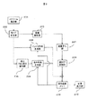
図1に実施例1に係る画像符号化装置のブロック図を示す。
First, a first embodiment will be described with reference to the drawings.
FIG. 1 is a block diagram of an image encoding apparatus according to the first embodiment.
画像符号化装置は、ブロック分割部101、予測誤差計算部102、イントラ予測部104、PMV予測符号化部107、適応PMV選択部106、動き探索部105、復号画像メモリ103、DCT変換部108、量子化部109、エントロピー符号化部110、逆量子化部111、逆DCT変換部112、モード選択部113、データ出力部114を備えている。
The image coding apparatus includes a
以下に画像符号化装置の各構成要素の動作を詳細に説明する。 The operation of each component of the image encoding device will be described in detail below.
なお、画像符号化装置の各構成要素の動作は、例えば、以下の記載の通り各構成要素の自律的な動作としても良い。また、コンピュータの制御部がコンピュータの記憶部が記憶するソフトウェアと協働することにより実現しても構わない。 The operation of each component of the image encoding device may be an autonomous operation of each component as described below, for example. Alternatively, the computer control unit may be realized in cooperation with software stored in the computer storage unit.
まずブロック分割部101は、符号化対象である原画像を入力し、これを符号化の単位であるブロックに分割する。ここで分割するブロックのサイズは、Coding Unit(CU)やPrediction Unit(PU)と呼ばれる16×16画素等の2のべき乗サイズ(画素数m×画素数nのブロック、m,n=2のべき乗、例. 128×128,64×64,32×32, 16×16, 16×8,8×16,8×8,4×4)のものを用いるが、サイズは可変であり異なるサイズのものが隣り合っていても構わない。以下では同じサイズのブロックが連続する場合を例に挙げ説明し、サイズが異なる場合のベクトルの選択方法については別途説明する。
First, the
予測誤差計算部102では、生成された予測画像と原画像との差分を取って残差成分を計算し出力する。予測方法については一般にイントラ(フレーム内)予測とインター(フレーム間)予測がある。イントラ予測は、イントラ予測部104で行われ、インター予測は、PMV予測符号化部107、適応PMV選択部106、動き探索部105とからなるインター予測部120で行われる。イントラ予測は符号化対象ブロックよりも前に符号化された同じフレームの情報を用い、インター予測は符号化対象フレームよりも前に符号化された、再生時間としては前または後ろのフレームの情報を用いる。これらは復号画像メモリ103に格納されている。
The prediction
ここで、イントラ予測部104や動き予測部、復号画像メモリ103は、説明のため一つだけ記載したが、符号化モード毎、フレーム毎にそれぞれ備えても良い。
Here, although only one
イントラ予測部104では、符号化対象ブロックよりも前に符号化された同じフレームの情報を用いて符号化対象ブロックの画素を予測する。イントラ予測の方法については既存の方式を用いればよい。
The
動き予測部120については、まず動き探索部105において復号画像メモリ103に格納されている参照フレームと符号化対象ブロックを用いて動きベクトル(Motion Vector: MV)の探索を行う。画素の精度は整数でも小数でもよく、フィルタによる参照フレームの補間により1/4画素精度が好適であるが、1/2、1/8でもかまわない。本実施例では動き探索方法については既存の方式を用いる。
For the
次に、適応PMV選択部106では、符号化対象ブロックの同じフレーム内の周囲ブロック、及び参照フレームの同じ位置とその周囲ブロックの情報を用いて、PMVを時間的、空間的な判別により適応的に選択する。本実施例では、PMVを、時間的な判別と空間的な判別とを双方備え適応的な判別を行うが、一方のみでもかまわない。方法、候補とする周囲ブロック、及びPMVの選択方法の詳細については後述する。 Next, the adaptive PMV selection unit 106 uses the surrounding block in the same frame of the encoding target block and the same position of the reference frame and the information of the surrounding block to adaptively determine the PMV by temporal and spatial discrimination. Select In this embodiment, the PMV is adaptively discriminated with both temporal discrimination and spatial discrimination, but only one of them may be used. Details of the method, the candidate surrounding blocks, and the PMV selection method will be described later.
図3を用いてPMVを選択する候補ブロックの例について説明する。既存の動きベクトル競合方式では、301のように符号化対象ブロックと同じ符号化対象フレームにある左側のブロック(A)、上側のブロック(B)と一番近い前方参照フレーム(L0[0])の符号化対象ブロックと同じ位置にあるブロック(Co-located Block)(S)を候補とし、A,B,Sのように順番に並べ、これらのうち同じベクトルがある場合には候補から除外して、最も符号化対象ブロックのベクトルに近いものを選択してフラグによって示す。なお、一番近い前方参照フレームを本実施例では採用したが、符号化済みのフレームであれば、後方参照フレームでもかまわない。また、一枚だけでなく、複数枚の符号化済みフレームを参照してもよい。 An example of a candidate block for selecting a PMV will be described with reference to FIG. In the existing motion vector competition method, as in 301, the left reference block (A) and the upper reference block (L0 [0]) closest to the upper block (B) in the same encoding target frame as the encoding target block. The block (Co-located Block) (S) at the same position as the current block to be encoded is taken as a candidate, arranged in order as A, B, S, and if there is the same vector among these, it is excluded from the candidate Thus, the one closest to the vector of the encoding target block is selected and indicated by a flag. Although the nearest forward reference frame is adopted in this embodiment, a backward reference frame may be used as long as it is an encoded frame. Further, not only one frame but also a plurality of encoded frames may be referred to.
一方、本実施例の適応PMV選択部で用いる適応動きベクトル選択方式では、302のように符号化対象ブロックの左側、上側だけでなく、右上(C)や左上(D)も候補に含める。また、参照フレームのブロックSの周囲ブロックも候補に含めることができる。つまり、適応PMV選択部が用いる候補ブロックの、(a)数、(b)空間的な位置(フレーム内のブロック)と(c)時間的な位置(別フレームのブロック)を変化させることができるようにする。
選択方法の詳細については後述する。
On the other hand, in the adaptive motion vector selection method used in the adaptive PMV selection unit of the present embodiment, not only the left side and the upper side of the encoding target block as in 302, but also the upper right (C) and upper left (D) are included in the candidates. In addition, blocks surrounding the block S of the reference frame can be included in the candidates. That is, (a) number, (b) spatial position (block in a frame) and (c) temporal position (block in another frame) of candidate blocks used by the adaptive PMV selection unit can be changed. Like that.
Details of the selection method will be described later.
また、本実施例の適応動きベクトル選択方式では、303のように候補ブロックのサイズが異なる場合で、最初に参照するべき位置のブロックが動きベクトルを持たない、または参照不可の場合、順次近傍のブロックが動きベクトルを持つかどうかをチェックし、利用可能な場合にはPMV選択の候補とする。具体的には、303においてB1が参照不可の場合、B2、B3、B4を順次チェックする。同様にA1が参照不可の場合、A2、A3、A4を、S1が参照不可の場合、S2、S3、S4をチェックする。符号化対象フレームの左上から近い順に走査すればよい。ブロックBの場合は、左から右、下から上の順、ブロックAの場合は上から下、右から左の順、ブロックSの場合は通常のラスタスキャン順、すなわち左から右、上から下の順となる。 Further, in the adaptive motion vector selection method of the present embodiment, when the size of the candidate block is different as in 303, if the block at the position to be referred to first does not have a motion vector or cannot be referenced, the neighboring blocks are sequentially It is checked whether the block has a motion vector, and if it is available, it is a candidate for PMV selection. Specifically, if B1 cannot be referenced in 303, B2, B3, and B4 are sequentially checked. Similarly, when A1 cannot be referred to, A2, A3 and A4 are checked. When S1 cannot be referred to, S2, S3 and S4 are checked. Scanning may be performed in order from the top left of the encoding target frame. For block B, left to right, bottom to top, for block A, top to bottom, right to left, for block S, normal raster scan order, left to right, top to bottom It becomes the order of.
次に、PMV予測符号化部107では、MVからPMVを引いて差分ベクトル(Differential Motion Vector: DMV)を計算し、これを符号化する。またMVを用いて参照フレームから動き予測を行い、予測ブロックを作成する。
Next, the PMV
DCT変換部108では、予測誤差計算部102から入力された残差成分に対してDCT変換が行われ、係数に変換される。続いて量子化部109に送られ、各変換係数が量子化される。量子化された係数はエントロピー符号化部110に送られ、一定の順序に従って可変長符号等を用いた情報圧縮が行われ、データがモード選択部113に送られる。一方で量子化された係数は逆量子化部111にも送られ、逆量子化によって変換係数に戻され、さらに逆DCT変換部112によって残差成分へと復元される。残差成分は、イントラ予測部104及び一連の動き予測部からの情報が加えられて、復号画像に戻り、復号画像メモリ103に記憶される。当該復号画像はモード選択部113に入力されてモード選択のために利用される。
In the
次に、モード選択部113では、複数の符号化モードに関する情報を基に、そのブロックについて最も符号化効率の高いモードを選択する。各符号化モードについて、原画像と復号画像との誤差(符号化誤差)とその符号化モードを利用した場合に発生する符号量を算出し、両者の関係から適切な符号化モードを選択する。例えば最も符号化効率の良い符号化モードを選択する方式としてRate-Distortion最適化方式などの既存の方式を用いればよい。この方式は、各マクロブロックについて全てのモードについて符号量と復号後の原画との符号化誤差を計算し、コスト計算式に従って最も良いモードを選択する方式となっている。
Next, the
最後に、データ出力部114が選択された符号を出力して符号化ストリームが作成され、画像の符号化が行われる。
Finally, the
次に、図5を用いて、画像符号化装置で用いられる画像符号化フローについて説明する。 Next, an image coding flow used in the image coding apparatus will be described with reference to FIG.
まず、ステップ501は、復号画像メモリ103から符号化対象となる原画像を入力し、ブロックに分割する処理である。ここで各ブロックのサイズは可変である。前述のCU、PUを用いればよい。ステップ501はブロック分割部101において実行される。
First,
次に、ステップ502では、ステップ501で取得した原画像のブロックについてイントラ予測を行う。イントラ予測については既存の方式を用いればよく、各イントラ予測モードに従って複数のモードについて予測を行う。このステップ502の処理はイントラ予測部104において実行される。
Next, in
次に、ステップ503では、イントラ予測された符号化ブロックの画素について残差成分を取得し、残差成分のDCT変換処理と量子化処理、エントロピー符号化処理とを行い、符号化データを算出する。また、さらに、当該符号化データからエントロピー復号処理、逆量子化、逆DCT変換処理を行い、復号画像の作成を行う。これにより符号化データと復号画像を出力する。このステップ503の処理は、予測誤差計算部102、DCT変換部108、量子化部109、エントロピー符号化部110において、この順に書く処理が実行される。
Next, in
ステップ504では、シーン解析を行う。図4を用いてシーン解析の概要について説明する。動画像シーケンスでは1つのGOP(Group of Picture: 時間方向の予測に関するフレームのまとまり)の内部においても、画像の特徴に変化がある場合がある。例えば、映画やドラマにおけるシーンチェンジ、テレビ中継におけるカメラの切替え等が発生する場合がある。図4では、P2のフレームとB3のフレームの間にシーン1とシーン2の切替えが発生した場合を示している。ここで既存の動きベクトル競合方式では、P4やB3のフレームはP2フレームの動きベクトルを参照するが、シーンが異なっているために効果的な動きベクトルを取得することができない。そこで、本実施例では複数の復号画像を解析してフラグを用いずにシーンチェンジを見つけるか、エンコーダ側でのシーン解析の結果、検出されたシーンチェンジ位置をフラグによってデコーダに伝えることによって、符号化対象フレームと参照フレームが異なるシーンに属する場合には、そのブロックをPMVの候補ブロックとはしないという処理を行うことができる。このようなシーン解析の処理はフレーム単位で行ってもよいし、ブロック単位で行ってもよい。この処理は、明確なブロックとしては図示しないが、インター予測部120内で動き探索部105による動き探索を行う前に実行する。
In step 504, scene analysis is performed. The outline of the scene analysis will be described with reference to FIG. In a moving image sequence, there may be a change in image characteristics even within one GOP (Group of Pictures). For example, there may be a scene change in a movie or drama, a camera change in a television broadcast, or the like. FIG. 4 shows a case where switching between
次に、ステップ505において、各インター予測モードに対して動き探索を行う。インター予測モードには、ブロックサイズの異なる動き予測モードや、Skipモード、Directモードなどが含まれる。動き探索の方法は既存の方式を用いればよい。このステップ505はインター予測部120内の動き探索部105において実行される。
Next, in
次にステップ506では、フレーム単位でPMV選択を行うか否かの判定を行う。PMV選択を行わない場合にはステップ510に進み、それ以外はステップ507に進む。続いてステップ507ではブロック単位でPMV選択を行うか否かの判定を行う。PMV選択を行わない場合にはステップ510に進み、それ以外はステップ508に進む。さらにステップ508ではPMV候補ブロックの調整を行い、条件によってどのブロックを候補ブロックに含め、どのブロックを含めないかを判定する。これらの処理はフレーム単位、及びブロック単位で切り換えることができ、こうした切り換えをフラグによって復号装置側へ伝送してもよいし、復号装置に同じ切り替え条件を保持させてもよい。
Next, in
フレーム単位でのPMV選択判定の詳細を、図8を用いて説明する。ステップ801はシーンチェンジか否かの判定を行うことによりPMV選択を行うか否かを判定する。これは前述のようにデコーダ側にてシーン解析処理を行ってフラグの伝送なしにPMV選択の処理を行うか否かの判定を行ってもよいし、エンコーダ側での判断をフラグによってデコーダ側に伝え判定してもよい。PMV選択を行わない場合には、median演算によってPMVを求める方式や、予め左側あるいは上側のブロックのベクトルをPMVとする方式など特定の方式を決めておく。 Details of PMV selection determination in frame units will be described with reference to FIG. Step 801 determines whether or not to perform PMV selection by determining whether or not a scene change has occurred. As described above, the scene analysis process may be performed on the decoder side as described above to determine whether to perform the PMV selection process without transmitting the flag, or the determination on the encoder side may be determined on the decoder side by the flag. You may judge it. When PMV selection is not performed, a specific method, such as a method for obtaining PMV by median calculation or a method in which the left or upper block vector is set to PMV, is determined in advance.
また、別の例として、ステップ802ではピクチャタイプの判定を行うことによりPMV選択を行うか否かを判定する。これは例えば符号化対象フレームがPピクチャであればPMV選択による動きベクトル予測を行い、そうでなければmedian演算等、他の手段を用いる。PピクチャではなくBピクチャとしてもよい。どのピクチャの時にどのように判断するかを判別するフラグを設けてもよい。
As another example, in
ブロック単位でのPMV選択判定の詳細を、図9を用いて説明する。ステップ901は符号化対象ブロックの符号化モードの種類を判別することによってPMV選択を行うか否かを判定する。例えば、特定のブロックサイズの時だけPMV選択を行う、あるいはSkipモードやDirectモードにはPMV選択を適用しないなどとすればよい。 Details of PMV selection determination in block units will be described with reference to FIG. Step 901 determines whether or not to perform PMV selection by determining the type of encoding mode of the encoding target block. For example, PMV selection may be performed only for a specific block size, or PMV selection may not be applied to Skip mode or Direct mode.
また、別の例として、ステップ902では候補ブロックの符号化モードの種類を判別することによってPMV選択を行うか否かを判定する。例えば、候補ブロックがすべてイントラ符号化モードであればPMV選択を行わない。
As another example, in
上記のような方式により、フレーム単位またはブロック単位でPMV選択を行うか否かを切り換えることができる。 With the above method, it is possible to switch whether or not PMV selection is performed in units of frames or blocks.
ブロック単位でのPMV選択を行う候補ブロックの調整方法の詳細を、図10を用いて説明する。ここではPMV選択を行う場合に、候補ブロックの符号化モードやベクトルを持つか否か、参照可能か否かによって候補ブロックから除外したり、他の候補ブロックを追加したりといった処理を行う。 Details of a method for adjusting candidate blocks for performing PMV selection in units of blocks will be described with reference to FIG. In this case, when PMV selection is performed, processing such as exclusion from candidate blocks or addition of other candidate blocks is performed depending on whether or not the encoding mode and vector of the candidate block are present and whether or not reference is possible.
まず、ステップ1001では、符号化対象フレームの候補ブロック、例えば図3のA、Bから、まだチェックしていないブロックを一つ選択する。これをブロックXとする。
First, in
次に、ステップ1002では、ブロックXが参照可能かどうか調べる。もし参照不可であればステップ1003に進み、参照可能であればステップ1004に進む。参照不可とはブロック位置が画面の範囲外にある等のためにブロックの情報が取得できない状態であり、参照可能とはブロックの情報が取得できることであり、ブロックの情報にはベクトル、参照フレーム番号が含まれる。
Next, in
ステップ1003ではブロックXを0ベクトルに設定するか、候補ブロックから除外する。どちらにするかは予め定める。例えばステップ1003では0ベクトルに設定する。
「0ベクトル」とは各成分の値が0のベクトルである。
In
A “0 vector” is a vector in which the value of each component is 0.
ステップ1004ではブロックXがベクトルを持つか否かを調べる。イントラ符号化されたブロックであればベクトルは持たない。ベクトルを持たない場合はステップ1005に進み、ベクトルを持てばステップ1006に進む。
In
ステップ1005ではブロックXを0ベクトルに設定するか、候補ブロックから除外する。どちらにするかは予め定める。例えばステップ1005では候補ブロックから除外する。
In
ステップ1006ではブロックXと符号化対象ブロックの参照フレーム番号が一致するかどうか調べる。例えば符号化対象ブロックが一方向予測で、ブロックXが双方向予測である場合、L0またはL1のどちらかが一致すればよい。また、符号化対象ブロックが双方向予測で、ブロックXが一方向予測である場合は不一致となる。不一致であればステップ1007に進み、一致すればステップ1008に進む。
In
ステップ1007ではブロックXを0ベクトルに設定するか、候補ブロックから除外する。どちらにするかは予め定める。例えばステップ1007では候補ブロックから除外する。
In
ステップ1008では符号化対象フレーム内に他にチェックする候補ブロックがあるかどうか判定し、他にチェックするブロックがある場合にはステップ1001に戻る。そうでなければステップ1009に進む。
In
ステップ1009では、参照フレームの候補ブロック、例えば図3のSから、まだチェックしていないブロックを一つ選択する。これをブロックYとする。
In
ステップ1010ではブロックYがベクトルを持つか否かを調べる。イントラ符号化されたブロックであればベクトルは持たない。ベクトルを持たない場合はステップ1011に進み、ベクトルを持てばステップ1012に進む。
In
ステップ1011ではブロックYを0ベクトルに設定するか、候補ブロックから除外する。どちらにするかは予め定める。例えばステップ1011では候補ブロックから除外する。
In
ステップ1012ではブロックYと符号化対象ブロックの参照フレーム番号が一致するかどうか調べる。例えば符号化対象ブロックが一方向予測で、ブロックYが双方向予測である場合、L0またはL1のどちらかが一致すればよい。また、符号化対象ブロックが双方向予測で、ブロックYが一方向予測である場合は不一致となる。不一致であればステップ1013に進み、一致すればステップ1014に進む。
In
ステップ1013ではブロックYを0ベクトルに設定するか、候補ブロックから除外する。どちらにするかは予め定める。例えばステップ1013では候補ブロックから除外する。
In
ステップ1014では符号化対象ブロック、またはブロックYが双方向予測モードかどうかを調べる。どちらかが双方向予測モードであればステップ1015に進み、そうでなければステップ1016に進む。
In
ステップ1015ではブロックYを0ベクトルに設定するか、候補ブロックから除外する。どちらにするかは予め定める。例えばステップ1015では候補ブロックから除外する。
In
ステップ1016では参照フレーム内に他にチェックする候補ブロックがあるかどうか判定し、他にチェックするブロックがある場合にはステップ1009に戻る。
In
ここでは各条件に対応してステップ1003、1005、1007、1011、1013、1015において、ブロックXまたはブロックYを0ベクトルに設定するか、候補ブロックから除外する処理を行った。これに対し、例えば候補ブロックとして図3のCやDの位置のブロックを候補ブロックに追加してもよい。例えば、S、A、Bのうち、候補ブロックが0の場合はCとDを候補ブロックに追加し、1つの場合はCを候補ブロックに追加する。予めCやD、さらに他のブロックを候補ブロックに加えておき、その中からベクトルを選んでもよい。
Here, in
例えば、L0[0]のピクチャがイントラ符号化されている場合には、候補ブロックからSを除外し、その代わりにCを加えればよい。あるいは、ブロックAが参照不可の場合にはブロックCを用いればよい。 For example, when the picture of L0 [0] is intra-coded, S may be excluded from the candidate blocks and C may be added instead. Alternatively, block C may be used when block A cannot be referenced.
上記のようなPMV選択を行うか否か、あるいは候補ブロック調整の方法については、フレーム単位あるいはブロック単位でフラグによって予め決められた方式を切り換えてもよい。すなわち、以下のような方法がありうる。
・どれかの方式に方式を統一する
・フレーム単位で切り替え可能としフラグでどの方式を選んだかを示す
・ブロック単位で切り替え可能としフラグでどの方式を選んだかを示す
図10に示した条件には以下のようなものがあり、これらは判定の順序を変えてもよい。
・候補ブロックが参照不可かどうか
・候補ブロックが動きベクトルを持つか否か
・候補ブロックと符号化対象ブロックの符号化タイプが異なるかどうか(例えば、候補ブロックが双方向予測(B予測)で符号化対象ブロックが一方向予測(P予測))
・候補ブロックと符号化対象ブロックの参照フレーム番号が一致するかどうか
・候補ブロック、符号化対象ブロックが双方向予測かどうか
候補ブロックの調整を行う方式としては、以下のようなものがある。
・候補ブロックを候補ブロックから除外する
・候補ブロックのベクトルを0ベクトルとして処理する
・符号化対象フレーム内の別のブロックを候補ブロックに加える
・参照フレーム内の別のブロックを候補ブロックに加える
・図3の303に示す別のブロックを候補ブロックに加える
・符号化タイプが一致する場合だけ処理し、それ以外は候補ブロックから除外する
・参照フレーム番号が合う場合だけ処理し、それ以外は候補ブロックから除外する
・参照フレーム番号が合うベクトルを他のベクトルに当てはめて両方処理する
続いて、ステップ509ではPMVを選択して差分ベクトルを計算し符号化する。PMVは候補ブロックのベクトルの中から最も符号化対象ブロックのベクトルに近いベクトルを選択する。ベクトルの各成分を符号化した時に最も符号量が小さくなるベクトルを選択する。選択されたベクトルはフラグとして伝送される。これは候補ブロックを順に並べ、1ビットであれば0の時は先頭の候補ブロックのベクトル、1の時は次の候補ブロックのベクトルが選ばれたことになる。候補ブロックの順番は、例えばA、B、Sのブロックが合った時、まずA、B、Sの順に並べ、同じベクトルがあった場合には除外し、先頭から2つのブロックが並べられ比較されることになる。
As to whether or not to perform PMV selection as described above, or as a candidate block adjustment method, a method predetermined by a flag may be switched for each frame or block. That is, there can be the following methods.
・ Unify the method to any method ・ Indicates which method can be switched by frame and selected by flag ・ Indicates which method can be switched by block and selected by flag The conditions shown in FIG. There are the following, which may change the order of determination.
・ Whether the candidate block cannot be referenced ・ Whether the candidate block has a motion vector ・ Whether the candidate block and the encoding target block are different in encoding type (for example, the candidate block is encoded by bidirectional prediction (B prediction)) Target block is one-way prediction (P prediction))
-Whether the reference frame number of the candidate block and the encoding target block match-Whether the candidate block and the encoding target block are bidirectional prediction The methods for adjusting the candidate block include the following.
・ Exclude candidate block from candidate block ・ Process vector of candidate block as 0 vector ・ Add another block in encoding target frame to candidate block ・ Add another block in reference frame to candidate block 3. Add another block shown at 303 in the process to the candidate block. Process only when the encoding type matches, exclude it from the candidate block. Process only when the reference frame number matches, otherwise process from the candidate block. Exclude / Apply the vector that matches the reference frame number to the other vector and perform both processing. Subsequently, in
選択されるベクトルが2ビットで示される場合を以下に示す。候補ブロックは図302に示すA、B、S、Cの4つであったとする。上記の例と同様に符号化対象ブロックのベクトルに最も近いベクトルを選択し、A:00、B:01、C:10、S:11のような形で符号を伝送する。例えば、これらのうち候補ブロックから除外されるものがあれば、そのブロックの順序を繰り上げる。選択したベクトルを示すビット数はフレーム単位、ブロック単位で切り替えてもよい。その場合には別途切り換えを示すフラグを伝送する。 The case where the selected vector is indicated by 2 bits is shown below. Assume that there are four candidate blocks A, B, S, and C shown in FIG. Similar to the above example, a vector closest to the vector of the encoding target block is selected, and the code is transmitted in the form of A: 0, B: 01, C: 10, S: 11. For example, if any of these is excluded from the candidate blocks, the order of the blocks is increased. The number of bits indicating the selected vector may be switched in units of frames or blocks. In that case, a flag indicating switching is transmitted separately.
図11に選択されるベクトルの符号の記述方法の例を示す。現在の1つ前の符号化対象ブロックの候補ブロック番号をPとし、候補ブロックの数をNとする。現在の符号化対象ブロックの候補ブロック番号をXとする。もし現在の符号化対象ブロックの候補ブロック番号がPであれば0を符号Cとする。そうでなければ、まず1を出力し、さらに続けて(X - P - 1) % N を出力する。逆に、符号Cが0の時は現在の符号化対象ブロックの候補ブロック番号Xは、1つ前の候補ブロック番号Pと同じである。そうではなく符号Cの先頭ビットが1であるときは、先頭ビットを除いた残りの符号をC^として、X = (P + C^ + 1 ) % Nとなる。このようにすることにより、連続して同じ候補ブロック番号が選ばれる場合に符号量を短くすることができる。
FIG. 11 shows an example of a method for describing the code of the vector selected. Let P be the candidate block number of the current previous encoding target block, and N be the number of candidate blocks. Let X be the candidate block number of the current encoding target block. If the current encoding candidate block number is P, 0 is set as the code C. Otherwise,
なお、これらのステップ506からすステップ509の処理は適応PMV選択部106で実行される。
Note that the processing from
次に、ステップ510ではPMV計算とベクトル符号化が行われる。ここではPMVの選択は行われず、通常のmedian演算によってPMVの計算が行われる。これは左側A、上側B、右上Cまたは左上Dのベクトルの各成分についてmedian演算を行い、PMV決定するものである。PMVが決定された後、符号化対象ブロックのベクトルとの差分ベクトルを計算し符号化する。
このステップ510の処理は、PMV予測符号化107で実行される。
Next, in
The processing in
ステップ511では、各インター予測モードについて動き予測を行い、符号化ブロックの画素について残差成分を取得し、残差成分のDCT変換処理と量子化処理、エントロピー符号化処理とを行い、符号化データを算出する。フテップ511に含まれるここまでの各処理は、DCT変換部108、量子化部109、エントロピー符号化部110で実行される。またさらに、当該符号化データからエントロピー復号処理、逆量子化、逆DCT変換処理を行い、復号画像の作成を行う。これにより符号化データと復号画像を出力する。ステップ511に含まれるこれまで各処理は、逆量子化部111、逆DCT変換部112で行われる。
In
次に、ステップ512では、ステップ503およびステップ511の処理結果に従い、各符号化モードについての画像符号化結果を比較して、当該ブロックについて出力する符号化モードを決定する。ステップ512の処理は、モード選択部113で実行される。
Next, in
次に、ステップ513では、ステップ512で選択した符号化モードにおける符号化データを符号化ストリームとして出力する。ステップ513の処理は、データ出力部114で実行される。
Next, in
以上説明したように、実施例1における符号化処理が行われる。 As described above, the encoding process according to the first embodiment is performed.
以上説明した実施例1に係る画像符号化装置及び画像符号化方法によれば、既存の符号化方式よりも精度が高く、かつ符号量の少ないインター予測が可能となり、既存方式よりも圧縮効率の高い画像符号化装置及び画像符号化方法を実現することが可能となる。 According to the image coding apparatus and the image coding method according to the first embodiment described above, inter prediction with higher accuracy and less code amount than the existing coding method is possible, and the compression efficiency is higher than that of the existing method. A high image encoding device and image encoding method can be realized.
また、実施例1に係る画像符号化装置及び画像符号化方法は、これらを用いた記録装置、携帯電話、デジタルカメラ等に適用することが可能である。 In addition, the image coding apparatus and the image coding method according to the first embodiment can be applied to a recording apparatus, a mobile phone, a digital camera, and the like using these.
以上説明した実施例1に係る画像符号化装置及び画像符号化方法によれば、符号化データの符号量を低減し、当該符号化データを復号した場合の復号画像の画質の劣化を防ぐことが可能となる。すなわち、高い圧縮率とより良い画質とを実現することができる。 According to the image encoding device and the image encoding method according to the first embodiment described above, it is possible to reduce the code amount of the encoded data and prevent deterioration of the image quality of the decoded image when the encoded data is decoded. It becomes possible. That is, a high compression rate and better image quality can be realized.
次に、図2に実施例2に係る画像復号装置のブロック図の例を示す。 Next, FIG. 2 shows an example of a block diagram of an image decoding apparatus according to the second embodiment.
本実施例の画像復号装置は、ストリーム解析部201、モード判定部202、係数解析部203、イントラ予測合成部204、適応PMV選択復号部205、動き予測合成部206、逆量子化部207、逆DCT変換部208、復号画像メモリ209、画像出力部210を備えている。
The image decoding apparatus according to the present embodiment includes a
以下に、画像復号装置の各構成要素の動作を詳細に説明する。なお、画像復号装置の各構成要素の動作は、例えば、以下の記載の通り各構成要素の自律的な動作としても良い。また、例えば、コンピュータの制御部や記憶部が記憶するソフトウェアと協働することにより実現しても構わない。 The operation of each component of the image decoding device will be described in detail below. The operation of each component of the image decoding device may be an autonomous operation of each component as described below, for example. Further, for example, it may be realized by cooperating with software stored in a control unit or storage unit of a computer.
まず、ストリーム解析部201が、入力された符号化ストリームを解析する。ここで、ストリーム解析部201は、パケットからのデータ抽出処理や各種ヘッダ、フラグの情報取得処理も行う。さらに各ブロックの処理を行う。
First, the
また、このとき、ストリーム解析部201に入力される符号化ストリームは、実施例1に係る画像符号化装置及び画像符号化方法により生成された符号化ストリームである。その生成方法は、実施例1に示したとおりであるので説明を省略する。実施例3に示すデータ記録媒体から読み出した符号化ストリームであってもよい。その記録方法は後述する。
At this time, the encoded stream input to the
次に、モード判定部202は、各ブロックについて、フラグ等によって指定された符号化モードの判別を行う。以下の復号処理は、当該判別結果の符号化モードに対応する処理が行われる。以下にそれぞれの符号化モードについての処理を説明する。
Next, the
まず、符号化モードがイントラ符号化である場合には、イントラ予測合成部204がイントラ予測と予測画像の合成を行う。この方法は従来の方法を用いればよい。ここで、イントラ予測合成部204は合成した予測画像を出力する。
First, when the coding mode is intra coding, the intra
符号化モードがフレーム間のインター予測による符号化である場合には、動き予測と予測画像の合成が行われる。まず適応PMV選択復号部205により、適応的にPMVが選択され、復号された差分ベクトルと合成されて動きベクトルが復元される。PMVの選択方法についてはエンコーダとデコーダが同じPMVを選択するように動作するため、実施例1に記述した方法と同様である。
When the encoding mode is encoding by inter prediction between frames, motion prediction and prediction image synthesis are performed. First, the adaptive PMV
続いて、動き予測合成部206が、復元された動きベクトルを用いてブロック内の画素について参照フレームを利用して動き予測を行う。ここで、動き予測合成部206は合成した予測画像を出力する。
Subsequently, the motion
一方、係数解析部203は、入力符号化ストリームに含まれる各マクロブロックの符号化データを解析し、残差成分の符号化データを出力する。この時、モード判定部202の判別結果の符号化モードに対応する処理が行われる。
On the other hand, the
逆量子化部207は符号化データに逆量子化処理を行い、これを逆DCT変換部208に送る。逆DCT変換部208は、逆量子化された係数を逆DCT変換し残差成分を復元する。
The
上記のようにして復元された各符号化モードの残差成分は、イントラ予測合成部204や動き予測合成部206から出力される予測画像と加算されて、復号画像に戻り、復号画像メモリ209に格納される。復号画像メモリ209には、現在復号しているフレームの情報と、過去に復号したフレームの情報が格納されており、イントラ予測合成部204や動き予測合成部206に参照される。
The residual component of each coding mode restored as described above is added to the prediction image output from the intra
最後に復号された画像が画像出力部210によって出力され、画像の復号が行われる。
The last decoded image is output by the
次に、図6を用いて、実施例2に係る画像復号装置における画像復号方法の流れについて説明する。 Next, the flow of the image decoding method in the image decoding apparatus according to the second embodiment will be described with reference to FIG.
まず、ステップ601で、復号対象となる符号化ストリームを取得する。次に、ステップ602では、ステップ601において取得した符号化ストリームに含まれる符号化モードフラグと符号化データを解析する。このステップ601、ステップ602はストリーム解析部201で実行される。
First, in step 601, an encoded stream to be decoded is acquired. Next, in
次に、ステップ603では、ステップ602において解析した符号化モードフラグを用いて、当該符号化データに含まれる一の符号化単位(ブロック単位や画素単位など)についての符号化モードを判定する。ここでイントラ符号化モードである場合にはステップ604に進み、インター符号化モードである場合にはステップ605に進む。このステップ603は、モード判定部202で実行される。
Next, in
ステップ604では、符号化モードによって指定された方法に従ってイントラ予測を行う。これは既存のイントラ予測方法を用いればよい。このステップ604は、イントラ予測合成部204で実行される。
In
ステップ605では、フレーム単位の諸条件、フラグの情報に従って、該フレームに対してPMV選択を行うかどうかを判定する。フレーム単位でPMV選択を行うか否かの判定はエンコーダとデコーダが同じ処理をするように動作するため、実施例1に記述した方法と同様である。PMV選択を行わない場合にはステップ609に進み、それ以外はステップ606に進む。ステップ606では符号化モード、ブロック単位の諸条件、フラグの情報に従って、該ブロックに対してPMV選択を行うかどうかを判定する。ブロック単位でPMV選択を行うか否かの判定はエンコーダとデコーダが同じ処理をするように動作するため、実施例1に記述した方法と同様である。PMV選択を行わない場合にはステップ609に進み、それ以外はステップ607に進む。
In
ステップ607ではPMV候補ブロックの調整を行う。ここでは条件によってどのブロックを候補ブロックに含め、どのブロックを含めないかを判定する。PMV候補ブロックの調整はエンコーダとデコーダが同じ処理をするように動作するため、実施例1に記述した方法と同様である。
In
ステップ608ではPMV選択とベクトル復号が行われる。PMVの選択方法は、エンコーダとデコーダが同じ処理をするように動作するため、実施例1に記述した方法と同様である。ベクトルの復号は、PMVと復号された差分ベクトルを合成して符号化対象ブロックの動きベクトルを復元する。 In step 608, PMV selection and vector decoding are performed. The PMV selection method is the same as the method described in the first embodiment because the encoder and the decoder operate so as to perform the same processing. In the vector decoding, the PMV and the decoded difference vector are combined to restore the motion vector of the encoding target block.
次に、ステップ609ではPMV計算とベクトル復号が行われる。PMVの計算方法は、エンコーダとデコーダが同じ処理をするように動作するため、実施例1に記述した方法と同様である。ベクトルの復号は、PMVと復号された差分ベクトルを合成して符号化対象ブロックの動きベクトルを復元する。これらのステップ605、ステップ606、ステップ607、ステップ608及びステップ609は、適応PMV選択復号部205で実行される。
Next, in
ステップ610では復元されたベクトルと参照フレームを用いてインター予測を行い、予測画像を合成する。これは判定された符号化モードに応じて、図2における画像復号装置のイントラ予測合成部204、動き予測合成部206が、それぞれの対応する符号化モードの場合に予測画像の合成処理を行えばよい。このステップ610は、動き予測合成部206で実行される。
In
ステップ611では、予測画像と残差成分を合成し、復号画像の生成を行う。まず符号化データを解析し、当該符号化データについて逆量子化処理、逆DCT変換処理を行い、前記一の符号化単位についての残差成分の復号を行う。これに予測画像を合成して復号画像の生成を行い、メモリに記憶する。最後に、ステップ612では、生成された復号画像の出力を行う。このステップ611の各処理は、係数解析部203、逆量子化部207、逆DCT変換部208、復号画像メモリ209及び画像出力部210で実行される。
In
なお、本実施例においても、例に示す以外にも、符号化モードで用いるブロックのサイズなどをパラメータとして、各符号化モードを細分化して規定した符号化ストリームを、復号対象ストリームとしてもよい。 In this embodiment, besides the example, an encoded stream that is defined by subdividing each encoding mode using a block size used in the encoding mode as a parameter may be set as a decoding target stream.
以上説明した実施例2に係る画像復号装置及び画像復号方法によれば、既存の符号化方式よりも精度が高く、かつ符号量の少ないインター予測が可能となり、既存方式よりも圧縮効率の高い画像復号装置及び画像復号方法を実現することが可能となる。 According to the above-described image decoding apparatus and image decoding method according to the second embodiment, inter prediction with higher accuracy and less code amount than the existing encoding method is possible, and the image has higher compression efficiency than the existing method. A decoding device and an image decoding method can be realized.
また、実施例2に係る画像復号装置及び画像復号方法は、これらを用いた再生装置、携帯電話、デジタルカメラ等に適用することが可能である。 In addition, the image decoding apparatus and the image decoding method according to the second embodiment can be applied to a reproduction apparatus, a mobile phone, a digital camera, and the like using these.
以上説明した実施例2に係る画像復号装置及び画像復号方法によれば、符号量の少ない符号化データをより高画質に復号することが可能となる。 According to the image decoding apparatus and the image decoding method according to the second embodiment described above, it is possible to decode encoded data with a small code amount with higher image quality.
次に、図7に実施例1に係る画像符号化装置または画像符号化方法により生成された符号化ストリームが格納されたデータ記録媒体を示す。 Next, FIG. 7 shows a data recording medium in which an encoded stream generated by the image encoding device or the image encoding method according to the first embodiment is stored.
本実施例に係る符号化ストリームは、実施例1に係る画像符号化装置または画像符号化方法により生成された符号化ストリームである。その生成方法は、実施例1に示したとおりであるので、説明を省略する。 The encoded stream according to the present embodiment is an encoded stream generated by the image encoding device or the image encoding method according to the first embodiment. Since the generation method is as shown in the first embodiment, the description is omitted.
ここで、本実施例に係る符号化ストリームは、データ記録媒体701上にデータ列702として記録される。データ列702は、所定の文法に従う符号化ストリームとして記録されている。以下ではH.264/AVC規格の一部を変更したものとして説明する。 Here, the encoded stream according to the present embodiment is recorded as a data string 702 on the data recording medium 701. The data string 702 is recorded as an encoded stream according to a predetermined grammar. The following description assumes that a part of the H.264 / AVC standard has been changed.
まず、H.264/AVCでは、シーケンスパラメータセット703、ピクチャパラメータセット704、スライス705、706、707からストリームが構成される。以下、1つのスライスに1つの画像(ピクチャ)が格納される場合を示す。 First, in H.264 / AVC, a stream is composed of a sequence parameter set 703, a picture parameter set 704, and slices 705, 706, and 707. Hereinafter, a case where one image (picture) is stored in one slice will be described.
各スライスの内部には、それぞれのブロックに関する情報708が含まれている。ブロックに関する情報708の内部には、ブロックごとにそれぞれの符号化モードを記録する領域があり、これを符号化モードフラグ709とする。
Each slice includes
以上説明した実施例3に係るデータ記録媒体によれば、既存方式よりも圧縮効率が高い符号化ストリームで記録されているので、多くの画像を記録することができる。 Since the data recording medium according to the third embodiment described above is recorded with the encoded stream having higher compression efficiency than the existing method, many images can be recorded.
なお、以上説明した各図、各方法等の実施例のいずれを組み合わせてもよい。 It should be noted that any of the embodiments described above, such as each figure and each method, may be combined.
101…ブロック分割部、102…予測誤差計算部、103…復号画像メモリ、104…イントラ予測部、105…動き探索部、106…適応PMV選択部、107…PMV予測符号化部、108…DCT変換部、109…量子化部、110…エントロピー符号化部、111…逆量子化部、112…逆DCT変換部、113…モード選択部、114…データ出力部、120…インター予測部
201…ストリーム解析部、202…モード判定部、203…係数解析部、204…イントラ予測合成部、205…適応PMV選択復号部、206…動き予測合成部、207…逆量子化部、208…逆DCT変換部、209…復号画像メモリ、210…画像出力部
DESCRIPTION OF
Claims (1)
前記画像を構成する復号対象ブロックにおいて、
前記符号化ストリームから得られる符号化モードの情報に従って、前記復号対象ブロックの周囲のブロックを含む複数の候補ブロックの動きベクトルから動きベクトルを選択し、前記動きベクトルを用いて、前記復号対象ブロックの動きベクトルを復号する第1ステップと、
前記復号対象ブロックの動きベクトルと参照画像とを用いて予測画像を生成する第2ステップとを備え、
前記第1ステップにおける動きベクトルの選択処理は、前記復号対象ブロックと同じフレームにあり前記復号対象ブロックと隣接する第1のブロックと、前記復号対象ブロックとは別のフレームの前記復号対象ブロックと同じ位置にある第2のブロックとから、候補ブロックの選択を行う処理であり、
該動きベクトルの選択処理では、
前記第1のブロックのうち、前記対象ブロックの左側に位置するブロックと前記対象ブロックの上側に位置するブロックとの動きベクトルを比較し、同じ動きベクトルを有する場合には、前記対象ブロックの上側に位置するブロックを候補ブロックから除外し、
前記第1のブロックに参照不可のブロックが含まれる場合には、前記参照不可のブロックを動きベクトルの候補ブロックから除外し、他のブロックを候補ブロックに追加する処理を行い、
前記候補ブロックに追加するブロックの数は、既に候補ブロックとして選択されているブロックの数に応じて変更することを特徴とする画像復号化方法。 An image decoding method for decoding a coded stream obtained by coding an image,
In the decoding target block constituting the image,
According to the encoding mode information obtained from the encoded stream, a motion vector is selected from the motion vectors of a plurality of candidate blocks including blocks around the decoding target block, and the motion vector is used to select the decoding target block. A first step of decoding a motion vector;
A second step of generating a predicted image using a motion vector of the decoding target block and a reference image,
The motion vector selection process in the first step is the same as the first block adjacent to the decoding target block in the same frame as the decoding target block, and the decoding target block in a frame different from the decoding target block. A process of selecting candidate blocks from a second block at a position,
In the selection process of the motion vector,
Among the first blocks, the motion vectors of the block located on the left side of the target block and the block located on the upper side of the target block are compared. It excludes the block position from the candidate block,
If the first block includes a non-referenceable block, the non-referenceable block is excluded from the motion vector candidate blocks, and another block is added to the candidate block .
The number of blocks to be added to the candidate block, the image decoding method and changes according to the number of blocks that have already been selected as the candidate block.
Priority Applications (1)
| Application Number | Priority Date | Filing Date | Title |
|---|---|---|---|
| JP2014210460A JP5750191B2 (en) | 2014-10-15 | 2014-10-15 | Image decoding method |
Applications Claiming Priority (1)
| Application Number | Priority Date | Filing Date | Title |
|---|---|---|---|
| JP2014210460A JP5750191B2 (en) | 2014-10-15 | 2014-10-15 | Image decoding method |
Related Parent Applications (1)
| Application Number | Title | Priority Date | Filing Date |
|---|---|---|---|
| JP2011007429A Division JP2012151576A (en) | 2011-01-18 | 2011-01-18 | Image coding method, image coding device, image decoding method and image decoding device |
Related Child Applications (1)
| Application Number | Title | Priority Date | Filing Date |
|---|---|---|---|
| JP2015024922A Division JP5911982B2 (en) | 2015-02-12 | 2015-02-12 | Image decoding method |
Publications (3)
| Publication Number | Publication Date |
|---|---|
| JP2015035822A JP2015035822A (en) | 2015-02-19 |
| JP2015035822A5 JP2015035822A5 (en) | 2015-04-02 |
| JP5750191B2 true JP5750191B2 (en) | 2015-07-15 |
Family
ID=52544013
Family Applications (1)
| Application Number | Title | Priority Date | Filing Date |
|---|---|---|---|
| JP2014210460A Active JP5750191B2 (en) | 2014-10-15 | 2014-10-15 | Image decoding method |
Country Status (1)
| Country | Link |
|---|---|
| JP (1) | JP5750191B2 (en) |
Family Cites Families (7)
| Publication number | Priority date | Publication date | Assignee | Title |
|---|---|---|---|---|
| US7978769B2 (en) * | 2003-06-30 | 2011-07-12 | Ntt Docomo, Inc. | Method and apparatus for coding motion information |
| US7567617B2 (en) * | 2003-09-07 | 2009-07-28 | Microsoft Corporation | Predicting motion vectors for fields of forward-predicted interlaced video frames |
| JP5025286B2 (en) * | 2007-02-28 | 2012-09-12 | シャープ株式会社 | Encoding device and decoding device |
| JP5194833B2 (en) * | 2008-01-23 | 2013-05-08 | ソニー株式会社 | Encoding apparatus and method, recording medium, and program |
| WO2009115901A2 (en) * | 2008-03-19 | 2009-09-24 | Nokia Corporation | Combined motion vector and reference index prediction for video coding |
| JP5422168B2 (en) * | 2008-09-29 | 2014-02-19 | 株式会社日立製作所 | Video encoding method and video decoding method |
| WO2011131089A1 (en) * | 2010-04-22 | 2011-10-27 | Mediatek Inc. | Motion prediction method |
-
2014
- 2014-10-15 JP JP2014210460A patent/JP5750191B2/en active Active
Also Published As
| Publication number | Publication date |
|---|---|
| JP2015035822A (en) | 2015-02-19 |
Similar Documents
| Publication | Publication Date | Title |
|---|---|---|
| US11758179B2 (en) | Image encoding method, image encoding device, image decoding method, and image decoding device | |
| WO2010001917A1 (en) | Image processing device and method | |
| JP4527677B2 (en) | Moving picture coding method, moving picture coding apparatus, moving picture coding program | |
| KR102216320B1 (en) | Method for inter prediction and apparatus thereof | |
| WO2013009104A2 (en) | Inter prediction method and apparatus for same | |
| KR20140029383A (en) | Image coding device and image decoding device | |
| WO2010070818A1 (en) | Moving image encoding device, moving image encoding method, moving image decoding device and moving image decoding method | |
| CN113615173A (en) | Method and device for carrying out optical flow prediction correction on affine decoding block | |
| JP2006100871A (en) | Coder, coding method, program of coding method, and recording medium with the program recorded thereon | |
| JP6181242B2 (en) | Image decoding method | |
| JP5951915B2 (en) | Image decoding method | |
| JP5946980B1 (en) | Image decoding method | |
| JP5750191B2 (en) | Image decoding method | |
| JP5911982B2 (en) | Image decoding method | |
| WO2012090425A1 (en) | Moving image encoding device, moving image encoding method, and moving image encoding program, as well as moving image decoding device, moving image decoding method, and moving image decoding program | |
| US20240098300A1 (en) | Method and apparatus for implicitly indicating motion vector predictor precision | |
| US20240098299A1 (en) | Method and apparatus for motion vector prediction based on subblock motion vector | |
| JP2023549182A (en) | Method and apparatus for adaptive reordering of reference frames | |
| CN115668934A (en) | Image encoding/decoding method and apparatus having motion information determined based on inter-layer prediction and method of transmitting bitstream | |
| JP2012138838A (en) | Moving image decoding apparatus, moving image decoding method and moving image decoding program | |
| JP2012138837A (en) | Moving image encoding apparatus, moving image encoding method and moving image encoding program |
Legal Events
| Date | Code | Title | Description |
|---|---|---|---|
| A521 | Request for written amendment filed |
Free format text: JAPANESE INTERMEDIATE CODE: A523 Effective date: 20150212 |
|
| A871 | Explanation of circumstances concerning accelerated examination |
Free format text: JAPANESE INTERMEDIATE CODE: A871 Effective date: 20150212 |
|
| A975 | Report on accelerated examination |
Free format text: JAPANESE INTERMEDIATE CODE: A971005 Effective date: 20150225 |
|
| A131 | Notification of reasons for refusal |
Free format text: JAPANESE INTERMEDIATE CODE: A131 Effective date: 20150303 |
|
| A521 | Request for written amendment filed |
Free format text: JAPANESE INTERMEDIATE CODE: A523 Effective date: 20150410 |
|
| TRDD | Decision of grant or rejection written | ||
| A01 | Written decision to grant a patent or to grant a registration (utility model) |
Free format text: JAPANESE INTERMEDIATE CODE: A01 Effective date: 20150512 |
|
| A61 | First payment of annual fees (during grant procedure) |
Free format text: JAPANESE INTERMEDIATE CODE: A61 Effective date: 20150515 |
|
| R150 | Certificate of patent or registration of utility model |
Ref document number: 5750191 Country of ref document: JP Free format text: JAPANESE INTERMEDIATE CODE: R150 |
|
| S111 | Request for change of ownership or part of ownership |
Free format text: JAPANESE INTERMEDIATE CODE: R313111 |
|
| R350 | Written notification of registration of transfer |
Free format text: JAPANESE INTERMEDIATE CODE: R350 |
|
| R250 | Receipt of annual fees |
Free format text: JAPANESE INTERMEDIATE CODE: R250 |
|
| R250 | Receipt of annual fees |
Free format text: JAPANESE INTERMEDIATE CODE: R250 |
|
| R250 | Receipt of annual fees |
Free format text: JAPANESE INTERMEDIATE CODE: R250 |
|
| R250 | Receipt of annual fees |
Free format text: JAPANESE INTERMEDIATE CODE: R250 |
|
| S111 | Request for change of ownership or part of ownership |
Free format text: JAPANESE INTERMEDIATE CODE: R313111 |
|
| R350 | Written notification of registration of transfer |
Free format text: JAPANESE INTERMEDIATE CODE: R350 |
|
| R250 | Receipt of annual fees |
Free format text: JAPANESE INTERMEDIATE CODE: R250 |
|
| R250 | Receipt of annual fees |
Free format text: JAPANESE INTERMEDIATE CODE: R250 |