JP4865706B2 - Photonic band gap (PBF) material antenna having sidewalls surrounding the axis - Google Patents
Photonic band gap (PBF) material antenna having sidewalls surrounding the axis Download PDFInfo
- Publication number
- JP4865706B2 JP4865706B2 JP2007517328A JP2007517328A JP4865706B2 JP 4865706 B2 JP4865706 B2 JP 4865706B2 JP 2007517328 A JP2007517328 A JP 2007517328A JP 2007517328 A JP2007517328 A JP 2007517328A JP 4865706 B2 JP4865706 B2 JP 4865706B2
- Authority
- JP
- Japan
- Prior art keywords
- antenna
- probe
- central
- cavity
- central axis
- Prior art date
- Legal status (The legal status is an assumption and is not a legal conclusion. Google has not performed a legal analysis and makes no representation as to the accuracy of the status listed.)
- Expired - Fee Related
Links
- 239000000463 material Substances 0.000 title claims description 76
- 239000000523 sample Substances 0.000 claims description 93
- 239000004020 conductor Substances 0.000 claims description 43
- 230000005672 electromagnetic field Effects 0.000 claims description 8
- 230000010287 polarization Effects 0.000 claims description 8
- 239000003989 dielectric material Substances 0.000 claims description 7
- 230000001747 exhibiting effect Effects 0.000 claims description 5
- 230000005670 electromagnetic radiation Effects 0.000 claims description 4
- 240000001549 Ipomoea eriocarpa Species 0.000 claims description 2
- 235000005146 Ipomoea eriocarpa Nutrition 0.000 claims description 2
- 125000006850 spacer group Chemical group 0.000 description 8
- 230000005684 electric field Effects 0.000 description 7
- 230000005855 radiation Effects 0.000 description 7
- 239000000758 substrate Substances 0.000 description 4
- 239000006260 foam Substances 0.000 description 3
- 238000004519 manufacturing process Methods 0.000 description 2
- 239000002184 metal Substances 0.000 description 2
- 230000005540 biological transmission Effects 0.000 description 1
- 230000007423 decrease Effects 0.000 description 1
- 230000007547 defect Effects 0.000 description 1
- 239000000428 dust Substances 0.000 description 1
- 230000005284 excitation Effects 0.000 description 1
- 230000002452 interceptive effect Effects 0.000 description 1
- 238000000034 method Methods 0.000 description 1
- 230000000737 periodic effect Effects 0.000 description 1
- 238000004088 simulation Methods 0.000 description 1
Images


Classifications
-
- H—ELECTRICITY
- H01—ELECTRIC ELEMENTS
- H01Q—ANTENNAS, i.e. RADIO AERIALS
- H01Q15/00—Devices for reflection, refraction, diffraction or polarisation of waves radiated from an antenna, e.g. quasi-optical devices
- H01Q15/0006—Devices acting selectively as reflecting surface, as diffracting or as refracting device, e.g. frequency filtering or angular spatial filtering devices
- H01Q15/006—Selective devices having photonic band gap materials or materials of which the material properties are frequency dependent, e.g. perforated substrates, high-impedance surfaces
-
- H—ELECTRICITY
- H01—ELECTRIC ELEMENTS
- H01Q—ANTENNAS, i.e. RADIO AERIALS
- H01Q1/00—Details of, or arrangements associated with, antennas
- H01Q1/12—Supports; Mounting means
- H01Q1/22—Supports; Mounting means by structural association with other equipment or articles
- H01Q1/24—Supports; Mounting means by structural association with other equipment or articles with receiving set
- H01Q1/241—Supports; Mounting means by structural association with other equipment or articles with receiving set used in mobile communications, e.g. GSM
- H01Q1/242—Supports; Mounting means by structural association with other equipment or articles with receiving set used in mobile communications, e.g. GSM specially adapted for hand-held use
- H01Q1/245—Supports; Mounting means by structural association with other equipment or articles with receiving set used in mobile communications, e.g. GSM specially adapted for hand-held use with means for shaping the antenna pattern, e.g. in order to protect user against rf exposure
-
- H—ELECTRICITY
- H01—ELECTRIC ELEMENTS
- H01Q—ANTENNAS, i.e. RADIO AERIALS
- H01Q1/00—Details of, or arrangements associated with, antennas
- H01Q1/48—Earthing means; Earth screens; Counterpoises
-
- H—ELECTRICITY
- H01—ELECTRIC ELEMENTS
- H01Q—ANTENNAS, i.e. RADIO AERIALS
- H01Q1/00—Details of, or arrangements associated with, antennas
- H01Q1/52—Means for reducing coupling between antennas; Means for reducing coupling between an antenna and another structure
-
- H—ELECTRICITY
- H01—ELECTRIC ELEMENTS
- H01Q—ANTENNAS, i.e. RADIO AERIALS
- H01Q19/00—Combinations of primary active antenna elements and units with secondary devices, e.g. with quasi-optical devices, for giving the antenna a desired directional characteristic
- H01Q19/06—Combinations of primary active antenna elements and units with secondary devices, e.g. with quasi-optical devices, for giving the antenna a desired directional characteristic using refracting or diffracting devices, e.g. lens
-
- H—ELECTRICITY
- H04—ELECTRIC COMMUNICATION TECHNIQUE
- H04B—TRANSMISSION
- H04B1/00—Details of transmission systems, not covered by a single one of groups H04B3/00 - H04B13/00; Details of transmission systems not characterised by the medium used for transmission
- H04B1/38—Transceivers, i.e. devices in which transmitter and receiver form a structural unit and in which at least one part is used for functions of transmitting and receiving
- H04B1/3827—Portable transceivers
- H04B1/3833—Hand-held transceivers
- H04B1/3838—Arrangements for reducing RF exposure to the user, e.g. by changing the shape of the transceiver while in use
-
- H—ELECTRICITY
- H04—ELECTRIC COMMUNICATION TECHNIQUE
- H04M—TELEPHONIC COMMUNICATION
- H04M1/00—Substation equipment, e.g. for use by subscribers
- H04M1/02—Constructional features of telephone sets
- H04M1/0202—Portable telephone sets, e.g. cordless phones, mobile phones or bar type handsets
-
- H—ELECTRICITY
- H04—ELECTRIC COMMUNICATION TECHNIQUE
- H04M—TELEPHONIC COMMUNICATION
- H04M1/00—Substation equipment, e.g. for use by subscribers
- H04M1/02—Constructional features of telephone sets
- H04M1/0202—Portable telephone sets, e.g. cordless phones, mobile phones or bar type handsets
- H04M1/0206—Portable telephones comprising a plurality of mechanically joined movable body parts, e.g. hinged housings
- H04M1/0208—Portable telephones comprising a plurality of mechanically joined movable body parts, e.g. hinged housings characterized by the relative motions of the body parts
- H04M1/0214—Foldable telephones, i.e. with body parts pivoting to an open position around an axis parallel to the plane they define in closed position
-
- H—ELECTRICITY
- H05—ELECTRIC TECHNIQUES NOT OTHERWISE PROVIDED FOR
- H05K—PRINTED CIRCUITS; CASINGS OR CONSTRUCTIONAL DETAILS OF ELECTRIC APPARATUS; MANUFACTURE OF ASSEMBLAGES OF ELECTRICAL COMPONENTS
- H05K1/00—Printed circuits
- H05K1/02—Details
- H05K1/0213—Electrical arrangements not otherwise provided for
-
- H—ELECTRICITY
- H05—ELECTRIC TECHNIQUES NOT OTHERWISE PROVIDED FOR
- H05K—PRINTED CIRCUITS; CASINGS OR CONSTRUCTIONAL DETAILS OF ELECTRIC APPARATUS; MANUFACTURE OF ASSEMBLAGES OF ELECTRICAL COMPONENTS
- H05K1/00—Printed circuits
- H05K1/02—Details
- H05K1/14—Structural association of two or more printed circuits
- H05K1/148—Arrangements of two or more hingeably connected rigid printed circuit boards, i.e. connected by flexible means
Landscapes
- Engineering & Computer Science (AREA)
- Computer Networks & Wireless Communication (AREA)
- Signal Processing (AREA)
- Physics & Mathematics (AREA)
- Optics & Photonics (AREA)
- Variable-Direction Aerials And Aerial Arrays (AREA)
- Details Of Aerials (AREA)
- Aerials With Secondary Devices (AREA)
- Control Of Motors That Do Not Use Commutators (AREA)
- Waveguide Aerials (AREA)
Description
本発明は、軸を取り囲む側壁を有するフォトニックバンドギャップ(Photonic Band Gap:PBG)材料のアンテナに関するものである。 The present invention relates to an antenna of a photonic band gap (PBG) material having a sidewall surrounding an axis.
既知のPBG材料アンテナは、中心軸を完全に取り囲むと共に、この中心軸と離隔することによってPBG材料の広い周波数ストップバンド内に少なくとも1つの狭い周波数通過帯域を生成するのに好適な共振中央空洞を残しているPBG材料の側壁と;この空洞内に配置されており、狭い周波数通過帯域内に位置した所定の動作周波数において電磁放射を放射又は受信するべく電磁界を励起するのに好適な少なくとも1つの放射要素と;を有している。 Known PBG material antennas completely surround the central axis and are spaced apart from the central axis to create a resonant central cavity suitable for creating at least one narrow frequency passband within the wide frequency stopband of the PBG material. At least one suitable for exciting the electromagnetic field to radiate or receive electromagnetic radiation at a predetermined operating frequency located within the narrow frequency passband; and a sidewall of the remaining PBG material; And two radiating elements.
例えば、仏国特許出願第99/14521号(FR99/14521)は、プローブを取り囲む同軸シリンダによって形成された側壁を有するPBG材料アンテナの製造を提案している。この特許出願に記述されている好適な実施例は、プレート又はパッチプローブを使用している。しかしながら、このようなパッチプローブを具備したアンテナの利得は、あまり高いものではない。 For example, French Patent Application No. 99/14521 (FR99 / 14521) proposes the manufacture of a PBG material antenna having sidewalls formed by coaxial cylinders surrounding the probe. The preferred embodiment described in this patent application uses a plate or patch probe. However, the gain of an antenna equipped with such a patch probe is not very high.
本発明は、このようなアンテナの利得の改善を追求するものである。 The present invention seeks to improve the gain of such an antenna.
従って、本発明は、このようなPBG材料から製造されたアンテナを提供し、この場合に、・1つの又はそれぞれの放射要素が、中心軸に平行な電磁界を励起するべく空洞内に配置されており、・少なくとも1つの放射要素は、中央空洞のその他のモードよりも強力に半径方向共振(radial resonance)を示す中央空洞モードを励起するのに好適である。 The present invention thus provides an antenna manufactured from such a PBG material, where one or each radiating element is arranged in the cavity to excite an electromagnetic field parallel to the central axis. At least one radiating element is suitable for exciting a central cavity mode exhibiting a radial resonance stronger than the other modes of the central cavity.
前述の方式によって1つの又はそれぞれのプローブを配置及び選択することにより、このようなPBG材料アンテナの利得を増大可能であることが判明している。尚、本明細書においては、「半径方向共振(radial resonance)」という用語は、中心軸に対して垂直のプレーン内において確立される共振を意味している。又、半径方向共振を示すこれらの空洞モードは、磁界Hzによって励起される場合には、「TEモード」という用語により、そして、電界Ezによって励起される場合には、「TMモード」という用語によっても知られている。 It has been found that the gain of such PBG material antennas can be increased by placing and selecting one or each probe in the manner described above. In this specification, the term “radial resonance” means resonance established in a plane perpendicular to the central axis. These cavity modes exhibiting radial resonances are also referred to by the term “TE mode” when excited by the magnetic field H z and “TM mode” when excited by the electric field E z . Also known by terminology.
PBG材料アンテナの実施例は、・1つの又はそれぞれの放射要素が、半径方向共振を示す中央空洞モードのみを励起するのに好適であり、・放射要素の少なくとも1つが、中心軸に平行又はこれと一致した個別の電気的ダイポールを形成しており、・放射要素の少なくとも1つが、中心軸に平行又はこれと一致した個別の磁気的ダイポールを形成しており、・アンテナが、空洞内に配置された少なくとも1つのプローブを含んでおり、この1つの又はそれぞれのプローブが、放射要素の1つ又は複数のものを具備しており、・少なくとも1つの導電体プレーンが中心軸に対して垂直であり、1つの又はそれぞれのプローブが導電体プレーンの1つによって支持されており、・プローブの1つが、導電体プレーンを中心として対称的に他方の電気的なイメージとなるように、少なくとも2つのプローブが互いに対して配置されており、・導電性材料の中心コアが中心軸上にアライメントされており、1つの又はそれぞれのプローブが中心コアによって支持されており、・導電体が、1つの又はそれぞれのプローブに電力を供給すると共に、中心コアの内部を貫通しており、・複数の放射要素が、中心コアの周囲の周りに均一に分布しており、・支持部が、1つの又はそれぞれのプローブを空洞内において定位置に保持しており、この支持部は、空洞を充填している材料の比誘電率と±3内において等しい比誘電率の材料から製造されており、・1つの又はそれぞれのプローブは、電気的ダイポールとワイヤ/プレートプローブを有する組から選択されており、・複数の放射要素が中心軸に沿って異なる高さに配設されており、・複数の放射要素が、中心軸に沿って同一の高さに配設されており、・中央空洞が、その内部を中心軸が貫通している2つの開口端部を有し、アンテナは、これらの開口端部の1つを閉鎖する少なくとも1つの閉鎖キャップを含んでおり、閉鎖キャップは、1〜3の範囲内に位置する比誘電率の誘電材料から製造されており、・PBG材料の側壁は、金属性のPBG材料の構造を有しており、・放射要素は、同一の動作周波数において動作するべく適合されており、個別の電気的ダイポールを形成する1つの又はそれぞれの放射要素は、円偏波を生成するべく、個別の磁気的ダイポールを形成する1つの又はそれぞれの放射要素に対して直角位相において励起されており、・空洞が樽の形態を有しており、樽の対称軸が中心軸と一致しており、・空洞は、中心軸と一致した対称軸の円形シリンダであり、・中央空洞は、その内部を中心軸が貫通している2つの開口端部を有し、中心コアは、相対的に狭い部分によって1つに接続された2つの朝顔形に開いた部分を有しており、朝顔形に開いた部分のそれぞれは、開口端部のそれぞれのものを部分的に閉鎖している、という各特徴の中の1つ又は複数のものを包含可能である。 Embodiments of the PBG material antenna are suitable for exciting only a central cavity mode in which one or each radiating element exhibits radial resonance, and at least one of the radiating elements is parallel to the central axis or A separate electrical dipole that matches the central axis, and at least one of the radiating elements forms a separate magnetic dipole that is parallel to or coincides with the central axis, and the antenna is located in the cavity At least one probe, the one or each probe comprising one or more of the radiating elements, wherein at least one conductor plane is perpendicular to the central axis Yes, one or each probe is supported by one of the conductor planes, one of the probes being symmetrical about the other conductor plane At least two probes are arranged with respect to each other so that there is an aerial image, the central core of conductive material is aligned on the central axis, and one or each probe is supported by the central core The electrical conductors supply power to one or each probe and penetrate the interior of the central core, and the plurality of radiating elements are evenly distributed around the perimeter of the central core • the support holds one or each probe in place in the cavity, which is equal to the relative permittivity of the material filling the cavity within ± 3 The one or each probe is selected from a set comprising an electrical dipole and a wire / plate probe, and is centered on a plurality of radiating elements The radiating elements are arranged at the same height along the central axis, and the central cavity passes through the inside of the central axis. And the antenna includes at least one closing cap that closes one of these opening ends, the closing cap being in the range of 1 to 3 The sidewalls of the PBG material have a metallic PBG material structure, and the radiating elements are adapted to operate at the same operating frequency and are individually One or each radiating element forming an electrical dipole is excited in quadrature with respect to one or each radiating element forming a separate magnetic dipole to produce circular polarization; The cavity has the form of a barrel The symmetry axis of the barrel coincides with the central axis. The cavity is a circular cylinder with the symmetry axis coincident with the central axis. The central cavity has two openings through which the central axis passes. The central core has two morning glory-shaped open portions connected together by a relatively narrow portion, each of the morning glory-shaped open portions of the open end One or more of each feature may be included, each being partially closed.
添付の図面を参照して記述され、且つ、純粋に一例として付与されている以下の説明を参照することにより、本発明に関する理解を更に深めることができよう。 A further understanding of the present invention can be obtained by reference to the following description, which is described with reference to the accompanying drawings and given purely by way of example.
図1は、PBG材料から製造されたアンテナを示しており、これには、全体として参照符号2が付与されている。アンテナ2は、中心軸6を完全に取り囲むと共に、この中心軸から離隔することによって共振中央空洞8を残している垂直側壁4を含んでいる。
FIG. 1 shows an antenna manufactured from PBG material, which is generally given the
壁4は、軸6を中心とした対称性を有する円形シリンダである。壁4は、半径方向の周期性を有する1次元のPBG材料から製造されている。例えば、PBG材料は、内部シリンダ10、中間シリンダ12、及び外部シリンダ14を順番に有している。内部シリンダ10は、比誘電率εr1と一定の直径d1を具備する誘電性の材料から製造されている。シリンダ10の内部直径は、空洞8の外部直径に対応している。一例として、εr1は、以下の説明においては、9に等しい。
The wall 4 is a circular cylinder having symmetry about the
シリンダ12は、比誘電率εr2を具備した材料から製造されており、一定の厚さd2を有している。比誘電率εr2は、εr1とは異なっている。一例として、このケースにおいては、この材料は、空気であり、εr2は、1に等しい。
The
シリンダ14は、シリンダ10の比誘電率に等しい比誘電率を具備した材料から製造されており、これは、一定の厚さd1を有している。
The
空洞8は、PBG材料の半径方向の周期性欠陥に対応するべく、シリンダ12と同一の材料によって充填されている。
The
空洞8の直径dcは、この空洞が、壁4を形成しているPBG材料の広い周波数ストップバンド内に少なくとも1つの狭い周波数通過帯域を生成するのに好適な共振空洞となるように、選択されている。このために、空洞8の直径dcは、次の関係を使用することにより、アンテナ2に望ましい動作周波数の関数として選択されている。
The diameter d c of the
dc=α・λg2=α/(fT・√εr2) (1) d c = α · λ g2 = α / (f T · √ε r2 ) (1)
ここで、・λg2は、空洞8を充填している材料内の動作周波数の波長であり、・αは、0.75〜0.85の範囲内に位置するべく選択された一定の係数であり、これは、好ましくは、0.8に等しく、・
Where λ g2 is the wavelength of the operating frequency in the material filling the
は、光の速度であり、・fTは、アンテナ2の望ましい動作周波数である。
Is the speed of light, and f T is the desired operating frequency of the
係数αの値は、PBG材料の広い周波数ストップバンド内に狭い周波数通過帯域を生成するべく、実験的に決定される。 The value of the coefficient α is determined experimentally to produce a narrow frequency passband within the wide frequency stopband of the PBG material.
厚さd1及びd2も、次の関係を使用することにより、望ましい動作周波数の関数として選択される。 The thicknesses d 1 and d 2 are also selected as a function of the desired operating frequency by using the following relationship:
d1=λg1/4=c/(4・fT√εr1) (2)
d2=λg2/4=c/(4・fT√εr2) (3)
d 1 = λ g1 / 4 = c / (4 · f T √ε r1 ) (2)
d 2 = λ g2 / 4 = c / (4 · f T √ε r2 ) (3)
ここで、λg1及びλg2は、それぞれ、シリンダ10及び12の材料内における動作周波数に対応した波長である。
Here, λ g1 and λ g2 are wavelengths corresponding to operating frequencies in the materials of the
このようなPBG材料から製造されたアンテナの伝達係数は、仏国特許出願第99/14521(FR99/14521)の図7に示されているものに類似している。 The transmission coefficient of an antenna made from such PBG material is similar to that shown in FIG. 7 of French Patent Application No. 99/14521 (FR99 / 14521).
一例として、以下の説明においては、望ましい動作周波数fTは、5.5ギガヘルツ(GHz)に等しく、dcは、43ミリメートル(mm)に等しく、d1は、10.5mmに等しく、d2は、3.5mmに等しい。 As an example, in the following description, the desired operating frequency f T is equal to 5.5 gigahertz (GHz), d c is equal to 43 millimeters (mm), d 1 is equal to 10.5 mm, d 2 Is equal to 3.5 mm.
軸6に平行な方向における壁4の高さHは、第1として、利得と、第2として、アンテナ2の通過帯域幅の間における良好な折衷値に対応するように選択されている。一般には、高さが大きくなるほど、利得は大きくなるが、アンテナ2の通過帯域幅が狭くなる。この例においては、アンテナ2の高さは、214mmに等しくなるように選択されている。
The height H of the wall 4 in the direction parallel to the
この実施例においては、アンテナ2は、軸6に対して垂直に延長すると共に半分の高さにおいてアンテ2と交差している導電体プレーン20を具備している。この例においては、導電体プレーンは、その幅と比較して厚さが小さい円筒形のプレートである。このプレートは、軸6に中心を有しており、その直径は、シリンダ14の外部直径を上回っている。例えば、プレーン20の直径は、95mmである。
In this embodiment, the
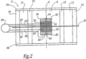
図2においては、図1を参照して前述したアンテナ2の要素に対して同一の参照符号が付与されている。
2, the same reference numerals are given to the elements of the
空洞8の内部には、2つの同一のワイヤ/プレートプローブ24、26が配置されている。これらのプローブ24、26は、仏国特許出願第93/10597号(FR93/10597)の開示内容に従って製造されている。尚、この時点においては、それぞれのワイヤ/プレートプローブが、2つの平行導電体プレート30、32と、これらの導電体プレートに対して垂直に延長し、且つ、両方の導電体プレートに対して電気的に接続されている放射要素34と、を有していることのみを思い出して頂きたい。
Inside the
それぞれのプレート30、32は、円形であり、13mmの直径を有している。プレート30及び32の間に延長している放射要素34の長さは、望ましい動作周波数fTの関数である。このケースにおいては、長さは、0.8mmに等しくなるように選択されている。
Each
プレート30及び32は、電圧又は電流ジェネレータ/レシーバなどの電気的なジェネレータ/レシーバ38に接続されている。このために、導電体40、42が、プローブ24のプレート30及び32をジェネレータ/レシーバ38の個々の入力にそれぞれ接続している。同様に、導電体44、46は、プローブ26のプレート30及び32をジェネレータ/レシーバ38の個々の入力にそれぞれ接続している。
これらの導電体40、42、44、及び46は、プローブ24及び26によって放射される電界を妨げることを回避するべく、プレーン20の表面に固定されているか、或いは、プレーン20の厚さ内に内蔵されている。
These
ワイヤ/プレートプローブの放射要素は、その放射要素の軸と一致した軸の個別の電気的ダイポールと等価である。このような状況下において、この例においては、プローブ24及び26は、放射要素34の軸が軸6とアライメントするように空洞8内に配置されている。従って、プローブ24、26のそれぞれは、軸6と一致した軸の個別の電気的ダイポールを形成している。このような条件下において、それぞれのプローブ24及び26は、軸6に平行な電界Ezのみを励起している。このような特性の利点については、アンテナの動作について説明する際に後述する。
The radiating element of a wire / plate probe is equivalent to an individual electrical dipole with an axis that coincides with the axis of the radiating element. Under such circumstances, in this example, the
プローブ24及び26は、これらのプローブのそれぞれが、プレーン20を中心として対称的に他方のものの電気的イメージとなるように、プレーン20の両側に配設されている。従って、プレーン20は、アンテナ2の放射パターン内になんらの非対称性をも導入していない。
The
プローブ24及び26は、プレーン20により、空洞8内において定位置に保持されている。更に詳しくは、この例においては、それぞれのプローブ24、26は、個別のスペーサ50、52によってプレーン20に対して固定されている。空洞8内の電界分布を妨げることを回避するべく、これらのスペーサ50及び52は、空洞8を充填している材料の比誘電率に±3内において等しい比誘電率を具備した材料から製造されている。この例においては、スペーサに使用されている材料は、1に等しい比誘電率を具備したRhoacellフォームである。
The
一例として、これらのスペーサは、プレーン20の表面から5mmだけ離れたところにプローブ24、26のそれぞれをオフセットするべく、5mmの厚さを具備している。これらのスペーサは、アンテナ利得を増大させるべく機能する。
As an example, these spacers have a thickness of 5 mm to offset each of the
空洞8内又はシリンダ12内に埃が侵入することを防止するべく、アンテナ2は、空洞8の2つの開口端部のそれぞれに円形の閉鎖キャップ54、56を含んでいる。それぞれのキャップ24又は56の直径は、空洞8の開口端部とシリンダ12の端部の両方を閉鎖するのに十分な大きさに選択されている。従って、キャップ54及び56は、例えば、シリンダ14の外部直径と同一の直径を具備可能である。空洞8内の電磁界分布を妨げることを回避するべく、これらのキャップは、1〜3の範囲内に位置した比誘電率を具備する誘電材料から製造されている。
In order to prevent dust from entering the
アンテナ2が動作している際には、プローブ24及び26は、電界Ezのみを励起する。この結果、空洞のTMモードのみが励起されることになり、その他の空洞モードは、励起されず、これは、その相対的に良好な性能を意味している。
When the
一例として、前述のアンテナ2の特定の構成においては、・アンテナの最大固有利得が約9.4デシベル(dB)であり、・−3dBの放射通過帯域が5.4GHz〜5.8GHzの範囲内に位置しており、・アンテナの利得と帯域幅の積が62に等しいという模擬性能が得られている。
As an example, in the specific configuration of the
利得と帯域幅の積は、アンテナの線形最大固有利得(即ち、デシベルで表現されていないもの)にパーセンテージとして表現された通過帯域を乗算することによって得られる。通過帯域は、通過帯域の幅をその中心周波数によって除算し、この結果に100を乗算することにより、パーセンテージとして表現されている。 The product of gain and bandwidth is obtained by multiplying the linear maximum intrinsic gain of the antenna (ie, not expressed in decibels) by the passband expressed as a percentage. The passband is expressed as a percentage by dividing the width of the passband by its center frequency and multiplying this result by 100.
アンテナ2の放射パターンは、プレーン20を中心として対称性を有すると共に、軸6を中心とした円対称性をも有している。これは、主に、空洞8内のプローブ24及び26の配置に起因している。
The radiation pattern of the
アンテナ2の固有の利得値は、類似してはいるがプレーン20に平行に配設されたパッチプローブを具備し(即ち、実際には、ワイヤ/プレートプローブである)、且つ、その放射要素の軸が軸6にアライメントされていないアンテナによって得られるであろうものよりも優れている。この得られる利得の改善は、特定タイプのプローブの選択と、空洞8内におけるそれらのプローブの特定の位置により、説明可能である。アンテナ2内には、以下において、それぞれ、導波動作モードと放射動作モードと呼んでいる2つの別個の動作モードが存在することが判明している。導波動作モードにおいては、エネルギーは、軸6に沿って導波され、壁4を通じて放射されることはない。導波動作モードは、アンテナ2が使用されている際には有用ではなく、従って、これは、消失エネルギーに対応している。対照的に、放射動作モードにおいては、エネルギーは、壁4を通じて放射され、軸6に沿って導波されることはない。放射動作モードは、空洞8が半径方向共振を示すモード(即ち、TE及びTMモード)に対応している。
The inherent gain value of the
従って、これらの半径方向共振を示す空洞モードを優先的に励起することにより、アンテナの性能、特にその利得が改善されることになる。 Therefore, preferential excitation of the cavity modes exhibiting these radial resonances improves the antenna performance, particularly its gain.
図3は、PBG材料から製造された別のアンテナ60を示している。この図3においては、図2を参照して前述した要素には同一の参照符号が付与されており、これらに関する説明は省略する。
FIG. 3 shows another
アンテナ2と比べた場合のアンテナ60の相違点は、基本的に、このアンテナが、1つのワイヤ/プレートプローブ62のみを具備しているという事実と、このプローブを空洞8内に固定している方法にある。プローブ24又は26と比べた場合のプローブ62の相違点は、その寸法のみである。この例においては、プレート30及び32は、9mmの直径を具備しており、放射要素34の長さは、5mmである。プローブ24及び26と同様に、プローブ62の放射要素34は、軸6にアライメントした状態にあり、これは、実質的に空洞8の高さの半分の位置に配置されている。それぞれのプレート30、32は、個別の導電体66、68を介してジェネレータ/レシーバ38に接続されている。但し、導電体40、42とは異なり、導電体66及び68は、軸6に沿って垂直に延長しており、このそれぞれは、空洞8内の電磁界を妨げることを回避するべく、例えば、個別の同軸ケーブルによって構成されている。
The difference of the
この例においては、プローブ62は、誘電材料の支持部70に対して配置又は固定されている。この例においては、支持部70は、空洞8の中央において定位置にプローブ62を保持するように、例えば、キャップ56に固定されている。スペーサ50及び52について説明したものと同様に、支持部70は、空洞8を充填している誘電材料の比誘電率に±3内において等しい比誘電率を具備した誘電材料から製造されている。一例として、支持部70の材料は、Rhoacellフォームである。
In this example, the
導電体66及び68は、支持部70を貫通している。
The
アンテナ2の場合には、プローブ62は、空洞8のTMモードのみを励起している。従って、アンテナ60の性能における改善も、アンテナ2のものと同様に説明可能である。
In the case of the
図4は、中心軸84を完全に取り囲むと共に、この中心軸から共振空洞86によって離隔している側壁82を有するアンテナ80を示している。アンテナ80は、軸84に沿って延長する導電性材料の円筒形の中心コア88を具備している。
FIG. 4 shows an
壁82は、一次元のPBG材料から製造されており、これは、アンテナ2の壁4と同様に、3つの垂直シリンダ90、92、及び94を並置することによって形成されている。シリンダ90は、空洞86の外部直径dcを定義している内部直径の内部シリンダである。アンテナが中心コアを具備している場合には、関係(1)は、次の関係によって置換されることになる。
The
dc=λg2=dac=c(fT・√εr2)+dac (4) d c = λ g2 = d ac = c (f T · √ε r2 ) + d ac (4)
ここで、dacは、中心コア88の直径である。
Here, d ac is the diameter of the
シリンダ90、92、及び94の厚さは、前述の関係(2)及び(3)を使用して算出される。
The thicknesses of the
アンテナ2と同様に、このように構築された空洞86は、PBG材料の広い周波数ストップバンド内に狭い周波数通過帯域を生成する。
Similar to
壁82の高さは、第1として、利得と、第2として、通過帯域幅の間の折衷値の関数として選択される。
The height of the
この例においては、コア88は、4mmの外部直径を具備した導電性材料の中空シリンダである。
In this example, the
図5Aを参照して後程詳述するように、コア88は、空洞86内において定位置にワイヤ/プレートプローブ98を保持するべく機能している。コア88は、プローブ98に電力を供給する2つの導電体100及び102のシールドとしても使用されている。
The core 88 functions to hold the wire /
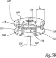
図5Bは、プローブ98を更に詳しく示している。このプローブは、プレート104及び106に垂直に延長している4つの放射要素108〜111によって電気的に相互接続された2つの平行円形導電性プレート104及び106を有している。一例として、放射要素は、断面が正方形である。この例においては、これらの断面は、1平方ミリメートル(mm2)である。放射要素のそれぞれの高さは、5mmである。
FIG. 5B shows the
プレート104及び106のそれぞれは、コア88を収容するのに好適な中央開口部114又は116を具備している。放射要素108〜111は、これらの開口部114及び116の周りに均等に分布している。この例においては、中央開口部114又は116とプレート104又は106の外周部の間の幅Liは、5.5mmである。それぞれの中央開口部の直径は、9mmである。
Each of the
プローブ98は、プレート104及び106の間において放射要素108〜111に対して平行に延長する導電体ロッド118をも有している。このロッド118は、その端部の1つによってプレート104に固定されており、もう1つの端部は、自由な状態にある。従って、このロッドは、プレート106からは電気的に絶縁された状態において、プレート104に対して電気的に接続されている。ロッド118の自由端は、導電体100に接続されている。導電体102は、プレート106に電気的に接続されている。
The
プローブ98は、壁82の高さの中間の位置において、コア88により、空洞86内の定位置に保持されている。更に詳しくは、コア88は、開口部114及び116を貫通しており、プローブ98は、誘電材料のリング120によってコア88に固定されている。リング120を構成している材料の比誘電率は、空洞86を充填している材料の比誘電率に等しい(又は、これに近接している)。例えば、この例においては、材料は、Rhoacell(登録商標)フォームであってよい。
The
プローブ98に接続された導電体100及び102の端部は、空洞86内の電磁界を妨げることを回避するべく、軸84に対して垂直のプレーン内においてリング120を貫通して延長している。導電体100及び102の中間部分は、コア88の内部に収容されており、これらの端部をジェネレータ/レシーバ38と同一の電気エネルギージェネレータ/レシーバ122に対して接続している。
The ends of the
導電体101及び102は、導電性材料によって空洞86から分離されているため、これらの電磁放射は、プローブ98からの電磁放射とは干渉しない。
Since the
プローブ98の放射要素は、軸84の周りに均等に分布しているため、アンテナ80の放射パターンは、第1には、軸84に対して垂直であり且つ放射要素の中間部分を包含しているプレーンを中心とした対称性と、第2には、軸84を中心とした円対称性を有している。
Since the radiating elements of the
プローブ98は、4つの個別の電気的ダイポールと等価であり、これは、空洞8のTMモードのみを励起している。
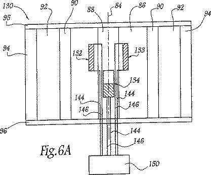
以上においては、ワイヤ/プレートプローブを具備しているという特定の状況において、アンテナ2、60、及び80について説明している。図6Aは、プローブ98が、4つの同一の電気的ダイポールによって置換されているという点を除いて、アンテナ80の構造に同一の構造のアンテナ130を示している。この図6Aにおいては、図5Aを参照して前述したアンテナ130の要素には同一の参照符号が付与されており、この場合にも、これらの説明は省略する。
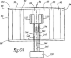
The above describes the
この例においては、図示を簡単にするべく、アンテナ130が有している4つのダイポールの中から、3つのプリントされたダイポール132〜134のみが示されている。図6B及び図6Cには、これらのダイポールの中の1つのものの背面及び前面が、それぞれ、更に詳しく示されている。
In this example, only three printed dipoles 132 to 134 are shown from among the four dipoles of the
それぞれのプリントされたダイポールは、矩形の誘電性基板138を有している。この例においては、基板の計測値は、幅が8.1mmであり、長さが42mmである。背面は、背面の上部全体を占めている導電性材料のストリップ140を具備している。この例においては、ストリップ140は、基板の上端から22mmの長さを具備している。逆に、前面上においては、導電性材料のストリップ142が、前面の下部全体を占めている。又、このストリップ142の基板の下端からの長さの計測値は、22mmである。
Each printed dipole has a rectangular
これらのストリップ140及び142は、個々の導電体144及び146を介して電気的エネルギージェネレータ/レシーバ150に接続されている。
These
これらのダイポールは、コア88により、空洞86内において定位置に保持されている。更に詳しくは、それぞれのダイポールは、アンテナ利得を改善するべく、0.81mmの厚さを有するエアギャップにより、コア88の外部表面から離隔している。この例においては、導電体144及び146は、スペーサ又はその他の支持部に対するリソースを具備することなしに、プリントされたダイポールに接続されたそれらの端部が、コア88に対してダイポールを固定する要素として機能するべく十分に堅固なものになるように選択されている。
These dipoles are held in place in the
この例においては、プリントされたダイポールは、コア88に沿って異なる高さに配置されており、この結果、軸86に沿って生成される電界Ezを拡散させるべく機能している。これにより、アンテナの性能、特に、その利得が改善される。この例においては、ダイポール132及び133は、軸84に垂直であると共に中間の高さにおいてPBG材料の側壁と交差している中間プレーンのすぐ上に配設されている。プリントされたダイポール132及び133は、これらのダイポールの中のいずれかが、軸84を中心として対称的に他方のもののイメージを構築するように、互いに対して配設されている。同様に、ダイポール134と図6Aには示されていないもう1つのダイポールも、対称軸84を中心として互いにイメージとなるように、中間プレーンのすぐ下に配設されている。
In this example, the printed dipoles are located at different heights along the
プリントされたダイポールは、個別の電気的ダイポールと等価な放射要素を構成している。この例においては、これらのプリントされたダイポールは、対応する個別の電気的ダイポールの軸が軸86に対して平行になるように、垂直になっている。従って、これらのダイポールは、空洞のTMモードのみを励起する。プリントされたダイポールを使用することによって得られる性能の改善は、アンテナの中心軸に対して平行な放射要素を有するワイヤ/プレートプローブを使用した際に得られるものに類似している。
The printed dipole constitutes a radiating element equivalent to an individual electrical dipole. In this example, these printed dipoles are vertical so that the axis of the corresponding individual electrical dipole is parallel to
以上のアンテナは、いずれも、誘電性のPBG材料から製造された側壁を具備している。図7Aは、誘電性のPBG材料の側壁が金属性のPBG材料の側壁162によって置換されたアンテナ160を示している。又、アンテナ160においては、円筒形の中心コアが、相対的に狭い断面の中央部分170を介して互いに接続された2つの朝顔形に開いた端部166及び168を具備した中心コア164によって置換されている。
Each of the above antennas has a side wall made of a dielectric PBG material. FIG. 7A shows an
誘電性のPBG材料とは異なり、金属性のPBG材料は、少なくとも1つの方向において空間的な周期性を示す導電性材料の分布を具備している。この例においては、壁162は、水平の円174の周囲に沿って均一に分布した一連の垂直の金属バー172によって形成されている。これらの金属バー172は、異なる導電性を有する材料によって(例えば、空気によって)互いに分離されている。
Unlike dielectric PBG materials, metallic PBG materials have a distribution of conductive material that exhibits spatial periodicity in at least one direction. In this example, the
一例として、壁162の寸法は、関係(2)、(3)、及び(4)を使用して決定される。
As an example, the dimensions of the
壁162は、アンテナの中心軸と一致した円対称性の軸176を有している。壁162のPBG材料は、軸176の方向においては、なんらの周期性をも有していない。このような状況においては、壁162は、プローブの垂直偏波(即ち、軸176に平行な又はこれと一致する個別の電気的ダイポールに等価な1つ又は複数のプローブによって生成されるもの)のみを変更する。
この例においては、4つの垂直のプリントされたダイポールが、壁162の高さの半分の位置において、中心部分170の周りに固定されている。対称的な放射パターンを得るべく、これらのダイポールは、中心部分170の外周部に沿って均一に分布している。
In this example, four vertical printed dipoles are fixed around the
前述の実施例と同様に、コア164は、中空の導電性材料から製造されている。朝顔形に開いた端部166及び168は、共振空洞の開口端部を部分的に遮断している。このような中心コアの構成により、側壁及び中心コアが円筒形であるアンテナの利得と比較した場合に、約10%だけアンテナの利得が増大する。
Similar to the previous embodiment, the
金属性のPBG材料を使用して側壁を製造する方式は、いくつかの利点、特に、誘電性のPBG材料から製造された同一のアンテナと比較した場合に、アンテナ性能を改善するという利点を有している。又、金属性のPBG材料は、誘電性のPBG材料よりも廉価である。 Manufacturing a sidewall using a metallic PBG material has several advantages, particularly improved antenna performance when compared to the same antenna made from a dielectric PBG material. is doing. Also, metallic PBG materials are less expensive than dielectric PBG materials.
図8は、側壁が、アンテナの中心軸180に対して平行な方向に一次元の周期性を有する別の金属性のPBG材料を使用して製造されているアンテナ180を示している。更に詳しくは、側壁は、軸182上に中心を有する導電性材料のリング184の垂直のスタックから形成されている。これらのリングは、例えば、空気などの導電性が異なる材料内に形成された一定のピッチにおいて互いに離隔している。この例におけるように垂直方向において一次元の周期性を有する金属性のPBG材料は、水平偏波(即ち、軸182に対して平行な磁界Hzによって生成されるもの)のみを変更する。
FIG. 8 shows an
アンテナ180の共振空洞内には、磁界Hzを励起するのに好適なプローブ186が配置されている。磁界Hzのみを励起するべく、このプローブ186は、軸182と一致する又はこれに平行な軸の個別の磁気的ダイポールに等価な放射要素のみを有している。一例として、プローブ186は、アンテナ180の高さの中間の位置における軸182に垂直のプレーン内に配置された電流ループであり、このループの回転軸は、軸182と一致している。前述のプローブと同様に、このプローブ186は、アンテナ180が、基本的に、導波動作モードではなく、放射動作モードを示すように、半径方向共振を示す空洞モードのみを励起する。但し、個別の電気的ダイポールに等価なプローブとは異なり、プローブ186によって励起される空洞モードは、TEモードである。
A
空洞内において定位置にプローブ186を保持するべく、図1〜図7を参照して説明した共振空洞内においてプローブを定位置に保持するための様々な技法を使用可能である。この例においては、空洞内においてプローブ186を保持するための手段は、図8を簡単にするべく、図示されてはいない。
Various techniques for holding the probe in place within the resonant cavity described with reference to FIGS. 1-7 can be used to hold the
図9は、アンテナ2及び180の特性を組み合わせたアンテナ200を示している。更に詳しくは、アンテナ200の側壁は、金属性のPBG材料202と誘電性のPBG材料204を並置することによって構成されている。一例として、金属性のPBG材料202は、アンテナ180のものと同一であり、誘電性のPBG材料204は、アンテナ2のものと同一である。
FIG. 9 shows an
共振空洞内には、2つの放射要素206及び208を有するプローブが配置されている。放射要素206は、アンテナ200の中心軸210と一致した軸の個別の電気的ダイポールと等価である。放射要素208は、こちらもアンテナの中心軸と一致した軸の個別の磁気的ダイポールと等価である。このような条件下において、放射要素206は、電界Ezのみを励起し、放射要素208は、磁界Hzのみを励起する。又、金属性のPBG材料202の存在は、中心軸210に平行な方向においてのみ一次元の周期性を示しているため、放射要素206によって生成される垂直偏波を変更しないことを認識されたい。
A probe having two radiating
従って、アンテナ200は、垂直偏波及び水平偏波の両方を有している。更には、この例においては、円偏波を生成するべく、放射要素206は、放射要素208に対して直交位相において励起されている。
Therefore, the
これらの放射要素206及び208は、前述の実施例の中のいずれかの開示内容に基づいて、共振空洞内において定位置に保持されている。図9の図示を簡単にするべく、これらを定位置に保持するための手段は図示されていない。
These radiating
図10は、アンテナ222の側壁220の垂直断面及び透視図である。この側壁は、樽の形状を有している。一例として、壁220は、誘電性のPBG材料を使用して製造されている。このような側壁の形状によれば、樽の形状を有する中央空洞が生成され、且つ、一定した断面を有するシリンダから形成された側壁を具備するアンテナと比較した場合に、約10%だけアンテナの利得が増大する。
FIG. 10 is a vertical sectional view and a perspective view of the
前述の開示内容を使用することにより、前述のプローブの1つ又は複数のものが樽の形状の中央空洞内において定位置に保持されている。尚、これらのプローブ及びこれらの構造は、図示を簡単にするべく、図10には示されていない。 By using the foregoing disclosure, one or more of the aforementioned probes are held in place within a barrel-shaped central cavity. Note that these probes and their structure are not shown in FIG. 10 for ease of illustration.
PBG材料アンテナの多数のその他の実施例が存在している。前述の実施例において、例えば、ワイヤ/プレートプローブ、電気的ダイポール、又は磁気的ダイポールを相互に置換可能であろう。又、アンテナ200と同様に、単一の共振空洞内において、これらのプローブを一緒に使用することも可能である。又、本明細書においては、プローブが、ワイヤ/プレートプローブであるか、さもなければ、任意選択により、プリントされた電気的ダイポール(即ち、実際には、電流ループ)であるものとして説明されているが、放射要素が中心軸に対して平行な電磁界を励起するように共振空洞内に配置することにより、それぞれの放射要素が個別の電気的ダイポール又は個別の磁気的ダイポールと等価である任意のプローブを前述のプローブのいずれかの代わりに使用して置換することも可能である。
There are many other examples of PBG material antennas. In the foregoing embodiments, for example, wire / plate probes, electrical dipoles, or magnetic dipoles could be interchanged. Also, similar to
前述の実施例においては、放射要素は、中心軸に対して垂直のプレーン内において無指向性の放射パターンを得るべく、中心軸の周りに均等に分布している。しかしながら、一変形においては、放射パターン内に非対称性を確立するべく、中心軸を含むプレーンの一側に相対的に多くの数の放射要素が分布している。 In the foregoing embodiment, the radiating elements are evenly distributed around the central axis to obtain an omnidirectional radiation pattern in a plane perpendicular to the central axis. However, in one variation, a relatively large number of radiating elements are distributed on one side of the plane including the central axis to establish asymmetry in the radiating pattern.
図2の実施例においては、ワイヤ/プレートプローブは、導電体プレーン20とは別個の2つのプレートを具備している。一変形においては、プローブ24及び/又は26のプレート32を省略可能であり、導電体要素34をその端部の1つにおいて導電体プレート20に直接接続可能であろう。この変形においては、スペーサ50及び52も省略されることになろう。
In the embodiment of FIG. 2, the wire / plate probe comprises two plates separate from the
中心コアは、前述の実施例においては、導電性の材料から製造されるものとして記述されている。しかしながら、一変形においては、中心コアは、PBG材料から製造可能であろう。又、以上においては、中心コアは、円形の円筒形であるものとして記述されている。しかしながら、一変形においては、中心コアの断面は、平行四辺形であっても良い。 The central core is described as being manufactured from a conductive material in the previous embodiments. However, in one variation, the central core could be made from PBG material. In the above description, the central core is described as having a circular cylindrical shape. However, in one variation, the cross section of the central core may be a parallelogram.
別の実施例においては、側壁のPBG材料は、仏国特許出願第99/14521号(FR99/14521)に開示されているものなどの2次元又は3次元のPBG材料である。 In another embodiment, the sidewall PBG material is a two-dimensional or three-dimensional PBG material such as that disclosed in French Patent Application No. 99/14521 (FR99 / 14521).
以上の説明は、円筒形又は樽の形状の側壁に限定されるものではなく、中心軸を完全に取り囲むと共に、共振中央空洞(この空洞は、中心軸を含む対称性の少なくとも1つのプレーンを有している)を提供するべく中心軸から離隔しているPBG材料の任意の側壁に適応されるものである。 The above description is not limited to cylindrical or barrel-shaped side walls, but completely surrounds the central axis and has a resonant central cavity (which has at least one plane of symmetry including the central axis). Is adapted to any sidewall of the PBG material that is spaced from the central axis to provide.
Claims (19)
中心軸(6;84;176;210)を完全に取り囲むと共に、前記中心軸から離隔することによって前記PBG材料の広い周波数ストップバンド内に少なくとも1つの狭い周波数通過帯域を生成するのに好適な共振中央空洞を残しているPBG材料の側壁(4;82;162;220)と、
前記共振中央空洞内に配置されており、前記狭い周波数通過帯域内に位置した所定の動作周波数において電磁放射線を放射し又は受信するための電磁界を励起するのに好適な少なくとも1つの放射要素(34;108〜111;132〜134;206;208)と、
を有しており、
前記1つの又はそれぞれの放射要素は、前記中心軸に平行な電磁界を励起するべく、前記共振中央空洞内に配置されており、
前記1つの又は少なくとも1つの放射要素は、前記共振中央空洞のその他のモードよりも強力に半径方向共振を示す前記共振中央空洞のモードを励起するのに好適であり、さらに、
前記放射要素(186;208)の中の少なくとも1つは、前記中心軸に平行な又はこれと一致した個別の磁気的ダイポールを形成していることを特徴とする、アンテナ。In an antenna of photonic band gap (PBG) material,
Resonance suitable for completely enclosing the central axis (6; 84; 176; 210) and creating at least one narrow frequency passband within the wide frequency stopband of the PBG material by separating from the central axis Side walls of PBG material (4; 82; 162; 220) leaving a central cavity;
At least one radiating element disposed in the resonant central cavity and suitable for exciting an electromagnetic field for radiating or receiving electromagnetic radiation at a predetermined operating frequency located in the narrow frequency passband ( 34; 108-111; 132-134; 206; 208),
Have
The one or each radiating element is disposed in the resonant central cavity to excite an electromagnetic field parallel to the central axis;
The one or at least one radiating element is suitable for exciting a mode of the resonant central cavity that exhibits a stronger radial resonance than other modes of the resonant central cavity ;
Antenna , characterized in that at least one of the radiating elements (186; 208) forms a separate magnetic dipole parallel to or coincident with the central axis .
Applications Claiming Priority (3)
| Application Number | Priority Date | Filing Date | Title |
|---|---|---|---|
| FR0405485 | 2004-05-19 | ||
| FR0405485A FR2870642B1 (en) | 2004-05-19 | 2004-05-19 | BIP MATERIAL ANTENNA (PHOTONIC PROHIBITED BAND) WITH A SIDE WALL SURROUNDING A AXIS |
| PCT/FR2005/001087 WO2005124927A1 (en) | 2004-05-19 | 2005-04-29 | Antenna which is made from a photonic band-gap (pbg) material and which comprises a lateral wall surrounding an axis |
Publications (2)
| Publication Number | Publication Date |
|---|---|
| JP2007538442A JP2007538442A (en) | 2007-12-27 |
| JP4865706B2 true JP4865706B2 (en) | 2012-02-01 |
Family
ID=34949075
Family Applications (1)
| Application Number | Title | Priority Date | Filing Date |
|---|---|---|---|
| JP2007517328A Expired - Fee Related JP4865706B2 (en) | 2004-05-19 | 2005-04-29 | Photonic band gap (PBF) material antenna having sidewalls surrounding the axis |
Country Status (6)
| Country | Link |
|---|---|
| US (1) | US7388557B2 (en) |
| EP (1) | EP1749332A1 (en) |
| JP (1) | JP4865706B2 (en) |
| CA (1) | CA2561166C (en) |
| FR (1) | FR2870642B1 (en) |
| WO (1) | WO2005124927A1 (en) |
Families Citing this family (3)
| Publication number | Priority date | Publication date | Assignee | Title |
|---|---|---|---|---|
| US8285231B2 (en) * | 2009-06-09 | 2012-10-09 | Broadcom Corporation | Method and system for an integrated leaky wave antenna-based transmitter and on-chip power distribution |
| JP5435507B2 (en) * | 2011-04-14 | 2014-03-05 | 日本電業工作株式会社 | Omnidirectional antenna |
| FR3126554B1 (en) * | 2021-09-02 | 2024-08-30 | Arianegroup Sas | Multi-band antenna |
Citations (4)
| Publication number | Priority date | Publication date | Assignee | Title |
|---|---|---|---|---|
| JP2003502975A (en) * | 1999-06-18 | 2003-01-21 | ノーテル・ネットワークス・ソシエテ・アノニム | Antenna for wireless communication base station |
| JP2003078337A (en) * | 2001-08-30 | 2003-03-14 | Tokai Univ | Laminated antenna |
| JP2003514476A (en) * | 1999-11-18 | 2003-04-15 | サントル ナシオナル ドゥ ラ ルシェルシェサイアンティフィク(セエヌエールエス) | Antenna with filtering material assembly |
| WO2004040694A1 (en) * | 2002-10-24 | 2004-05-13 | Centre National De La Recherche Scientifique (C.N.R.S.) | Multiple-beam antenna with photonic bandgap material |
Family Cites Families (5)
| Publication number | Priority date | Publication date | Assignee | Title |
|---|---|---|---|---|
| FR2709878B1 (en) * | 1993-09-07 | 1995-11-24 | Univ Limoges | Monopolar wire-plate antenna. |
| US5689275A (en) * | 1995-05-16 | 1997-11-18 | Georgia Tech Research Corporation | Electromagnetic antenna and transmission line utilizing photonic bandgap material |
| WO2000033414A2 (en) * | 1998-11-03 | 2000-06-08 | Arizona Board Or Regents | Frequency selective microwave devices using narrowband metal materials |
| US6425560B1 (en) * | 2000-08-31 | 2002-07-30 | Casey M. Dembowiak | Magnetic mounting object holder and hook |
| FR2863109B1 (en) * | 2003-11-27 | 2006-05-19 | Centre Nat Rech Scient | CONFIGURABLE AND ORIENTABLE SENDING / RECEIVING RADIATION DIAGRAM ANTENNA, CORRESPONDING BASE STATION |
-
2004
- 2004-05-19 FR FR0405485A patent/FR2870642B1/en not_active Expired - Fee Related
-
2005
- 2005-04-29 EP EP05763685A patent/EP1749332A1/en not_active Withdrawn
- 2005-04-29 CA CA2561166A patent/CA2561166C/en not_active Expired - Fee Related
- 2005-04-29 US US11/579,317 patent/US7388557B2/en not_active Expired - Fee Related
- 2005-04-29 JP JP2007517328A patent/JP4865706B2/en not_active Expired - Fee Related
- 2005-04-29 WO PCT/FR2005/001087 patent/WO2005124927A1/en active Application Filing
Patent Citations (4)
| Publication number | Priority date | Publication date | Assignee | Title |
|---|---|---|---|---|
| JP2003502975A (en) * | 1999-06-18 | 2003-01-21 | ノーテル・ネットワークス・ソシエテ・アノニム | Antenna for wireless communication base station |
| JP2003514476A (en) * | 1999-11-18 | 2003-04-15 | サントル ナシオナル ドゥ ラ ルシェルシェサイアンティフィク(セエヌエールエス) | Antenna with filtering material assembly |
| JP2003078337A (en) * | 2001-08-30 | 2003-03-14 | Tokai Univ | Laminated antenna |
| WO2004040694A1 (en) * | 2002-10-24 | 2004-05-13 | Centre National De La Recherche Scientifique (C.N.R.S.) | Multiple-beam antenna with photonic bandgap material |
Also Published As
| Publication number | Publication date |
|---|---|
| WO2005124927A1 (en) | 2005-12-29 |
| CA2561166A1 (en) | 2005-12-29 |
| US7388557B2 (en) | 2008-06-17 |
| FR2870642A1 (en) | 2005-11-25 |
| FR2870642B1 (en) | 2008-11-14 |
| CA2561166C (en) | 2016-08-23 |
| US20070236405A1 (en) | 2007-10-11 |
| JP2007538442A (en) | 2007-12-27 |
| EP1749332A1 (en) | 2007-02-07 |
Similar Documents
| Publication | Publication Date | Title |
|---|---|---|
| Mukherjee et al. | A review of the recent advances in dielectric resonator antennas | |
| US10680338B2 (en) | Dielectric resonator antenna | |
| Dutta et al. | New approach in designing resonance cavity high-gain antenna using nontransparent conducting sheet as the superstrate | |
| Hashmi et al. | Wideband high-gain EBG resonator antennas with small footprints and all-dielectric superstructures | |
| Chen et al. | A compact phase-controlled pattern-reconfigurable dielectric resonator antenna for passive wide-angle beam scanning | |
| CN100424930C (en) | ANtenna with assembly of filtering material | |
| Xu et al. | A miniaturized triple-band metamaterial antenna with radiation pattern selectivity and polarization diversity | |
| Khalily et al. | Omnidirectional circularly polarized dielectric resonator antenna for 5.2-GHz WLAN applications | |
| Liu et al. | A novel slot Yagi-like multilayered antenna with high gain and large bandwidth | |
| Chen et al. | Dual-Mode Miniaturized Elliptical Patch Antenna With $\mu $-Negative Metamaterials | |
| Juyal et al. | A Novel High-Gain Printed Antenna Configuration Based on $\text {T}{\text {M} _ {12}} $ Mode of Circular Disc | |
| KR20140075015A (en) | Wideband antenna | |
| WO2015192167A1 (en) | Wideband high-gain resonant cavity antenna | |
| JP2012529830A (en) | Compact ultra-wideband antenna for transmitting and receiving radio waves | |
| Singh et al. | Investigations on wideband cylindrical dielectric resonator antenna with directive radiation patterns and low cross polarization | |
| KR102680842B1 (en) | Dual-frequency shared-aperture antenna structures and antenna arrays | |
| JP4865706B2 (en) | Photonic band gap (PBF) material antenna having sidewalls surrounding the axis | |
| Kumar et al. | A Frequency Tunable Dielectric Resonator Antenna with Reduction of Cross Polarisation for Wi-MAX and Sub-6 GHz 5G Applications. | |
| Chen et al. | Millimeter-wave filtering metasurface antenna array with printed RGW technology | |
| KR20120025587A (en) | An electrically small ultra-wideband antenna for mobile handsets and computer networks | |
| Kishk et al. | Experimental investigation for wideband perforated dielectric resonator antenna | |
| JP2006504374A (en) | Frequency multi-band antenna with photonic band gap material | |
| Chatterjee et al. | Advanced design of high-gain Fabry–Perot cavity antenna offering wide common impedance and gain bandwidth | |
| Leung et al. | Theory and experiment of the wideband two-layer hemispherical dielectric resonator antenna | |
| Dey et al. | High-gain dielectric endfire antenna by forward scattering of dielectric spheres |
Legal Events
| Date | Code | Title | Description |
|---|---|---|---|
| A621 | Written request for application examination |
Free format text: JAPANESE INTERMEDIATE CODE: A621 Effective date: 20080314 |
|
| A977 | Report on retrieval |
Free format text: JAPANESE INTERMEDIATE CODE: A971007 Effective date: 20100716 |
|
| A131 | Notification of reasons for refusal |
Free format text: JAPANESE INTERMEDIATE CODE: A131 Effective date: 20100810 |
|
| A601 | Written request for extension of time |
Free format text: JAPANESE INTERMEDIATE CODE: A601 Effective date: 20101105 |
|
| A602 | Written permission of extension of time |
Free format text: JAPANESE INTERMEDIATE CODE: A602 Effective date: 20101112 |
|
| A521 | Request for written amendment filed |
Free format text: JAPANESE INTERMEDIATE CODE: A523 Effective date: 20110209 |
|
| A02 | Decision of refusal |
Free format text: JAPANESE INTERMEDIATE CODE: A02 Effective date: 20110419 |
|
| A521 | Request for written amendment filed |
Free format text: JAPANESE INTERMEDIATE CODE: A523 Effective date: 20110810 |
|
| A911 | Transfer to examiner for re-examination before appeal (zenchi) |
Free format text: JAPANESE INTERMEDIATE CODE: A911 Effective date: 20110817 |
|
| TRDD | Decision of grant or rejection written | ||
| A01 | Written decision to grant a patent or to grant a registration (utility model) |
Free format text: JAPANESE INTERMEDIATE CODE: A01 Effective date: 20111018 |
|
| A01 | Written decision to grant a patent or to grant a registration (utility model) |
Free format text: JAPANESE INTERMEDIATE CODE: A01 |
|
| A61 | First payment of annual fees (during grant procedure) |
Free format text: JAPANESE INTERMEDIATE CODE: A61 Effective date: 20111110 |
|
| FPAY | Renewal fee payment (event date is renewal date of database) |
Free format text: PAYMENT UNTIL: 20141118 Year of fee payment: 3 |
|
| R150 | Certificate of patent or registration of utility model |
Ref document number: 4865706 Country of ref document: JP Free format text: JAPANESE INTERMEDIATE CODE: R150 Free format text: JAPANESE INTERMEDIATE CODE: R150 |
|
| R250 | Receipt of annual fees |
Free format text: JAPANESE INTERMEDIATE CODE: R250 |
|
| R250 | Receipt of annual fees |
Free format text: JAPANESE INTERMEDIATE CODE: R250 |
|
| R250 | Receipt of annual fees |
Free format text: JAPANESE INTERMEDIATE CODE: R250 |
|
| R250 | Receipt of annual fees |
Free format text: JAPANESE INTERMEDIATE CODE: R250 |
|
| R250 | Receipt of annual fees |
Free format text: JAPANESE INTERMEDIATE CODE: R250 |
|
| LAPS | Cancellation because of no payment of annual fees |