JP4865296B2 - Information processing apparatus and information processing method - Google Patents
Information processing apparatus and information processing method Download PDFInfo
- Publication number
- JP4865296B2 JP4865296B2 JP2005310425A JP2005310425A JP4865296B2 JP 4865296 B2 JP4865296 B2 JP 4865296B2 JP 2005310425 A JP2005310425 A JP 2005310425A JP 2005310425 A JP2005310425 A JP 2005310425A JP 4865296 B2 JP4865296 B2 JP 4865296B2
- Authority
- JP
- Japan
- Prior art keywords
- processing apparatus
- print processing
- image forming
- printer controller
- Prior art date
- Legal status (The legal status is an assumption and is not a legal conclusion. Google has not performed a legal analysis and makes no representation as to the accuracy of the status listed.)
- Expired - Fee Related
Links
Images


Classifications
-
- Y—GENERAL TAGGING OF NEW TECHNOLOGICAL DEVELOPMENTS; GENERAL TAGGING OF CROSS-SECTIONAL TECHNOLOGIES SPANNING OVER SEVERAL SECTIONS OF THE IPC; TECHNICAL SUBJECTS COVERED BY FORMER USPC CROSS-REFERENCE ART COLLECTIONS [XRACs] AND DIGESTS
- Y02—TECHNOLOGIES OR APPLICATIONS FOR MITIGATION OR ADAPTATION AGAINST CLIMATE CHANGE
- Y02D—CLIMATE CHANGE MITIGATION TECHNOLOGIES IN INFORMATION AND COMMUNICATION TECHNOLOGIES [ICT], I.E. INFORMATION AND COMMUNICATION TECHNOLOGIES AIMING AT THE REDUCTION OF THEIR OWN ENERGY USE
- Y02D10/00—Energy efficient computing, e.g. low power processors, power management or thermal management
Landscapes
- Accessory Devices And Overall Control Thereof (AREA)
Description
本発明は、例えばプリンタコントローラやプリントサーバ等の印刷処理装置がスリープ状態である場合に、その旨を通知可能な情報処理装置及び情報処理方法に関するものである。 The present invention relates to an information processing apparatus and an information processing method capable of notifying that when a print processing apparatus such as a printer controller or a print server is in a sleep state.
通常、画像形成装置は、その消費電力を低減するために、ただちに印刷が可能な通常状態から、省電力を目的としたスリープ状態へ移行する機能を備えたものが一般的である。 In general, an image forming apparatus generally has a function of shifting from a normal state in which printing can be performed immediately to a sleep state for power saving in order to reduce power consumption.
そこで、画像形成装置のインタフェース部が、画像形成装置のコントローラがスリープ状態にある旨をホストPCに通知するものがあった(例えば、特許文献1参照)。 In view of this, there has been a case where the interface unit of the image forming apparatus notifies the host PC that the controller of the image forming apparatus is in a sleep state (see, for example, Patent Document 1).
画像形成装置の外部に接続されるプリンタコントローラやプリントサーバなどの印刷処理装置は、大量のデータを高速に処理することが必要となる。そのため、印刷処理装置は一般的な画像形成装置とは異なり、高性能のCPUやマザーボードなどを搭載したPCをベースにした設計が用いられている。これらは、通常PCに用いられるようなOS(Windows(登録商標) XPなどのPC向け汎用OS)を採用しており、スリープからの復帰時間が短い画像形成装置に比べて、スリープ状態からの復帰に時間がかかることは避けられない。上記のような理由から、画像形成装置の外部に接続される印刷処理装置は、スリープ状態からの復帰に時間がかかることは避けられないため、スリープ状態をサポートしていない。よって現状の印刷処理装置は、ユーザが長時間印刷をすることがない場合でも、ホストPCからの印刷要求を常に受信できるようにするために、スタンバイ状態を維持することが必要となっている。そのため、スリープ状態を対応させることができず、電力を無駄に消費してしまうという問題があった。 A print processing apparatus such as a printer controller or a print server connected to the outside of the image forming apparatus needs to process a large amount of data at high speed. Therefore, unlike a general image forming apparatus, the print processing apparatus uses a design based on a PC equipped with a high-performance CPU, a motherboard, and the like. These employ OSs (general purpose OSs for PCs such as Windows (registered trademark) XP) that are normally used for PCs, and return from the sleep state compared to image forming apparatuses that have a short recovery time from sleep. It is inevitable that it will take time. For the reasons described above, the print processing apparatus connected to the outside of the image forming apparatus does not support the sleep state because it is inevitable that it takes time to return from the sleep state. Therefore, it is necessary for the current print processing apparatus to maintain a standby state in order to always receive a print request from the host PC even when the user does not print for a long time. For this reason, there is a problem that the sleep state cannot be handled and power is consumed wastefully.
そこで、印刷処理装置をスリープ状態にした場合、ホストPCから印刷要求が送信されても、スリープ状態の印刷処理装置はその印刷要求を受信できず、タイムアウトが発生してしまう。しかしホストPCから印刷要求を送信したユーザは、タイムアウトした原因(スリープ状態であるために印刷要求を受信できないこと)を知ることが出来ない。 Therefore, when the print processing apparatus is set to the sleep state, even if a print request is transmitted from the host PC, the print processing apparatus in the sleep state cannot receive the print request and a timeout occurs. However, the user who transmitted the print request from the host PC cannot know the cause of the timeout (because the print request cannot be received because of the sleep state).
そこで、例えば印刷処理装置がスリープ状態にあるために印刷要求がタイムアウトするような場合でも、ユーザがその原因を把握可能であれば便利である。 Thus, for example, even when a print request times out because the print processing apparatus is in a sleep state, it is convenient if the user can grasp the cause.
または、印刷要求に応じて印刷処理装置のスリープ状態が解除されれば便利である。 Alternatively, it is convenient if the sleep state of the print processing apparatus is canceled in response to a print request.
本発明の情報処理装置は、外部装置から受信したデータに基づいて印刷データを生成する印刷処理装置と通信可能な情報処理装置であって、前記印刷処理装置から送信される前記印刷データに基づいて印刷を実行する印刷手段と、前記印刷処理装置が省電力状態であるかを判定する判定手段と、前記外部装置からの前記印刷処理装置に対する印刷要求を監視する監視手段と、前記判定手段により前記印刷処理装置が前記省電力状態であると判定され、前記監視手段により前記印刷処理装置に対する印刷要求が検知された場合、前記印刷処理装置が前記省電力状態から復帰するのに要する時間を前記外部装置に通知する通知手段と、前記判定手段により前記印刷処理装置が前記省電力状態であると判定され、前記監視手段により前記印刷処理装置に対する印刷要求が検知された場合、前記印刷処理装置を前記省電力状態から復帰させるためのデータを前記印刷処理装置へ送信するデータ送信手段とを有することを特徴とする。 The information processing equipment of the present invention, there is provided a information processing apparatus capable of communicating with a print processing apparatus for generating print data based on the data received from the external apparatus, based on the print data transmitted from the print processing apparatus Printing means for executing printing , determination means for determining whether the print processing apparatus is in a power saving state, monitoring means for monitoring a print request from the external apparatus to the print processing apparatus, and the determination means the print processing apparatus is determined to be the power saving state, when said print request to the print processing apparatus is detected by the monitoring means, the time that the print processing apparatus is required to return from the power saving state and notifying means for notifying an external apparatus, wherein the print processing apparatus by the determination means is determined to be the power saving state, the printing process instrumentation by said monitoring means If the print request is detected with respect to, and having a data transmitting means for transmitting data for returning said print processing apparatus from the power saving state to the printing device.
本発明によれば、例えばプリンタコントローラやプリントサーバ等の印刷処理装置に対する印刷要求があったときに当該印刷処理装置が省電力状態にある場合、その旨を通知するように構成した。それによって、例えば印刷処理装置が省電力状態にあるために印刷要求がタイムアウトするような場合でも、ユーザはその原因を把握することが可能となる。 According to the present invention, for example, when there is a print request to a print processing apparatus such as a printer controller or a print server, when the print processing apparatus is in a power saving state, the fact is notified. Accordingly, even when the print request times out because the print processing apparatus is in a power saving state, for example, the user can grasp the cause.
または、本発明によれば、印刷処理装置に対する印刷要求があったときに当該印刷処理装置が省電力状態にある場合、当該印刷処理装置の省電力状態を解除するためのデータを当該印刷処理装置に送信するように構成した。それによって、印刷要求に応じて印刷処理装置のスリープ状態が解除され便利である。 Alternatively, according to the present invention, when the print processing apparatus is in a power saving state when a print request is issued to the print processing apparatus, data for canceling the power saving state of the print processing apparatus is stored in the print processing apparatus. Configured to send to. Thereby, the sleep state of the print processing apparatus is canceled according to the print request, which is convenient.
以下、本発明を適用した好適な実施形態を、添付図面を参照しながら詳細に説明する。 DESCRIPTION OF EXEMPLARY EMBODIMENTS Hereinafter, preferred embodiments to which the invention is applied will be described in detail with reference to the accompanying drawings.
<第1の実施形態>
本発明の第1の実施形態として、ホストPCがプリントジョブ要求をスリープ状態のプリンタコントローラへ送信した場合に、画像形成装置がホストPC宛てに特定の画面表示を実行する実施形態を説明する。ここでは、印刷処理装置の例としてプリンタコントローラ12を説明し、情報処理装置の例として画像形成装置13を説明する。
<First Embodiment>
As a first embodiment of the present invention, an embodiment will be described in which the image forming apparatus executes a specific screen display to the host PC when the host PC transmits a print job request to the printer controller in the sleep state. Here, the
図1は、本発明の第1の実施形態に係る画像形成システムの構成を示す図である。
図1において、ホストPC11、プリンタコントローラ12及び画像形成装置13がLANに接続されている。また、プリンタコントローラ12と画像形成装置13とは専用ケーブルを介して接続されている。ホストPC11はユーザの操作に従ってPDL等の印刷言語で記述されたデータ或いは特定の(JBIGなどで圧縮された)データフォーマットのデータを含むプリントジョブを生成する。そして、ホストPC11はそのプリントジョブをプリンタコントローラ12宛てに送信する。プリンタコントローラ12はホストPC11からのプリントジョブを受信すると、プリントジョブに画像展開処理を施して、ラスタイメージ化されたデータを生成する。そして、プリンタコントローラ12はラスタイメージ化されたデータに基づく印刷データを画像形成装置13に専用ケーブルを介して送信し、画像形成装置はその印刷データに基づく印刷を実行する。
FIG. 1 is a diagram showing a configuration of an image forming system according to the first embodiment of the present invention.
In FIG. 1, a host PC 11, a
プリンタコントローラ12(IPアドレスを192.168.0.3と仮定する)は、画像形成装置13(IPアドレスを192.168.0.4と仮定する)に接続されている。プリンタコントローラ12はスリープ状態に入る前に、画像形成装置13に対して、スリープ状態に入ることを知らせるためのデータを送信する。このデータによって画像形成装置13は、プリンタコントローラ12がスリープ状態に入ることを知ることが可能となる。
The printer controller 12 (assuming the IP address is 192.168.0.3) is connected to the image forming apparatus 13 (assuming the IP address is 192.168.0.4). Before entering the sleep state, the
スリープ状態では、電力はプリンタコントローラ12の主要部には供給されず、プリンタコントローラ12は省電力状態に移行する。そして、プリンタコントローラ12によって消費される電力は軽減される。
In the sleep state, power is not supplied to the main part of the
図9はプリンタコントローラ12の制御構成を示すブロック図である。同図において、202及び203はコネクタである。コネクタ202はLANと接続していて、コネクタ203は専用ケーブルと接続している。101はLANとの低位レイヤレベルの接続を司る、第1のインタフェースとしてのNIC(Network Interface Card)部である。102は受信したPDL等の印刷言語で記述されたデータ或いは特定の(JBIGなどで圧縮された)データフォーマットのデータをラスタイメージ化するためのRIP処理部である。103はラスタイメージ化されたデータを画像形成装置13がサポートする形式の印刷データ或いはデータフォーマットに変換するためのエンコード部である。104は専用ケーブルとの低位レイヤレベルの接続を司る、第2のインタフェースとしてのNIC部である。
FIG. 9 is a block diagram showing a control configuration of the
105はNIC部101で受信したプリントジョブを一時的に保管(スプール)しておくためのハードディスクドライブ(HDD)部である。106は、RIP部102が画像展開処理を実行するときに利用する第1メモリ部である。107はプリンタコントローラ12全体の制御を司るCPU部である。108は、CPU部107がデータ一時保存領域として利用する第2メモリ部である。109はボタンやキー、タッチパネル等を有する操作部である。オペレータは操作部109を使って印刷処理装置のオペレーションを行う。110は、画像や文字によって情報をオペレータに伝えるための表示部である。プリンタコントローラ12はRIP処理部102及びエンコード部103を有することにより、画像形成装置13は自身がサポートしていない印刷言語で記述されたデータに関しても印刷を行えるようにする。
また、図10は、画像形成装置13の制御構成を説明するブロック図である。図10において、5501はメインコントローラ部で、画像形成装置13全体の制御を司る。5502は操作部である。オペレータは操作部5502を使って画像形成装置13を操作する。5503はI/O部である。操作部5502におけるLCD部、タッチパネル部及びスイッチ部はI/O部5503を介してメインコントローラ部5501と通信を行う。5504はLCD部である。LCD部5504はオペレータに情報を提供したり、仮想的なスイッチを表示する。5505はタッチパネル部である。タッチパネル部5505は、LCD部5504上に表示された仮想的なスイッチの操作を検知する。
FIG. 10 is a block diagram illustrating a control configuration of the
5506はスイッチ部である。オペレータが画像形成装置13の操作を行うためにスイッチ部5506は物理的に配置されている。5507はHDD部である。HDD部5507は印刷データやプログラムを記憶したり、データのキャッシュエリアとして利用される。5508は画像メモリ部である。画像メモリ部5508は、印刷画像データの展開や印刷画像データの加工が行われるときに用いられる。5509は拡張バスである。拡張バス5509は画像形成装置13に機能拡張を行う目的で利用される。5510はNIC(Network Interface Card)部である。
Reference numeral 5506 denotes a switch unit. The switch unit 5506 is physically disposed so that the operator operates the
NIC部5510は拡張バス5509を利用して画像形成装置13に追加される。5511はLANコントローラである。LANコントローラ5511はLAN上を流れる通信パケットを監視し、その通信パケットを内部に取り込んだり、画像形成装置13で作成された通信パケットをLANへ送るための制御を行う。5512はトランス部である。トランス部5512は電圧変換を行い、画像形成装置13とLANの物理的な通信を実現する。5525はI/Fコントローラである。I/Fコントローラ5525は専用ケーブルを介したデータの送受信を制御する。5513は印刷部である。印刷部5513は、記録媒体としての紙に画像を印刷する。5514は出力処理部である。
The NIC unit 5510 is added to the
出力処理部5514は、メインコントローラ部5501によって送られてくる画像データを、紙に印刷するために適したデータに補正するために、ガンマ変換、エッジ強調、スムージングなどの処理を行う。5515はPWM部である。PWM部5515は出力処理後の画像データを、レーザービームを駆動するための信号に変換する。5516はプリンタ部である。プリンタ部5516はレーザービームで供給された信号を基に、紙に画像を印刷する。5517は排紙部である。排紙部5517は印刷部5513によって作成された印刷済みの紙を、画像形成装置13の外部に排出する。5518はI/O部である。排紙部5517はI/O部5518を介してメインコントローラ部5501と通信する。
The
5519はコントローラ部である。コントローラ部5519は排紙部5517の制御を司る。5520は用紙センサ部である。用紙センサ部5520は排紙部5517内を通過する紙の流れを監視する。5521は給紙モータ駆動部である。給紙モータ駆動部5521は紙を配送するためのモータを駆動する。5522はトレイモータ駆動部である。トレイモータ駆動部5522は排紙トレイを駆動する。5523は用紙パス制御部である。用紙パス制御部5523は紙の流れを制御する。
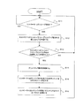
以下、画像形成装置13が実行する情報処理を説明する。図6は、画像形成装置13が実行する情報処理を示すフローチャート図である。例えば、画像形成装置13のメインコントローラ部5501のCPUが、図6のフローチャートに基づくプログラムに従って、この情報処理を行う。ユーザが印刷を指示すると、ホストPC11(IPアドレスを192.168.0.2と仮定する)はプリンタコントローラ12に対して、プリントジョブを受信するように要求する。このときにホストPC11によって送信されるプリントジョブ要求のsourceアドレスは192.168.0.2であって、destinationアドレスは192.168.0.3である。しかし、プリンタコントローラ12はスリープ状態であるため、このプリントジョブ要求を受信することができない。
Hereinafter, information processing executed by the
そこで、画像形成装置13は、プリンタコントローラ12がスリープ状態であるかを否かを判断する(ステップS11)。プリンタコントローラ12がスリープ状態である場合(ステップS11でYes)には、画像形成装置13はプリンタコントローラ12宛てのプリントジョブ要求をネットワーク上で監視し始める。そして、画像形成装置13は、プリントジョブ要求がホストPC11からプリンタコントローラ12へ送信されたかどうかを調べる(ステップS12)。そして、画像形成装置13は、プリントジョブ要求の送信が検知されたかどうかを判断する(ステップS13)。プリントジョブ要求の送信が検知された場合には、画像形成装置13はそれを受信する(ステップS14)。画像形成装置13がプリントジョブ要求の送信を検知しなかった場合には、画像形成装置13はステップS11へ戻る。
Therefore, the
プリンタコントローラ12に対してプリントジョブ要求が送信されたことを検知した画像形成装置13は、プリントジョブ要求のsourceアドレスに基づいてプリントジョブ要求の送信元であるホストPC11のIPアドレスを認識している。そのため、画像形成装置13はそのIPアドレス宛てにデータを送信することが可能となる。よって、画像形成装置13は、プリンタコントローラ12がスリープ中であることをユーザに知らせる画面21(図2)をホストPC11に表示するためのコマンドを、ホストPC11に対して、送信する(ステップS15)。コマンドのsourceアドレスは192.168.0.4であって、destinationアドレスは192.168.0.2である。
The
例えば、画像形成装置13は、図2が示す画面を表示するようなHTML(Hyper Text Markup Lanauge)データをホストPC11に対して送信する。すると、ホストPC11のウェブブラウザは、当該HTMLデータに従って、図2に示すような画面を表示する。この時、図2に示すように、プリンタコントローラ12がスリープ状態からスタンバイ状態に復帰するまでの時間を表示することによって、復帰するまでに必要な時間をユーザに知らせることも可能となる。
For example, the
それと同時に、画像形成装置13は、プリンタコントローラ12を印刷可能なスタンバイ状態にするためのコマンドをプリンタコントローラ12に対して専用ケーブルを介して送信する(ステップS16)。プリンタコントローラ12はこのデータを受信し、スタンバイ状態への移行作業を開始する。
At the same time, the
スタンバイ状態では、電力がプリンタコントローラ12の主要部に供給され、省電力状態は解除される。
In the standby state, power is supplied to the main part of the
次に、ホストPC11が実行する情報処理を説明する。図7は、ホストPC11が実行する情報処理を示すフローチャートである。ユーザが印刷を指示すると、ホストPC11はプリンタコントローラ12に対して、プリントジョブ要求を送信する(ステップS21)。なお、プリントジョブ要求の送信元を示すIPアドレスは192.168.0.2で、送信先を示すIPアドレスは192.168.0.3である。次に、ホストPC11は、画面21を表示するためのコマンドが送信されてきたかを判断する(ステップS22)。ホストPC11は、当該コマンドが送信されてきた場合には、受信したデータに基づいて図2に示す画面21を表示する。それとともに、プリンタコントローラ12が印刷可能なスタンバイ状態となると、ホストPC11は、ユーザが再度印刷を指示するのに従って、プリントジョブ要求をプリンタコントローラ12へ再送する(ステップS23)。その後、ホストPC11はプリンタコントローラ12へプリントジョブを送信する(ステップS24)。プリンタコントローラ12がそのプリントジョブに対して所定の処理を行った後、画像形成装置13はそのプリントジョブに基づく印刷を実行する。
Next, information processing executed by the host PC 11 will be described. FIG. 7 is a flowchart showing information processing executed by the host PC 11. When the user instructs printing, the host PC 11 transmits a print job request to the printer controller 12 (step S21). The IP address indicating the transmission source of the print job request is 192.168.0.2, and the IP address indicating the transmission destination is 192.168.0.3. Next, the host PC 11 determines whether a command for displaying the
<第2の実施形態>
次に、本発明の第2の実施形態として、ホストPCがプリントジョブ要求をスリープ状態のプリンタコントローラへ送信した場合、画像形成装置がホストPCへ特定のウェブページを送信する場合の実施形態を説明する。なお、ウェブページは、HTMLなどで記述されてデータであって、ホストPCのウェブブラウザは当該データに従ってウェブページを表示する。
<Second Embodiment>
Next, as a second embodiment of the present invention, an embodiment in which the image forming apparatus transmits a specific web page to the host PC when the host PC transmits a print job request to the printer controller in the sleep state will be described. To do. The web page is data described in HTML or the like, and the web browser of the host PC displays the web page according to the data.
本発明の第2の実施形態に係る画像形成システムの構成は、上記第1の実施形態と同様である。プリンタコントローラ12は画像形成装置13に接続されている。プリンタコントローラ12はスリープ状態に入る前に、画像形成装置13に対して、スリープ状態に入ることを知らせるためのデータを送信する。このデータによって画像形成装置13は、プリンタコントローラ12がスリープ状態に入ることを知ることが可能となる。
The configuration of the image forming system according to the second embodiment of the present invention is the same as that of the first embodiment. The
ユーザが印刷を実行すると、ホストPC11からプリンタコントローラ12に対して、プリントジョブを受信するように要求をする。しかし、プリンタコントローラ12はスリープ状態であるため、このプリントジョブ要求を受信することができない。
When the user executes printing, the host PC 11 requests the
ホストPCのウェブブラウザは、画像形成装置13へhttp要求を送信することができる。その要求に対して、画像形成装置13はプリンタコントローラ12が印刷要求を受けた時点でスリープ状態であることを表示したウェブページをホストPC11へ送信する。このウェブページによって、プリンタコントローラ12がスリープ状態であることを知らせることができる。この時、プリンタコントローラ12がスリープ状態からスタンバイ状態に復帰するまでの時間を表示することによって、復帰するまでに必要な時間をユーザに知らせることも可能となる。
The web browser of the host PC can send an http request to the
それと同時に、画像形成装置13はプリンタコントローラ12と画像形成装置13を接続する専用ケーブルを利用して、プリンタコントローラ12を印刷可能なスタンバイ状態にするためのデータを送信する。プリンタコントローラ12はこのデータを受信し、スタンバイ状態への移行作業を開始する。
At the same time, the
プリンタコントローラ12が印刷可能なスタンバイ状態となると、ユーザは再度印刷を指示し、ホストPC11からプリンタコントローラ12へプリントジョブが送信され、画像形成装置13はそのプリントジョブに基づく印刷を実行する。
When the
<第3の実施形態>
次に、本発明の第3の実施形態について説明する。
上記第1、第2の実施形態においては、ホストPCがプリントジョブ要求をスリープ状態のプリンタコントローラへ送信した場合、画像形成装置が、プリンタコントローラがスリープ状態であることを示す情報をホストPCに送信する例を説明した。本発明の第3の実施形態では、画像形成装置がコントローラがスリープ状態であることをユーザに伝えた上で、スタンバイ状態の他のコントローラを検索可能にする例を説明する。
<Third Embodiment>
Next, a third embodiment of the present invention will be described.
In the first and second embodiments, when the host PC transmits a print job request to the printer controller in the sleep state, the image forming apparatus transmits information indicating that the printer controller is in the sleep state to the host PC. The example to do was explained. In the third embodiment of the present invention, an example will be described in which the image forming apparatus informs the user that the controller is in the sleep state, and can search for another controller in the standby state.
図3は、本発明の第3の実施形態に係る画像形成システムの構成を示す図である。図3では、ホストPC11、プリンタコントローラ12、画像形成装置13、プリンタコントローラ34及び画像形成装置35がLANに接続されている。
FIG. 3 is a diagram showing a configuration of an image forming system according to the third embodiment of the present invention. In FIG. 3, the host PC 11,
図8は、第3の実施形態における画像形成装置13が実行する情報処理を示すフローチャート図である。例えば、画像形成装置13のメインコントローラ部のCPUが、図8のフローチャートに基づくプログラムに従って、この情報処理を行う。
FIG. 8 is a flowchart illustrating information processing executed by the
画像形成装置13は、プリンタコントローラ12がスリープ状態であるかを否かを判断する(ステップS31)。プリンタコントローラ12がスリープ状態である場合(ステップS31でYes)には、画像形成装置13はプリンタコントローラ12宛てのプリントジョブ要求をネットワーク上で監視し始める。そして、画像形成装置13は、プリントジョブ要求がホストPC11からプリンタコントローラ12へ送信されたかどうかを調べる(ステップS32)。さらに、画像形成装置13は、プリントジョブ要求の送信が検知されたかどうかを判断する(ステップS33)。プリントジョブ要求の送信が検知された場合には、画像形成装置13はそれを受信する(ステップS34)。画像形成装置13がプリントジョブ要求の送信を検知しなかった場合には、画像形成装置13はステップS31へ戻る。
The
ホストPCに複数のコントローラが接続されている場合、プリントジョブの送信先であるコントローラがスリープ状態であっても、その他にスタンバイ状態のコントローラが接続されている可能性がある。そこで、画像形成装置13が、ネットワーク上にスタンバイ状態のコントローラが他に接続されているかどうかを判断する(ステップS35)。図3のように、プリンタコントローラ12がスリープ状態、プリンタコントローラ34がスタンバイ状態であった場合、プリンタコントローラ12がスタンバイ状態になるのを待つという第1の印刷方法が考えられる。もしくは、すでにスタンバイ状態のプリンタコントローラ34へプリントジョブを送信するという第2の印刷方法が考えられる。
When a plurality of controllers are connected to the host PC, there is a possibility that another controller in the standby state may be connected even if the controller to which the print job is sent is in the sleep state. Therefore, the
そこで、スタンバイ状態のコントローラが他にない場合には、画像形成装置13は、画面21(図2)をホストPC11に表示するためのコマンドを、ホストPC11に対して送信する(ステップS36)。プリンタコントローラ12に対してプリントジョブ要求が送信されたことを検知した画像形成装置13は、プリントジョブ要求のsourceアドレスに基づいてプリントジョブ要求の送信元であるホストPC11のIPアドレスを認識している。そのため、画像形成装置13はそのIPアドレス宛てにデータを送信することが可能となる。コマンドのsourceアドレスは192.168.0.4であって、destinationアドレスは192.168.0.2である。
Therefore, if there is no other controller in the standby state, the
例えば、画像形成装置13は、図2が示す画面を表示するようなHTML(Hyper Text Markup Lanauge)データをホストPC11に対して送信する。すると、ホストPC11のウェブブラウザは、当該HTMLデータに従って、図2に示すような画面を表示する。この時、図2に示すように、プリンタコントローラ12がスリープ状態からスタンバイ状態に復帰するまでの時間を表示することによって、復帰するまでに必要な時間をユーザに知らせることも可能となる。
For example, the
それと同時に、画像形成装置13は、プリンタコントローラ12を印刷可能なスタンバイ状態にするためのコマンドをプリンタコントローラ12に対して専用ケーブルを介して送信する(ステップS37)。プリンタコントローラ12はこのデータを受信し、スタンバイ状態への移行作業を開始する。
At the same time, the
スタンバイ状態のコントローラが他にある場合には、画像形成装置13は、図4が示す検索画面をホストPC11に表示させるためのデータをホストPC11に対して送信する(ステップS38)。ホストPC11上では、このデータに基づいて検索画面が表示される。図4は検索画面41を示す図である。この検索画面では、スリープ状態であるプリンタコントローラ12をスタンバイ状態にすることをユーザは選択できる。または、プリンタコントローラ12以外にスタンバイ状態のプリンタコントローラが接続されているかを検索することをユーザは選択できる。
If there is another controller in the standby state, the
画像形成装置13は、以下の選択情報に基づいて、スタンバイ状態のコントローラを検索するか否かを判断する(ステップS39)。スリープ状態であるプリンタコントローラ12をスタンバイ状態にすることをユーザが選択した場合(ユーザが選択ボタン42をクリックした場合)は、その旨を示す選択情報が画像形成装置13に対して送信される。従って、画像形成装置13は、スタンバイ状態のコントローラを検索しないと判断して、プリンタコントローラ12を印刷可能なスタンバイ状態にするためのデータをプリンタコントローラ12に専用ケーブルを介して送信する(ステップS37)。プリンタコントローラ12はこのデータを受信し、スタンバイ状態への移行作業を開始する。
The
図4が示す検索画面で、検索結果を表示することをユーザが選択した場合(ユーザが選択ボタン43をクリックした場合)は、その旨の選択情報が画像形成装置13に対して送信される。従って、画像形成装置13は、スタンバイ状態のコントローラを検索すると判断して、ホストPC11に接続されている他のプリンタコントローラを検索する。そして、画像形成装置13は、図5が示す画面をホストPC11に表示するためのコマンドをホストPC11へ送信する(ステップS40)。
When the user selects to display the search result on the search screen shown in FIG. 4 (when the user clicks the selection button 43), selection information to that effect is transmitted to the
図5の画面では、スタンバイ状態のプリンタコントローラ一覧(図5の51)及びプリントジョブの送信先としてプリンタコントローラ34を選択できるボタン(図5の52)が表示される。プリンタコントローラ34がスタンバイ状態であった時、ホストPCはプリンタコントローラ34がスタンバイ状態であることを表示し、プリンタコントローラ34にプリントジョブを送信することが可能となる。ユーザはプリントジョブの送信先としてプリンタコントローラ34を選択し(ユーザは、選択ボタン52をクリック)、再度印刷を指示できる。ホストPC11からプリンタコントローラ34へプリントジョブが送信され、プリンタコントローラ34が接続されている画像形成装置35はそのプリントジョブに基づく印刷を実行する。
In the screen of FIG. 5, a list of printer controllers in the standby state (51 in FIG. 5) and a button (52 in FIG. 5) that can select the
上記実施形態によれば、プリンタコントローラがスリープ状態である時に、ホストPCから印刷要求が送信された場合でも、画像形成装置がホストPCに対してプリンタコントローラがスリープ状態であることを通知することが可能となる。プリンタコントローラがスリープ状態であることをユーザに知らせることができるため、プリンタコントローラはスリープ状態に移ることが可能になり、プリンタコントローラの消費電力を抑えることかできる。尚、本発明は、上述した画像形成装置による通知処理等の特徴的な処理を他の情報処理装置に行わせるように構成することも可能である。 According to the embodiment, even when a print request is transmitted from the host PC when the printer controller is in the sleep state, the image forming apparatus can notify the host PC that the printer controller is in the sleep state. It becomes possible. Since the user can be notified that the printer controller is in the sleep state, the printer controller can enter the sleep state, and the power consumption of the printer controller can be suppressed. The present invention can also be configured to cause other information processing apparatuses to perform characteristic processing such as notification processing by the image forming apparatus described above.
また、本発明の目的は、前述した実施形態の機能を実現するソフトウェアのプログラムコードを記録した記憶媒体を、システム或いは装置に供給することによっても達成されることは言うまでもない。そのシステム或いは装置のコンピュータ(またはCPUやMPU)が記憶媒体に格納されたプログラムコードを読み出し実行することによって、本発明の目的が達成される。 It goes without saying that the object of the present invention can also be achieved by supplying a storage medium storing software program codes for realizing the functions of the above-described embodiments to a system or apparatus. The object of the present invention is achieved by the computer (or CPU or MPU) of the system or apparatus reading and executing the program code stored in the storage medium.
この場合、記憶媒体から読み出されたプログラムコード自体が前述した実施形態の機能を実現することになり、プログラムコード自体及びそのプログラムコードを記憶した記憶媒体は本発明を構成することになる。 In this case, the program code itself read from the storage medium realizes the functions of the above-described embodiments, and the program code itself and the storage medium storing the program code constitute the present invention.
プログラムコードを供給するための記憶媒体としては、例えば、フレキシブルディスク、ハードディスク、光ディスク、光磁気ディスク、CD−ROM、CD−R、磁気テープ、不揮発性のメモリカード、ROM等を用いることができる。 As a storage medium for supplying the program code, for example, a flexible disk, a hard disk, an optical disk, a magneto-optical disk, a CD-ROM, a CD-R, a magnetic tape, a nonvolatile memory card, a ROM, or the like can be used.
また、コンピュータが読み出したプログラムコードを実行することにより、前述した実施形態の機能が実現されるだけでない。コンピュータ上で稼動しているOS(基本システム或いはオペレーティングシステム)などがそのプログラムコードの指示に基づき実際の処理の一部又は全部を行い、その処理によって前述した実施形態の機能が実現されても良い。 In addition, the functions of the above-described embodiments are not only realized by executing the program code read by the computer. An OS (basic system or operating system) running on the computer may perform part or all of the actual processing based on an instruction of the program code, and the functions of the above-described embodiments may be realized by the processing. .
さらに、記憶媒体から読み出されたプログラムコードが、コンピュータに挿入された機能拡張ボードやコンピュータに接続された機能拡張ユニットに備わるメモリに書込まれて、前述した実施形態の機能が実現されても良い。その場合、その機能拡張ボードや機能拡張ユニットに備わるCPU等がそのプログラムコードの指示に基づき実際の処理の一部又は全部を行い、その処理によって前述した実施形態の機能が実現される。 Further, the program code read from the storage medium is written in a memory provided in a function expansion board inserted into the computer or a function expansion unit connected to the computer, so that the functions of the above-described embodiments are realized. good. In that case, a CPU or the like provided in the function expansion board or function expansion unit performs part or all of the actual processing based on an instruction of the program code, and the functions of the above-described embodiments are realized by the processing.
11 ホストPC
12、34 プリンタコントローラ
13、35 画像形成装置
11 Host PC
12, 34
Claims (3)
前記印刷処理装置から送信される前記印刷データに基づいて印刷を実行する印刷手段と、
前記印刷処理装置が省電力状態であるかを判定する判定手段と、
前記外部装置からの前記印刷処理装置に対する印刷要求を監視する監視手段と、
前記判定手段により前記印刷処理装置が前記省電力状態であると判定され、前記監視手段により前記印刷処理装置に対する印刷要求が検知された場合、前記印刷処理装置が前記省電力状態から復帰するのに要する時間を前記外部装置に通知する通知手段と、
前記判定手段により前記印刷処理装置が前記省電力状態であると判定され、前記監視手段により前記印刷処理装置に対する印刷要求が検知された場合、前記印刷処理装置を前記省電力状態から復帰させるためのデータを前記印刷処理装置へ送信するデータ送信手段とを有することを特徴とする情報処理装置。 An information processing apparatus capable of communicating with a print processing apparatus that generates print data based on data received from an external apparatus,
Printing means for executing printing based on the print data transmitted from the print processing apparatus;
Determination means for determining whether the print processing apparatus is in a power saving state;
Monitoring means for monitoring a print request from the external device to the print processing device;
When the determination unit determines that the print processing apparatus is in the power saving state and the monitoring unit detects a print request to the print processing apparatus, the print processing apparatus returns from the power saving state. Notification means for notifying the external device of the time required;
When the determination unit determines that the print processing apparatus is in the power saving state, and the monitoring unit detects a print request to the print processing apparatus, the print processing apparatus is caused to return from the power saving state. An information processing apparatus comprising: data transmission means for transmitting data to the print processing apparatus.
前記通知手段は、前記検索手段により検索された前記他の印刷処理装置を示す情報を更に前記外部装置に通知することを特徴とする請求項1に記載の情報処理装置。 A search unit for searching for another print processing apparatus in a standby state other than the print processing apparatus;
The information processing apparatus according to claim 1 , wherein the notification unit further notifies the external apparatus of information indicating the other print processing apparatus searched by the search unit.
前記印刷処理装置から送信される前記印刷データに基づいて印刷を実行する印刷ステップと、
前記印刷処理装置が省電力状態であるかを判定する判定ステップと、
前記外部装置からの前記印刷処理装置に対する印刷要求を監視する監視ステップと、
前記判定ステップにより前記印刷処理装置が前記省電力状態であると判定され、前記監視ステップにより前記印刷処理装置に対する印刷要求が検知された場合、前記印刷処理装置が前記省電力状態から復帰するのに要する時間を前記外部装置に通知する通知ステップと、
前記判定ステップにより前記印刷処理装置が前記省電力状態であると判定され、前記監視ステップにより前記印刷処理装置に対する印刷要求が検知された場合、前記印刷処理装置を前記省電力状態から復帰させるためのデータを前記印刷処理装置へ送信するデータ送信ステップとを含むことを特徴とする情報処理方法。 An information processing method by an information processing device capable of communicating with a print processing device that generates print data based on data received from an external device,
A printing step for executing printing based on the print data transmitted from the print processing apparatus;
A determination step of determining whether the print processing apparatus is in a power saving state;
A monitoring step of monitoring a print request from the external device to the print processing device;
When the determination step determines that the print processing apparatus is in the power saving state, and the monitoring step detects a print request to the print processing apparatus, the print processing apparatus returns from the power saving state. A notification step of notifying the external device of the time required;
When the determination step determines that the print processing apparatus is in the power saving state, and the monitoring step detects a print request to the print processing apparatus, the print processing apparatus is caused to return from the power saving state. A data transmission step of transmitting data to the print processing apparatus.
Priority Applications (1)
| Application Number | Priority Date | Filing Date | Title |
|---|---|---|---|
| JP2005310425A JP4865296B2 (en) | 2004-10-26 | 2005-10-25 | Information processing apparatus and information processing method |
Applications Claiming Priority (3)
| Application Number | Priority Date | Filing Date | Title |
|---|---|---|---|
| JP2004311412 | 2004-10-26 | ||
| JP2004311412 | 2004-10-26 | ||
| JP2005310425A JP4865296B2 (en) | 2004-10-26 | 2005-10-25 | Information processing apparatus and information processing method |
Publications (3)
| Publication Number | Publication Date |
|---|---|
| JP2006155597A JP2006155597A (en) | 2006-06-15 |
| JP2006155597A5 JP2006155597A5 (en) | 2008-12-11 |
| JP4865296B2 true JP4865296B2 (en) | 2012-02-01 |
Family
ID=36633754
Family Applications (1)
| Application Number | Title | Priority Date | Filing Date |
|---|---|---|---|
| JP2005310425A Expired - Fee Related JP4865296B2 (en) | 2004-10-26 | 2005-10-25 | Information processing apparatus and information processing method |
Country Status (1)
| Country | Link |
|---|---|
| JP (1) | JP4865296B2 (en) |
Families Citing this family (7)
| Publication number | Priority date | Publication date | Assignee | Title |
|---|---|---|---|---|
| US20130003111A1 (en) * | 2011-06-30 | 2013-01-03 | Konica Minolta Laboratory U.S.A., Inc. | Method and system for network diagnostics which shows possible causes on a display of an image forming apparatus |
| JP5838862B2 (en) * | 2012-03-01 | 2016-01-06 | セイコーエプソン株式会社 | Network system, start control method, and network device |
| JP6225416B2 (en) * | 2012-11-19 | 2017-11-08 | 株式会社リコー | COMMUNICATION SYSTEM, COMMUNICATION DEVICE, AND COMMUNICATION METHOD |
| JP6184187B2 (en) * | 2013-06-14 | 2017-08-23 | キヤノン株式会社 | Information processing apparatus, information processing system, and information processing apparatus control method |
| JP6218515B2 (en) * | 2013-09-05 | 2017-10-25 | キヤノン株式会社 | Image forming apparatus, image forming apparatus control method, and program |
| JP6187077B2 (en) * | 2013-09-18 | 2017-08-30 | セイコーエプソン株式会社 | Printing apparatus, control system, and control method |
| CN106133678A (en) * | 2014-03-17 | 2016-11-16 | 李维-雷-舒普公司 | For controlling the method for the transmission of print data, client-side controller equipment, printing equipment and network |
Family Cites Families (11)
| Publication number | Priority date | Publication date | Assignee | Title |
|---|---|---|---|---|
| JP3325417B2 (en) * | 1995-02-08 | 2002-09-17 | 株式会社リコー | Image forming apparatus and its higher-level equipment |
| JP3846512B2 (en) * | 1995-10-30 | 2006-11-15 | 富士ゼロックス株式会社 | Image forming apparatus |
| NL1009817C2 (en) * | 1998-08-07 | 2000-02-08 | Oce Tech Bv | Manipulation of energy savings with imaging devices in a network system. |
| JP3139481B2 (en) * | 1998-11-30 | 2001-02-26 | 日本電気株式会社 | Network proxy response server, network system, and method for reducing power consumption of this network system |
| JP2002215352A (en) * | 2001-01-18 | 2002-08-02 | Minolta Co Ltd | Image processing device |
| JP3570996B2 (en) * | 2001-02-15 | 2004-09-29 | Necパーソナルプロダクツ株式会社 | Network relay device and network management system |
| US7050203B2 (en) * | 2001-06-08 | 2006-05-23 | Kabushiki Kaisha Toshiba | Composite apparatus and method for controlling entering of the sleep state |
| JP2003242055A (en) * | 2002-02-15 | 2003-08-29 | Canon Inc | Information processor, network system, information processing method, device control method, storage medium and program |
| JP2003256086A (en) * | 2002-03-06 | 2003-09-10 | Fuji Xerox Co Ltd | Information processor, network system and terminal unit |
| JP2003316557A (en) * | 2002-04-24 | 2003-11-07 | Canon Inc | Image formation system, image formation management method and its server |
| JP2004056258A (en) * | 2002-07-17 | 2004-02-19 | Canon Inc | Remote-control system, image processing apparatus, remote-control method, program, and storage medium |
-
2005
- 2005-10-25 JP JP2005310425A patent/JP4865296B2/en not_active Expired - Fee Related
Also Published As
| Publication number | Publication date |
|---|---|
| JP2006155597A (en) | 2006-06-15 |
Similar Documents
| Publication | Publication Date | Title |
|---|---|---|
| US7852501B2 (en) | Information processing apparatus and information processing method | |
| US7474431B2 (en) | Network printer having plural sleep modes | |
| JP4865296B2 (en) | Information processing apparatus and information processing method | |
| US8390839B2 (en) | Image formation system, information processor, and computer-readable recording medium to select apparatus for executing process | |
| US20120075651A1 (en) | Management system | |
| JP6312076B2 (en) | Image processing apparatus, image processing apparatus control method, and program | |
| JP2009075707A (en) | Information processor, equipment information management method for information processor, and program | |
| US20110176826A1 (en) | Printing control apparatus, printing control method, and program | |
| JP6132535B2 (en) | Printing system, printing control apparatus, printing control apparatus control method, and program | |
| US7265857B1 (en) | Medium where status information printing program is recorded, printer, print controller, status information printing method, and status information printing system | |
| JPH10217583A (en) | Print controlling method, its apparatus and printing system | |
| US7755789B2 (en) | Printing system and printing method to conserve developer | |
| JP2000357147A (en) | Information processing system, print system, information processor, and their control method | |
| JP2010277257A (en) | Program for starting printer | |
| JP2007136824A (en) | Printer, printing method, computer program, and storage medium | |
| JP4641355B2 (en) | Proxy processing management system, proxy processing management device, control method, and storage medium | |
| JPH09305334A (en) | Printer system and printer monitoring method | |
| JP3209857B2 (en) | PRINTING SYSTEM, PRINTING DEVICE, DATA DISTRIBUTION DEVICE, PRINTING SYSTEM CONTROL METHOD, PRINTING DEVICE CONTROL METHOD, AND DATA DISTRIBUTION DEVICE CONTROL METHOD | |
| KR0159722B1 (en) | Exhaustion warning method of printer consumption goods | |
| JP4254252B2 (en) | Printer control device and printer control program | |
| JP2006178767A (en) | Printing reservation system and its control method | |
| JP2005271512A (en) | Image forming apparatus and image forming apparatus system | |
| KR100630931B1 (en) | Image forming apparatus and printing system | |
| JP6136276B2 (en) | Image forming apparatus, power supply control apparatus, and control method for power supply control apparatus | |
| JP2007323263A (en) | Image formation system |
Legal Events
| Date | Code | Title | Description |
|---|---|---|---|
| A521 | Written amendment |
Free format text: JAPANESE INTERMEDIATE CODE: A523 Effective date: 20081024 |
|
| A621 | Written request for application examination |
Free format text: JAPANESE INTERMEDIATE CODE: A621 Effective date: 20081024 |
|
| A977 | Report on retrieval |
Free format text: JAPANESE INTERMEDIATE CODE: A971007 Effective date: 20100915 |
|
| A131 | Notification of reasons for refusal |
Free format text: JAPANESE INTERMEDIATE CODE: A131 Effective date: 20100921 |
|
| A521 | Written amendment |
Free format text: JAPANESE INTERMEDIATE CODE: A523 Effective date: 20101122 |
|
| A02 | Decision of refusal |
Free format text: JAPANESE INTERMEDIATE CODE: A02 Effective date: 20110607 |
|
| A521 | Written amendment |
Free format text: JAPANESE INTERMEDIATE CODE: A523 Effective date: 20110902 |
|
| A911 | Transfer to examiner for re-examination before appeal (zenchi) |
Free format text: JAPANESE INTERMEDIATE CODE: A911 Effective date: 20110912 |
|
| TRDD | Decision of grant or rejection written | ||
| A01 | Written decision to grant a patent or to grant a registration (utility model) |
Free format text: JAPANESE INTERMEDIATE CODE: A01 Effective date: 20111108 |
|
| A01 | Written decision to grant a patent or to grant a registration (utility model) |
Free format text: JAPANESE INTERMEDIATE CODE: A01 |
|
| A61 | First payment of annual fees (during grant procedure) |
Free format text: JAPANESE INTERMEDIATE CODE: A61 Effective date: 20111110 |
|
| FPAY | Renewal fee payment (event date is renewal date of database) |
Free format text: PAYMENT UNTIL: 20141118 Year of fee payment: 3 |
|
| FPAY | Renewal fee payment (event date is renewal date of database) |
Free format text: PAYMENT UNTIL: 20141118 Year of fee payment: 3 |
|
| LAPS | Cancellation because of no payment of annual fees |