JP4864450B2 - Vehicle driving support device - Google Patents
Vehicle driving support device Download PDFInfo
- Publication number
- JP4864450B2 JP4864450B2 JP2005368697A JP2005368697A JP4864450B2 JP 4864450 B2 JP4864450 B2 JP 4864450B2 JP 2005368697 A JP2005368697 A JP 2005368697A JP 2005368697 A JP2005368697 A JP 2005368697A JP 4864450 B2 JP4864450 B2 JP 4864450B2
- Authority
- JP
- Japan
- Prior art keywords
- dimensional object
- vehicle
- area
- driving support
- control
- Prior art date
- Legal status (The legal status is an assumption and is not a legal conclusion. Google has not performed a legal analysis and makes no representation as to the accuracy of the status listed.)
- Active
Links
Images


Description
本発明は、ステレオカメラ、単眼カメラ、ミリ波レーダ等で検出した前方の立体物に対して接触の可能性を判定し、運転支援制御する車両の運転支援装置に関する。 The present invention relates to a vehicle driving support apparatus that determines the possibility of contact with a front three-dimensional object detected by a stereo camera, a monocular camera, a millimeter wave radar, or the like, and performs driving support control.
近年、車両においては、車載したカメラ等により前方の走行環境を撮影し、前方立体物を認識して自車両との衝突の可能性を推定する様々な運転支援制御装置が提案され、実用化されている。こうした前方立体物と自車両との衝突の可能性を推定する装置においては、前方立体物の位置を正確に把握することが要求されるものの、カメラ、レーダ装置等による検出は、誤差を含むため、誤差を考慮して前方立体物の位置を特定する必要がある。 In recent years, various driving assistance control devices have been proposed and put into practical use in vehicles, in which a driving environment is photographed by a camera mounted on the vehicle, a three-dimensional object is recognized, and the possibility of a collision with the host vehicle is estimated. ing. In such an apparatus for estimating the possibility of a collision between the front three-dimensional object and the host vehicle, it is required to accurately grasp the position of the front three-dimensional object, but detection by a camera, a radar device, etc. includes an error. It is necessary to specify the position of the front three-dimensional object in consideration of errors.
例えば、特開2004−330950号公報では、レーダ装置で自車両の進行方向の先行車を検出し、自車両の予測進路に先行車が重なるオーバーラップ量を算出して、そのオーバーラップ量が所定値を超える時間が所定値を超えたときに、自車両が先行車に接触する可能性があると判断し、警報や自動制動よりなる安全装置を作動させる技術が開示されている。
すなわち、上述の特許文献1は、センサ誤差等の何らかの原因でオーバーラップ量が一時的に増大した場合に安全装置が作動して、ドライバに違和感を与えることを防止するものであるが、却って制御の遅れを招く可能性もある。障害物の検出誤差は、センサ自体の誤差以外にも走行環境や運転状態等により生じることがあり、こうした誤差を考慮し、吸収しながら運転支援制御をすることで初めて自然な制御となる。 That is, Patent Document 1 described above is intended to prevent the driver from feeling uncomfortable by operating the safety device when the overlap amount temporarily increases for some reason such as a sensor error. There is a possibility of causing a delay. Obstacle detection errors may occur depending on the driving environment and driving conditions in addition to the errors of the sensors themselves. Natural control is not performed until driving assistance control is performed while absorbing such errors.
本発明は上記事情に鑑みてなされたもので、障害物の検出誤差を適切に考慮し、吸収しながらレスポンス良く精度の高い運転支援制御を行うことができる車両の運転支援制御装置を提供することを目的としている。 The present invention has been made in view of the above circumstances, and provides a vehicle driving support control apparatus capable of performing driving support control with high response and high accuracy while properly absorbing and detecting obstacle detection errors. It is an object.
本発明は、自車進行路を基に走行領域を定め、該走行領域上に存在する立体物を検出する立体物検出手段と、自車両前方に予め設定した条件に応じて少なくとも統計処理による領域を設定する領域設定手段と、上記領域設定手段で設定した上記統計処理による領域に対する上記立体物の位置に応じて予め設定した制御を実行する制御実行手段とを備えた車両の運転支援装置であって、上記立体物検出手段は、上記立体物を自車両に対して接触する可能性を判定する判定対象として抽出すると共に、上記領域設定手段は、上記領域の左端と右端、及び、前端を、自車速と上記立体物の幅と上記立体物検出手段の種類と自車両の旋回動作の少なくとも何れかに応じて可変して、少なくとも統計処理で設定し、上記制御実行手段は、上記立体物と上記領域から接触確率を演算することを特徴としている。 The present invention provides a three-dimensional object detection means for detecting a three-dimensional object existing on the traveling area by determining a traveling area based on the traveling path of the own vehicle, and at least an area based on statistical processing according to a preset condition in front of the own vehicle. A vehicle driving support device comprising: an area setting means for setting a position; and a control execution means for executing a preset control in accordance with the position of the three-dimensional object with respect to the area determined by the statistical processing set by the area setting means. The three-dimensional object detection means extracts the three-dimensional object as a determination target for determining the possibility of contact with the host vehicle, and the area setting means determines the left end, the right end, and the front end of the area. Variable according to at least one of the own vehicle speed, the width of the three-dimensional object, the type of the three-dimensional object detection means, and the turning motion of the own vehicle, and set by at least statistical processing. Up It is characterized by computing the probability of contact from the area.
本発明による車両の運転支援制御装置は、障害物の検出誤差を適切に考慮し、吸収しながらレスポンス良く精度の高い運転支援制御を行うことが可能となる。 The vehicle driving support control apparatus according to the present invention can perform driving support control with high response and high accuracy while properly absorbing and detecting obstacle detection errors.
以下、図面に基づいて本発明の実施の形態を説明する。
図1乃至図7は本発明の実施の一形態を示し、図1は車両に搭載した運転支援制御装置の概略構成図、図2は運転支援制御プログラムのフローチャート、図3は接触確率演算式の設定ルーチンのフローチャート、図4は横方向中央値を設定する第1のゲインの特性マップの説明図、図5は前方向領域長さを設定する第3のゲインの特性マップの説明図、図6は制御ゲインを設定する第4のゲインの特性マップの説明図、図7は自車両前方に設定される接触確率演算式を用いた領域の概略説明図である。
Hereinafter, embodiments of the present invention will be described with reference to the drawings.
1 to 7 show an embodiment of the present invention, FIG. 1 is a schematic configuration diagram of a driving support control device mounted on a vehicle, FIG. 2 is a flowchart of a driving support control program, and FIG. FIG. 4 is an explanatory diagram of a first gain characteristic map for setting the lateral median, FIG. 5 is an explanatory diagram of a third gain characteristic map for setting the forward region length, and FIG. Is an explanatory diagram of a fourth gain characteristic map for setting a control gain, and FIG. 7 is a schematic explanatory diagram of a region using a contact probability calculation formula set in front of the host vehicle.
図1において、符号1は自動車等の車両(自車両)で、この車両1には、車両用運転支援制御装置2が搭載されている。この車両用運転支援制御装置2は、ステレオカメラ3、ステレオ画像認識装置4、制御ユニット5を有して主要に構成されており、この車両用運転支援制御装置2では、基本的に、後述の運転支援制御プログラムに従って制御され、前方立体物との接触確率(演算の詳細は後述する)に応じて、警報制御、及び、自動ブレーキ制御の何れかを実行する。
In FIG. 1, reference numeral 1 denotes a vehicle (host vehicle) such as an automobile, and a vehicle driving
すなわち、前方立体物との接触確率が低い場合はそのままとし、この状態から接触確率が高まるとモニタ6、或いは、スピーカ7より音声による警報を発生し(警報制御)、更にこの警報制御の状態から接触確率が高まると自動ブレーキ制御装置8に減速信号を出力して一定の自動ブレーキを作動させる(減速制御)。
That is, when the contact probability with the front three-dimensional object is low, it is left as it is, and when the contact probability is increased from this state, a sound alarm is generated from the
ステレオカメラ3は、ステレオ光学系として例えば電荷結合素子(CCD)等の固体撮像素子を用いた1組の(左右の)CCDカメラで構成され、これら左右のCCDカメラは、それぞれ車室内の天井前方に一定の間隔をもって取り付けられ、車外の対象を異なる視点からステレオ撮像し、撮像信号をステレオ画像認識装置4に出力する。
The
また、自車両1には、自車速Vownを検出する車速センサ9が設けられており、この自車速Vownは、ステレオ画像認識装置4と制御ユニット5とに出力される。 Further, the host vehicle 1 is provided with a vehicle speed sensor 9 for detecting the host vehicle speed Vown, and the host vehicle speed Vown is output to the stereo image recognition device 4 and the control unit 5.
ステレオ画像認識装置4は、ステレオカメラ3からの画像、車速センサ9からの自車速Vownが入力され、ステレオカメラ3からの画像に基づき自車両1前方の立体物データと白線データの前方情報を検出し、自車両1の進行路(自車進行路)を推定する(例えば、自車両1の運転状態、白線等に応じて推定する)。そして、この自車進行路を基に、走行領域を定め(例えば、自車進行路を中心とする左右1mの幅の領域)、この走行領域上の自車両1に最も近い立体物を、自車両1に対して接触する可能性を判定する判定対象として抽出する。更に、後述するように、予め設定した条件に応じて少なくとも統計処理による領域を設定し、この領域を接触確率演算式PPxzで表現し、この接触確率演算式PPxzを基に演算した接触確率PPを、制御ユニット5に出力する。
The stereo image recognition device 4 receives the image from the
ここで、ステレオ画像認識装置4における、ステレオカメラ3からの画像の処理は、例えば以下のように行われる。まず、ステレオカメラ3で撮像した自車両1前方のステレオ画像に対し、対応する位置のずれ量から三角測量の原理によって距離データを生成する。そして、この距離データを基に、周知のグルーピング処理や、予め記憶しておいた3次元的な道路形状データ、立体物データ等と比較し、白線データ、道路に沿って存在するガードレール、縁石等の側壁データ、車両や歩行者等の立体物データを抽出する。立体物データでは、立体物までの距離と、この距離の時間的変化(自車両1に対する相対速度)が求められ、特に、上述した走行領域上にある最も近い立体物が判定対象とする立体物として抽出され、接触確率演算式PPxzにより接触確率PPが演算される。
Here, the processing of the image from the
このように、ステレオ画像認識装置4は、立体物検出手段及び領域設定手段の機能を有して設けられている。 Thus, the stereo image recognition device 4 is provided with the functions of the three-dimensional object detection means and the area setting means.
制御ユニット5は、ステレオ画像認識装置4から接触確率PPが入力され、この接触確率PPが、予め設定しておいた閾値C1以上の場合にはスピーカ7より音声による警報を発生して警報制御を行い、更に、予め設定しておいた閾値C2(>C1)以上の場合には自動ブレーキ制御装置8に減速信号を出力して一定の自動ブレーキを作動させ、減速制御を行う。すなわち、制御ユニット5は、制御実行手段として設けられている。また、ステレオ画像認識装置4が有する接触確率演算式PPxzにより接触確率PPを演算する機能は制御実行手段を構成するものとなっている。 The control unit 5 receives the contact probability PP from the stereo image recognition device 4, and when the contact probability PP is equal to or higher than a preset threshold value C <b> 1, generates a sound alarm from the speaker 7 and performs alarm control. Further, when the threshold value is equal to or greater than a preset threshold value C2 (> C1), a deceleration signal is output to the automatic brake control device 8 to operate a certain automatic brake and perform deceleration control. That is, the control unit 5 is provided as control execution means. The function of calculating the contact probability PP by the contact probability calculation formula PPxz included in the stereo image recognition device 4 constitutes a control execution unit.
次に、車両用運転支援制御装置2で実行される本実施の形態による運転支援制御プログラムを、図2のフローチャートで説明する。
まず、ステップ(以下、「S」と略称)101で、必要パラメータ(画像情報、自車速Vown)の読み込みを行い、S102に進み、ステレオ画像認識装置4は、上述の如く立体物の認識処理を実行する。
Next, the driving support control program according to the present embodiment executed by the vehicle driving
First, in step (hereinafter abbreviated as “S”) 101, necessary parameters (image information, own vehicle speed Vown) are read, and the process proceeds to S102, where the stereo image recognition device 4 performs the three-dimensional object recognition process as described above. Execute.
次いで、S103に進み、ステレオ画像認識装置4は、自車進行路を基に設定した走行領域上の自車両1に最も近い立体物を、自車両1に対して接触する可能性を判定する判定対象として抽出する。 Next, the process proceeds to S103, and the stereo image recognition device 4 determines whether or not the three-dimensional object closest to the host vehicle 1 on the travel region set based on the host vehicle traveling path may come into contact with the host vehicle 1. Extract as target.
次に、S104に進むと、判定対象とする立体物が存在するか否か判定し、判定対象とする立体物が存在しない場合はそのままプログラムを抜け、存在する場合はS105に進む。 Next, when proceeding to S104, it is determined whether or not there is a three-dimensional object to be determined. If there is no three-dimensional object to be determined, the program is left as it is, and if there is a three-dimensional object, the process proceeds to S105.
S105では、後述する図3に示すフローチャートに従って、領域として接触確率演算式PPxzを設定する。尚、本実施の形態において用いられる座標系は、自車両1の左右(幅)方向をX座標、自車両1の上下方向をY座標、自車両1の前後方向をZ座標とする自車両1を基準とする実空間の3次元座標系を用いて各処理を行う。この場合、ステレオカメラ3を成す2台のCCDカメラの中央の真下の道路面を原点として、自車両1の右側がX軸の+側、自車両1の上方がY軸の+側、自車両1の前方がZ軸の+側として設定される。また、自車進行路は、f(z)として、zの関数として表すものとする。
In S105, the contact probability calculation formula PPxz is set as a region according to the flowchart shown in FIG. The coordinate system used in the present embodiment is the own vehicle 1 in which the left and right (width) direction of the own vehicle 1 is the X coordinate, the up and down direction of the own vehicle 1 is the Y coordinate, and the front and rear direction of the own vehicle 1 is the Z coordinate. Each processing is performed using a three-dimensional coordinate system in real space with reference to. In this case, with the road surface directly below the center of the two CCD cameras constituting the
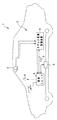
図3に示すフローチャートでは、まず、S201で、横方向中央値dx0(図7参照)を以下の(1)式により設定する。尚、図7では、理解を容易にするために自車進行路が直線(すなわち、x=0)の場合を例示するものである。
dx0=k1・k2・dx0b …(1)
ここで、dx0bは予め実験・計算等により設定しておいた横方向中央値dx0の基本値であり、k1は横方向中央値を設定する第1のゲイン、k2は横方向中央値を設定する第2のゲインである。
In the flowchart shown in FIG. 3, first, in S201, the lateral median dx0 (see FIG. 7) is set by the following equation (1). FIG. 7 illustrates a case where the own vehicle traveling path is a straight line (that is, x = 0) in order to facilitate understanding.
dx0 = k1, k2, dx0b (1)
Here, dx0b is a basic value of the lateral median value dx0 set in advance by experiments and calculations, k1 is a first gain for setting the lateral median value, and k2 is a lateral median value. This is the second gain.
横方向中央値を設定する第1のゲインk1は、例えば、図4に示すようなマップで可変設定され、判定対象の幅が広くなればなるほど大きな値に設定されるようになっている。すなわち、自動2輪車のような幅の狭いものが判定対象の場合は横方向中央値dx0は狭くなり、トラックのような幅の広いものが判定対象の場合は横方向中央値dx0は広く設定されて、接触確率PPとして大きな値が得られるようになっている。 The first gain k1 for setting the horizontal median value is variably set on a map as shown in FIG. 4, for example, and is set to a larger value as the width of the determination target becomes wider. That is, when a narrow object such as a motorcycle is a determination target, the lateral median value dx0 is narrow, and when a wide object such as a truck is a determination object, the lateral median value dx0 is set wide. Thus, a large value is obtained as the contact probability PP.
横方向中央値を設定する第2のゲインk2は、センサの種類に応じて変更されるゲインであり、例えば、カメラをセンサとして用いているのであれば大きな値に設定されるがレーザレーダ装置をセンサとして用いているのであれば、カメラの場合の値より小さい値が設定され、ミリ波レーダ装置をセンサとして用いているのであれば、レーザレーダ装置の場合の値よりさらに小さい値が設定される。これは、それぞれの装置をセンサとして用いた場合の幅方向寸法の精度(信頼度)を反映して決定されるものである。 The second gain k2 for setting the lateral median value is a gain that is changed according to the type of sensor. For example, if the camera is used as a sensor, the second gain k2 is set to a large value. If it is used as a sensor, a value smaller than the value for the camera is set, and if a millimeter wave radar device is used as the sensor, a value smaller than the value for the laser radar device is set. . This is determined by reflecting the accuracy (reliability) of the dimension in the width direction when each device is used as a sensor.
次いで、S202に進むと、横方向接触確率演算式PPxの設定が実行される。 Next, in S202, setting of the lateral contact probability calculation formula PPx is executed.
横方向接触確率演算式PPxは、以下の3つの領域((2)、(3)、(4)式)でそれぞれ設定される。尚、σx2は、予め、実験、計算等により求めておいた分散である。 The lateral contact probability calculation formula PPx is set in the following three regions (Equations (2), (3), and (4)), respectively. Note that σx 2 is a dispersion obtained in advance by experiment, calculation, or the like.
・x≦(f(z)−(dx0/2))の場合
PPx=(1/((2・π)1/2・σx))
・exp(−(x−(f(z)−(dx0/2)))2/(2・σx2)) …(2)
・(f(z)−(dx0/2))<x<(f(z)+(dx0/2))の場合
PPx=1.0 …(3)
・x≧(f(z)+(dx0/2))の場合
PPx=(1/((2・π)1/2・σx))
・exp(−(x−(f(z)+(dx0/2)))2/(2・σx2)) …(4)
すなわち、(2)式、(4)式はガウス分布の確率密度関数になっており、自車両前方の領域の左右端が統計処理による領域となっている。
When x ≦ (f (z) − (dx0 / 2)) PPx = (1 / ((2 · π) 1/2 · σx))
Exp (− (x− (f (z) − (dx0 / 2))) 2 / (2 · σx 2 )) (2)
When (f (z) − (dx0 / 2)) <x <(f (z) + (dx0 / 2)) PPx = 1.0 (3)
When x ≧ (f (z) + (dx0 / 2)) PPx = (1 / ((2 · π) 1/2 · σx))
Exp (− (x− (f (z) + (dx0 / 2))) 2 / (2 · σx 2 )) (4)
That is, Equations (2) and (4) are probability density functions of Gaussian distribution, and the left and right ends of the region ahead of the host vehicle are regions by statistical processing.
次に、S203に進むと、前方向領域長さdz0の値を、以下の(5)式により設定する。
dz0=k3・dz0b …(5)
ここで、dz0bは予め実験・計算等により設定しておいた前方向領域長さdz0の基本値であり、k3は前方向領域長さを設定する第3のゲインである。
Next, in S203, the value of the forward area length dz0 is set according to the following equation (5).
dz0 = k3 · dz0b (5)
Here, dz0b is a basic value of the forward area length dz0 set in advance by experiments and calculations, and k3 is a third gain for setting the forward area length.
前方向領域長さを設定する第3のゲインk3は、例えば、図5に示すようなマップで可変設定され、自車速Vownが高くなればなるほど、当然、前方に長い領域を設定するようになっている。 For example, the third gain k3 for setting the forward region length is variably set on a map as shown in FIG. 5, and as the vehicle speed Vown becomes higher, naturally, a longer region is set forward. ing.
次いで、S204に進むと、前方向接触確率演算式PPzの設定が実行される。 Next, in S204, the setting of the forward contact probability calculation formula PPz is executed.
前方向接触確率演算式PPzは、以下の2つの領域((6)、(7)式)でそれぞれ設定される。尚、σz2は、予め、実験、計算等により求めておいた分散である。 The forward contact probability calculation formula PPz is set in the following two regions (Equations (6) and (7)), respectively. Note that σz 2 is a dispersion obtained in advance by experiment, calculation, or the like.
・z≧dz0の場合
PPz=(1/((2・π)1/2・σz))
・exp(−(z−dz0)2/(2・σz2)) …(6)
・z<dz0の場合
PPz=1.0 …(7)
すなわち、(6)式はガウス分布の確率密度関数になっており、自車両前方の領域の前端が統計処理による領域となっている。
When z ≧ dz0, PPz = (1 / ((2 · π) 1/2 · σz))
Exp (-(z-dz0) 2 / (2 · σz 2 )) (6)
When z <dz0, PPz = 1.0 (7)
That is, Equation (6) is a probability density function of Gaussian distribution, and the front end of the area in front of the host vehicle is an area by statistical processing.
次に、S205に進むと、制御ゲインrmを以下の(8)式により設定する。
rm=k4・k5・k6・rmb …(8)
ここで、k4は制御ゲインを設定する第4のゲイン、k5は制御ゲインを設定する第5のゲイン、k6は制御ゲインを設定する第6のゲインである。
Next, in S205, the control gain rm is set by the following equation (8).
rm = k4 · k5 · k6 · rmb (8)
Here, k4 is a fourth gain for setting the control gain, k5 is a fifth gain for setting the control gain, and k6 is a sixth gain for setting the control gain.
制御ゲインを設定する第4のゲインk4は、例えば、図6に示すようなマップで可変設定され、判定対象の幅が広くなればなるほど大きな値に設定されるようになっている。すなわち、自動2輪車のような幅の狭いものが判定対象の場合は制御ゲインrmは狭くなり、トラックのような幅の広いものが判定対象の場合は制御ゲインrmは広く設定されて、接触確率PPとして大きな値が得られるようになっている。 The fourth gain k4 for setting the control gain is variably set on a map as shown in FIG. 6, for example, and is set to a larger value as the width of the determination target becomes wider. That is, when a narrow object such as a motorcycle is a determination target, the control gain rm is narrowed. When a wide object such as a truck is a determination target, the control gain rm is set wide and the contact gain is reduced. A large value can be obtained as the probability PP.
制御ゲインを設定する第5のゲインk5は、センサの種類により予め可変設定されるものであり、それぞれのセンサの精度に応じて設定され、例えば、判定対象の検出をカメラによって行った場合は0.8、ミリ波レーダ装置によって行った場合は0.9、カメラとミリ波レーダ装置の混合によって行った場合は1.0、…と設定される。 The fifth gain k5 for setting the control gain is variably set in advance according to the type of sensor, and is set according to the accuracy of each sensor. For example, when the detection target is detected by the camera, the fifth gain k5 is 0. .8, 0.9 is set for the millimeter wave radar device, 1.0 is set for the mixed camera and millimeter wave radar device.
また、制御ゲインを設定する第6のゲインk6は、ターンシグナルスイッチの作動状況に応じて可変設定され、ターンシグナルスイッチがONの場合は、ターンシグナルスイッチがOFFの場合より大きな予め設定しておいた値が設定される(例えば、ONの場合の70%)。すなわち、旋回する場合は、判定する領域を小さくして接触確率PPを小さくする方が好ましいためである。 The sixth gain k6 for setting the control gain is variably set according to the operating condition of the turn signal switch. When the turn signal switch is ON, it is set in advance larger than when the turn signal switch is OFF. Value is set (for example, 70% when ON). That is, when making a turn, it is preferable to reduce the contact probability PP by reducing the area to be determined.
そして、S206に進むと、接触確率演算式PPxzを以下の(9)式により設定する。
PPxz=PPx・PPz・rm …(9)
In S206, the contact probability calculation formula PPxz is set according to the following equation (9).
PPxz = PPx · PPz · rm (9)
すなわち、本実施の形態による接触確率演算式PPxzは、図7に示すように、領域の左右端、前端がガウス分布により形成され、判定対象を検出するセンサの種類、自車速Vown、判定対象の幅、旋回動作(ターンシグナルスイッチのON−OFF)により可変設定される。 That is, as shown in FIG. 7, the contact probability calculation formula PPxz according to the present embodiment is formed by a Gaussian distribution at the left and right ends and the front end of the region, and the type of sensor that detects the determination target, the vehicle speed Vown, and the determination target The width and turning operation (turn signal switch ON / OFF) are variably set.
再び、図2のフローチャートに戻り、S105で接触確率演算式PPxzの設定を上述の如く行った後、S106に進むと、接触確率PPの演算を行う。 Returning again to the flowchart of FIG. 2, after setting the contact probability calculation formula PPxz as described above in S105, the process proceeds to S106, where the contact probability PP is calculated.
これは、上述の(9)式に判定対象の幅中央の座標を代入することにより求める。すなわち、図7で説明すると、判定対象後部の座標(dxf,dzf)を代入することに求める。 This is obtained by substituting the coordinate of the center of the width of the determination target in the above equation (9). That is, as described with reference to FIG. 7, it is obtained by substituting the coordinates (dxf, dzf) of the determination target rear part.
尚、以上のS101〜S106の処理は、ステレオ画像認識装置4の側で行われる処理であり、以降のS107〜S110の処理は制御ユニット5の側で行われる処理となっている。 Note that the processes of S101 to S106 described above are processes performed on the stereo image recognition apparatus 4 side, and the subsequent processes of S107 to S110 are processes performed on the control unit 5 side.
S107では、S106で演算した接触確率PPと予め設定しておいた閾値C1との比較が行われ、接触確率PPが閾値C1より小さい場合(PP<C1の場合)はそのままプログラムを抜ける。 In S107, the contact probability PP calculated in S106 is compared with a preset threshold C1, and if the contact probability PP is smaller than the threshold C1 (in the case of PP <C1), the program is directly exited.
逆に、接触確率PPが閾値C1以上の場合(PP≧C1の場合)は、S108に進み、前方の判定対象(障害物)に接近していることを、例えば、予め録音しておいた音声により警告する。 Conversely, if the contact probability PP is equal to or greater than the threshold value C1 (when PP ≧ C1), the process proceeds to S108 and, for example, a prerecorded voice indicating that the vehicle is approaching the determination target (obstacle) ahead. To warn.
そして、S109に進み、接触確率PPと予め設定しておいた閾値C2(>C1)との比較を行い、接触確率PPが閾値C2より小さい場合(PP<C2の場合)はそのままプログラムを抜ける。 In step S109, the contact probability PP is compared with a preset threshold C2 (> C1). If the contact probability PP is smaller than the threshold C2 (in the case of PP <C2), the program is exited as it is.
逆に、接触確率PPが閾値C2以上の場合(PP≧C2の場合)は、S110に進み、予め設定した量のブレーキ量を付加させるように自動ブレーキ制御を実行させて、プログラムを抜ける。 Conversely, if the contact probability PP is greater than or equal to the threshold C2 (when PP ≧ C2), the process proceeds to S110, the automatic brake control is executed so as to add a preset amount of brake, and the program is exited.
このように本実施の形態によれば、単に判定対象とのオーバーラップ量により警報制御や自動ブレーキ制御をおこなうのではなく、統計的な領域と判定対象との位置関係を基に警報制御や自動ブレーキ制御をおこなうようになっているので、障害物の検出誤差を適切に考慮し、吸収しながらレスポンス良く精度の高い運転支援制御を行うことが可能となる。 As described above, according to the present embodiment, alarm control and automatic brake control are not simply performed based on the overlap amount with the determination target, but alarm control or automatic control is performed based on the positional relationship between the statistical area and the determination target. Since the brake control is performed, it is possible to perform driving support control with high response and high accuracy while appropriately absorbing and absorbing obstacle detection errors.
また、本実施の形態のように判定領域を統計的に設定するのとは逆に、判定対象自体を統計的に設定して演算することも考えられる。しかしながら、判定対象自体を統計的に設定して演算する場合では、判定対象の速度、距離等の多くの検出、演算パラメータが必要となり、却って誤差が大きくなる可能性もあり、演算量も増えて、レスポンスが悪化する可能性もある。これに対し、本実施の形態では、判定対象ではなく、領域の側に統計的要素を導入しているので、上述のような判定対象個々に対する演算等が必要なく、簡単に素早く演算結果を得ることができ、レスポンスの良い精度の高い制御が可能となる。 In contrast to statistically setting the determination region as in the present embodiment, it is also conceivable that the determination target itself is statistically set and calculated. However, when the calculation is performed with the determination target itself set statistically, many detection and calculation parameters, such as the speed and distance of the determination target, are required. On the other hand, the error may increase and the calculation amount increases. The response may be worse. On the other hand, in this embodiment, since the statistical element is introduced not on the determination target but on the side of the region, the above calculation for each determination target is not necessary, and the calculation result can be obtained easily and quickly. Therefore, accurate control with good response is possible.
尚、本実施の形態では、前方領域の左右両端と前端にガウス分布による領域を設定して制御するようにしているが、左端と右端と前端の少なくとも何れか(例えば、左右両端のみ)に設定するものであっても良い。 In this embodiment, an area based on a Gaussian distribution is set and controlled at both the left and right ends and the front end of the front area. It may be what you do.
また、本実施の形態では、接触確率を基に、警報制御と減速制御の両方ができる例で説明しているが、どちらか一方のみ行うものであっても良い。 In this embodiment, an example in which both alarm control and deceleration control can be performed based on the contact probability has been described, but only one of them may be performed.
更に、本実施の形態で提案する統計的要素を考慮した領域は、警報、減速制御の判定を行う領域として用いた場合の例で説明しているが、他に、先行車を判定する領域(前方車両が追従制御等に用いる先行車か否かを判定する領域)として用いることもできる。 Furthermore, although the region in consideration of the statistical elements proposed in the present embodiment has been described as an example in the case of using it as a region for determining warning and deceleration control, other regions for determining the preceding vehicle ( It can also be used as an area for determining whether the preceding vehicle is a preceding vehicle used for follow-up control or the like.
尚、本実施の形態では、先行車の認識をステレオカメラからの画像を基に行うようになっているが、他の技術、例えば、ミリ波レーダと単眼カメラからの情報を基に認識するものであっても良い。 In this embodiment, the preceding vehicle is recognized on the basis of the image from the stereo camera. However, other technologies, for example, recognition based on information from the millimeter wave radar and the monocular camera are performed. It may be.
1 自車両
2 車両用運転支援制御装置
3 ステレオカメラ
4 ステレオ画像認識装置(立体物検出手段、領域設定手段、制御実行手段)
5 制御ユニット(制御実行手段)
6 モニタ
7 スピーカ
8 自動ブレーキ制御装置
9 車速センサ
DESCRIPTION OF SYMBOLS 1
5 Control unit (control execution means)
6 Monitor 7 Speaker 8 Automatic brake control device 9 Vehicle speed sensor
Claims (4)
自車両前方に予め設定した条件に応じて少なくとも統計処理による領域を設定する領域設定手段と、
上記領域設定手段で設定した上記統計処理による領域に対する上記立体物の位置に応じて予め設定した制御を実行する制御実行手段と、
を備えた車両の運転支援装置であって、
上記立体物検出手段は、上記立体物を自車両に対して接触する可能性を判定する判定対象として抽出すると共に、
上記領域設定手段は、上記領域の左端と右端、及び、前端を、自車速と上記立体物の幅と上記立体物検出手段の種類と自車両の旋回動作の少なくとも何れかに応じて可変して、少なくとも統計処理で設定し、
上記制御実行手段は、上記立体物と上記領域から接触確率を演算する
ことを特徴とする車両の運転支援装置。 A three-dimensional object detecting means for determining a traveling area based on the own vehicle traveling path and detecting a three-dimensional object existing on the traveling area;
An area setting means for setting at least an area by statistical processing in accordance with a condition set in front of the host vehicle;
Control execution means for executing control preset according to the position of the three-dimensional object with respect to the area by the statistical processing set by the area setting means;
A vehicle driving support device comprising:
The three-dimensional object detection means extracts the three-dimensional object as a determination target for determining the possibility of contacting the host vehicle,
The region setting means can vary the left end, the right end, and the front end of the region according to at least one of the own vehicle speed, the width of the three-dimensional object, the type of the three-dimensional object detection means, and the turning operation of the own vehicle. , set at least statistical processing,
The vehicle driving support apparatus, wherein the control execution means calculates a contact probability from the solid object and the region.
Priority Applications (1)
| Application Number | Priority Date | Filing Date | Title |
|---|---|---|---|
| JP2005368697A JP4864450B2 (en) | 2005-12-21 | 2005-12-21 | Vehicle driving support device |
Applications Claiming Priority (1)
| Application Number | Priority Date | Filing Date | Title |
|---|---|---|---|
| JP2005368697A JP4864450B2 (en) | 2005-12-21 | 2005-12-21 | Vehicle driving support device |
Publications (2)
| Publication Number | Publication Date |
|---|---|
| JP2007172266A JP2007172266A (en) | 2007-07-05 |
| JP4864450B2 true JP4864450B2 (en) | 2012-02-01 |
Family
ID=38298752
Family Applications (1)
| Application Number | Title | Priority Date | Filing Date |
|---|---|---|---|
| JP2005368697A Active JP4864450B2 (en) | 2005-12-21 | 2005-12-21 | Vehicle driving support device |
Country Status (1)
| Country | Link |
|---|---|
| JP (1) | JP4864450B2 (en) |
Cited By (1)
| Publication number | Priority date | Publication date | Assignee | Title |
|---|---|---|---|---|
| CN107128303A (en) * | 2017-06-05 | 2017-09-05 | 北京汽车集团有限公司 | Vehicle collision avoidance method, device, storage medium, equipment, system and vehicle |
Families Citing this family (6)
| Publication number | Priority date | Publication date | Assignee | Title |
|---|---|---|---|---|
| EP2306423B1 (en) * | 2008-07-10 | 2013-04-10 | Mitsubishi Electric Corporation | Train-of-vehicle travel support device |
| DE102009045286A1 (en) | 2009-10-02 | 2011-04-21 | Robert Bosch Gmbh | Method for imaging the environment of a vehicle |
| JP5656732B2 (en) | 2011-05-02 | 2015-01-21 | 株式会社デンソー | Collision probability computation device and collision probability computation program |
| JP5824968B2 (en) * | 2011-08-24 | 2015-12-02 | 日産自動車株式会社 | Travel control device |
| KR101816317B1 (en) * | 2011-12-06 | 2018-01-09 | 현대자동차주식회사 | A dangerous vehicle detect system by calculation of collision probability |
| CN109677419B (en) * | 2018-12-29 | 2020-11-20 | 北京金万安汽车电子技术研发有限公司 | Method for triggering automatic emergency braking system based on prediction |
Family Cites Families (6)
| Publication number | Priority date | Publication date | Assignee | Title |
|---|---|---|---|---|
| JP2799375B2 (en) * | 1993-09-30 | 1998-09-17 | 本田技研工業株式会社 | Anti-collision device |
| JP3376863B2 (en) * | 1997-07-18 | 2003-02-10 | 株式会社デンソー | Vehicle ahead detection device |
| JP2001242242A (en) * | 2000-02-29 | 2001-09-07 | Hitachi Ltd | Millimeter-wave radar device with function for improving detecting performance |
| JP2002029346A (en) * | 2000-07-14 | 2002-01-29 | Hiroyuki Yokozawa | System for supporting drive of automobile, and recording medium recorded with program for supporting drive |
| JP4026400B2 (en) * | 2002-04-26 | 2007-12-26 | トヨタ自動車株式会社 | Vehicle control device |
| JP4184096B2 (en) * | 2003-01-15 | 2008-11-19 | 富士通テン株式会社 | Preceding vehicle estimation method |
-
2005
- 2005-12-21 JP JP2005368697A patent/JP4864450B2/en active Active
Cited By (1)
| Publication number | Priority date | Publication date | Assignee | Title |
|---|---|---|---|---|
| CN107128303A (en) * | 2017-06-05 | 2017-09-05 | 北京汽车集团有限公司 | Vehicle collision avoidance method, device, storage medium, equipment, system and vehicle |
Also Published As
| Publication number | Publication date |
|---|---|
| JP2007172266A (en) | 2007-07-05 |
Similar Documents
| Publication | Publication Date | Title |
|---|---|---|
| US11738744B2 (en) | Driving support apparatus | |
| JP5167051B2 (en) | Vehicle driving support device | |
| JP4615038B2 (en) | Image processing device | |
| JP5345350B2 (en) | Vehicle driving support device | |
| JP4980076B2 (en) | Vehicle driving support device | |
| WO2017111135A1 (en) | Travel assistance device and travel assistance method | |
| JP4864450B2 (en) | Vehicle driving support device | |
| JP2018067102A (en) | Vehicle control device | |
| JP4223320B2 (en) | Vehicle driving support device | |
| JP2019093764A (en) | Vehicle control device | |
| US20210394752A1 (en) | Traveling Control Device, Vehicle, and Traveling Control Method | |
| US20180265083A1 (en) | Collision avoidance device | |
| JP2008149860A (en) | Travel control device | |
| JP4850963B1 (en) | Vehicle driving support device | |
| JP7130580B2 (en) | Road surface detector | |
| JP3867685B2 (en) | VEHICLE DRIVE OPERATION ASSISTANCE DEVICE AND VEHICLE HAVING VEHICLE DRIVE OPERATION ASSISTANCE DEVICE | |
| WO2020148561A1 (en) | Driving assistance method and driving assistance device | |
| JP2003276538A (en) | Obstacle predicting device | |
| JP4872517B2 (en) | Obstacle recognition device | |
| JP4807753B2 (en) | Vehicle driving support device | |
| WO2021176825A1 (en) | Sensing system | |
| JP4628596B2 (en) | Vehicle driving support device | |
| JP6548147B2 (en) | Vehicle control device | |
| JP2008129871A (en) | Travelling environment estimating device | |
| JP6354646B2 (en) | Collision avoidance support device |
Legal Events
| Date | Code | Title | Description |
|---|---|---|---|
| A621 | Written request for application examination |
Free format text: JAPANESE INTERMEDIATE CODE: A621 Effective date: 20081029 |
|
| A977 | Report on retrieval |
Free format text: JAPANESE INTERMEDIATE CODE: A971007 Effective date: 20101014 |
|
| A131 | Notification of reasons for refusal |
Free format text: JAPANESE INTERMEDIATE CODE: A131 Effective date: 20101026 |
|
| A521 | Request for written amendment filed |
Free format text: JAPANESE INTERMEDIATE CODE: A523 Effective date: 20101220 |
|
| A131 | Notification of reasons for refusal |
Free format text: JAPANESE INTERMEDIATE CODE: A131 Effective date: 20110329 |
|
| A521 | Request for written amendment filed |
Free format text: JAPANESE INTERMEDIATE CODE: A523 Effective date: 20110523 |
|
| TRDD | Decision of grant or rejection written | ||
| A01 | Written decision to grant a patent or to grant a registration (utility model) |
Free format text: JAPANESE INTERMEDIATE CODE: A01 Effective date: 20111025 |
|
| A01 | Written decision to grant a patent or to grant a registration (utility model) |
Free format text: JAPANESE INTERMEDIATE CODE: A01 |
|
| A61 | First payment of annual fees (during grant procedure) |
Free format text: JAPANESE INTERMEDIATE CODE: A61 Effective date: 20111109 |
|
| FPAY | Renewal fee payment (event date is renewal date of database) |
Free format text: PAYMENT UNTIL: 20141118 Year of fee payment: 3 |
|
| R150 | Certificate of patent or registration of utility model |
Free format text: JAPANESE INTERMEDIATE CODE: R150 Ref document number: 4864450 Country of ref document: JP Free format text: JAPANESE INTERMEDIATE CODE: R150 |
|
| S531 | Written request for registration of change of domicile |
Free format text: JAPANESE INTERMEDIATE CODE: R313531 |
|
| R350 | Written notification of registration of transfer |
Free format text: JAPANESE INTERMEDIATE CODE: R350 |
|
| R250 | Receipt of annual fees |
Free format text: JAPANESE INTERMEDIATE CODE: R250 |
|
| R250 | Receipt of annual fees |
Free format text: JAPANESE INTERMEDIATE CODE: R250 |
|
| R250 | Receipt of annual fees |
Free format text: JAPANESE INTERMEDIATE CODE: R250 |
|
| S533 | Written request for registration of change of name |
Free format text: JAPANESE INTERMEDIATE CODE: R313533 |
|
| R350 | Written notification of registration of transfer |
Free format text: JAPANESE INTERMEDIATE CODE: R350 |
|
| R250 | Receipt of annual fees |
Free format text: JAPANESE INTERMEDIATE CODE: R250 |
|
| R250 | Receipt of annual fees |
Free format text: JAPANESE INTERMEDIATE CODE: R250 |
|
| R250 | Receipt of annual fees |
Free format text: JAPANESE INTERMEDIATE CODE: R250 |
|
| R250 | Receipt of annual fees |
Free format text: JAPANESE INTERMEDIATE CODE: R250 |
|
| R250 | Receipt of annual fees |
Free format text: JAPANESE INTERMEDIATE CODE: R250 |
|
| R250 | Receipt of annual fees |
Free format text: JAPANESE INTERMEDIATE CODE: R250 |
|
| R250 | Receipt of annual fees |
Free format text: JAPANESE INTERMEDIATE CODE: R250 |