JP4863246B2 - Heat shield and roof structure with heat shield - Google Patents
Heat shield and roof structure with heat shield Download PDFInfo
- Publication number
- JP4863246B2 JP4863246B2 JP2004305432A JP2004305432A JP4863246B2 JP 4863246 B2 JP4863246 B2 JP 4863246B2 JP 2004305432 A JP2004305432 A JP 2004305432A JP 2004305432 A JP2004305432 A JP 2004305432A JP 4863246 B2 JP4863246 B2 JP 4863246B2
- Authority
- JP
- Japan
- Prior art keywords
- heat shield
- heat
- roof
- eaves
- main body
- Prior art date
- Legal status (The legal status is an assumption and is not a legal conclusion. Google has not performed a legal analysis and makes no representation as to the accuracy of the status listed.)
- Expired - Fee Related
Links
Images


Description
本発明は、屋根の野地板の裏面に取り付けられる遮熱材本体と、この遮熱材本体に連続して屋根の軒先部に取り付けられる軒先側遮熱材とを備えた遮熱材および遮熱材を備えた屋根構造に関する。 The present invention relates to a heat shield and a heat shield provided with a heat shield main body attached to the back surface of the roof base plate and an eaves side heat shield attached to the eaves portion of the roof continuously to the heat shield main body. It relates to a roof structure with materials.
従来より、室内空間の断熱性を確保するために、天井板の上面にはグラスウール等の断熱材が敷き込まれている。また、小屋裏空間の換気のため、天井と屋根とが交差する取合部には通気スペースが設けられている。 Conventionally, a heat insulating material such as glass wool is laid on the upper surface of the ceiling board in order to ensure the heat insulating property of the indoor space. In addition, a ventilation space is provided at the joint where the ceiling and the roof intersect for ventilation of the hut space.
ところが、住宅の気密性および断熱性を向上させるために、天井板の上面に敷き込まれる断熱材の厚みを大きくすると、天井と屋根とが交差する部分が断熱材によって塞がれてしまい、小屋裏空間の換気のための通気スペースを確保できない場合があった。 However, if the thickness of the heat insulating material laid on the top surface of the ceiling plate is increased in order to improve the airtightness and heat insulating properties of the house, the portion where the ceiling and the roof intersect with each other is blocked by the heat insulating material. There was a case where a ventilation space for ventilation of the back space could not be secured.
そこで、野地板の裏側の隣り合う垂木間に、ダンボール、厚紙等の比較的硬質の紙や比較的軟質のプラスティック板等からなる通気用のスペーサーを設置することによって、天井板の上面に敷き込まれた断熱材の端部を押さえ込み、小屋裏空間の換気のための通気スペースを確保する技術が開発されている(例えば、特許文献1参照。)。
ところで、近年、室内空間において開放感を得るために、天井高を出来るだけ高く設定したいという要望がある。 By the way, in recent years, there is a demand for setting the ceiling height as high as possible in order to obtain a feeling of opening in the indoor space.
しかしながら、単に天井板を高くして天井高を確保するような場合、前記特許文献1のようなダンボール等からなる通気用のスペーサーが、天井板の上面に敷き込まれた断熱材によって圧迫され、通気スペースが塞がれてしまうおそれがあった。
However, in a case where the ceiling plate is simply raised to ensure the ceiling height, a ventilation spacer made of cardboard or the like as in
これに対して、前記通気用のスペーサーを圧迫しないように、天井板の上面に敷き込んだ断熱材を薄くして天井を高くする場合には、断熱効果を低減させてしまうおそれもあった。 On the other hand, when the heat insulating material laid on the upper surface of the ceiling plate is made thin so as not to press the ventilation spacer, the heat insulating effect may be reduced.
以上のような問題点に鑑みて、天井高を出来るだけ高く設定したとしても、天井板上面の断熱材によって通気スペースが塞がれてしまうおそれのない通気用のスペーサーの開発が望まれていた。 In view of the above problems, there has been a demand for the development of a ventilation spacer that prevents the ventilation space from being blocked by the heat insulating material on the top surface of the ceiling plate even if the ceiling height is set as high as possible. .
本発明の課題は、天井高を高く設定しても通気路を確保することができるとともに、滞りなく屋根の換気をすることができ、しかも、室内への熱の侵入を効率良く防ぐことができる遮熱材および遮熱材を備えた屋根構造を提供することを目的とする。 The problem of the present invention is that it is possible to secure a ventilation path even when the ceiling height is set high, to ventilate the roof without stagnation, and to efficiently prevent heat from entering the room. It aims at providing the roof structure provided with the heat insulating material and the heat insulating material.
本発明は、屋根10の野地板10aの棟側裏面に取り付けられる板状の遮熱材本体2と、この遮熱材本体2に連続して、前記屋根10の野地板10aの軒先部側裏面に取り付けられる軒先側遮熱材3とを備えた遮熱材1において、前記軒先側遮熱材3は、その厚さH2が前記遮熱材本体の厚さH1よりも大きくなるように形成されることによって、前記遮熱材本体2の表面より前記屋根10の野地板10aの裏面からの高さが高い表層部4を備えており、この表層部4に、前記屋根の軒側から棟側に向けて貫通する通気路5が形成されており、前記軒先側遮熱材3は、建物躯体の外壁パネル11の上方及びこれに隣接する天井断熱材12bの縁部の上方に位置するように設置されていることを特徴とする。
The present invention is a plate-shaped heat shield
本発明によれば、前記軒先側遮熱材3は、その厚さH2が前記遮熱材本体2の厚さH1よりも大きくなるように形成されることによって、前記遮熱材本体2の表面より前記屋根10の野地板10aの裏面からの高さが高い表層部4を備えており、この表層部4に、前記屋根10の軒側から棟側に向けて貫通する通気路5が形成されていることから、この通気路5を前記遮熱材本体2によって塞がれることがなく、また、従来とは異なり、天井高を高く設定することで天井板上面の断熱材に圧迫されたとしても、この通気路5を塞がれることなく確保することができるので、通気路5に空気を通過させて滞りなく換気することで屋根10の熱を放熱することができ、しかも、前記遮熱材本体2および軒先側遮熱材3自体の遮熱効果との相乗効果によって、室内B1への熱の進入を効率良く防ぐことができる。
According to the present invention, the eaves-end
本発明の遮熱材によれば、この遮熱材の軒先側遮熱材は、その厚さが前記遮熱材の遮熱材本体の厚さよりも大きくなるように形成されることによって、前記遮熱材本体の表面より屋根の野地板の裏面からの高さが高い表層部を備えており、この表層部に、前記屋根の軒側から棟側に向けて貫通する通気路が形成されていることから、この通気路を前記遮熱材本体によって塞がれることがなく、また、従来とは異なり、天井高を高く設定することで天井板上面の断熱材に圧迫されたとしても、この通気路を塞がれることなく確保することができるので、通気路に空気を通過させて滞りなく換気することで屋根の熱を放熱することができ、しかも、前記遮熱材本体および軒先側遮熱材自体の遮熱効果との相乗効果によって、室内への熱の進入を効率良く防ぐことができる。 According to the heat shield material of the present invention, the eaves side heat shield material of the heat shield material is formed so that the thickness thereof is larger than the thickness of the heat shield material body of the heat shield material. It has a surface layer part whose height from the back side of the roof base plate is higher than the surface of the heat shield body, and an air passage that penetrates from the eave side of the roof toward the ridge side is formed in this surface layer part. Therefore, the air passage is not blocked by the main body of the heat shield material, and unlike the conventional case, even if the ceiling plate is set to a high ceiling and pressed by the heat insulating material on the top surface of the ceiling plate, Since the air passage can be secured without being blocked, the heat of the roof can be dissipated by allowing air to pass through the air passage and ventilating without any delay, and the heat shield main body and the eaves side shield. The synergistic effect with the thermal insulation effect of the thermal material itself helps to enter the heat into the room. It is possible to prevent well.
また、このような遮熱材を備えた屋根構造によれば、前記野地板の裏面全体の遮熱効果を向上させることができるとともに、前記軒先側遮熱材による屋根全体の熱の放熱効果を向上させることができ、しかも、これら遮熱効果と放熱効果との相乗効果によって、屋根全体における室内への熱の進入を効率良く防ぐことが可能となる。 Moreover, according to the roof structure provided with such a heat shielding material, the heat shielding effect of the entire back surface of the field board can be improved, and the heat radiation effect of the entire roof by the eaves side heat shielding material can be improved. In addition, the synergistic effect of the heat shielding effect and the heat dissipation effect can efficiently prevent heat from entering the room in the entire roof.
以下、図面を参照して本発明に係る遮熱材1および遮熱材1を備えた屋根構造Aの実施の形態について説明する。
Hereinafter, with reference to drawings, embodiment of roof structure A provided with
なお、本実施の形態の屋根構造Aおよび、この屋根構造Aを上部に設けるべき建物躯体Bはパネル工法によって構築される。 In addition, the roof structure A of this Embodiment and the building frame B which should provide this roof structure A in the upper part are constructed | assembled by a panel construction method.
[第1の実施の形態]
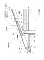
本実施の形態の遮熱材1は、図1に示すように、屋根10の野地板10aの裏面に取り付けられる遮熱材本体2と、この遮熱材本体2に連続して屋根10の軒先部10bに取り付けられる軒先側遮熱材3とを備えたものであり、
前記軒先側遮熱材3は、その厚さH2が前記遮熱材本体2の厚さH1よりも大きくなるように形成されことによって、前記遮熱材本体2の表面より前記屋根10の野地板10aの裏面からの高さが高い表層部4を備えており、この表層部4には、前記屋根10の軒側から棟側に向けて貫通する通気路5が形成されている。
[First Embodiment]
As shown in FIG. 1, the
The eaves-
また、本実施の形態の屋根10は、建築用屋根パネル10によって構成されており、この建築用屋根パネル10は、框材10d、10eを矩形枠状に組み立ててなる矩形枠10cの上面に、野地板10aとなる面材10aを取り付けて形成されている。
Moreover, the roof 10 of this Embodiment is comprised by the roof panel 10 for construction, and this roof panel 10 for construction is on the upper surface of the
このような建築用屋根パネル10が用いられることによって、工場等で、予め遮熱材1を取り付けておくことができるので、作業効率を向上させることができて好ましい。また、前記建物躯体Bが、この建築用屋根パネル10と同質のパネルで構成されたものである場合に、これら建築用屋根パネル10と建物躯体Bとを容易に連結することができる。
Use of such a building roof panel 10 is preferable because the
なお、本実施の形態の屋根構造Aおよび建物躯体Bは、建物の構成要素を予め工場にてパネル化しておき、施工現場でこれらのパネルを組み立てて構築するパネル工法で構築されるが、従来の軸組工法や壁式工法の木造、鉄骨造、鉄筋コンクリート造等の建物にも適用することができる。上述のようにパネル工法によって構築するが、これに限られるものではなく、例えば、軸組工法等でも良く、本発明の趣旨を逸脱しない範囲で適宜変更可能である。 In addition, the roof structure A and the building frame B of the present embodiment are constructed by a panel method in which building components are panelized at a factory in advance, and these panels are assembled and constructed at a construction site. This can also be applied to buildings such as wooden structures, steel structures, and reinforced concrete structures. Although it is constructed by the panel method as described above, the present invention is not limited to this. For example, a shaft assembling method or the like may be used and can be appropriately changed without departing from the gist of the present invention.
また、本実施の形態の建物躯体Bは、天井12直下の室内B1の天井高が高く設定されており、この室内空間B1において、例えば吹抜け空間のような広々とした開放感が得られるように構成されている。
In addition, the building frame B of the present embodiment is set so that the ceiling height of the room B1 directly below the
前記遮熱材本体2は、矩形状に形成された板材であり、図1に示すように、前記建築用屋根パネル10を構成する面材10aの裏面に取り付けられている。すなわち、建築用屋根パネル10の棟(図示せず)に至る範囲にわたって取り付けられており、後述する軒先側遮熱材3が取り付けられていない部位において、この遮熱材本体2が取り付けられ、建築用屋根パネル10の遮熱効果を向上させている。
The heat
なお、この板材としては、グラスウールやロックウール等の無機繊維状物質を板状に固めて成形した繊維系断熱ボードのように、断熱効果を有するものが好ましく、その表面にアルミやガラスクロス等の遮熱効果を有するものを貼り付けることによって、遮熱・断熱効果を高めるようにすれば更に望ましい。 In addition, as this board | plate material, what has a heat insulation effect is preferable like the fiber type heat insulation board which shape | molded the inorganic fibrous substance, such as glass wool and rock wool, and shape | molded in the plate shape, The surface of aluminum, glass cloth, etc. is preferable. It is more desirable to increase the heat insulation / heat insulation effect by attaching a material having a heat insulation effect.
前記軒先側遮熱材3は、図1および図2に示すように、直方体状に形成されており、この軒先側遮熱材3の表層部4に、屋根10の軒側から棟側に向けて貫通する複数の通気路5が形成されている。
As shown in FIGS. 1 and 2, the eaves side
このような軒先側遮熱材3によれば、従来とは異なり、天井高を高く設定することで天井板12a上面の天井断熱材12bに圧迫されたとしても、前記通気路5を塞がれることなく確保することができるので、この通気路5に空気を通過させて滞りなく換気することで屋根10の熱を放熱することができる。しかも、この軒先側遮熱材3自体の遮熱効果との相乗効果によって、室内B1への熱の進入を効率良く防ぐことができる。
According to such an eaves side
また、前記表層部4に複数の通気路5が形成されていることから、空気が屋根10の軒側から棟側に向かって前記複数の通気路5を通過した際には、棟側における空気噴出速度が速まるので、前記複数の通気路5から通過させた空気を屋根10内に行き渡らせることが可能となり、したがって、前記複数の通気路5による放熱効果を向上させることができる。
In addition, since a plurality of
また、前記軒先側遮熱材3は、樹脂材を押出成形することにより一体的に成形されてなる。このように、押出成形により一体的に成形することによって、その成形段階で通気路5を形成して確保することが可能となり、しかも、一体的に押出成形された樹脂成形品であることから、強度においても格段に優れているので、従来とは異なり、前記通気路5が圧迫されて塞がれてしまうことがない。
The eaves
なお、本実施の形態の軒先側遮熱材3は、前記樹脂材を用いて成形するが、これに限られるものではなく、例えば、樹脂材と木質系粉砕粉とから構成された混合材料を押出成形した木質様樹脂成形品や、特に断熱効果と一定の強度とを併せ持つ建材等であれば良く、本発明の趣旨を逸脱しない範囲で適宜変更可能である。
In addition, although the eaves side
前記表層部4は、図1および図2に示すように、前記軒先側遮熱材3の厚さH2が前記遮熱材本体2の厚さH1よりも大きくなるように形成されことによって、前記軒先側遮熱材3における、前記遮熱材本体2の表面より前記屋根10の野地板10aの裏面からの高さが高い範囲の部位を指している。
As shown in FIGS. 1 and 2, the
また、前記表層部4には、屋根10の軒側から棟側に向けて貫通する前記通気路5が形成されており、本実施の形態の通気路5は、図2に示すように、前記表層部4の幅方向に沿って並ぶようにして配置されている。
Further, the
なお、この通気路5は、本実施の形態では、前記表層部4の奥行き方向に円状に刳り貫いたような形状に形成されているが、これに限られるものではなく、例えば、四角状に刳り貫いた形状でも良く、本発明の趣旨を逸脱しない範囲で適宜変更可能である。
In this embodiment, the
一方、建物躯体Bの外壁パネル11の上端部に、前記軒先部10bが前記軒先側遮熱材3の先端部を前記外壁パネル11の上方に位置するようにして設置されており、また、前記遮熱材1と天井12との間に設けられた天井断熱材12bは、図1に示すように、天井板12aの上面に敷き込まれており、これによって、前記遮熱材本体2および軒先側遮熱材3自体の遮熱効果と前記通気路5の放熱効果とが相俟って、室内B1への熱の侵入を効率良く防ぐことが可能となる。
On the other hand, at the upper end of the
また、このように室内B1への熱の侵入を効率良く防ぐことができることから、従来とは異なり、天井板12a上面の断熱材12bを薄くして設けたとしても断熱効果を低減させることがないので、天井板12a上面に設ける断熱材12bによって前記軒先側遮熱材3を圧迫してしまうこともなく、望ましい。
In addition, since heat can be efficiently prevented from entering the room B1 in this way, unlike the conventional case, even if the
なお、前記天井断熱材12bとしては、例えば、グラスウールやロックウール等の無機繊維状物質、合成樹脂等を原料とする断熱材等が挙げられるが、これらに限られるものではなく、本発明の要旨を逸脱しない範囲で適宜変更可能である。
Examples of the ceiling
そして、以上のような構成の遮熱材1を備えた屋根構造Aは、前記遮熱材1の遮熱材本体2が屋根10の野地板10aの裏面に取り付けられており、前記軒先側遮熱材3が前記屋根10の軒先部10bにおいて前記野地板10aの裏面に前記遮熱材本体2と連続して取り付けられた構成となっている。
And the roof structure A provided with the
このような構成の屋根構造Aを構築するには、まず、予め工場等において前記建築用屋根パネル10や外壁パネル11を製作する。この時、前記建築用屋根パネル10および外壁パネル11に、予め取り付けられるものは取り付けておくようにする。
In order to construct the roof structure A having such a configuration, first, the building roof panel 10 and the
前記建築用屋根パネル10には、図1に示すように、前記面材10aの裏面に遮熱材本体2を取り付け、この遮熱材本体2に連続して、前記軒先側遮熱材3を面材10aに取り付けておくようにする。
As shown in FIG. 1, a heat shield
この時、これら遮熱材本体2および軒先側遮熱材3の固定は、ビス止めや接着剤による貼り付け等によって前記面材10aに固定する。また、前記軒先側遮熱材3においては、前記表層部4からビス止めするなどして前記矩形枠10cに固定しても良い。
At this time, the heat
前記外壁パネル11には、この外壁パネル11の軒先部10b側表面には、上端部が所定高さ、すなわち、軒天井11aが配設される高さとなるようにサイディング材11bを取り付けておく。また、このサイディング材11bの上端面には、後述する軒天井11aを設置するための取付部材11cを取り付けておく。
A
そして、現場において前記外壁パネル11を建て込むとともに、前記建築用屋根パネル10を、軒先部10b側に跳ね出した状態にして、前記外壁パネル11の上端部に結合桁11dを介して支持させる。
And while building the said
また、前記外壁パネル11の室内B1側壁面には、耐火性の石膏ボードや壁紙等の内壁材11eを取り付け、この内壁材11eの所定の高さ位置に天井板12aを取り付ける。さらに、この天井板12aの上面と前記遮熱材1との間に、前記通気路5を塞がないようにしながら天井断熱材12bを設ける。
Further, an
前記天井板12aの取り付け位置については、前記天井断熱材12bを敷き込むことができる範囲で、出来るだけ高くして、室内B1における開放感等を得ることができるように設定することが望ましい。
About the attachment position of the said
次に、建築用屋根パネル10の軒先側端部に勾配調整材13を釘等によって固定し、この勾配調整材13に鼻隠14を釘等によって固定する。さらに鼻隠14には、軒樋15を釘等によって取り付ける。
Next, the
一方、前記建築用屋根パネル10の一部が跳ね出している軒先部10bには、この軒先部10bの天井12となる軒天井11aを取り付ける。この際、前記鼻隠14に形成された取付部14aと、前記サイディング材11bの上端面に取り付けられた取付部材11cとの間に架け渡して、水平になるように取り付けるようにする。
On the other hand, the
以上のように構築することで、図1に示すような建物躯体Bの上部に設けられる屋根構造Aを完成させることができる。 By constructing as described above, the roof structure A provided on the upper part of the building frame B as shown in FIG. 1 can be completed.
そして、このような屋根構造Aに前記遮熱材1を備えた際には、前記遮熱材1の遮熱材本体2を屋根10の野地板10aの裏面に取り付けており、前記軒先側遮熱材3を前記屋根10の軒先部10bにおいて前記野地板10aの裏面に前記遮熱材本体2と連続して取り付けていることから、前記野地板10aの裏面全体の遮熱効果を向上させることができるとともに、前記軒先側遮熱材3による屋根10全体の熱の放熱効果を向上させることができ、しかも、これら遮熱効果と放熱効果との相乗効果によって、屋根10全体における室内B1への熱の進入を効率良く防ぐことが可能となる。
And when the said
そして、本実施の形態の遮熱材1によれば、前記軒先側遮熱材3は、その厚さH2が前記遮熱材本体2の厚さH1よりも大きくなるように形成されることによって、前記遮熱材本体2の表面より屋根10の野地板10aの裏面からの高さが高い表層部4を備えており、この表層部4に、前記屋根10の軒側から棟側に向けて貫通する通気路5が形成されていることから、この通気路5を前記遮熱材本体2によって塞がれることがなく、また、従来とは異なり、天井高を高く設定することで天井板12a上面の断熱材12bに圧迫されたとしても、この通気路5を塞がれることなく確保することができるので、通気路5に空気を通過させて滞りなく換気することで屋根10の熱を放熱することができ、しかも、前記遮熱材本体2および軒先側遮熱材3自体の遮熱効果との相乗効果によって、室内B1への熱の進入を効率良く防ぐことができる。
And according to the
[第2の実施の形態]
以下、図面を参照して本発明に係る遮熱材1および遮熱材1を備えた屋根構造Aにおける第2の実施の形態を説明する。
[Second Embodiment]
Hereinafter, with reference to drawings, the
なお、説明の便宜上、本実施の形態の遮熱材1および遮熱材1を備えた屋根構造Aについては上述した第1の実施の形態における遮熱材1および遮熱材1を備えた屋根構造Aの異なる構成部分を主体として説明する。
For convenience of explanation, the
本実施の形態の遮熱材1は、図1および図3に示すように、屋根10の野地板10aの裏面に取り付けられる遮熱材本体2と、この遮熱材本体2に連続して屋根10の軒先部10bに取り付けられる軒先側遮熱材3とを備えたものであり、
前記軒先側遮熱材3は、底板部3aと左右の側板部3b、3bにより断面略コ字状に形成されており、前記左右の側板部3b、3bが前記野地板10aの裏面に取り付けられることによって、前記表層部4に、前記通気路5が形成されている。
As shown in FIGS. 1 and 3, the
The eaves-end
このような遮熱材1によれば、前記軒先側遮熱材3が、底板部3aと左右の側板部3b、3bにより断面略コ字状に形成されており、前記左右の側板部3b、3bが前記野地板10aの裏面に取り付けられることによって、前記表層部4に、前記通気路5が形成されていることから、従来とは異なり、天井高を高く設定することで天井板12a上面の天井断熱材12bに圧迫されたとしても、この通気路5を塞がれることなく確保することができるので、この通気路5に空気を通過させて滞りなく換気することで屋根10の熱を放熱することができる。しかも、この軒先側遮熱材3自体の遮熱効果との相乗効果によって、室内B1への熱の進入を効率良く防ぐことができる。
According to such a
また、前記通気路5は、前記野地板10aの裏面と断面略コ字状の軒先側遮熱材3との間に形成されていることから、前記表層部4における前記通気路5の占める割合が広くなるので、空気を多く通過させることが可能となり、したがって、前記通気路5による放熱効果を向上させることができる。
Moreover, since the said
また、前記軒先側遮熱材3は、樹脂材を押出成形することにより一体的に成形されてなる。このように、押出成形により一体的に成形することによって、その成形段階で通気路5を形成して確保することが可能となり、しかも、一体的に押出成形された樹脂成形品であることから、強度においても格段に優れているので、従来とは異なり、前記通気路5が圧迫されて塞がれてしまうことがない。
The eaves
一方、前記遮熱材本体2は、上述の第1の実施の形態に示したように、矩形状に形成された板材であり、図1に示すように、前記建築用屋根パネル10を構成する面材10aの裏面に取り付けられている。
On the other hand, the heat shield
この板材としては、グラスウールやロックウール等の無機繊維状物質を板状に固めて成形した繊維系断熱ボードのように、断熱効果を有するものが好ましく、その表面にアルミやガラスクロス等の遮熱効果を有するものを貼り付けることによって、遮熱・断熱効果を高めるようにすれば更に望ましい。 As this plate material, it is preferable to have a heat insulation effect, such as a fiber-based heat insulation board formed by solidifying an inorganic fibrous substance such as glass wool or rock wool into a plate shape, and heat shielding such as aluminum or glass cloth on the surface thereof. It is more desirable to increase the heat shielding and heat insulating effect by pasting a material having an effect.
以上のような構成の遮熱材1を備えた屋根構造Aは、前記遮熱材1の遮熱材本体2が屋根10の野地板10aの裏面に取り付けられており、前記軒先側遮熱材3が前記屋根10の軒先部10bにおいて前記野地板10aの裏面に前記遮熱材本体2と連続して取り付けられた構成となっている。
In the roof structure A including the
また、前記軒先側遮熱材3を取り付けるには、ビス止めや接着剤による貼り付け等によって前記面材10aに固定する。また、本実施の形態の軒先側遮熱材3においては、前記表層部4からビス止めするなどして前記矩形枠10cに取り付けると、固定しやすいので好ましい。
Moreover, in order to attach the eaves-end side
本実施の形態の遮熱材1によれば、前記表層部4に形成された通気路5が、前記遮熱材本体2によって塞がれることがなく、また、天井高を高く設定することで天井断熱材12bに圧迫されたとしても、塞がれることがないので、滞りなく空気を通過させて換気することで屋根10の熱を放熱することができ、しかも、前記遮熱材本体2および軒先側遮熱材3自体の遮熱効果との相乗効果によって、室内B1への熱の進入を効率良く防ぐことができる。
According to the
そして、このような遮熱材1を備えた屋根構造Aによれば、前記遮熱材1の遮熱材本体2を屋根10の野地板10aの裏面に取り付けており、前記軒先側遮熱材3を前記屋根10の軒先部10bにおいて前記野地板10aの裏面に前記遮熱材本体2と連続して取り付けていることから、前記野地板10aの裏面全体の遮熱効果を向上させることができるとともに、前記軒先側遮熱材3による屋根10全体の熱の放熱効果を向上させることができ、しかも、これら遮熱効果と放熱効果との相乗効果によって、屋根10全体における室内B1への熱の進入を効率良く防ぐことが可能となる。
And according to the roof structure A provided with such a
1 遮熱材
2 遮熱材本体
3 軒先側遮熱材
4 表層部
5 通気路
10 屋根
A 屋根構造
B 建物躯体
DESCRIPTION OF
Claims (3)
Priority Applications (1)
| Application Number | Priority Date | Filing Date | Title |
|---|---|---|---|
| JP2004305432A JP4863246B2 (en) | 2004-10-20 | 2004-10-20 | Heat shield and roof structure with heat shield |
Applications Claiming Priority (1)
| Application Number | Priority Date | Filing Date | Title |
|---|---|---|---|
| JP2004305432A JP4863246B2 (en) | 2004-10-20 | 2004-10-20 | Heat shield and roof structure with heat shield |
Publications (2)
| Publication Number | Publication Date |
|---|---|
| JP2006118166A JP2006118166A (en) | 2006-05-11 |
| JP4863246B2 true JP4863246B2 (en) | 2012-01-25 |
Family
ID=36536296
Family Applications (1)
| Application Number | Title | Priority Date | Filing Date |
|---|---|---|---|
| JP2004305432A Expired - Fee Related JP4863246B2 (en) | 2004-10-20 | 2004-10-20 | Heat shield and roof structure with heat shield |
Country Status (1)
| Country | Link |
|---|---|
| JP (1) | JP4863246B2 (en) |
Families Citing this family (2)
| Publication number | Priority date | Publication date | Assignee | Title |
|---|---|---|---|---|
| JP4708782B2 (en) * | 2004-12-21 | 2011-06-22 | ミサワホーム株式会社 | Roof structure |
| JP2008240405A (en) * | 2007-03-28 | 2008-10-09 | Hideharu Aizawa | Heat insulating structure of residence |
Family Cites Families (7)
| Publication number | Priority date | Publication date | Assignee | Title |
|---|---|---|---|---|
| GB8323159D0 (en) * | 1983-08-30 | 1983-09-28 | Marley Extrusions | Roofing systems |
| JPH06341199A (en) * | 1993-05-31 | 1994-12-13 | Keisuke Shimizu | Heat insulating roof |
| JP2875166B2 (en) * | 1993-09-13 | 1999-03-24 | 忠道 野々下 | Insulated structural building and building panels |
| JPH10252166A (en) * | 1997-03-14 | 1998-09-22 | Kyosho:Kk | Heat insulating block, insulating wall and heat insulating roof and execution method thereof |
| JP2001040789A (en) * | 1999-05-25 | 2001-02-13 | Mitsui Home Co Ltd | Connection part structure between ceiling and roof |
| JP2003090088A (en) * | 2001-09-18 | 2003-03-28 | Tokuyama Corp | Heat insulating panel for roof, and heat insulating waterproof roof structure using the same |
| JP3690794B2 (en) * | 2001-11-26 | 2005-08-31 | 松本建工株式会社 | Insulated roof panel with integrated roof rafters |
-
2004
- 2004-10-20 JP JP2004305432A patent/JP4863246B2/en not_active Expired - Fee Related
Also Published As
| Publication number | Publication date |
|---|---|
| JP2006118166A (en) | 2006-05-11 |
Similar Documents
| Publication | Publication Date | Title |
|---|---|---|
| US8534018B2 (en) | Ventilated structural panels and method of construction with ventilated structural panels | |
| US8490355B2 (en) | Ventilated structural panels and method of construction with ventilated structural panels | |
| US20120285116A1 (en) | Ventilated structural panels and method of construction with ventilated structural panels | |
| JP2022033986A (en) | Modular partition system | |
| US20210207362A1 (en) | Ventilated structural panels and method of construction with ventilated structural panels | |
| JP4863246B2 (en) | Heat shield and roof structure with heat shield | |
| CN101688394A (en) | For a universal barrier system | |
| JP4596486B2 (en) | Outer insulation structure of wooden building | |
| JP4644116B2 (en) | The eaves of the balcony | |
| JP2009024386A (en) | Structure of wooden external heat insulation roof | |
| JP2004204606A (en) | Building panel and heat insulation structure of building | |
| JP4500148B2 (en) | Installation structure of heat shield | |
| JP6198598B2 (en) | Eave back ceiling structure | |
| JP4559168B2 (en) | Roof structure | |
| JP2022520979A (en) | Building studs, wall structures with such building studs, and methods for forming wall structures. | |
| US20090311958A1 (en) | Attic Soffit Ventilation System | |
| JP2001140376A (en) | Heat insulating ventilating board and construction method for heat insulating part of roof portion using it | |
| JP6180915B2 (en) | Incombustible ventilation material | |
| JP3233066U (en) | Roof structure and attic | |
| JP6956125B2 (en) | Construction method of external insulation structure and external insulation structure | |
| JP6220595B2 (en) | Eave ceiling material and eaves back ceiling structure | |
| JP3090661U (en) | Architectural field panels | |
| JP6097173B2 (en) | Eave ceiling material and eaves back ceiling structure | |
| JPH0241219Y2 (en) | ||
| JPH0220331Y2 (en) |
Legal Events
| Date | Code | Title | Description |
|---|---|---|---|
| A621 | Written request for application examination |
Free format text: JAPANESE INTERMEDIATE CODE: A621 Effective date: 20070831 |
|
| A711 | Notification of change in applicant |
Free format text: JAPANESE INTERMEDIATE CODE: A712 Effective date: 20080121 |
|
| RD04 | Notification of resignation of power of attorney |
Free format text: JAPANESE INTERMEDIATE CODE: A7424 Effective date: 20080208 |
|
| A977 | Report on retrieval |
Free format text: JAPANESE INTERMEDIATE CODE: A971007 Effective date: 20100430 |
|
| A131 | Notification of reasons for refusal |
Free format text: JAPANESE INTERMEDIATE CODE: A131 Effective date: 20100622 |
|
| A521 | Written amendment |
Free format text: JAPANESE INTERMEDIATE CODE: A523 Effective date: 20100823 |
|
| A131 | Notification of reasons for refusal |
Free format text: JAPANESE INTERMEDIATE CODE: A131 Effective date: 20110118 |
|
| A521 | Written amendment |
Free format text: JAPANESE INTERMEDIATE CODE: A523 Effective date: 20110304 |
|
| A02 | Decision of refusal |
Free format text: JAPANESE INTERMEDIATE CODE: A02 Effective date: 20110531 |
|
| A521 | Written amendment |
Free format text: JAPANESE INTERMEDIATE CODE: A523 Effective date: 20110719 |
|
| A911 | Transfer of reconsideration by examiner before appeal (zenchi) |
Free format text: JAPANESE INTERMEDIATE CODE: A911 Effective date: 20110801 |
|
| TRDD | Decision of grant or rejection written | ||
| A01 | Written decision to grant a patent or to grant a registration (utility model) |
Free format text: JAPANESE INTERMEDIATE CODE: A01 Effective date: 20111011 |
|
| A01 | Written decision to grant a patent or to grant a registration (utility model) |
Free format text: JAPANESE INTERMEDIATE CODE: A01 |
|
| A61 | First payment of annual fees (during grant procedure) |
Free format text: JAPANESE INTERMEDIATE CODE: A61 Effective date: 20111102 |
|
| FPAY | Renewal fee payment (event date is renewal date of database) |
Free format text: PAYMENT UNTIL: 20141118 Year of fee payment: 3 |
|
| R150 | Certificate of patent or registration of utility model |
Free format text: JAPANESE INTERMEDIATE CODE: R150 |
|
| LAPS | Cancellation because of no payment of annual fees |