JP4861818B2 - Control means for controlling thermal load of X-ray scanning apparatus - Google Patents
Control means for controlling thermal load of X-ray scanning apparatus Download PDFInfo
- Publication number
- JP4861818B2 JP4861818B2 JP2006506163A JP2006506163A JP4861818B2 JP 4861818 B2 JP4861818 B2 JP 4861818B2 JP 2006506163 A JP2006506163 A JP 2006506163A JP 2006506163 A JP2006506163 A JP 2006506163A JP 4861818 B2 JP4861818 B2 JP 4861818B2
- Authority
- JP
- Japan
- Prior art keywords
- source
- ray
- during
- active
- rays
- Prior art date
- Legal status (The legal status is an assumption and is not a legal conclusion. Google has not performed a legal analysis and makes no representation as to the accuracy of the status listed.)
- Expired - Fee Related
Links
- 230000005855 radiation Effects 0.000 claims description 30
- 238000003384 imaging method Methods 0.000 claims description 5
- 238000002591 computed tomography Methods 0.000 description 3
- 238000010586 diagram Methods 0.000 description 3
- 238000005070 sampling Methods 0.000 description 3
- 239000000919 ceramic Substances 0.000 description 2
- 238000006073 displacement reaction Methods 0.000 description 2
- 238000010894 electron beam technology Methods 0.000 description 2
- 238000000605 extraction Methods 0.000 description 2
- 238000000034 method Methods 0.000 description 2
- 238000000926 separation method Methods 0.000 description 1
Images


Classifications
-
- A—HUMAN NECESSITIES
- A61—MEDICAL OR VETERINARY SCIENCE; HYGIENE
- A61B—DIAGNOSIS; SURGERY; IDENTIFICATION
- A61B6/00—Apparatus for radiation diagnosis, e.g. combined with radiation therapy equipment
- A61B6/02—Devices for diagnosis sequentially in different planes; Stereoscopic radiation diagnosis
- A61B6/03—Computerised tomographs
- A61B6/032—Transmission computed tomography [CT]
-
- A—HUMAN NECESSITIES
- A61—MEDICAL OR VETERINARY SCIENCE; HYGIENE
- A61B—DIAGNOSIS; SURGERY; IDENTIFICATION
- A61B6/00—Apparatus for radiation diagnosis, e.g. combined with radiation therapy equipment
- A61B6/40—Apparatus for radiation diagnosis, e.g. combined with radiation therapy equipment with arrangements for generating radiation specially adapted for radiation diagnosis
- A61B6/4007—Apparatus for radiation diagnosis, e.g. combined with radiation therapy equipment with arrangements for generating radiation specially adapted for radiation diagnosis characterised by using a plurality of source units
- A61B6/4014—Apparatus for radiation diagnosis, e.g. combined with radiation therapy equipment with arrangements for generating radiation specially adapted for radiation diagnosis characterised by using a plurality of source units arranged in multiple source-detector units
-
- G—PHYSICS
- G01—MEASURING; TESTING
- G01N—INVESTIGATING OR ANALYSING MATERIALS BY DETERMINING THEIR CHEMICAL OR PHYSICAL PROPERTIES
- G01N23/00—Investigating or analysing materials by the use of wave or particle radiation, e.g. X-rays or neutrons, not covered by groups G01N3/00 – G01N17/00, G01N21/00 or G01N22/00
- G01N23/02—Investigating or analysing materials by the use of wave or particle radiation, e.g. X-rays or neutrons, not covered by groups G01N3/00 – G01N17/00, G01N21/00 or G01N22/00 by transmitting the radiation through the material
- G01N23/04—Investigating or analysing materials by the use of wave or particle radiation, e.g. X-rays or neutrons, not covered by groups G01N3/00 – G01N17/00, G01N21/00 or G01N22/00 by transmitting the radiation through the material and forming images of the material
- G01N23/046—Investigating or analysing materials by the use of wave or particle radiation, e.g. X-rays or neutrons, not covered by groups G01N3/00 – G01N17/00, G01N21/00 or G01N22/00 by transmitting the radiation through the material and forming images of the material using tomography, e.g. computed tomography [CT]
-
- G01V5/22—
-
- H—ELECTRICITY
- H01—ELECTRIC ELEMENTS
- H01J—ELECTRIC DISCHARGE TUBES OR DISCHARGE LAMPS
- H01J35/00—X-ray tubes
- H01J35/02—Details
- H01J35/04—Electrodes ; Mutual position thereof; Constructional adaptations therefor
-
- H—ELECTRICITY
- H01—ELECTRIC ELEMENTS
- H01J—ELECTRIC DISCHARGE TUBES OR DISCHARGE LAMPS
- H01J35/00—X-ray tubes
- H01J35/02—Details
- H01J35/04—Electrodes ; Mutual position thereof; Constructional adaptations therefor
- H01J35/045—Electrodes for controlling the current of the cathode ray, e.g. control grids
-
- H—ELECTRICITY
- H01—ELECTRIC ELEMENTS
- H01J—ELECTRIC DISCHARGE TUBES OR DISCHARGE LAMPS
- H01J35/00—X-ray tubes
- H01J35/24—Tubes wherein the point of impact of the cathode ray on the anode or anticathode is movable relative to the surface thereof
-
- H—ELECTRICITY
- H05—ELECTRIC TECHNIQUES NOT OTHERWISE PROVIDED FOR
- H05G—X-RAY TECHNIQUE
- H05G1/00—X-ray apparatus involving X-ray tubes; Circuits therefor
- H05G1/08—Electrical details
- H05G1/60—Circuit arrangements for obtaining a series of X-ray photographs or for X-ray cinematography
-
- A—HUMAN NECESSITIES
- A61—MEDICAL OR VETERINARY SCIENCE; HYGIENE
- A61B—DIAGNOSIS; SURGERY; IDENTIFICATION
- A61B6/00—Apparatus for radiation diagnosis, e.g. combined with radiation therapy equipment
- A61B6/40—Apparatus for radiation diagnosis, e.g. combined with radiation therapy equipment with arrangements for generating radiation specially adapted for radiation diagnosis
- A61B6/4021—Apparatus for radiation diagnosis, e.g. combined with radiation therapy equipment with arrangements for generating radiation specially adapted for radiation diagnosis involving movement of the focal spot
-
- G—PHYSICS
- G01—MEASURING; TESTING
- G01N—INVESTIGATING OR ANALYSING MATERIALS BY DETERMINING THEIR CHEMICAL OR PHYSICAL PROPERTIES
- G01N2223/00—Investigating materials by wave or particle radiation
- G01N2223/40—Imaging
- G01N2223/419—Imaging computed tomograph
Abstract
Description
本発明は、X線が対象物の周りの複数の位置から対象物に通され、対象物を透過したX線を検出及び使用して対象物の画像を形成するX線走査に関する。このタイプの走査は、コンピュータ断層撮影(CT)走査と呼ばれる。 The present invention relates to X-ray scanning in which X-rays are passed through an object from a plurality of positions around the object, and an image of the object is formed by detecting and using X-rays transmitted through the object. This type of scanning is called computed tomography (CT) scanning.
CT走査の1つの方法は、対象物の周りでX線源を回転させることにより、X線源から種々の方向で対象物にX線を通すことを含む。別の方法では、対象物の周りに複数のX線源を配置し、次に線源を順に動作させることにより、アクティブな線源位置で対象物の走査が行われる(例えば、特許文献1参照。)。
例えばセキュリティ用途でのX線スキャナの使用が多くなるにつれて、迅速に動作し、寿命が長いスキャナに対する需要が高まっている。 For example, as the use of X-ray scanners for security applications increases, there is an increasing demand for scanners that operate quickly and have a long lifetime.
したがって、本発明は、対象物の場所の周りで離間しているとともに或る線源間隔で互いに離間している複数の線源位置からX線を発生するように配置されるX線発生手段と、線源位置から放射されて対象物の位置を通過するX線を検出するように対象物の位置の周りで離間しているように配置される複数のX線センサと、1つの放射期間のアクティブな線源位置と次の期間のアクティブな線源位置との間の平均最小変位が線源間隔よりも大きくなるように線源位置がアクティブになる順序を制御するように配置される制御手段と、を備えるX線画像形成装置を提供している。 Accordingly, the present invention provides X-ray generation means arranged to generate X-rays from a plurality of source positions that are spaced around the location of the object and spaced from each other at a certain source spacing. A plurality of X-ray sensors arranged to be spaced around the position of the object so as to detect X-rays emitted from the source position and passing through the position of the object; Control means arranged to control the order in which the source positions become active such that the average minimum displacement between the active source position and the active source position for the next period is greater than the source spacing. And an X-ray image forming apparatus.
順次アクティブになる線源位置間の平均間隔をこのように大きくすることは、X線源の熱負荷を分散させるのに役立つ。 This increase in the average spacing between sequentially active source positions helps to distribute the thermal load of the X-ray source.
好ましくは、上記平均最小変位は、線源間隔の少なくとも2倍である。このことは、制御手段が、任意の1つの放射期間中にアクティブな線源位置が次の放射期間中にアクティブな線源位置に隣接しないように配置されることを確実にすることにより、最も容易に達成することができる。 Preferably, the average minimum displacement is at least twice the source spacing. This is best achieved by ensuring that the control means is arranged such that the active source position during any one radiation period is not adjacent to the active source position during the next radiation period. Can be easily achieved.
制御手段は、各放射期間中に、1つの線源位置のみがアクティブになるように構成され得る。 The control means may be configured so that only one source position is active during each radiation period.
代替的に、制御手段は、各放射期間中に複数の線源位置が同時にアクティブになるように構成され得る。これにより、走査時間を短縮し、且つ走査速度を速めることができる。 Alternatively, the control means may be configured such that multiple source positions are active simultaneously during each emission period. Thereby, the scanning time can be shortened and the scanning speed can be increased.
線源位置それぞれが、対応するセンサ群により検出されるX線を発生するように配置される場合、制御手段は、各放射期間中に上記複数の線源位置に関してセンサ群間で重複がないように配置されることが好ましい。これにより、同時にアクティブになっている線源それぞれから検出されたX線を確実に区別することができる。 When each source position is arranged to generate X-rays detected by the corresponding sensor group, the control means ensures that there is no overlap between the sensor groups with respect to the plurality of source positions during each radiation period. It is preferable to arrange | position. Thereby, X-rays detected from each of the radiation sources that are simultaneously active can be reliably distinguished.
好ましくは、各放射期間中に、センサの少なくとも半分が、アクティブな線源位置からX線を受け取るように配置される。より好ましくは、各放射期間中に、センサのほぼ全てが、アクティブな線源位置からX線を受け取るように配置される。 Preferably, during each emission period, at least half of the sensors are arranged to receive x-rays from the active source location. More preferably, during each emission period, substantially all of the sensors are arranged to receive x-rays from the active source location.
好ましくは、X線画像形成装置は、それぞれが複数の線源位置を提供する複数のX線管を備える。 Preferably, the X-ray image forming apparatus includes a plurality of X-ray tubes each providing a plurality of source positions.
この場合では、制御手段は、各放射期間中に、アクティブな線源位置が前の放射期間中のアクティブな線源位置とは異なる管にあるように配置されることが好ましい。 In this case, the control means are preferably arranged such that during each radiation period, the active source position is in a different tube than the active source position during the previous radiation period.
好都合には、各放射期間中に、1つの線源位置のみがアクティブであり、アクティブな線源位置は、上記管それぞれに順に設けられる。 Conveniently, only one source position is active during each radiation period, and an active source position is provided in turn on each of the tubes.
好ましくは、各管内で、線源位置がアクティブになる順序は、各放射期間中のアクティブな線源位置が前の放射期間中のアクティブな線源位置に隣接しないように設定される。 Preferably, within each tube, the order in which the source positions become active is set such that the active source position during each radiation period is not adjacent to the active source position during the previous radiation period.
次に、本発明の好ましい実施形態を、添付図面を参照して単なる例として説明する。 Preferred embodiments of the present invention will now be described by way of example only with reference to the accompanying drawings.
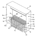
図1を参照すると、多重焦点X線管10が、セラミックフォーマ12及びフォーマの側部14と16との間に沿って延びるエミッタ素子18を備える。グリッドワイヤ20の形態の複数のグリッド素子がフォーマ12に支持され、その2つの側部14と16との間の隙間の上で、エミッタ素子18に対して垂直方向に、但しエミッタ素子18と平行な平面に延びる。集束ワイヤ22の形態の複数の集束素子が、グリッドワイヤ20を挟んでエミッタ素子とは反対側の別の平面で支持される。集束ワイヤ22は、グリッドワイヤ20と平行であり、グリッドワイヤと同じ間隔で互いに離間しており、各集束ワイヤ22は、グリッドワイヤ20のそれぞれと整列している。
Referring to FIG. 1, a
線源10は、エミッタユニット25のハウジング24に囲まれ、フォーマ12がハウジングのベース24a上に支持される。集束ワイヤ22は、2つの支持レール26a、26bに支持され、支持レール26a、26bは、エミッタ素子18と平行に延び、フォーマ12から離間しており、ハウジングのベース24a上に取り付けられている。支持レール26a、26bは、電気的に導通しているため、集束ワイヤ22の全てが互いに電気的に接続される。支持レール26aの一端は、ハウジングのベース24aから突出して集束ワイヤ22のための電気的接続部を提供するコネクタ28に接続される。グリッドワイヤ20はそれぞれ、フォーマの一方の側部16に沿って下方に延び、グリッドワイヤ20それぞれに個別の電気接続部を提供する各電気コネクタ30に接続される。
The
アノード32が、ハウジングの側壁24bと24cとの間に支持される。アノードは、エミッタ素子18と平行に延びる。したがって、グリッドワイヤ20及び集束ワイヤ22は、エミッタ素子18とアノード32との間に延びる。アノードに対する電気コネクタ34が、ハウジングの側壁24bから延びる。
An
エミッタ素子18は、フォーマの両端に支持され、ハウジングのさらなるコネクタ36、38を介して供給される電流により加熱される。
1つの位置から電子ビームを発生させるために、一対の隣接するグリッドワイヤ20を、素子18に対して正の引き出し電位に接続することができ、残りのグリッドワイヤは素子18に対して負の阻止電位に接続される。電子を引き出すために使用するワイヤ20の対を選択することにより、電子ビームの位置を選択することができる。X線は、電子が衝突する位置でアノード32から放射されるため、X線源の位置も、引き出しに使用するグリッドワイヤの対を選択することにより選択することができる。集束素子22は全て、グリッドワイヤ20に対して正の電位で維持されるため、グリッドワイヤの任意の対間で引き出された電子はまた、それに対応する集束素子22の対間を通過し、且つその対により集束される。
In order to generate an electron beam from one position, a pair of
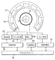
図2を参照すると、X線スキャナ50が従来の形状で設置され、中心スキャナ軸Xの回りに弧状に配置されるとともにスキャナ軸Xに向けてX線を放射するような向きのエミッタユニット25のアレイを備える。センサ52の輪が、スキャナ軸に向かって内方を向いて、エミッタの内側に配置される。センサ52及びエミッタユニット25は、軸Xに沿って互いにオフセットしているため、エミッタユニットから放射されるX線は、そのエミッタユニットから最も近いセンサを通って対象物を通過し、そのエミッタユニットから最も遠い複数のセンサにより検出される。各線源から放射されるX線を検出するセンサ52の数は、管25の各線源位置から放射されるX線のファン(fan:扇形)の幅に応じて変わる。スキャナは、図5の機能ブロックにより表される複数の機能を実行する制御システムにより制御される。システム制御ブロック54は、画像表示ユニット56、X線管制御ブロック58、及び画像再構成ブロック60を制御し、これらからデータを受け取る。X線管制御ブロック58は、エミッタユニット25それぞれの集束ワイヤ22の電位を制御する集束制御ブロック62と、エミッタユニット25それぞれの個々のグリッドワイヤ20の電位を制御するグリッド制御ブロック64と、エミッタブロックそれぞれのアノード32への電力及びエミッタ素子18への電力を供給する高電圧供給源68とを制御する。画像再構成ブロック60は、センサ制御ブロック70を制御してそこからデータを受け取り、センサ制御ブロック70はさらに、センサ52を制御してそこからデータを受け取る。
Referring to FIG. 2, an
動作時には、走査すべき対象物を軸Xに沿って通過させ、X線ビームをX線管25から対象物に通す。各走査サイクルにおいて、各管25の各線源位置が一度使用され、走査サイクルは、対象物が軸Xに沿って移動するごとに繰り返される。各線源位置がX線のファン(a fan of X rays:扇状のX線)を発生し、X線は、対象物を通過した後に複数のセンサ52により検出される。しかしながら、管及び管内の位置を使用する順序は、以下で説明するように制御される。
In operation, the object to be scanned is passed along the axis X and an X-ray beam is passed from the
管25の線源位置からのX線放射の順序は、X線管に対する熱負荷を最小にするように選択される。これは、各線源位置が前の線源位置及び次の線源位置に隣接しない、したがって前の線源位置及び次の線源位置から離間するように放射を順序付けることにより達成される。この順序付けは、各管25内の線源位置と、管自体とに適用される。したがって、各線源位置は、前の管及び次の管とは異なる管にある。実際には、最も好ましい熱負荷の分布は、線源位置が、各管から1つの位置を使用して全ての管を一巡し、次に各管内の異なる線源位置を使用して再び全ての管を一巡すれば達成される。この場合、全ての管の全ての線源位置が一度使用されるまで、周回が繰り返される。これにより、1回の走査サイクルが完了し、続いてこれを繰り返すことができる。
The order of X-ray radiation from the source position of the
各管内では、管内の熱負荷を分散させる順序で線源位置が取られる。これは、各線源位置とその管の次の線源位置との間の距離、及び各線源位置とその管の前の線源位置との間の距離の両方が最大になるように、線源位置を順序付けることにより達成される。したがって、まず、1つの管あたりの線源位置の数により可能である場合、管の各線源位置は、その管の次の線源位置及び前の線源位置と隣接してはならない。次に、線源位置の数に応じて、熱負荷をできる限り分布させるように順序付けが選択される。 Within each tube, the source positions are taken in an order that distributes the thermal load within the tube. This is because the source is such that both the distance between each source location and the next source location of the tube and the distance between each source location and the previous source location of the tube are maximized. This is achieved by ordering the positions. Thus, first, where possible by the number of source positions per tube, each tube source position must not be adjacent to the next and previous source positions of that tube. Next, depending on the number of source positions, ordering is selected to distribute the heat load as much as possible.
例えば、図3に示す本発明の第2の実施形態の場合、1、2、3、4、及び5と位置決めされた順に番号付けされた5つのX線管60、61、62、63、64があり、これらそれぞれが、同様に管60に沿って順に1、2、3、4、及び5と番号付けされた5つの線源位置70、71、72、73、74からX線を発生することができる。この場合、各管内の線源位置の最も好ましい順序は、1、3、5、2、4である。連続した放射間の角度分離を最大にするための管の順序付けにも、同じシーケンスが使用される。これにより、以下のような放射順序ができ、ここで、線源位置は、対象物75の周りを管60の左側端の列の左端から始めて、管64の右側端の列の右端まで順に数えて番号付けされる。
For example, in the case of the second embodiment of the present invention shown in FIG. 3, five

例えば、対象物75を囲む形状の単一の管の25個の線源位置とともに、同じ順序付けを使用することもできる。
For example, the same ordering can be used with 25 source positions of a single tube shaped to surround
5つ未満の線源位置を有するX線管の場合、後続の放射において隣接する位置を使用しないわけにはいかないことが理解されるであろう。しかしながら、5つ以上のX線源位置を有する管の場合、これを避けることができる。 It will be appreciated that for X-ray tubes having less than 5 source positions, it is not without failure to use adjacent positions in subsequent radiation. However, this can be avoided in the case of a tube having more than 5 x-ray source positions.
図4を参照すると、本発明の第3の実施形態では、複数のX線源80が軸Xの周りで離間しており、第1の実施形態のように、複数のセンサ82が線源80から軸方向にオフセットしている。線源の1つである80aがX線ビーム84を放射すると、これが発散し、対象物86を通過し、複数のセンサ82に到達する。線源それぞれからのX線を検出するセンサ82の数は、任意所与のシステムの既知の量であるX線ビームの幅に応じて変わり、半角に関して定量化することができる。半角は、ビームの中心とビームの縁との間の角度である。
Referring to FIG. 4, in the third embodiment of the present invention, a plurality of X-ray sources 80 are spaced around the axis X, and a plurality of
線源位置80それぞれからのX線を検出するために必要なセンサ82が既知である場合、同時に放射できる線源位置を選択することができるが、これは線源位置が共通の検出器を必要としないことを条件とする。例えば、24個の線源位置80及び24個のセンサ82があり、各線源位置が5個のセンサを必要とする場合、対象物の周りに90°の間隔で離間している4つのセンサ80a、80b、80c、80dを同時に使用することができる。
If the
実際には、線源位置及びセンサの数は、これよりも多い可能性が高い。ナイキストサンプリング定理を満たすためには、線源位置の数Nφを、対象物の線形寸法Nsdをカバーするのに必要な幅dを有するセンサの数Nsと一致させることが必要である。これにより、結果は以下のようになる:Nφ=πNs/2。 In practice, the source position and the number of sensors are likely to be higher. In order to satisfy the Nyquist sampling theorem, it is necessary to match the number N φ of source positions with the number N s of sensors having the width d necessary to cover the linear dimension N s d of the object. . This results in the following: N φ = πN s / 2.
例えば、Ns=64である場合の画像は、ナイキストサンプリング基準を満たすためには、Nφ=100のサンプリング点を必要とする。 For example, an image with N s = 64 requires N φ = 100 sampling points to meet the Nyquist sampling criterion.
放射位置の順序付けは、任意所与の数の放射位置に関して多くの方法で変えることができ、最適な順序付けは、放射位置の数及びX線管の数に応じて変えることもできることが、理解されるであろう。 It is understood that the ordering of the radiation positions can be varied in many ways for any given number of radiation positions, and the optimal ordering can be varied depending on the number of radiation positions and the number of x-ray tubes. It will be.
10・・・X線管、 12・・・セラミックフォーマ、 14、16・・・側部、 18・・・エミッタ素子、 20・・・グリッドワイヤ、 22・・・集束ワイヤ、 24・・・ハウジング、 25・・・エミッタユニット、 26a、26b・・・支持レール、 28・・・コネクタ、 30・・・電気コネクタ、 32・・・アノード、 34・・・電気コネクタ、 36・・・コネクタ、 50・・・線スキャナ、 52・・・センサ、 54・・・システム制御ブロック、 56・・・画像表示ユニット、 58・・・線管制御ブロック、 60・・・画像再構成ブロック、 62・・・集束制御ブロック、 64・・・グリッド制御ブロック、 68・・・高電圧供給源、 70・・・センサ制御ブロック、 75・・・対象物、 80a〜80d・・・センサ、 80・・・線源、 82・・・センサ、 84・・・線ビーム、 86・・・対象物。
DESCRIPTION OF
Claims (8)
該線源位置から放射されて該対象物の位置を通過するX線を検出するように、該対象物位置の周りで離間して配置される複数のX線センサと、
各放射期間中に、該アクティブな線源位置が前の放射期間中の該アクティブな線源位置を提供するX線管とは異なるX線管にあるように、該線源位置がアクティブになる順序を制御する制御手段と、を備えることを特徴とするX線画像形成装置。A plurality of x-ray tubes each providing a plurality of source positions spaced about the object position and spaced from each other by a source spacing;
A plurality of X-ray sensors spaced apart around the object position to detect X-rays emitted from the source position and passing through the object position;
During each emission period, the source position becomes active such that the active source position is in a different X-ray tube than the X-ray tube providing the active source position during the previous emission period X-ray imaging apparatus comprising: the that control means to control the order, the.
Applications Claiming Priority (3)
| Application Number | Priority Date | Filing Date | Title |
|---|---|---|---|
| GB0309387.9 | 2003-04-25 | ||
| GBGB0309387.9A GB0309387D0 (en) | 2003-04-25 | 2003-04-25 | X-Ray scanning |
| PCT/GB2004/001729 WO2004097386A1 (en) | 2003-04-25 | 2004-04-23 | Control means for heat load in x-ray scanning apparatus |
Publications (3)
| Publication Number | Publication Date |
|---|---|
| JP2006524809A JP2006524809A (en) | 2006-11-02 |
| JP2006524809A5 JP2006524809A5 (en) | 2007-06-14 |
| JP4861818B2 true JP4861818B2 (en) | 2012-01-25 |
Family
ID=9957207
Family Applications (1)
| Application Number | Title | Priority Date | Filing Date |
|---|---|---|---|
| JP2006506163A Expired - Fee Related JP4861818B2 (en) | 2003-04-25 | 2004-04-23 | Control means for controlling thermal load of X-ray scanning apparatus |
Country Status (9)
| Country | Link |
|---|---|
| US (2) | US7564939B2 (en) |
| EP (1) | EP1618368B1 (en) |
| JP (1) | JP4861818B2 (en) |
| CN (1) | CN1781018B (en) |
| AT (1) | ATE443253T1 (en) |
| DE (1) | DE602004023188D1 (en) |
| ES (1) | ES2333331T3 (en) |
| GB (2) | GB0309387D0 (en) |
| WO (1) | WO2004097386A1 (en) |
Families Citing this family (47)
| Publication number | Priority date | Publication date | Assignee | Title |
|---|---|---|---|---|
| US8275091B2 (en) | 2002-07-23 | 2012-09-25 | Rapiscan Systems, Inc. | Compact mobile cargo scanning system |
| US7963695B2 (en) | 2002-07-23 | 2011-06-21 | Rapiscan Systems, Inc. | Rotatable boom cargo scanning system |
| US8804899B2 (en) | 2003-04-25 | 2014-08-12 | Rapiscan Systems, Inc. | Imaging, data acquisition, data transmission, and data distribution methods and systems for high data rate tomographic X-ray scanners |
| US9113839B2 (en) | 2003-04-25 | 2015-08-25 | Rapiscon Systems, Inc. | X-ray inspection system and method |
| GB0525593D0 (en) * | 2005-12-16 | 2006-01-25 | Cxr Ltd | X-ray tomography inspection systems |
| US8243876B2 (en) | 2003-04-25 | 2012-08-14 | Rapiscan Systems, Inc. | X-ray scanners |
| US8094784B2 (en) | 2003-04-25 | 2012-01-10 | Rapiscan Systems, Inc. | X-ray sources |
| US8223919B2 (en) | 2003-04-25 | 2012-07-17 | Rapiscan Systems, Inc. | X-ray tomographic inspection systems for the identification of specific target items |
| US9208988B2 (en) | 2005-10-25 | 2015-12-08 | Rapiscan Systems, Inc. | Graphite backscattered electron shield for use in an X-ray tube |
| GB0309371D0 (en) | 2003-04-25 | 2003-06-04 | Cxr Ltd | X-Ray tubes |
| US7949101B2 (en) | 2005-12-16 | 2011-05-24 | Rapiscan Systems, Inc. | X-ray scanners and X-ray sources therefor |
| US10483077B2 (en) | 2003-04-25 | 2019-11-19 | Rapiscan Systems, Inc. | X-ray sources having reduced electron scattering |
| US8837669B2 (en) | 2003-04-25 | 2014-09-16 | Rapiscan Systems, Inc. | X-ray scanning system |
| GB0812864D0 (en) | 2008-07-15 | 2008-08-20 | Cxr Ltd | Coolign anode |
| US8451974B2 (en) | 2003-04-25 | 2013-05-28 | Rapiscan Systems, Inc. | X-ray tomographic inspection system for the identification of specific target items |
| US6928141B2 (en) | 2003-06-20 | 2005-08-09 | Rapiscan, Inc. | Relocatable X-ray imaging system and method for inspecting commercial vehicles and cargo containers |
| US7471764B2 (en) | 2005-04-15 | 2008-12-30 | Rapiscan Security Products, Inc. | X-ray imaging system having improved weather resistance |
| US9046465B2 (en) | 2011-02-24 | 2015-06-02 | Rapiscan Systems, Inc. | Optimization of the source firing pattern for X-ray scanning systems |
| US7706499B2 (en) * | 2006-08-30 | 2010-04-27 | General Electric Company | Acquisition and reconstruction of projection data using a stationary CT geometry |
| DE102007012362A1 (en) * | 2007-03-14 | 2008-09-18 | Siemens Ag | X-ray machine |
| DE102008004473A1 (en) * | 2008-01-15 | 2009-07-23 | Siemens Aktiengesellschaft | Method and device for generating a tomosynthetic 3D X-ray image |
| GB0803641D0 (en) | 2008-02-28 | 2008-04-02 | Rapiscan Security Products Inc | Scanning systems |
| GB0803644D0 (en) | 2008-02-28 | 2008-04-02 | Rapiscan Security Products Inc | Scanning systems |
| GB0809110D0 (en) | 2008-05-20 | 2008-06-25 | Rapiscan Security Products Inc | Gantry scanner systems |
| US7809101B2 (en) | 2008-06-06 | 2010-10-05 | General Electric Company | Modular multispot X-ray source and method of making same |
| GB0816823D0 (en) | 2008-09-13 | 2008-10-22 | Cxr Ltd | X-ray tubes |
| GB0901338D0 (en) | 2009-01-28 | 2009-03-11 | Cxr Ltd | X-Ray tube electron sources |
| US7756249B1 (en) * | 2009-02-19 | 2010-07-13 | Morpho Detection, Inc. | Compact multi-focus x-ray source, x-ray diffraction imaging system, and method for fabricating compact multi-focus x-ray source |
| JP2012528397A (en) | 2009-05-26 | 2012-11-12 | ラピスカン システムズ、インコーポレイテッド | X-ray tomography inspection system for identification of specific target articles |
| GB2486057B (en) | 2009-05-26 | 2013-12-25 | Rapiscan Systems Inc | X-ray tomographic inspection system for the idendification of specific target items |
| US8713131B2 (en) | 2010-02-23 | 2014-04-29 | RHPiscan Systems, Inc. | Simultaneous image distribution and archiving |
| US9218933B2 (en) | 2011-06-09 | 2015-12-22 | Rapidscan Systems, Inc. | Low-dose radiographic imaging system |
| WO2013008685A1 (en) * | 2011-07-12 | 2013-01-17 | 富士フイルム株式会社 | Radiation output device, radiography system, and radiography method |
| US8948338B2 (en) * | 2011-11-03 | 2015-02-03 | Medtronic Navigation, Inc. | Dynamically scanned X-ray detector panel |
| CN103308535B (en) * | 2012-03-09 | 2016-04-13 | 同方威视技术股份有限公司 | For equipment and the method for ray scanning imaging |
| IN2014DN10327A (en) * | 2012-06-05 | 2015-08-07 | Rapiscan Systems Inc | |
| US9791590B2 (en) | 2013-01-31 | 2017-10-17 | Rapiscan Systems, Inc. | Portable security inspection system |
| CN104470178A (en) | 2013-09-18 | 2015-03-25 | 清华大学 | X-ray device and CT device with same |
| CA3059061A1 (en) | 2017-04-17 | 2018-10-25 | Rapiscan Systems, Inc. | X-ray tomography inspection systems and methods |
| CN109216137B (en) * | 2017-06-30 | 2024-04-05 | 同方威视技术股份有限公司 | Distributed X-ray source and control method thereof |
| JP2020532089A (en) | 2017-09-02 | 2020-11-05 | チェッテーン ゲゼルシャフト ミット ベシュレンクテル ハフツング | Control devices for X-ray tubes and how to operate the X-ray tubes |
| US10585206B2 (en) | 2017-09-06 | 2020-03-10 | Rapiscan Systems, Inc. | Method and system for a multi-view scanner |
| JPWO2019151250A1 (en) * | 2018-01-31 | 2021-02-18 | ナノックス イメージング リミテッド | X-ray equipment and tomosynthesis image composition method |
| JP7184584B2 (en) * | 2018-09-27 | 2022-12-06 | 富士フイルム株式会社 | radiography equipment |
| US11594001B2 (en) | 2020-01-20 | 2023-02-28 | Rapiscan Systems, Inc. | Methods and systems for generating three-dimensional images that enable improved visualization and interaction with objects in the three-dimensional images |
| US11551903B2 (en) | 2020-06-25 | 2023-01-10 | American Science And Engineering, Inc. | Devices and methods for dissipating heat from an anode of an x-ray tube assembly |
| EP3933881A1 (en) | 2020-06-30 | 2022-01-05 | VEC Imaging GmbH & Co. KG | X-ray source with multiple grids |
Citations (7)
| Publication number | Priority date | Publication date | Assignee | Title |
|---|---|---|---|---|
| JPS5155286A (en) * | 1974-09-06 | 1976-05-14 | Philips Nv | |
| JPS5250186A (en) * | 1975-10-18 | 1977-04-21 | Emi Ltd | Xxray tube device |
| JPS5546408A (en) * | 1978-09-29 | 1980-04-01 | Toshiba Corp | X-ray device |
| JPH0793525A (en) * | 1993-02-13 | 1995-04-07 | Philips Electron Nv | Method and apparatus for generation of fault image |
| JPH10272128A (en) * | 1997-03-31 | 1998-10-13 | Futec Inc | Method and apparatus for direct tomographic photographing |
| JP2001204723A (en) * | 1999-12-30 | 2001-07-31 | Ge Medical Systems Global Technology Co Llc | Weighting of partial scanning for multi-slice ct image pickup having optional pitch |
| JP2002343291A (en) * | 2000-12-29 | 2002-11-29 | Ge Medical Systems Global Technology Co Llc | Solid-state ct system and method |
Family Cites Families (76)
| Publication number | Priority date | Publication date | Assignee | Title |
|---|---|---|---|---|
| US32961A (en) * | 1861-07-30 | Animal-trap | ||
| US2952790A (en) | 1957-07-15 | 1960-09-13 | Raytheon Co | X-ray tubes |
| US3239706A (en) | 1961-04-17 | 1966-03-08 | High Voltage Engineering Corp | X-ray target |
| US3768645A (en) | 1971-02-22 | 1973-10-30 | Sunkist Growers Inc | Method and means for automatically detecting and sorting produce according to internal damage |
| GB1497396A (en) | 1974-03-23 | 1978-01-12 | Emi Ltd | Radiography |
| USRE32961E (en) | 1974-09-06 | 1989-06-20 | U.S. Philips Corporation | Device for measuring local radiation absorption in a body |
| GB1526041A (en) | 1975-08-29 | 1978-09-27 | Emi Ltd | Sources of x-radiation |
| DE2647167A1 (en) | 1976-10-19 | 1978-04-20 | Siemens Ag | PROCESS FOR THE PRODUCTION OF LAYERS WITH X-RAYS OR SIMILAR PENETRATING RAYS |
| DE2705640A1 (en) | 1977-02-10 | 1978-08-17 | Siemens Ag | COMPUTER SYSTEM FOR THE PICTURE STRUCTURE OF A BODY SECTION AND PROCESS FOR OPERATING THE COMPUTER SYSTEM |
| US4105922A (en) | 1977-04-11 | 1978-08-08 | General Electric Company | CT number identifier in a computed tomography system |
| DE2729353A1 (en) | 1977-06-29 | 1979-01-11 | Siemens Ag | X=ray tube with migrating focal spot for tomography appts. - has shaped anode, several control grids at common potential and separately switched cathode |
| DE2807735B2 (en) | 1978-02-23 | 1979-12-20 | Philips Patentverwaltung Gmbh, 2000 Hamburg | X-ray tube with a tubular piston made of metal |
| US4228353A (en) | 1978-05-02 | 1980-10-14 | Johnson Steven A | Multiple-phase flowmeter and materials analysis apparatus and method |
| US4266425A (en) | 1979-11-09 | 1981-05-12 | Zikonix Corporation | Method for continuously determining the composition and mass flow of butter and similar substances from a manufacturing process |
| US4352021A (en) | 1980-01-07 | 1982-09-28 | The Regents Of The University Of California | X-Ray transmission scanning system and method and electron beam X-ray scan tube for use therewith |
| GB2089109B (en) | 1980-12-03 | 1985-05-15 | Machlett Lab Inc | X-rays targets and tubes |
| DE3107949A1 (en) | 1981-03-02 | 1982-09-16 | Siemens AG, 1000 Berlin und 8000 München | X-RAY TUBES |
| FR2534066B1 (en) | 1982-10-05 | 1989-09-08 | Thomson Csf | X-RAY TUBE PRODUCING A HIGH EFFICIENCY BEAM, ESPECIALLY BRUSH-SHAPED |
| US4672649A (en) | 1984-05-29 | 1987-06-09 | Imatron, Inc. | Three dimensional scanned projection radiography using high speed computed tomographic scanning system |
| GB8521287D0 (en) | 1985-08-27 | 1985-10-02 | Frith B | Flow measurement & imaging |
| US4799247A (en) | 1986-06-20 | 1989-01-17 | American Science And Engineering, Inc. | X-ray imaging particularly adapted for low Z materials |
| JPS6321040A (en) | 1986-07-16 | 1988-01-28 | 工業技術院長 | Ultrahigh speed x-ray ct scanner |
| JPS63109653A (en) | 1986-10-27 | 1988-05-14 | Sharp Corp | Information registering and retrieving device |
| GB2212903B (en) | 1987-11-24 | 1991-11-06 | Rolls Royce Plc | Measuring two phase flow in pipes. |
| US4887604A (en) | 1988-05-16 | 1989-12-19 | Science Research Laboratory, Inc. | Apparatus for performing dual energy medical imaging |
| EP0432568A3 (en) | 1989-12-11 | 1991-08-28 | General Electric Company | X ray tube anode and tube having same |
| DE4100297A1 (en) | 1991-01-08 | 1992-07-09 | Philips Patentverwaltung | X-RAY TUBES |
| DE4103588C1 (en) | 1991-02-06 | 1992-05-27 | Siemens Ag, 8000 Muenchen, De | |
| US5272627A (en) | 1991-03-27 | 1993-12-21 | Gulton Industries, Inc. | Data converter for CT data acquisition system |
| EP0531993B1 (en) | 1991-09-12 | 1998-01-07 | Kabushiki Kaisha Toshiba | X-ray computerized tomographic imaging method and imaging system capable of forming scanogram data from helically scanned data |
| US5367552A (en) | 1991-10-03 | 1994-11-22 | In Vision Technologies, Inc. | Automatic concealed object detection system having a pre-scan stage |
| US5966422A (en) | 1992-07-20 | 1999-10-12 | Picker Medical Systems, Ltd. | Multiple source CT scanner |
| DE4228559A1 (en) | 1992-08-27 | 1994-03-03 | Dagang Tan | X-ray tube with a transmission anode |
| US5511104A (en) | 1994-03-11 | 1996-04-23 | Siemens Aktiengesellschaft | X-ray tube |
| US5467377A (en) * | 1994-04-15 | 1995-11-14 | Dawson; Ralph L. | Computed tomographic scanner |
| SE9401300L (en) | 1994-04-18 | 1995-10-19 | Bgc Dev Ab | Rotating cylinder collimator for collimation of ionizing, electromagnetic radiation |
| DE4436688A1 (en) | 1994-10-13 | 1996-04-25 | Siemens Ag | Spiral computer tomograph for human body investigation |
| AUPN226295A0 (en) | 1995-04-07 | 1995-05-04 | Technological Resources Pty Limited | A method and an apparatus for analysing a material |
| US6018562A (en) | 1995-11-13 | 2000-01-25 | The United States Of America As Represented By The Secretary Of The Army | Apparatus and method for automatic recognition of concealed objects using multiple energy computed tomography |
| DE19542438C1 (en) | 1995-11-14 | 1996-11-28 | Siemens Ag | X=ray tube with vacuum housing having cathode and anode |
| US5633907A (en) | 1996-03-21 | 1997-05-27 | General Electric Company | X-ray tube electron beam formation and focusing |
| DE19618749A1 (en) | 1996-05-09 | 1997-11-13 | Siemens Ag | X=ray computer tomograph for human body investigation |
| US5974111A (en) | 1996-09-24 | 1999-10-26 | Vivid Technologies, Inc. | Identifying explosives or other contraband by employing transmitted or scattered X-rays |
| US5859891A (en) | 1997-03-07 | 1999-01-12 | Hibbard; Lyn | Autosegmentation/autocontouring system and method for use with three-dimensional radiation therapy treatment planning |
| US6149592A (en) | 1997-11-26 | 2000-11-21 | Picker International, Inc. | Integrated fluoroscopic projection image data, volumetric image data, and surgical device position data |
| US6005918A (en) | 1997-12-19 | 1999-12-21 | Picker International, Inc. | X-ray tube window heat shield |
| US5987097A (en) | 1997-12-23 | 1999-11-16 | General Electric Company | X-ray tube having reduced window heating |
| US6218943B1 (en) | 1998-03-27 | 2001-04-17 | Vivid Technologies, Inc. | Contraband detection and article reclaim system |
| US6236709B1 (en) | 1998-05-04 | 2001-05-22 | Ensco, Inc. | Continuous high speed tomographic imaging system and method |
| US6097786A (en) | 1998-05-18 | 2000-08-01 | Schlumberger Technology Corporation | Method and apparatus for measuring multiphase flows |
| US6183139B1 (en) | 1998-10-06 | 2001-02-06 | Cardiac Mariners, Inc. | X-ray scanning method and apparatus |
| US6181765B1 (en) | 1998-12-10 | 2001-01-30 | General Electric Company | X-ray tube assembly |
| US6546072B1 (en) | 1999-07-30 | 2003-04-08 | American Science And Engineering, Inc. | Transmission enhanced scatter imaging |
| US6269142B1 (en) | 1999-08-11 | 2001-07-31 | Steven W. Smith | Interrupted-fan-beam imaging |
| US6528787B2 (en) | 1999-11-30 | 2003-03-04 | Jeol Ltd. | Scanning electron microscope |
| JP2001176408A (en) | 1999-12-15 | 2001-06-29 | New Japan Radio Co Ltd | Electron tube |
| WO2001094984A2 (en) | 2000-06-07 | 2001-12-13 | American Science And Engineering, Inc. | X-ray scatter and transmission system with coded beams |
| US6876724B2 (en) | 2000-10-06 | 2005-04-05 | The University Of North Carolina - Chapel Hill | Large-area individually addressable multi-beam x-ray system and method of forming same |
| US6735271B1 (en) | 2000-11-28 | 2004-05-11 | Ge Medical Systems Global Technology Company Llc | Electron beam computed tomographic scanner system with helical or tilted target, collimator, and detector components to eliminate cone beam error and to scan continuously moving objects |
| JPWO2002067779A1 (en) | 2001-02-28 | 2004-06-24 | 三菱重工業株式会社 | Multi-source X-ray CT system |
| US6324249B1 (en) | 2001-03-21 | 2001-11-27 | Agilent Technologies, Inc. | Electronic planar laminography system and method |
| US7139406B2 (en) | 2001-04-03 | 2006-11-21 | L-3 Communications Security And Detection Systems | Remote baggage screening system, software and method |
| GB0115615D0 (en) | 2001-06-27 | 2001-08-15 | Univ Coventry | Image segmentation |
| US6636623B2 (en) | 2001-08-10 | 2003-10-21 | Visiongate, Inc. | Optical projection imaging system and method for automatically detecting cells with molecular marker compartmentalization associated with malignancy and disease |
| CN1344534A (en) * | 2001-11-09 | 2002-04-17 | 曹文田 | Spiral computerized tomography instrument |
| WO2003051201A2 (en) | 2001-12-14 | 2003-06-26 | Wisconsin Alumni Research Foundation | Virtual spherical anode computed tomography |
| AU2003209587A1 (en) | 2002-03-23 | 2003-10-08 | Philips Intellectual Property And Standards Gmbh | Method for interactive segmentation of a structure contained in an object |
| US6754300B2 (en) | 2002-06-20 | 2004-06-22 | Ge Medical Systems Global Technology Company, Llc | Methods and apparatus for operating a radiation source |
| JP2004079128A (en) | 2002-08-22 | 2004-03-11 | Matsushita Electric Ind Co Ltd | Optical disk recorder |
| EP1549934B1 (en) | 2002-10-02 | 2011-01-19 | Reveal Imaging Technologies, Inc. | Folded array ct baggage scanner |
| US6922460B2 (en) | 2003-06-11 | 2005-07-26 | Quantum Magnetics, Inc. | Explosives detection system using computed tomography (CT) and quadrupole resonance (QR) sensors |
| US7492855B2 (en) | 2003-08-07 | 2009-02-17 | General Electric Company | System and method for detecting an object |
| JP3909048B2 (en) | 2003-09-05 | 2007-04-25 | ジーイー・メディカル・システムズ・グローバル・テクノロジー・カンパニー・エルエルシー | X-ray CT apparatus and X-ray tube |
| US7099435B2 (en) | 2003-11-15 | 2006-08-29 | Agilent Technologies, Inc | Highly constrained tomography for automated inspection of area arrays |
| US7280631B2 (en) | 2003-11-26 | 2007-10-09 | General Electric Company | Stationary computed tomography system and method |
| US7233644B1 (en) * | 2004-11-30 | 2007-06-19 | Ge Homeland Protection, Inc. | Computed tomographic scanner using rastered x-ray tubes |
-
2003
- 2003-04-25 GB GBGB0309387.9A patent/GB0309387D0/en not_active Ceased
-
2004
- 2004-04-23 WO PCT/GB2004/001729 patent/WO2004097386A1/en active Application Filing
- 2004-04-23 EP EP04729148A patent/EP1618368B1/en not_active Expired - Fee Related
- 2004-04-23 AT AT04729148T patent/ATE443253T1/en not_active IP Right Cessation
- 2004-04-23 US US10/554,656 patent/US7564939B2/en not_active Expired - Lifetime
- 2004-04-23 DE DE602004023188T patent/DE602004023188D1/en not_active Expired - Lifetime
- 2004-04-23 JP JP2006506163A patent/JP4861818B2/en not_active Expired - Fee Related
- 2004-04-23 CN CN2004800112124A patent/CN1781018B/en not_active Expired - Fee Related
- 2004-04-23 GB GB0520903A patent/GB2416654B/en not_active Expired - Lifetime
- 2004-04-23 ES ES04729148T patent/ES2333331T3/en not_active Expired - Lifetime
-
2009
- 2009-06-16 US US12/485,897 patent/US20090316855A1/en not_active Abandoned
Patent Citations (7)
| Publication number | Priority date | Publication date | Assignee | Title |
|---|---|---|---|---|
| JPS5155286A (en) * | 1974-09-06 | 1976-05-14 | Philips Nv | |
| JPS5250186A (en) * | 1975-10-18 | 1977-04-21 | Emi Ltd | Xxray tube device |
| JPS5546408A (en) * | 1978-09-29 | 1980-04-01 | Toshiba Corp | X-ray device |
| JPH0793525A (en) * | 1993-02-13 | 1995-04-07 | Philips Electron Nv | Method and apparatus for generation of fault image |
| JPH10272128A (en) * | 1997-03-31 | 1998-10-13 | Futec Inc | Method and apparatus for direct tomographic photographing |
| JP2001204723A (en) * | 1999-12-30 | 2001-07-31 | Ge Medical Systems Global Technology Co Llc | Weighting of partial scanning for multi-slice ct image pickup having optional pitch |
| JP2002343291A (en) * | 2000-12-29 | 2002-11-29 | Ge Medical Systems Global Technology Co Llc | Solid-state ct system and method |
Also Published As
| Publication number | Publication date |
|---|---|
| GB2416654A (en) | 2006-02-01 |
| GB0520903D0 (en) | 2005-11-23 |
| US20070172023A1 (en) | 2007-07-26 |
| WO2004097386A1 (en) | 2004-11-11 |
| WO2004097386A8 (en) | 2005-01-20 |
| EP1618368A1 (en) | 2006-01-25 |
| GB0309387D0 (en) | 2003-06-04 |
| EP1618368B1 (en) | 2009-09-16 |
| US7564939B2 (en) | 2009-07-21 |
| JP2006524809A (en) | 2006-11-02 |
| ATE443253T1 (en) | 2009-10-15 |
| GB2416654B (en) | 2006-12-13 |
| ES2333331T3 (en) | 2010-02-19 |
| DE602004023188D1 (en) | 2009-10-29 |
| CN1781018B (en) | 2011-06-08 |
| US20090316855A1 (en) | 2009-12-24 |
| CN1781018A (en) | 2006-05-31 |
Similar Documents
| Publication | Publication Date | Title |
|---|---|---|
| JP4861818B2 (en) | Control means for controlling thermal load of X-ray scanning apparatus | |
| US20210137470A1 (en) | Optimization of the Source Firing Pattern for X-Ray Scanning Systems | |
| EP1211917B1 (en) | Imaging apparatus and method | |
| JP5797727B2 (en) | Device and method for generating distributed X-rays | |
| US20100074392A1 (en) | X-ray tube with multiple electron sources and common electron deflection unit | |
| JP2012527079A (en) | X-ray source and x-ray generation method | |
| CN101512379B (en) | Acquisition and reconstruction of projection data using a stationary ct geometry | |
| JP2005245559A (en) | X-ray ct apparatus and x-ray device | |
| KR101939434B1 (en) | Optimization of the source firing pattern for x-ray scanning systems | |
| JP4585195B2 (en) | X-ray CT system | |
| CN113133772A (en) | PET-CT system and scanning method | |
| JP2006015050A (en) | X-ray ct apparatus | |
| US11282668B2 (en) | X-ray tube and a controller thereof | |
| JPS59149642A (en) | X-ray tube with adjustable focus | |
| JP7403009B2 (en) | Deflection electrode assembly, X-ray source and X-ray imaging system | |
| JP5823178B2 (en) | X-ray CT system | |
| JP2010146992A (en) | Scanning type x-ray tube | |
| KR20170060453A (en) | X-ray imaging apparatus having multi x-ray sources and detectors | |
| CN107847208B (en) | X-ray apparatus for inverse computed tomography | |
| US9601300B2 (en) | Cathode element for a microfocus x-ray tube | |
| CN116153746A (en) | Cathode unitized X-ray source, static CT imaging system and image enhancement method | |
| JP2014226475A (en) | X-ray computed tomography apparatus | |
| JP2019063429A (en) | Medical image diagnostic system | |
| JP2010148920A (en) | X-ray ct system | |
| JP2019195481A (en) | X-ray CT apparatus and medical image processing apparatus |
Legal Events
| Date | Code | Title | Description |
|---|---|---|---|
| A521 | Request for written amendment filed |
Free format text: JAPANESE INTERMEDIATE CODE: A523 Effective date: 20070412 |
|
| A621 | Written request for application examination |
Free format text: JAPANESE INTERMEDIATE CODE: A621 Effective date: 20070412 |
|
| A131 | Notification of reasons for refusal |
Free format text: JAPANESE INTERMEDIATE CODE: A131 Effective date: 20100126 |
|
| A601 | Written request for extension of time |
Free format text: JAPANESE INTERMEDIATE CODE: A601 Effective date: 20100420 |
|
| A602 | Written permission of extension of time |
Free format text: JAPANESE INTERMEDIATE CODE: A602 Effective date: 20100427 |
|
| A521 | Request for written amendment filed |
Free format text: JAPANESE INTERMEDIATE CODE: A523 Effective date: 20100512 |
|
| A131 | Notification of reasons for refusal |
Free format text: JAPANESE INTERMEDIATE CODE: A131 Effective date: 20110203 |
|
| A601 | Written request for extension of time |
Free format text: JAPANESE INTERMEDIATE CODE: A601 Effective date: 20110428 |
|
| A602 | Written permission of extension of time |
Free format text: JAPANESE INTERMEDIATE CODE: A602 Effective date: 20110511 |
|
| A521 | Request for written amendment filed |
Free format text: JAPANESE INTERMEDIATE CODE: A523 Effective date: 20110531 |
|
| A131 | Notification of reasons for refusal |
Free format text: JAPANESE INTERMEDIATE CODE: A131 Effective date: 20110630 |
|
| A521 | Request for written amendment filed |
Free format text: JAPANESE INTERMEDIATE CODE: A523 Effective date: 20110916 |
|
| TRDD | Decision of grant or rejection written | ||
| A01 | Written decision to grant a patent or to grant a registration (utility model) |
Free format text: JAPANESE INTERMEDIATE CODE: A01 Effective date: 20111013 |
|
| A01 | Written decision to grant a patent or to grant a registration (utility model) |
Free format text: JAPANESE INTERMEDIATE CODE: A01 |
|
| A61 | First payment of annual fees (during grant procedure) |
Free format text: JAPANESE INTERMEDIATE CODE: A61 Effective date: 20111107 |
|
| R150 | Certificate of patent or registration of utility model |
Ref document number: 4861818 Country of ref document: JP Free format text: JAPANESE INTERMEDIATE CODE: R150 Free format text: JAPANESE INTERMEDIATE CODE: R150 |
|
| FPAY | Renewal fee payment (event date is renewal date of database) |
Free format text: PAYMENT UNTIL: 20141111 Year of fee payment: 3 |
|
| R250 | Receipt of annual fees |
Free format text: JAPANESE INTERMEDIATE CODE: R250 |
|
| R250 | Receipt of annual fees |
Free format text: JAPANESE INTERMEDIATE CODE: R250 |
|
| R250 | Receipt of annual fees |
Free format text: JAPANESE INTERMEDIATE CODE: R250 |
|
| R250 | Receipt of annual fees |
Free format text: JAPANESE INTERMEDIATE CODE: R250 |
|
| R250 | Receipt of annual fees |
Free format text: JAPANESE INTERMEDIATE CODE: R250 |
|
| R250 | Receipt of annual fees |
Free format text: JAPANESE INTERMEDIATE CODE: R250 |
|
| LAPS | Cancellation because of no payment of annual fees |