JP4860627B2 - Vehicle steering device - Google Patents
Vehicle steering device Download PDFInfo
- Publication number
- JP4860627B2 JP4860627B2 JP2007537391A JP2007537391A JP4860627B2 JP 4860627 B2 JP4860627 B2 JP 4860627B2 JP 2007537391 A JP2007537391 A JP 2007537391A JP 2007537391 A JP2007537391 A JP 2007537391A JP 4860627 B2 JP4860627 B2 JP 4860627B2
- Authority
- JP
- Japan
- Prior art keywords
- steering
- column
- connecting portion
- vehicle
- vehicle steering
- Prior art date
- Legal status (The legal status is an assumption and is not a legal conclusion. Google has not performed a legal analysis and makes no representation as to the accuracy of the status listed.)
- Expired - Fee Related
Links
Images


Classifications
-
- B—PERFORMING OPERATIONS; TRANSPORTING
- B60—VEHICLES IN GENERAL
- B60F—VEHICLES FOR USE BOTH ON RAIL AND ON ROAD; AMPHIBIOUS OR LIKE VEHICLES; CONVERTIBLE VEHICLES
- B60F3/00—Amphibious vehicles, i.e. vehicles capable of travelling both on land and on water; Land vehicles capable of travelling under water
- B60F3/0007—Arrangement of propulsion or steering means on amphibious vehicles
-
- B—PERFORMING OPERATIONS; TRANSPORTING
- B60—VEHICLES IN GENERAL
- B60F—VEHICLES FOR USE BOTH ON RAIL AND ON ROAD; AMPHIBIOUS OR LIKE VEHICLES; CONVERTIBLE VEHICLES
- B60F2301/00—Retractable wheels
- B60F2301/04—Retractable wheels pivotally
-
- B—PERFORMING OPERATIONS; TRANSPORTING
- B60—VEHICLES IN GENERAL
- B60G—VEHICLE SUSPENSION ARRANGEMENTS
- B60G2204/00—Indexing codes related to suspensions per se or to auxiliary parts
- B60G2204/10—Mounting of suspension elements
- B60G2204/12—Mounting of springs or dampers
- B60G2204/13—Mounting of springs or dampers with the spring, i.e. coil spring, or damper horizontally mounted
Abstract
Description
本発明は車両用ステアリング装置に関し、特に水陸両用車のためのそのような装置に関する。 The present invention relates to vehicle steering devices, and more particularly to such devices for amphibious vehicles.
操舵されかつ引き込まれるように構成された水陸両用車用の前輪が、本願出願人の同時係属する国際特許出願第PCT/GB04/001422号に示されている。その装置では、水との充分な離間距離を得るためだけでなく、車輪を収容するための充分な空間もあるので、車輪はほぼ90度に引き込まれる。各ステアリングアームの端で、アームと路面車輪が装着された直立部材との間に関着されているのがリンクであり、それは直立部材にも関着される。路面車輪が伸出したときに、リンクは略水平であり、路面車輪を操舵するようにステアリングアームの延長部として働く。路面車輪が引き込まれたときに、リンクはほぼ直立するので、ポンプジェットを後部に向けることによって水中で車両を操舵するときに起きるようなステアリングアームのどんな動きも、枢着された直立部材には全くまたはほとんど伝達されない。
したがって、引き込まれた路面車輪は全くまたはほとんど枢動されない。路面車輪のどんな動きも、路面車輪の大部分を収容するために設けられたポケット内に収めることができる。1対の路面車輪用の操舵サスペンションをPCT/GB04/001422号が示す最大の角度まで回転させることができない場合、車両が水中で操舵されるときに、その特許出願に示すような連結機構が路面車輪を枢動させる。路面車輪のこの動きを可能にするために、車輪ポケットは過度に大きくしなければならない。これは結果的に車体空間の損失になり、かつ車輪の周りの離間距離が水をかき集めさせ、過度の水煙を引き起こし、前進を妨げることがあり得るので、車両が水上を走航するときに、問題が発生しかねない。 Thus, the retracted road wheels are not pivoted at all or very little. Any movement of the road wheel can be accommodated in a pocket provided to accommodate the majority of the road wheel. When the steering suspension for a pair of road wheels cannot be rotated to the maximum angle indicated by PCT / GB04 / 001422, when the vehicle is steered underwater, the coupling mechanism as shown in the patent application is Pivot the wheels. In order to allow this movement of the road wheels, the wheel pockets must be overly large. This results in a loss of body space, and the separation distance around the wheels can cause water to collect, cause excessive water smoke and hinder forward travel, so when the vehicle runs over the water, Problems can occur.
直立部材に接続されたステアリングの各端のリンクが完全引込み時に垂直を超えるように、つまりリンクが垂直に対し例えば20度内側に傾斜するように、路面車輪をさらに引き込む必要がある場合、上の段落で述べたリンクが外側に傾斜したときと同じ問題が発生する。 If it is necessary to further retract the road wheels so that the links at each end of the steering wheel connected to the uprights exceed the vertical when fully retracted, i.e. the links are tilted inward, e.g. The same problem occurs when the links mentioned in the paragraph are tilted outward.
本発明では、路面車輪ステアリングおよび船舶用ステアリング手段を有する水陸両用車用の車両用ステアリング装置であって、少なくとも、
(i)ステアリングコラムに接続され、ステアリングコラム軸を中心にコラムを回転させるように構成された手動ステアリングと、
(ii)内端がコラムに枢着され、その枢軸がコラム軸と実質的に交差するように構成された第1の揺動自在のコネクタと、
(iii)外端に少なくとも1つの前記ステアリング手段への接続部を有する第1コネクタと、
(iv)第1接続部を、第1接続部の内端から外端への方向がコラム軸に対し略垂直である作動位置から、第1接続部の前記方向がコラム軸に対し略平行である不作動位置まで揺動させるための操作手段と、を組み合わせて含むステアリング装置を提供する。
In the present invention, a vehicle steering apparatus for an amphibious vehicle having road surface wheel steering and marine steering means, at least,
(I) manual steering connected to the steering column and configured to rotate the column about the steering column axis;
(Ii) a first swingable connector configured such that an inner end is pivotally attached to the column and the pivot substantially intersects the column axis;
(Iii) a first connector having at least one connection to the steering means at the outer end;
(Iv) The first connecting portion is moved from an operating position in which the direction from the inner end to the outer end of the first connecting portion is substantially perpendicular to the column axis, and the direction of the first connecting portion is substantially parallel to the column axis. Provided is a steering device including a combination of operating means for swinging to a certain inoperative position.
本発明を路面車輪ステアリングに使用する場合に、路面車輪ステアリングの非活動化は、引き込まれたときの車輪用のポケットの大きさを低減し、かつ水推進ユニットを操舵するために、同じステアリングコラムを使用することができる。船舶用ステアリングの非活動化が必要な場合、本発明の装置は、ステアリング手段上のまたはそれに隣接する簡便な機構を提供する。 When the present invention is used for road wheel steering, the deactivation of road wheel steering reduces the size of the wheel pocket when retracted and the same steering column to steer the water propulsion unit. Can be used. When deactivation of marine steering is required, the device of the present invention provides a convenient mechanism on or adjacent to the steering means.
トラックロッドは各端に、サスペンション装置の少なくとも部分的な直立部材に関着されたリンクを持つことができる。 The track rod may have a link at each end attached to at least a partial upright member of the suspension device.
サスペンションは、車輪が道路モード時に制御された上下運動をすることを可能にするために、直立部材に接続された上部ウィッシュボーンと、直立部材に接続された下部サスペンション部材と、サスペンションに接続された弾性手段とを備えることが好ましい。サスペンションの構成は、ステアリングが中心にない場合に、つまり車輪が「ロック状態」である場合に、延長リンク付きトラックロッドが車両の片側に延びるようになっている。車輪が引き込まれ、サスペンションが上向きに揺動し始めるときに、サスペンションの回転の中心は、トラックロッドの端を中心とする延長リンクの回転の中心にも適合しなければならない。車輪が「ロック状態」である場合、引込み中にサスペンションにかかる上向きの回転力は、ステアリングアームを中心に整列させるので、延長リンクの回転の中心がサスペンションの回転の実効中心と一致する。 The suspension is connected to the suspension with an upper wishbone connected to the upright member, a lower suspension member connected to the upright member, to allow the wheels to move up and down controlled in road mode. It is preferable to provide elastic means. The structure of the suspension is such that the track rod with the extension link extends to one side of the vehicle when the steering is not centered, that is, when the wheel is in the “locked state”. When the wheel is retracted and the suspension begins to swing upwards, the center of rotation of the suspension must also match the center of rotation of the extension link about the end of the track rod. When the wheel is in the “locked state”, the upward rotational force applied to the suspension during retraction aligns the steering arm around the center, so that the center of rotation of the extension link coincides with the effective center of rotation of the suspension.
したがって、トラックロッド延長部の装備および引込み可能なサスペンションとのその関係は、それらが凹所に隠れるかあるいは部分的にしか隠れない場合でも、車輪が中心に整列されるので、車両が走航しその上を進んでいる水上に最小限の対面部分が出るだけとなるように整形することによって容易に遮蔽することのできる、最小限の空間内に路面車輪がきれいに収納されることを確実にする。 Thus, the equipment of the track rod extension and its relationship with the retractable suspension is such that the wheels are aligned in the center, even if they are hidden in the recess or only partially hidden, so that the vehicle travels. Ensuring that the road wheels are housed cleanly in a minimal space that can be easily shielded by shaping so that only a minimal confronting part emerges on the water traveling above it .
好ましくは、引込み手段は引込みアームに接続され、引込みアームは、少なくとも1つの車輪を伸出位置と引込み位置との間で移動させるために、サスペンション装置に接続される。 Preferably, the retracting means is connected to a retracting arm, which is connected to the suspension device for moving at least one wheel between the extended position and the retracted position.
好ましくは、ステアリングコラム上の第1の揺動自在の接続部は、引込みアームからステアリングコラム上の装置までのケーブルによって揺動する。 Preferably, the first swingable connection on the steering column is swung by a cable from the retractable arm to the device on the steering column.
ステアリングコラム上の装置は、揺動自在の接続部がそれに接続された、少なくとも部分的に回転自在の要素であることが好ましい。第1の揺動自在の接続部は、ステアリングコラムの軸と交差する軸を中心に揺動することができる。 The device on the steering column is preferably an at least partly rotatable element to which a pivotable connection is connected. The first swingable connection can swing about an axis that intersects the axis of the steering column.
路面車輪が伸出しているときは常にロードステアリングが作動すること確実にするために、ロックを設けることができる。 A lock can be provided to ensure that the road steering operates whenever the road wheels are extended.
本発明のさらなる実施形態では、ステアリングコラム内に取り付けられた軸方向に移動可能なロッドの下端に第2の揺動自在の接続部が設けられ、該ロッドおよび第2接続部は下部の不作動位置から、回転できるようにコラムに固定された上部の作動位置まで軸方向に移動可能である。第2接続部は、作動位置でコラムが車両を船舶モードで操舵することができるように、船舶推進ユニットの少なくとも一部分に接続される。 In a further embodiment of the invention, a second pivotable connection is provided at the lower end of an axially movable rod mounted in the steering column, the rod and the second connection being inoperative at the bottom. From the position, it is axially movable to an upper working position fixed to the column for rotation. The second connection is connected to at least a portion of the vessel propulsion unit so that the column can steer the vehicle in vessel mode in the operating position.
以下、本発明の実施形態について、例示的に添付の図面に基づき説明する。 Embodiments of the present invention will be described below by way of example with reference to the accompanying drawings.
図1ないし5には、水陸両用車の前に取り付けられるように構成されたフレーム1が示されている。フレームには、車両の後部から見て左右のサスペンション3および5が揺動自在に取り付けられている。
1 to 5 show a
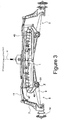
各サスペンション3および5は、下部サスペンションアーム9および上部ウィッシュボーン11に接続された直立部材7(図3参照)を備える。車輪13および15(図1に破線で示す)は各々、直立部材7に回転自在に担持されたハブ14に装着される。
Each suspension 3 and 5 includes an upright member 7 (see FIG. 3) connected to the lower suspension arm 9 and the
直立部材7の前方に延びているのは、トラックロッド延長部19がその外端21に接続されたステアリングアーム17(特に図2参照)である。延長部19の内端はトラックロッド23に接続される。トラックロッド23は、ステアリングコラム29上の第1の揺動自在の接続部27(図2参照)に接続されたリンク25によって横方向に移動する。接続部27は、軸Xを中心に揺動することができるようにコラム29に取り付けられ、かつアーバ31(図6参照)によって車輪33に接続される。車輪33は、39でフレーム1に枢着された揺動アーム37に接続されたケーブル35によって作動するように、コラム29の底部に回転自在に取り付けられる。
Extending forward of the
ピストンロッド43を有するアクチュエータ41は、外端がコイルばね46によって取り囲まれたサスペンションダンパ45のピストンロッド44に接続された、揺動アーム37の1つのアームに作用してアームを枢動させる。各サスペンションシリンダ45の基部は、引込み時にサスペンションが軸Zを中心に揺動するように、51でフレーム1に枢着された引込みアーム49に47で接続される。
The
図4は、延長部19がほぼ垂直の右側サスペンション(図4の左側)を示す。左側サスペンションがほんの1度程度さらに引き込まれると、コラム29の回転は直立部材7の回転に対し何ら効果を持たなくなる。しかし、延長部19が図4の右側に示すように垂直を超えて引込みが行なわれると、ハンドルバー60、コラム29、およびリンク25によって生じるトラックロッド23の動きは再び、車輪を操舵させる。引込み位置ではそれは望まれないが、船舶用ステアリングは必要であるので、図6および7に示す機構が設けられる。
FIG. 4 shows a right suspension (left side in FIG. 4) in which the
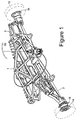
図7は、軸Yを中心に枢動するコラム29にリンク72、73、および74を介して連結された、操舵可能な推進ユニット70、適切にはウォータジェットユニットを模式的に示す。矢印Sは船舶用ステアリング装置の動きを示す。ロードステアリングを無能化または非活動化するために、軸XおよびYは接続部27の枢軸点75で交差するので、軸Yを中心とするコラムの回転は結果的にリンク25における最小限の作動を生じる。
FIG. 7 schematically shows a
図7は、船舶用ステアリングが作動状態であり、ロードステアリングが非活動化された、船舶モードを示す。揺動自在の接続部27は略垂直に、かつ実質的に軸Xに沿って起立するので、ハンドルバー60およびステアリングコラム29の回転は、リンク25およびしたがってトラックロッド13に対し、無視できるほど小さい効果を持つ。したがって、車両が水上で操舵されたときに、路面車輪はほんのわずか動くだけである。路面車輪が図3に示す伸出位置から、図4に示す引込み位置まで引き込まれると、揺動アーム37はシリンダ41(図2)によって回転し、サスペンションおよびしたがって車輪の前記引込みを生じる。揺動アーム37が回転すると、ケーブル35の近端が引っ張られる。したがってケーブル35の遠端は車輪33を回転させ、それは次にアーバ31およびしたがって接続部27を、接続部27が略垂直になるまで、図6のRの方向に回転させる。
FIG. 7 shows a ship mode in which the ship steering is activated and the road steering is deactivated. Since the
車輪の伸出を達成するために、シリンダ41が延長し、揺動アーム37が伸出の場合とは逆の意味で回転する。次いでケーブル35が押され、図6に示すように接続部27が略水平になるまで、車輪33が図7のPの方向に回転する。接続部27の遠端は今、軸Xから半径の位置にあるので、再び、リンク25およびトラックロッド23を介して車両を操舵することが可能である。船舶用ステアリングはこの陸上モードで依然として係合されているが、陸上では水がジェットドライブを通過しないので、ステアリングバケットを左右に揺動する以外の効果を持たない。
In order to achieve the extension of the wheel, the
陸上でのロードステアリングの偶発的な脱離を防止するために、ロックを設けて接続部27を略水平位置に維持することは簡単である。これを達成する最も単純な方法は、船舶モードから陸上モードへのモード切替えが完了すると接続部27をロックする、ソレノイド駆動ピンを設けることである。そのような電気駆動装置の使用は、ピン発射信号を船舶モードから陸上モードへの車両モードの切替えの一部とすることができるので、便利である。代替的に、選好に応じて流体動力または空気動力を使用することができる。
In order to prevent accidental detachment of the road steering on land, it is easy to provide a lock and maintain the connecting
揺動自在の接続部27は、他の実施形態では、サスペンションとは独立して、レバー33’またはモータ(特にステッパモータ)33"(図8および9参照)を用いて移動させることができる。図11で、矢印Sは、推進ユニット70のような船舶用ステアリング装置を制御するリンク機構73の移動を表わす。
In other embodiments, the
図10および11に示すさらなる実施形態では、第2の揺動自在の接続部74’が、軸Zを中心に枢動するようにロッド90の下端に取り付けられる。ロッド90は、カラムの軸線Y上を軸方向に、図10の不作動位置から図11の作動位置まで移動可能である。前出の実施例と同様にリンク機構73を介して操舵可能なポンプジェットダクト70に接続された第2接続部を非活動化するために、ロッド90はノブ91によってロック位置(図11)から下部位置に下降され、そこで当接手段として働くベアリングまたはリングブロック92に当接することによって、接続部74’は軸Zを中心に上方に揺動する。
In a further embodiment shown in FIGS. 10 and 11, a second
本発明の本質的な概念から逸脱することなく、上述したステアリング装置にさらなる改善を施すことができることに注目されたい。例えば、WO02/44006号として公開された出願人の同時係属出願に記載されているように、各路面車輪に対し個々の引込み装置を設けることができる。サスペンションはコイルばねを使用しなくてもよく、WO01/74612号として公開された出願人の同時係属出願に記載されているように、トーションバー、または複合流体ばね、ダンパ、および引込みユニットを使用することができる。代替的に、車輪引込みは空気動力により、または電気的に作動することができる。ステアリング機構は補助動力を持つことができる。船舶駆動装置はオープンプロペラまたはダクテッドプロペラとすることができる。 It should be noted that further improvements can be made to the steering device described above without departing from the essential concepts of the present invention. For example, as described in the applicant's co-pending application published as WO02 / 44006, an individual retracting device can be provided for each road wheel. The suspension does not need to use a coil spring and uses a torsion bar, or a composite fluid spring, a damper, and a retracting unit, as described in Applicant's co-pending application published as WO01 / 74612. be able to. Alternatively, wheel retraction can be actuated pneumatically or electrically. The steering mechanism can have auxiliary power. The ship drive can be an open propeller or a ducted propeller.
Claims (12)
(i)ステアリングコラムに接続され、ステアリングコラム軸を中心に前記コラムを回転させるように構成された手動ステアリング手段と、
(ii)内端が前記コラムに枢着され、その枢軸が前記コラム軸と実質的に交差するように構成された揺動自在な第1接続部と、
(iii)前記第1接続部の外端が、前記路面車輪ステアリング手段および前記船舶用ステアリング手段の少なくとも1つに接続されていることと、
(iv)前記第1接続部の内端から外端への方向が前記コラム軸に対し略垂直である作動位置から、前記第1接続部の前記方向がコラム軸と略平行である不作動位置まで前記第1接続部を揺動させるための操作手段と、を組み合わせて含む車両用ステアリング装置。An amphibious vehicle steering apparatus having road wheel steering means and marine steering means, comprising at least:
(I) manual steering means connected to the steering column and configured to rotate the column about a steering column axis;
(Ii) a swingable first connection portion having an inner end pivotally attached to the column, the pivot shaft substantially intersecting the column shaft;
(Iii) an outer end of the first connection portion is connected to at least one of the road surface wheel steering means and the marine vessel steering means ;
(Iv) substantially from a working position which is perpendicular, the direction inoperative position substantially parallel to the column axis of the first connecting portion direction relative to the column axis to the outer end from the inner end of the first connecting portion And a steering device for a vehicle including a combination of operating means for swinging the first connecting portion .
Applications Claiming Priority (3)
| Application Number | Priority Date | Filing Date | Title |
|---|---|---|---|
| GB0423483.7 | 2004-10-22 | ||
| GB0423483A GB2419332A (en) | 2004-10-22 | 2004-10-22 | Steering arrangement with retractable wheels |
| PCT/GB2005/004088 WO2006043094A2 (en) | 2004-10-22 | 2005-10-21 | Vehicle steering arrangements |
Publications (3)
| Publication Number | Publication Date |
|---|---|
| JP2008517817A JP2008517817A (en) | 2008-05-29 |
| JP2008517817A5 JP2008517817A5 (en) | 2008-07-10 |
| JP4860627B2 true JP4860627B2 (en) | 2012-01-25 |
Family
ID=33485020
Family Applications (1)
| Application Number | Title | Priority Date | Filing Date |
|---|---|---|---|
| JP2007537391A Expired - Fee Related JP4860627B2 (en) | 2004-10-22 | 2005-10-21 | Vehicle steering device |
Country Status (9)
| Country | Link |
|---|---|
| US (1) | US7618050B2 (en) |
| EP (1) | EP1819535B1 (en) |
| JP (1) | JP4860627B2 (en) |
| CN (1) | CN101065255A (en) |
| AT (1) | ATE503642T1 (en) |
| AU (1) | AU2005297093A1 (en) |
| DE (1) | DE602005027240D1 (en) |
| GB (1) | GB2419332A (en) |
| WO (1) | WO2006043094A2 (en) |
Families Citing this family (7)
| Publication number | Priority date | Publication date | Assignee | Title |
|---|---|---|---|---|
| GB2419327B (en) | 2004-10-22 | 2007-10-10 | Gibbs Tech Ltd | Amphibious vehicle transmission |
| GB2452092B (en) * | 2007-08-24 | 2010-06-23 | Gibbs Tech Ltd | Improvements in or relating to amphibians |
| GB2461081B (en) * | 2008-06-19 | 2011-12-28 | Gibbs Tech Ltd | A three-wheeled amphibian with retractable wheels |
| WO2013093972A1 (en) * | 2011-12-21 | 2013-06-27 | トヨタ自動車株式会社 | Steering device |
| GB2551683B (en) * | 2015-05-07 | 2019-01-30 | Gibbs Tech Ltd | A retractable wheel assembly for an amphibian |
| CN106042809A (en) * | 2016-07-13 | 2016-10-26 | 安徽工程大学机电学院 | Airphibian drop-resistant multi-axis air vehicle |
| CN113022889B (en) * | 2021-04-06 | 2022-07-12 | 哈尔滨工业大学 | Wheel-step composite planetary inspection vehicle and walking method |
Citations (4)
| Publication number | Priority date | Publication date | Assignee | Title |
|---|---|---|---|---|
| JPH04208611A (en) * | 1990-11-30 | 1992-07-30 | Isuzu Motors Ltd | Steering device for amphibian vehicle |
| US5531179A (en) * | 1994-02-25 | 1996-07-02 | Roycroft; Terence J. | Wheel-retraction apparatus and method for amphibious vehicle |
| US5590617A (en) * | 1992-06-23 | 1997-01-07 | Aquastrada International Corporation | Amphibious vehicle |
| WO2003037663A1 (en) * | 2001-11-01 | 2003-05-08 | Gibbs Technologies Limited | Steering system |
Family Cites Families (11)
| Publication number | Priority date | Publication date | Assignee | Title |
|---|---|---|---|---|
| US3280785A (en) * | 1965-03-01 | 1966-10-25 | George H Mycroft | Amphibious structure |
| US3755835A (en) * | 1971-08-13 | 1973-09-04 | H Boersig | Wheeled boat |
| JPH0524420A (en) | 1991-07-19 | 1993-02-02 | Isuzu Motors Ltd | Steering device for amphibious vehicle |
| DE9319878U1 (en) * | 1993-12-23 | 1994-06-09 | Ec Eng & Consult Spezialmasch | Steering device |
| US5687669A (en) * | 1995-12-08 | 1997-11-18 | Engler; Manfred W. | Amphibious vehicle |
| US5727494A (en) * | 1996-09-26 | 1998-03-17 | Caserta; Anthony L. | Amphibious vehicle |
| GB0007625D0 (en) | 2000-03-30 | 2000-05-17 | Gibbs Tech Ltd | Improved suspension strut |
| JP4705312B2 (en) * | 2000-09-30 | 2011-06-22 | ギブズ テクノロジーズ リミテッド | Steering system |
| GB0029298D0 (en) | 2000-12-01 | 2001-01-17 | Gibbs Int Tech Ltd | Suspension arrangement |
| AU2003278497A1 (en) | 2002-06-20 | 2004-01-06 | Evotec Neurosciences Gmbh | Diagnostic and therapeutic use of ras-gtpase-activating sh3-domain-binding protein 2 (g3bp2) for neurodegenerative diseases |
| GB2400082B (en) | 2003-03-31 | 2005-02-16 | Gibbs Tech Ltd | Amphibious vehicle suspension |
-
2004
- 2004-10-22 GB GB0423483A patent/GB2419332A/en not_active Withdrawn
-
2005
- 2005-10-21 EP EP05796699A patent/EP1819535B1/en not_active Not-in-force
- 2005-10-21 CN CNA2005800361418A patent/CN101065255A/en active Pending
- 2005-10-21 AT AT05796699T patent/ATE503642T1/en not_active IP Right Cessation
- 2005-10-21 US US11/256,204 patent/US7618050B2/en active Active
- 2005-10-21 JP JP2007537391A patent/JP4860627B2/en not_active Expired - Fee Related
- 2005-10-21 AU AU2005297093A patent/AU2005297093A1/en not_active Abandoned
- 2005-10-21 DE DE602005027240T patent/DE602005027240D1/en active Active
- 2005-10-21 WO PCT/GB2005/004088 patent/WO2006043094A2/en active Application Filing
Patent Citations (4)
| Publication number | Priority date | Publication date | Assignee | Title |
|---|---|---|---|---|
| JPH04208611A (en) * | 1990-11-30 | 1992-07-30 | Isuzu Motors Ltd | Steering device for amphibian vehicle |
| US5590617A (en) * | 1992-06-23 | 1997-01-07 | Aquastrada International Corporation | Amphibious vehicle |
| US5531179A (en) * | 1994-02-25 | 1996-07-02 | Roycroft; Terence J. | Wheel-retraction apparatus and method for amphibious vehicle |
| WO2003037663A1 (en) * | 2001-11-01 | 2003-05-08 | Gibbs Technologies Limited | Steering system |
Also Published As
| Publication number | Publication date |
|---|---|
| WO2006043094A2 (en) | 2006-04-27 |
| US7618050B2 (en) | 2009-11-17 |
| EP1819535B1 (en) | 2011-03-30 |
| GB0423483D0 (en) | 2004-11-24 |
| EP1819535A2 (en) | 2007-08-22 |
| GB2419332A (en) | 2006-04-26 |
| DE602005027240D1 (en) | 2011-05-12 |
| ATE503642T1 (en) | 2011-04-15 |
| CN101065255A (en) | 2007-10-31 |
| AU2005297093A1 (en) | 2006-04-27 |
| WO2006043094A3 (en) | 2006-08-24 |
| JP2008517817A (en) | 2008-05-29 |
| US20060178058A1 (en) | 2006-08-10 |
Similar Documents
| Publication | Publication Date | Title |
|---|---|---|
| JP4860627B2 (en) | Vehicle steering device | |
| US11485182B2 (en) | Amphibians | |
| JP2010520120A5 (en) | ||
| JPH0333559B2 (en) | ||
| US20070001419A1 (en) | Retractable leg assembly for amphibious vehicle | |
| US4809805A (en) | Articulated vehicle | |
| CA2728415C (en) | Amphibian | |
| JP2008517817A5 (en) | ||
| US4813897A (en) | Combined trim, tilt and lift apparatus for a marine propulsion device | |
| EP2203321A1 (en) | Amphibian | |
| US4079807A (en) | Steering mechanism | |
| US20050034646A1 (en) | Retractable road wheel and steering arrangement for an amphibious vehicle | |
| US20110117798A1 (en) | Steering device for outboard engine | |
| CA1322992C (en) | Stone-laying machine | |
| JP2016097766A (en) | vehicle | |
| JPS5945295A (en) | Spring-up device for outboard motor | |
| AU2002329493A1 (en) | A retractable road wheel and steering arrangement for an amphibious vehicle | |
| JPH034439B2 (en) | ||
| JPH10218097A (en) | Steering device for yacht | |
| JPS5822793A (en) | Tilt guide device for interior or outboard engine | |
| JPH037679A (en) | Structure of steering part of working vehicle | |
| GB2449889A (en) | An outboard motor steering system |
Legal Events
| Date | Code | Title | Description |
|---|---|---|---|
| A521 | Request for written amendment filed |
Free format text: JAPANESE INTERMEDIATE CODE: A523 Effective date: 20080411 |
|
| A621 | Written request for application examination |
Free format text: JAPANESE INTERMEDIATE CODE: A621 Effective date: 20080411 |
|
| A131 | Notification of reasons for refusal |
Free format text: JAPANESE INTERMEDIATE CODE: A131 Effective date: 20100803 |
|
| A601 | Written request for extension of time |
Free format text: JAPANESE INTERMEDIATE CODE: A601 Effective date: 20101102 |
|
| A602 | Written permission of extension of time |
Free format text: JAPANESE INTERMEDIATE CODE: A602 Effective date: 20101110 |
|
| A521 | Request for written amendment filed |
Free format text: JAPANESE INTERMEDIATE CODE: A523 Effective date: 20110203 |
|
| TRDD | Decision of grant or rejection written | ||
| A01 | Written decision to grant a patent or to grant a registration (utility model) |
Free format text: JAPANESE INTERMEDIATE CODE: A01 Effective date: 20111004 |
|
| A01 | Written decision to grant a patent or to grant a registration (utility model) |
Free format text: JAPANESE INTERMEDIATE CODE: A01 |
|
| A61 | First payment of annual fees (during grant procedure) |
Free format text: JAPANESE INTERMEDIATE CODE: A61 Effective date: 20111102 |
|
| R150 | Certificate of patent or registration of utility model |
Free format text: JAPANESE INTERMEDIATE CODE: R150 |
|
| FPAY | Renewal fee payment (event date is renewal date of database) |
Free format text: PAYMENT UNTIL: 20141111 Year of fee payment: 3 |
|
| R250 | Receipt of annual fees |
Free format text: JAPANESE INTERMEDIATE CODE: R250 |
|
| R250 | Receipt of annual fees |
Free format text: JAPANESE INTERMEDIATE CODE: R250 |
|
| R250 | Receipt of annual fees |
Free format text: JAPANESE INTERMEDIATE CODE: R250 |
|
| LAPS | Cancellation because of no payment of annual fees |