JP4860103B2 - Apparatus for producing a deposit package - Google Patents
Apparatus for producing a deposit package Download PDFInfo
- Publication number
- JP4860103B2 JP4860103B2 JP2003337963A JP2003337963A JP4860103B2 JP 4860103 B2 JP4860103 B2 JP 4860103B2 JP 2003337963 A JP2003337963 A JP 2003337963A JP 2003337963 A JP2003337963 A JP 2003337963A JP 4860103 B2 JP4860103 B2 JP 4860103B2
- Authority
- JP
- Japan
- Prior art keywords
- deposit
- package
- support member
- support
- pressing
- Prior art date
- Legal status (The legal status is an assumption and is not a legal conclusion. Google has not performed a legal analysis and makes no representation as to the accuracy of the status listed.)
- Expired - Fee Related
Links
Images


Classifications
-
- B—PERFORMING OPERATIONS; TRANSPORTING
- B65—CONVEYING; PACKING; STORING; HANDLING THIN OR FILAMENTARY MATERIAL
- B65H—HANDLING THIN OR FILAMENTARY MATERIAL, e.g. SHEETS, WEBS, CABLES
- B65H33/00—Forming counted batches in delivery pile or stream of articles
- B65H33/02—Forming counted batches in delivery pile or stream of articles by moving a blade or like member into the pile
-
- B—PERFORMING OPERATIONS; TRANSPORTING
- B65—CONVEYING; PACKING; STORING; HANDLING THIN OR FILAMENTARY MATERIAL
- B65H—HANDLING THIN OR FILAMENTARY MATERIAL, e.g. SHEETS, WEBS, CABLES
- B65H2301/00—Handling processes for sheets or webs
- B65H2301/40—Type of handling process
- B65H2301/42—Piling, depiling, handling piles
- B65H2301/421—Forming a pile
- B65H2301/4214—Forming a pile of articles on edge
- B65H2301/42146—Forming a pile of articles on edge by introducing articles from above
-
- B—PERFORMING OPERATIONS; TRANSPORTING
- B65—CONVEYING; PACKING; STORING; HANDLING THIN OR FILAMENTARY MATERIAL
- B65H—HANDLING THIN OR FILAMENTARY MATERIAL, e.g. SHEETS, WEBS, CABLES
- B65H2301/00—Handling processes for sheets or webs
- B65H2301/40—Type of handling process
- B65H2301/42—Piling, depiling, handling piles
- B65H2301/422—Handling piles, sets or stacks of articles
- B65H2301/4223—Pressing piles
-
- B—PERFORMING OPERATIONS; TRANSPORTING
- B65—CONVEYING; PACKING; STORING; HANDLING THIN OR FILAMENTARY MATERIAL
- B65H—HANDLING THIN OR FILAMENTARY MATERIAL, e.g. SHEETS, WEBS, CABLES
- B65H2301/00—Handling processes for sheets or webs
- B65H2301/40—Type of handling process
- B65H2301/42—Piling, depiling, handling piles
- B65H2301/422—Handling piles, sets or stacks of articles
- B65H2301/4224—Gripping piles, sets or stacks of articles
- B65H2301/42242—Gripping piles, sets or stacks of articles by acting on the outermost articles of the pile for clamping the pile
-
- B—PERFORMING OPERATIONS; TRANSPORTING
- B65—CONVEYING; PACKING; STORING; HANDLING THIN OR FILAMENTARY MATERIAL
- B65H—HANDLING THIN OR FILAMENTARY MATERIAL, e.g. SHEETS, WEBS, CABLES
- B65H2301/00—Handling processes for sheets or webs
- B65H2301/40—Type of handling process
- B65H2301/42—Piling, depiling, handling piles
- B65H2301/426—Forming batches
- B65H2301/4263—Feeding end plate or end sheet before formation or after completion of a pile
Landscapes
- Basic Packing Technique (AREA)
- Pile Receivers (AREA)
Description
本発明は、連続して、水平方向に延在する堆積体載置台に供給された、垂直方向に接し合って並べられた、堆積体を形成する印刷紙葉から成る、堆積体パッケージを製造するための装置に関し、この装置が、
印刷紙葉を鱗状に重ねて整列した流れ内において、堆積体載置台に供給する搬送装置、および、1つの堆積体パッケージを形成するために、下からこの堆積体内に食い込む、多部材より成る支持装置から成り、
この支持装置が、待機位置からこの堆積体載置台に沿って、その内においてこの堆積体パッケージが紐掛け装置内に移動可能な押圧装置に引き渡される、引渡し位置に駆動可能であり、且つ、第1の支持部材および第2の支持部材を有しており、
これら支持部材が、下からこの堆積体載置台を過ぎて上昇可能に、および、それぞれに、後方の、または前方の堆積体パッケージの端部に所属して設けられている。
The present invention produces a deposit package consisting of printed paper sheets forming a deposit, arranged in contact with each other in a vertical direction, fed continuously to a deposit mounting table extending in the horizontal direction. This device relates to a device for
A multi-member support that cuts into the stack from below to form a stack package in order to form a stack package in a stream of printed paper sheets stacked and arranged in a scale. Consisting of equipment,
The support device can be driven from the standby position along the deposit body mounting table to a delivery position in which the deposit package is delivered to a pressing device that can move into the strapping device, and 1 support member and a second support member,
These support members are provided so as to be able to ascend past the deposit mounting table from below, and are respectively attached to the end portions of the rear or front deposit packages.
冒頭に記載した様式の装置は、ミュラー・マルチニ(Mueller Martini)の名称アバンティ(Avanti)でもって、ロッド状紙葉集束装置(Stangenausleger)として販売され、且つ、例えばヨーロッパ特許公開623 542号明細書(特許文献1)において記載されている。 A device of the type described at the beginning is sold as a rod-shaped paper-sheet converging device (Stangenausleger) with the name Aveller of Mueller Martini and, for example, European Patent Publication 623 542 ( Patent Document 1).
これら装置は、印刷機械の印刷物引渡し装置と接続されており、この印刷物引渡し装置から、これら装置が、鱗状に重ねて整列した流れ内において堆積する印刷紙葉を受取り、且つ、貯蔵できる束状体へと成形する。ロッド状束状体(Stange)が問題であり、これらが、引き続いて、定期刊行物、雑誌、仮とじ本、等のような、集積された印刷紙葉を有する印刷物へと処理される。 These devices are connected to a printed material delivery device of a printing machine. From the printed material delivery device, these devices can receive and store printed paper sheets accumulated in a stream that is arranged in a scale-like manner and can be stored. To form. Rod-shaped bundles (Stange) are a problem, and these are subsequently processed into printed materials with accumulated printed paper sheets, such as periodicals, magazines, staples, etc.
印刷機械からの排紙処理のため、および更なる処理の準備作業のための、この諸処理工程において、信頼性の損失の無い高い性能が要求される。このことは、具体的に言うと、より短いサイクル時間、ロッド状束状体の長さに関してのより大きな選択、およびロッド状紙葉集束装置でもって形成可能なより短い残余ロッド状束状体を意味している。
ここで、本発明の課題は、それによって所望の目標が達成される、冒頭に記載した様式の装置を提供することである。 The object of the present invention is now to provide a device of the type described at the beginning, whereby the desired goal is achieved.
本発明に従い、この課題は、支持装置が、第3の、紙走行方向で堆積体、または堆積体パッケージの前方の端部に所属して設けられた、上昇可能な支持部材を有していることによって解決される。 In accordance with the invention, this object is achieved by the support device comprising a third support member, which can be raised, belonging to the front end of the deposit or the deposit package in the paper travel direction. It is solved by.
有利には、第3の支持部材は、第1の支持部材および第2の支持部材に依存せずに、堆積体載置台に沿って、駆動可能に制御されており、このことによって、比較的に高い製造性能に対して良い影響を及ぼす動作の自由性が、より多く得られる。 Advantageously, the third support member is drivably controlled along the stack for mounting without depending on the first support member and the second support member, so that More freedom of operation is obtained which has a positive effect on the high manufacturing performance.
有利には、供給された印刷紙葉の鱗状に重ねて整列した流れと、堆積体載置台上に形成された堆積体との間に設けられた分離間隙を形成するための、第1の支持部材および第2の支持部材に所属して設けられた分離装置を有する装置の場合、この第1の支持部材および第2の支持部材は、共に、この分離間隙内へと上昇可能であり、且つ、2つの印刷紙葉の間の正確な分離を生じさせる。 Advantageously, the first support for forming a separation gap provided between the scaled and aligned flow of supplied printing paper sheets and the deposit formed on the deposit table In the case of a device having a separation device provided belonging to the member and the second support member, both the first support member and the second support member can be raised into the separation gap; and This produces an accurate separation between the two printed paper sheets.
堆積体載置台と搬送に有効に接続された、その内において堆積体パッケージが少なくとも1つのベルトでもって紙走行方向で紐掛けされる、紐掛け装置を有する装置の場合、
これら堆積体パッケージは、
堆積体載置台において、合目的には、紙走行方向でこの堆積体パッケージの前方の端部に所属して設けられた押圧部材と、離間されたこの堆積体パッケージの後方の端部に所属して設けられた押圧部材との間で、押圧装置に引き渡され、且つ、
この押圧装置から紐掛け装置に移送され、このことによって、短いサイクル時間が得られる。合目的に、支持装置の支持部材は、共通の、堆積体載置台に対して平行に延在する案内装置に、位置調節可能に設けられており、従って、簡単な案内構造が得られる。
In the case of an apparatus having a strapping device, which is effectively connected to the stack for placing the stack and in which the stack package is strapped in the paper running direction with at least one belt,
These deposit packages are
In the stacking table, the purpose is to belong to the pressing member provided to belong to the front end of this stacking package in the paper traveling direction and to the rear end of this separated stacking package. Between the pressing member provided to the pressing device, and
It is transferred from this pressing device to the strapping device, which gives a short cycle time. For the purpose, the support member of the support device is provided in a common guide device extending in parallel to the stacking table so that the position thereof can be adjusted, and thus a simple guide structure can be obtained.
端部側で、終端板でもって補強された堆積体パッケージを製造するための、堆積体載置台に沿って設けられた終端板供給装置を有する装置の場合、
堆積体パッケージの後方の端部のために規定された終端板が、
この堆積体パッケージの後方の端部に当接する第2の支持部材と、この堆積体パッケージの後方の端部に所属して設けられた押圧部材との間の、この堆積体パッケージの引渡し位置において、堆積体載置台に供給され、
それによって、信頼性の高い終端板位置決めが、この堆積体載置台上で保証されている。
In the case of an apparatus having a termination plate supply device provided along a deposit mounting table for manufacturing a deposit package reinforced with a termination plate on the end side,
A termination plate defined for the rear edge of the deposit package,
At the delivery position of the deposit package between the second support member that contacts the rear end of the deposit package and the pressing member provided to belong to the rear end of the deposit package , Is supplied to the stacking table,
Thereby, reliable end plate positioning is assured on this stack.
同じ目的のために、堆積体パッケージの前方の端部のために規定された終端板は、第2の支持部材および第3の支持部材によって形成された間隙内において、堆積体載置台上において、紙走行方向に逆らって移送される。 For the same purpose, the end plate defined for the front end of the deposit package is on the deposit table in the gap formed by the second and third support members. It is transported against the paper running direction.
有利には、終端板のための供給装置は、引渡し位置内において存在する押圧装置の押圧部材の間に配設されており、このことによって、それぞれに所望の長さの堆積体パッケージが製造され得る。 Advantageously, the supply device for the end plate is arranged between the pressing members of the pressing device present in the delivery position, whereby a deposit package of the desired length is produced for each. obtain.
押圧装置が、堆積体載置台の上方でこの堆積体載置台に対して平行に指向する走行レールに沿って移動可能である場合、簡単な構造であることは明らかである。 It is clear that the structure is simple if the pressing device is movable above the deposit mounting table along a running rail oriented parallel to the deposit mounting table.
引き続いて、本発明を、説明の内において詳しくは述べられていない全ての詳細な事項に関して参照するように指示されている図に関連して、1つの実施例、および、この実施例に図示された処理方法に基づいて説明する。 Subsequently, the present invention is illustrated in one embodiment and in this embodiment with reference to the drawings directed to refer to all the details not described in detail in the description. The processing method will be described.
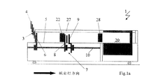
図1aから、1lまでは、連続して、鱗状に重ねて整列した流れ3でもって供給された印刷紙葉4から成る、堆積体パッケージ2を製造するための装置1を示している。これら印刷紙葉4が前もって整向され、且つ所望の鱗状に重ねた形状に移動された後に、これら印刷紙葉4は、ヨーロッパ特許公開623 542号明細書(特許文献1)に記載されているように、搬送装置を介して、(図示されていない)鱗状に重ねて整列した流れ3でもって、水平方向の堆積体載置台5に供給され、即ち、鱗状に重ねた形成物が、印刷機械に従って、側方に180°だけ向きを変えられねばならない。
FIGS. 1 a to 1 l show an apparatus 1 for producing a
この鱗状に重ねた形成物が、巻体(Wickel)から処理されねばならない場合、先ず第一に、他の巻体上への巻き替えが必須である。図1aから1lまでは、更に、装置1が移動可能に構成されていること、および従って、ある作業の異なる印刷機械の印刷物引渡し装置に接続可能であることを示している。 If this scale-like formation has to be processed from a wound body (Wickel), first of all it is essential to rewind onto another wound body. FIGS. 1 a to 1 l further show that the device 1 is configured to be movable and can therefore be connected to a print delivery device of a different printing machine for certain operations.
図1aは、走入する鱗状に重ねて整列した流れ3の際の、および、堆積体載置台5を過ぎて上昇された、多部材より成る支持装置7の第1の支持部材6の際の、空の状態における装置1を示している。この支持装置は、更に、第2の支持部材8を備えており、この第2の支持部材が、同様に、上昇された状態において具体的に説明されている。これら両方の支持部材6、8に、第3の支持部材9が、所属して設けられており、この第3の支持部材が、同様に、突き出された状態において図示されている。これら支持装置7を形成する支持部材6、8、9は、この堆積体載置台5の下方で、この堆積体載置台に対して平行に設けられた案内装置10において、堆積体載置台5に沿って駆動されている。
FIG. 1 a shows the
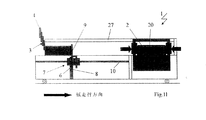
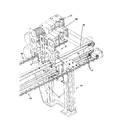
上記の目的で、支持部材6、8、9は、例えば、堆積体載置台5に沿って、紙走行方向に、および引き返して駆動される、歯付きベルト、またはチェーンのような牽引手段と結合されており、且つ、制御された調節手段によって上昇および降下され得る。支持装置7、特に支持部材9のための駆動装置の1つの実施例は、図2において図示されている。この図2は、装置1のフレームに固定された側方の案内装置10を示しており、この案内装置に、堆積体載置台5に沿って移動可能な走行機構11が設けられており、この走行機構に、この支持部材9が、上昇および降下可能に案内されている。この目的のために、2つの支柱12が設けられており、これら支柱に沿って、3つの支持板13を有する支持部材9が、空気圧シリンダー(図示されていない)によって、垂直方向に駆動可能である。この堆積体載置台5に沿っての支持部材9の駆動は、歯付きベルト14によって行われ、この歯付きベルトに関して、上側の車間部分と同様に、下側の車間部分も認識可能である。この歯付きベルト14のための駆動モータは、この堆積体載置台5の反対側の端部に設けられている。歯付きベルト15は、支持部材6の駆動のために、および、歯付きベルト16が支持部材8のために設けられている。これら歯付きベルト15から17までは、それぞれに、プーリを中心として方向を転換され、これらプーリによって、1つの歯付きベルトが1つの駆動モータと結合されており、その際、歯付きベルト16に駆動モータ17が、歯付きベルト15に駆動モータ18が所属して設けられている。これら支持部材6、8は、支持部材9のように、自身の走行機構(図2においては具体的に説明されていない)に固定されており、且つ、この支持部材9のように、空気圧シリンダーによって操作可能である。図1aにおいて、この堆積体載置台5の上方で、この堆積体載置台に沿って移動可能な押圧装置19が設けられており、この押圧装置は、堆積体載置台5上で製造された堆積体パッケージ2を囲繞し、且つ引き続いての紐掛け装置20内へ移送する。
For the above purpose, the
押圧装置19の内、図3において、押圧部材22を有する担持機構21が、紙走行方向とは逆に見た状態で図示されている。この担持機構は、この紙走行方向に対して横方向に延在し、且つ両側で、2つのローラ23によって、固定のC字形の走行レール内において(図では目視できない)、移動可能に配設されている。下側面に、この走行レール27は、ラック(図示されていない)を備えており、このラックと、それぞれ1つの、走行駆動装置25の歯車24が噛み合っている。この押圧部材22は、2つの押圧板31から成り、これら押圧板が、それらの上方に設けられた案内ロッド26に沿って、紙走行方向に対して横方向に、処理されるべき印刷紙葉のサイズに対して位置調節可能である。押圧装置19の動作領域は、堆積体載置台5から紐掛け装置20内へと延在している。この堆積体載置台5に沿って、紙走行方向に先行して走る押圧部材28が設けられており、この押圧部材28が、押圧部材22と共に押圧装置19を形成し、この押圧装置19が、図1aにおいて、出発位置に存在している。堆積体形成の開始の際、支持装置7の支持部材6、9は、堆積体載置台5を過ぎて上方に移動された、まさに終端板29の受取りの状態で存在し、この終端板が、装置1の傍らで、離間された支持部材8、9の間の板マガジンから移動される。図示された場合において、この終端板29が問題であり、この終端板は、紙走行方向において前方の、堆積体、または堆積体パッケージ2の端部のために設けられている。この(前方の)終端板29は、ここで、支持部材8、9の間で、堆積体載置台5の上を通過して、1つの堆積体の前方の、支持部材6によって直立した状態で保持される堆積体端部に案内される。図1bにおいて、そうこうしている間に、第2の支持部材8が、堆積体載置台5から下に向かって離れ、且つ、この終端板29が、ここで、支持部材6と9の間に保持される。集積工程は、その場合に維持され、且つ、支持装置7の第1の支持部材6が、ここで、同様に下に向かって移動され、従って、終端板29が、支持部材9によって支持された状態で、前方の堆積体端部に当接の状態になる(図1c参照)。この堆積体が、この堆積体載置台5上で更に堆積する間に、これら支持部材6、8は、後方の堆積体端部の前のこれら支持部材の出発位置に移動していく(図1d参照)。
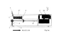
In FIG. 3, the holding mechanism 21 having the pressing
図1eによる状況において、堆積体パッケージ2は、支持部材9によって直立に状態維持された終端板29と、第2の支持部材8との間に存在し、この第2の支持部材が、支持部材6と共に出発位置から、紙葉分離位置に移動され、且つ、支持部材6、8に所属して設けられた、例えばヨーロッパ特許公開623 542号明細書(特許文献1)において記載されているような紙葉分離装置によって、到着する鱗状に重ねて整列した流れ3を、堆積開始部の前で遮断する。この図示されていない紙葉分離装置は、間隙を形成し、この間隙内に、引き続いて、これら支持部材6および8が、共に挿入される。支持部材6は、後に続く堆積体の、前方の端部における支持機能を引き受け、且つ、支持部材8が堆積体パッケージ2の後方の端部を支持する。
In the situation according to FIG. 1e, the
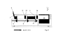
堆積体形成が、連続的に継続される間、支持部材8、および9は、堆積体パッケージ2を、押圧装置19によって引き取られるべき位置に移送する。この位置において(図1f参照)、この堆積体パッケージ2は、この押圧装置19の2つの押圧部材22、28の間に存在し、従って、この堆積体パッケージ2の後方の端部に、終端板30が、側方の終端板マガジンから供給され、即ち、この終端板マガジンは、押圧部材22、28の間で、後方の堆積体パッケージ端部のための押圧部材に、近接して配設されている。この押圧部材22、および後方の堆積体パッケージ端部、即ちこの堆積体パッケージ端部を支持する支持部材8は、間隙を形成し、この間隙内に、後方の終端板30が挿入される。両方の終端板29および30は、同じ大きさを有している(図1g参照)。
While the deposit formation continues continuously, the
引き続いて、図1hにより、紙走行方向において前方の押圧部材28、および後方の押圧部材22が、それらの間にある終端板29および30と共に、堆積体パッケージ2の端部に当接し、且つ、同時に、支持部材8、9が、堆積体領域から外される。その間に、堆積体形成は、鱗状に重ねて整列した流れの終期にあっても継続される。
Subsequently, according to FIG. 1h, the
押圧部材22、28によって捕捉された堆積体パッケージ2は、ここで、走行レール27に沿って、紐掛け装置20内へと移送され、且つ、支持部材8、9が、前方の終端板29の受取りのために、終端板マガジンに到着する。
The
前方の終端板29は、継続的に増大する堆積体の前方の堆積体端部に移動されるその間に、この堆積体パッケージ2は、紐掛け装置20内において、最終的に押圧され、且つ、引き続いて紐掛け、即ち束ねられる。
While the
図1lにおいて、前方の終端板29が、支持部材9によって支持された状態で、前方の堆積体端部に接して立っており、支持部材6、8が外されており、且つ紐掛けが実施されている。これら支持部材6、8は、次の工程において、図1dにより新しい堆積プロセスが既に開始した出発位置に帰還する。
In FIG. 11, the
1 装置
2 堆積体パッケージ
3 鱗状に重ねて整列した流れ
4 印刷紙葉
5 堆積体載置台
6 第1の支持部材
7 支持装置
8 第2の支持部材
9 第3の支持部材
10 案内装置
11 走行機構
12 支柱
13 支持板
14 歯付きベルト
15 歯付きベルト
16 歯付きベルト
17 駆動モータ
18 駆動モータ
19 押圧装置
20 紐掛け装置
21 担持機構
22 押圧部材
23 ローラ
24 歯車
25 走行駆動装置
26 案内ロッド
27 走行レール
28 押圧部材
29 終端板
30 終端板
DESCRIPTION OF SYMBOLS 1
Claims (9)
印刷紙葉(4)を鱗状に重ねて整列した流れ(3)内において、堆積体載置台(5)に供給する搬送装置、および、1つの堆積体パッケージ(2)を形成するために、下からこの堆積体内に挿入される、多部材より成る支持装置(7)から成り、
この支持装置が、第1の支持部材(6)および第2の支持部材(8)を有しており、この支持装置(7)の第2の支持部材(8)が、待機位置からこの堆積体載置台(5)に沿って、その内においてこの堆積体パッケージ(2)が紐掛け装置(20)内に移動可能な押圧装置(19)に引き渡される、引渡し位置に駆動可能であり、
これら支持部材が、下からこの堆積体載置台(5)を過ぎて上昇可能に、および、それぞれに、後方の、または前方の堆積体パッケージ(2)の端部に割り当てられている様式の上記装置において、
支持装置(7)が、第3の、紙走行方向で堆積体、または堆積体パッケージ(2)の前方の端部に割り当てられた、上昇可能な支持部材(9)を有しており、
支持装置(7)の支持部材(6、8、9)は、共通の案内装置(10)に、位置調節可能に設けられていること、および、押圧装置(19)は、堆積体載置台(5)の上方に配設された走行レール(27)に沿って移動可能に形成されていることいること、
押圧装置(19)は、二つの押圧部材(22,28)からなり、これら二つの押圧部材(22,28)の間に堆積体パッケージ(2)を囲繞し、引き続く紐掛け装置(20)内へ移送することを特徴とする装置。 It consists of a printed paper sheet (4) that is continuously supplied in a horizontal direction and is arranged in contact with a vertical direction with respect to the paper traveling direction to form a stack. An apparatus (1) for manufacturing a deposit package (2), the apparatus comprising:
In order to form a transport device for feeding the deposit body mounting table (5) and one deposit body package (2) in a flow (3) in which printed paper sheets (4) are arranged in a scale-like manner, Comprising a multi-member support device (7) inserted into the stack from
The support device includes a first support member (6) and a second support member (8), and the second support member (8) of the support device (7) is deposited from the standby position. Along the body mounting table (5), the stack package (2) can be driven to a delivery position where it is delivered to a pressing device (19) which can be moved into a stringing device (20) ,
Form these support members, raisable the past base (5) mounting the stack from below, and each, allocated to the end of the rear or front of the stack package, (2) In the above apparatus,
The support device (7) has a liftable support member (9) assigned to the front end of the deposit, or deposit package (2), in the third, paper travel direction;
The support members (6, 8, 9) of the support device (7) are provided in a common guide device (10) so that the position can be adjusted, and the pressing device (19) 5) being formed so as to be movable along the traveling rail (27) disposed above ,
The pressing device (19) includes two pressing members (22, 28), surrounds the deposit package (2) between the two pressing members (22, 28), and continues in the stringing device (20). A device characterized by being transported to
第1の支持部材(6)および第2の支持部材(8)は、共に、この分離間隙内へと上昇可能であるように構成されていることを特徴とする上記の装置。 For forming a separation gap provided between the flow (3) aligned in a scale of the supplied printing paper sheet (4) and the deposit formed on the deposit mounting table (5) The apparatus according to claim 1 or 2, comprising a separation device attached to the first support member (6) and the second support member (8).
The device as described above, characterized in that the first support member (6) and the second support member (8) are both configured to be able to rise into this separation gap.
堆積体パッケージ(2)が、
堆積体載置台(5)において、押圧装置(19)の、紙走行方向でこの堆積体パッケージ(2)の前方の端部に割り当てられた押圧部材(28)と、離間されたこの堆積体パッケージの後方の端部に割り当てられた押圧部材(22)との間に引き渡され、且つ、
この押圧装置から紐掛け装置(20)に移送されるように構成されていることを特徴とする上記の装置。 4. A strapping device (20) connected to the stacking platform (5), in which the stack package (2) is strapped in the paper travel direction with at least one belt. In the apparatus according to any one of
The deposit package (2)
In the deposit base (5), the pressing member (28) assigned to the front end portion of the deposit package (2) in the paper traveling direction of the pressing device (19) and the deposit package separated from each other. passed between the pressing member of the assigned to the ends of the rear (22), and,
Said apparatus characterized by being comprised so that it may be transferred to this stringing apparatus (20) from this press apparatus.
堆積体パッケージ(2)の後方の端部のために規定された終端板(30)が、
この堆積体パッケージ(2)の後方の端部に当接する第2の支持部材(8)と、この堆積体パッケージ(2)の後方の端部に割り当てられた押圧部材(22)との間の、この堆積体パッケージ(2)の引渡し位置において、堆積体載置台(5)に供給されるように構成されていることを特徴とする上記の装置。 On the end side, it has a termination plate supply device provided along a deposit stage (5) for producing a deposit package (2) reinforced with termination plates (29, 30). In the device according to any one of Items 1 to 5,
A termination plate (30) defined for the rear end of the deposit package (2),
Between the 2nd support member (8) contact | abutted at the back end part of this deposit body package (2), and the press member (22) allocated to the back end part of this deposit body package (2) The apparatus is characterized in that it is configured to be supplied to the deposit body mounting table (5) at the delivery position of the deposit body package (2).
Applications Claiming Priority (2)
| Application Number | Priority Date | Filing Date | Title |
|---|---|---|---|
| EP02405851A EP1405809B1 (en) | 2002-10-02 | 2002-10-02 | Device for forming parcels of stacked products |
| EP02405851.3 | 2002-10-02 |
Publications (2)
| Publication Number | Publication Date |
|---|---|
| JP2004123387A JP2004123387A (en) | 2004-04-22 |
| JP4860103B2 true JP4860103B2 (en) | 2012-01-25 |
Family
ID=31985174
Family Applications (1)
| Application Number | Title | Priority Date | Filing Date |
|---|---|---|---|
| JP2003337963A Expired - Fee Related JP4860103B2 (en) | 2002-10-02 | 2003-09-29 | Apparatus for producing a deposit package |
Country Status (4)
| Country | Link |
|---|---|
| US (1) | US7021035B2 (en) |
| EP (1) | EP1405809B1 (en) |
| JP (1) | JP4860103B2 (en) |
| DE (1) | DE50213650D1 (en) |
Families Citing this family (13)
| Publication number | Priority date | Publication date | Assignee | Title |
|---|---|---|---|---|
| ES2319409T3 (en) * | 2002-07-19 | 2009-05-07 | Ferag Ag | PROCEDURE AND DEVICE FOR FORMING AND SHAFING HORIZONTAL BATTERIES (BARS) OF PRINTED PRODUCTS. |
| ITMI20040927A1 (en) * | 2004-05-07 | 2004-08-07 | Omet Srl | PROCEDURE AND DEVICE FOR SEPARATING AND TRANSFERRING TOWARDS THE PACKAGING A NUMBER OF FLAT OBJECTS SUCH AS PAPER SHEETS, IN PARTICULAR NAPKINS |
| DE502006006570D1 (en) * | 2006-02-02 | 2010-05-12 | Mueller Martini Holding Ag | Method and apparatus for forming stacks |
| US20090112675A1 (en) * | 2007-10-31 | 2009-04-30 | Jeff Servais | Automated order fulfillment system and method |
| ATE532729T1 (en) | 2008-08-29 | 2011-11-15 | Mueller Martini Holding Ag | METHOD AND DEVICE FOR PRODUCING STACKS CONSISTING OF PRINTED SHEETS |
| EP2316767B1 (en) | 2009-11-03 | 2012-08-29 | Müller Martini Holding AG | Device and method for manufacturing printed product stacks |
| EP2520525B1 (en) * | 2011-05-03 | 2018-05-23 | Müller Martini Holding AG | Method for manufacturing stacks of vertical printed products |
| EP2537786B1 (en) | 2011-06-22 | 2018-07-18 | Müller Martini Holding AG | Rod-stack and method for manufacturing this rod-stack from printed products |
| DE102011084469A1 (en) | 2011-10-13 | 2013-04-18 | Robert Bosch Gmbh | separating |
| DE102011088625A1 (en) | 2011-12-14 | 2013-06-20 | Müller Martini Holding AG | Device for manufacturing printed products, has conveying device with which printed products are supplied to stacking surface, where movable support device is provided on which stack is supported at leading end |
| EP3590850B1 (en) * | 2018-07-02 | 2021-05-05 | H+H GmbH & Co. KG | Method and device for stacking and packaging of folded products |
| DE102020101506A1 (en) * | 2020-01-23 | 2021-07-29 | MM Engineering GmbH | Device and method for carrying out packaging steps for flat cardboard goods |
| CN113928903A (en) * | 2021-10-18 | 2022-01-14 | 东莞市浩信精密机械有限公司 | Non-stop paper separating mechanism for book binding machine |
Family Cites Families (13)
| Publication number | Priority date | Publication date | Assignee | Title |
|---|---|---|---|---|
| JPS57112266A (en) * | 1980-12-27 | 1982-07-13 | Yamada Kikai Kogyo Kk | Classification device for folded book |
| US4641489A (en) * | 1984-09-28 | 1987-02-10 | World Color Press, Inc. | Machine for handling signatures |
| US4723883A (en) * | 1985-08-09 | 1988-02-09 | Stacker Machine Co., Inc. | Stacker bundler shuttle system |
| US4772003A (en) * | 1987-02-24 | 1988-09-20 | Dainihon Insatsu Kabushiki Kaisha | Apparatus for stacking signatures or the like |
| US4824093A (en) * | 1988-05-06 | 1989-04-25 | Baldwin Technology Corporation | Handling signatures |
| JP2754276B2 (en) * | 1990-05-25 | 1998-05-20 | 凸版印刷株式会社 | Sorting fork drive control method for automatic sorter for printing books |
| DE4117434A1 (en) * | 1991-05-28 | 1992-12-03 | Winkler Duennebier Kg Masch | METHOD AND DEVICE FOR STACKING |
| DE4202540A1 (en) * | 1992-01-30 | 1993-08-05 | Giebeler Gmbh & Co Kg Robert | METHOD AND DEVICE FOR PRODUCING DEFINED STACK OF FOLDED OR UNFOLDED SHEETS OR SHEET-SHAPED OBJECTS |
| JPH06219622A (en) * | 1993-01-20 | 1994-08-09 | Dainippon Printing Co Ltd | Printed sheet accumulating device |
| JP4318322B2 (en) | 1993-05-07 | 2009-08-19 | グラプハ−ホルディング・アクチエンゲゼルシヤフト | Apparatus for forming a stack oriented in a vertical direction with respect to papers standing in parallel |
| IT1274434B (en) * | 1995-05-05 | 1997-07-17 | Civiemme Srl | PROCEDURE FOR SEPARATING PACKAGES OF SIGNATURES IN STACKERS AND STACKER FOR THE EXECUTION OF THE PROCEDURE |
| DE59806580D1 (en) * | 1997-03-18 | 2003-01-23 | Grapha Holding Ag | Device for forming a partial stack which extends perpendicularly to the printed sheets arranged in a row |
| FR2777876B1 (en) * | 1998-04-24 | 2000-06-30 | Realisations Etudes Et Commerc | DEVICE FOR STACKING AND TRANSFERRING PRINTED NOTEBOOKS IN THE FORM OF CARTRIDGES |
-
2002
- 2002-10-02 EP EP02405851A patent/EP1405809B1/en not_active Expired - Lifetime
- 2002-10-02 DE DE50213650T patent/DE50213650D1/en not_active Expired - Lifetime
-
2003
- 2003-09-29 JP JP2003337963A patent/JP4860103B2/en not_active Expired - Fee Related
- 2003-10-02 US US10/676,043 patent/US7021035B2/en not_active Expired - Fee Related
Also Published As
| Publication number | Publication date |
|---|---|
| US20040065214A1 (en) | 2004-04-08 |
| EP1405809A1 (en) | 2004-04-07 |
| EP1405809B1 (en) | 2009-07-01 |
| US7021035B2 (en) | 2006-04-04 |
| JP2004123387A (en) | 2004-04-22 |
| DE50213650D1 (en) | 2009-08-13 |
Similar Documents
| Publication | Publication Date | Title |
|---|---|---|
| JP4860103B2 (en) | Apparatus for producing a deposit package | |
| US7148446B2 (en) | Method and apparatus for laser cutting sheet metal parts | |
| JP4318322B2 (en) | Apparatus for forming a stack oriented in a vertical direction with respect to papers standing in parallel | |
| JPS6351223A (en) | Conveyor feeding sheet of paper to packaging machine | |
| US9003964B2 (en) | Apparatus and method for forming bundles composed of printed products | |
| JP2004338954A (en) | Device for loading printing book on three-way cutter | |
| US6129503A (en) | Combination counter-ejector shingle-output delivery system | |
| TW201934424A (en) | Glass sheet packing system | |
| US5829951A (en) | Collecting and stacking device for laminar sheets and stacking method | |
| JPH04284231A (en) | Separator for bag forming machine and bending machine | |
| US9427927B2 (en) | Apparatus and method for forming stacks of bags | |
| JPH09169465A (en) | Nonstop pile exchanging device in paper discharging device of printing machine | |
| US6711883B2 (en) | Strapping machine for strapping a stack of products | |
| US20030047090A1 (en) | High speed feeding apparatus for clamshell die cutter | |
| JP4762455B2 (en) | Apparatus for the formation of a stack of parallel printed sheets | |
| US5617784A (en) | Apparatus for bundling, transporting, and feeding sheets | |
| KR102314715B1 (en) | Apparatus and method for stack bundling of printed matter | |
| JP3099618B2 (en) | Signature feeder | |
| KR102659385B1 (en) | Station and method for receiving sheet form elements for packaging manufacturing machines | |
| CN220640442U (en) | General baling press | |
| JPS6145858A (en) | Device for alignment and stacking of sheets | |
| JP2754276B2 (en) | Sorting fork drive control method for automatic sorter for printing books | |
| JP3479638B2 (en) | Stacker bundler paper feeder | |
| JPH10310307A (en) | Method of taking out printed matter from carrying passage system and stacking the taken-out printed matter, and equipment therefor | |
| JPH1058384A (en) | Processing method and device for sheet material |
Legal Events
| Date | Code | Title | Description |
|---|---|---|---|
| A621 | Written request for application examination |
Free format text: JAPANESE INTERMEDIATE CODE: A621 Effective date: 20060714 |
|
| A131 | Notification of reasons for refusal |
Free format text: JAPANESE INTERMEDIATE CODE: A131 Effective date: 20090728 |
|
| A601 | Written request for extension of time |
Free format text: JAPANESE INTERMEDIATE CODE: A601 Effective date: 20091027 |
|
| A602 | Written permission of extension of time |
Free format text: JAPANESE INTERMEDIATE CODE: A602 Effective date: 20091030 |
|
| A521 | Written amendment |
Free format text: JAPANESE INTERMEDIATE CODE: A523 Effective date: 20100125 |
|
| RD04 | Notification of resignation of power of attorney |
Free format text: JAPANESE INTERMEDIATE CODE: A7424 Effective date: 20100527 |
|
| A02 | Decision of refusal |
Free format text: JAPANESE INTERMEDIATE CODE: A02 Effective date: 20100921 |
|
| A521 | Written amendment |
Free format text: JAPANESE INTERMEDIATE CODE: A523 Effective date: 20110118 |
|
| A911 | Transfer of reconsideration by examiner before appeal (zenchi) |
Free format text: JAPANESE INTERMEDIATE CODE: A911 Effective date: 20110125 |
|
| A131 | Notification of reasons for refusal |
Free format text: JAPANESE INTERMEDIATE CODE: A131 Effective date: 20110426 |
|
| A521 | Written amendment |
Free format text: JAPANESE INTERMEDIATE CODE: A523 Effective date: 20110721 |
|
| TRDD | Decision of grant or rejection written | ||
| A01 | Written decision to grant a patent or to grant a registration (utility model) |
Free format text: JAPANESE INTERMEDIATE CODE: A01 Effective date: 20111018 |
|
| A01 | Written decision to grant a patent or to grant a registration (utility model) |
Free format text: JAPANESE INTERMEDIATE CODE: A01 |
|
| A61 | First payment of annual fees (during grant procedure) |
Free format text: JAPANESE INTERMEDIATE CODE: A61 Effective date: 20111102 |
|
| R150 | Certificate of patent or registration of utility model |
Free format text: JAPANESE INTERMEDIATE CODE: R150 |
|
| FPAY | Renewal fee payment (event date is renewal date of database) |
Free format text: PAYMENT UNTIL: 20141111 Year of fee payment: 3 |
|
| LAPS | Cancellation because of no payment of annual fees |