JP4859237B2 - Image processing apparatus and method - Google Patents
Image processing apparatus and method Download PDFInfo
- Publication number
- JP4859237B2 JP4859237B2 JP2007050197A JP2007050197A JP4859237B2 JP 4859237 B2 JP4859237 B2 JP 4859237B2 JP 2007050197 A JP2007050197 A JP 2007050197A JP 2007050197 A JP2007050197 A JP 2007050197A JP 4859237 B2 JP4859237 B2 JP 4859237B2
- Authority
- JP
- Japan
- Prior art keywords
- information
- image
- additional information
- embedded
- block
- Prior art date
- Legal status (The legal status is an assumption and is not a legal conclusion. Google has not performed a legal analysis and makes no representation as to the accuracy of the status listed.)
- Expired - Fee Related
Links
Images
Classifications
-
- G—PHYSICS
- G06—COMPUTING; CALCULATING OR COUNTING
- G06T—IMAGE DATA PROCESSING OR GENERATION, IN GENERAL
- G06T1/00—General purpose image data processing
- G06T1/0021—Image watermarking
- G06T1/005—Robust watermarking, e.g. average attack or collusion attack resistant
- G06T1/0064—Geometric transfor invariant watermarking, e.g. affine transform invariant
-
- H—ELECTRICITY
- H04—ELECTRIC COMMUNICATION TECHNIQUE
- H04N—PICTORIAL COMMUNICATION, e.g. TELEVISION
- H04N1/00—Scanning, transmission or reproduction of documents or the like, e.g. facsimile transmission; Details thereof
- H04N1/32—Circuits or arrangements for control or supervision between transmitter and receiver or between image input and image output device, e.g. between a still-image camera and its memory or between a still-image camera and a printer device
- H04N1/32101—Display, printing, storage or transmission of additional information, e.g. ID code, date and time or title
- H04N1/32144—Display, printing, storage or transmission of additional information, e.g. ID code, date and time or title embedded in the image data, i.e. enclosed or integrated in the image, e.g. watermark, super-imposed logo or stamp
- H04N1/32149—Methods relating to embedding, encoding, decoding, detection or retrieval operations
- H04N1/32203—Spatial or amplitude domain methods
-
- H—ELECTRICITY
- H04—ELECTRIC COMMUNICATION TECHNIQUE
- H04N—PICTORIAL COMMUNICATION, e.g. TELEVISION
- H04N1/00—Scanning, transmission or reproduction of documents or the like, e.g. facsimile transmission; Details thereof
- H04N1/32—Circuits or arrangements for control or supervision between transmitter and receiver or between image input and image output device, e.g. between a still-image camera and its memory or between a still-image camera and a printer device
- H04N1/32101—Display, printing, storage or transmission of additional information, e.g. ID code, date and time or title
- H04N1/32144—Display, printing, storage or transmission of additional information, e.g. ID code, date and time or title embedded in the image data, i.e. enclosed or integrated in the image, e.g. watermark, super-imposed logo or stamp
- H04N1/32149—Methods relating to embedding, encoding, decoding, detection or retrieval operations
- H04N1/32267—Methods relating to embedding, encoding, decoding, detection or retrieval operations combined with processing of the image
-
- H—ELECTRICITY
- H04—ELECTRIC COMMUNICATION TECHNIQUE
- H04N—PICTORIAL COMMUNICATION, e.g. TELEVISION
- H04N1/00—Scanning, transmission or reproduction of documents or the like, e.g. facsimile transmission; Details thereof
- H04N1/32—Circuits or arrangements for control or supervision between transmitter and receiver or between image input and image output device, e.g. between a still-image camera and its memory or between a still-image camera and a printer device
- H04N1/32101—Display, printing, storage or transmission of additional information, e.g. ID code, date and time or title
- H04N1/32144—Display, printing, storage or transmission of additional information, e.g. ID code, date and time or title embedded in the image data, i.e. enclosed or integrated in the image, e.g. watermark, super-imposed logo or stamp
- H04N1/32352—Controlling detectability or arrangements to facilitate detection or retrieval of the embedded information, e.g. using markers
-
- G—PHYSICS
- G06—COMPUTING; CALCULATING OR COUNTING
- G06T—IMAGE DATA PROCESSING OR GENERATION, IN GENERAL
- G06T2201/00—General purpose image data processing
- G06T2201/005—Image watermarking
- G06T2201/0051—Embedding of the watermark in the spatial domain
-
- G—PHYSICS
- G06—COMPUTING; CALCULATING OR COUNTING
- G06T—IMAGE DATA PROCESSING OR GENERATION, IN GENERAL
- G06T2201/00—General purpose image data processing
- G06T2201/005—Image watermarking
- G06T2201/0061—Embedding of the watermark in each block of the image, e.g. segmented watermarking
Landscapes
- Engineering & Computer Science (AREA)
- Multimedia (AREA)
- Signal Processing (AREA)
- Physics & Mathematics (AREA)
- General Physics & Mathematics (AREA)
- Theoretical Computer Science (AREA)
- Image Processing (AREA)
- Editing Of Facsimile Originals (AREA)
- Accessory Devices And Overall Control Thereof (AREA)
- Facsimile Image Signal Circuits (AREA)
Description
本発明は、画像情報に付加情報を埋め込む画像処理、並びに、画像情報に埋め込まれた付加情報を抽出する画像処理に関する。 The present invention relates to image processing for embedding additional information in image information, and image processing for extracting additional information embedded in image information.
画像の不正なコピーや改竄などの防止を目的として、画像に特別な情報を埋め込む研究が盛んに行われている。このような技術は、電子透かしと呼ばれる。例えば、写真、絵画などの電子化した画像中に、その著作者名や使用許可に関する情報などの付加情報を埋め込むことが知られている。近年、付加情報を視覚的に目立たないように埋め込んだ画像を、インターネットなどのネットワークを介して、流通させる技術が標準化されつつある。 For the purpose of preventing illegal copying and falsification of images, researches for embedding special information in images have been actively conducted. Such a technique is called a digital watermark. For example, it is known to embed additional information such as information on the author's name and use permission in an electronic image such as a photograph or a picture. In recent years, a technique for distributing an image embedded with additional information so as not to be visually noticeable via a network such as the Internet is being standardized.
また、紙に印刷した画像などの印刷物から、画像を印刷した印刷機器の種類や機体番号などを特定する技術も研究されている。このような技術は、複写機やプリンタなどの画像形成装置の高画質化に伴い、紙幣、印紙、有価証券などの偽造を防止する目的で用いられる。 In addition, a technique for identifying the type of printing device on which an image is printed and the machine number from a printed matter such as an image printed on paper has been studied. Such a technique is used for the purpose of preventing counterfeiting of banknotes, stamps, securities, and the like as the image quality of image forming apparatuses such as copying machines and printers increases.
例えば、特許文献1は、画像の視覚的に感度の低い色差成分、および、彩度成分の高周波域の部分に付加情報を埋め込む技術を開示する。しかし、この技術によって、音声情報やその他の大容量の情報を、印刷の際に目立たないように画像中に埋め込むことは、非常に困難である。
For example,
特許文献2は、誤差拡散法によって生じるテクスチャを利用して、通常の疑似中間調処理では発生しない量子化値の組み合わせを人工的に作成し、その量子化値から作成した符号を画像に埋め込む方法を開示する。この方法によれば、テクスチャの形状が微視的に変化するだけで、元の画像と比較して、視覚的な画質は殆ど変化しない。また、誤差拡散法において量子化閾値を変更することで、極めて容易に異種信号の多重化を実現することができる。
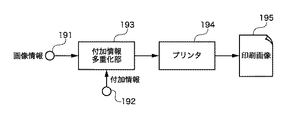
ここで、任意の画像に付加情報を埋め込んで印刷し、さらに、その印刷物から埋め込んだ付加情報を取り出す画像処理システムを説明する。図1は任意の画像に付加情報を埋め込んで印刷する画像処理装置の構成を示すブロック図である。 Here, an image processing system will be described in which additional information is embedded in an arbitrary image for printing, and additional information embedded in the printed matter is taken out. FIG. 1 is a block diagram showing a configuration of an image processing apparatus that prints with additional information embedded in an arbitrary image.
画像処理装置は、入力端子191から任意の多階調の画像情報を入力し、入力端子192から当該画像情報に埋め込む付加情報を入力する。付加情報は、入力端子191から入力する画像情報に関する著作権、撮影日時、撮影場所、撮影者などの諸情報や、あるいは、当該画像情報に全く関係しない音声情報やテキスト情報などである。
The image processing apparatus inputs arbitrary multi-gradation image information from the
付加情報多重化部193は、入力された画像情報中に、入力された付加情報を視覚的に目立たないように埋め込む。すなわち、付加情報多重化部193は、入力された画像情報をN×N画素のブロックに分割し、ブロックごとに付加情報を埋め込む。
The additional
プリンタ194は、付加情報が埋め込まれた画像情報を印刷媒体に印刷して印刷画像195を出力する。なお、プリンタ194は、インクジェットプリンタやレーザビームプリンタなど、疑似中間調処理によって、階調表現が可能なプリンタである。
The
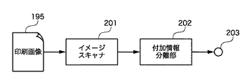
図2は、図1に示す画像処理装置の出力である印刷画像195から、画像情報に埋め込まれた付加情報を取り出す画像処理装置の構成を示すブロック図である。
FIG. 2 is a block diagram illustrating a configuration of an image processing apparatus that extracts additional information embedded in image information from a
画像処理装置は、イメージスキャナ201によって、印刷媒体に印刷された画像情報の画像データを得る。付加情報分離部202は、画像データを入力して、公知の画像処理により、付加情報が埋め込まれた画像領域を検出する。代表的な検出方法としては、非画像領域と画像領域の境界を濃度差によって検知する方法がある。そして、付加情報分離部202は、画像領域を検出した後、同領域に埋め込まれた付加情報を分離し、分離した付加情報を出力端子203に出力する。
The image processing apparatus obtains image data of image information printed on a print medium by the
しかし、上記の画像処理システムには次の問題がある。 However, the above image processing system has the following problems.
まず、入力端子191から入力される画像情報の中には、画像中の濃度差によって画像領域を検出する方法では画像領域の境界が検出できないものがある。画像領域の境界が不明瞭な画像でも、付加情報は目立たないように画像情報中に埋め込まれているので、画像領域を正しく設定する必要がある。例えば、印刷画像195をイメージスキャナ201で読み取る際に、画像領域をトリミングして画像領域を設定すればよいが、ユーザは、どの範囲をトリミングして画像領域に設定すればよいのかわからない場合がある。
First, some image information input from the
さらに、入力画像をN×N画素の複数のブロックに分割し、複数のブロックそれぞれに付加情報から分割された情報が多重化されているため、付加情報分離部202は、各ブロックの領域を多くとも数画素程度の誤差で把握する必要がある。この誤差が大きくなると、付加情報の検出精度が著しく低下し、正確な付加情報を復元することが困難になる。
Furthermore, since the input image is divided into a plurality of blocks of N × N pixels and the information divided from the additional information is multiplexed in each of the plurality of blocks, the additional
特許文献3は、付加情報を埋め込んだ画像領域の周囲に基準マークを所定間隔で配置し印刷する方法を開示する。こうすれば、印刷画像をイメージスキャナで読み取った後、読み取った画像情報から基準マークを検出して、基準マークに従い歪を補正してブロックの領域を高精度に検出することができる。
図3は特許文献3による印刷物の概要を示す図である。印刷媒体232の内側に画像情報231を形成する。そして、画像情報232の周囲に基準マーク233を形成する。印刷媒体232に基準マーク233を形成することで、基準マーク233を検出してN×N画素のブロック234を高精度に検出することができる。
FIG. 3 is a diagram showing an outline of a printed material according to
近年、複写機やプリンタなどの画像形成装置の高機能化に伴い、ディジタルカメラのような撮像装置で撮影した画像を縁なし印刷する機能が装備され、縁なし印刷を行うユーザが増えている。縁なし印刷を実現するために、印刷しようとする画像を印刷媒体より大きなサイズにして、画像の縁が切り取られる形態で印刷する装置が多い。 In recent years, with the enhancement of functions of image forming apparatuses such as copying machines and printers, a function for borderless printing of an image taken by an imaging apparatus such as a digital camera is provided, and the number of users who perform borderless printing is increasing. In order to realize borderless printing, there are many apparatuses that print an image to be printed in a size that is larger than the print medium and in which the edges of the image are cut off.
画像の縁が切り取られる形態で縁なし印刷を実現する装置では、付加情報を埋め込んだ画像領域の検出のために、画像領域の周囲に基準マークを印刷しようとしても、基準マークは切り取られてしまう。 In an apparatus that realizes borderless printing in a form in which an edge of an image is cut off, even if an attempt is made to print a reference mark around the image area in order to detect an image area in which additional information is embedded, the reference mark is cut off. .
図4は特許文献3による印刷物を縁なし印刷した様子を示す図である。縁なし印刷すると、画像情報231の周囲に所定間隔で配置した基準マーク233は、印刷媒体232の外に位置し、基準マーク233は形成されない。勿論、基準マーク233がないため、N×N画素のブロック234を高精度に検出することはできない。言い換えれば、画像領域の周囲に基準マークを配置する方法は、縁なし印刷を考慮すると使えない。
FIG. 4 is a diagram showing a state in which a printed material according to
勿論、印刷媒体232のサイズと、印刷しようとする画像のサイズを一致させて、印刷媒体232と画像の位置がずれないように印刷することができれば、基準マーク233を含む画像を印刷媒体232に印刷することができる。しかし、プリンタの機構上、印刷媒体232と画像の位置がずれないように印刷することは極めて難しい。
Of course, if the size of the
また、特許文献4は、印刷画像領域と同じサイズの領域に付加情報を埋め込み、印刷画像領域のエッジラインを検出して、印刷画像領域と同じサイズの領域に埋め込まれた付加情報を検出する技術を開示する。
図5は特許文献4による印刷物の概要を示す図である。印刷媒体232の内側に印刷画像領域が設定され画像情報231が形成される。画像情報231のサイズに合わせてN×N画素のブロック234が設定されているので、画像情報231のエッジ(印刷画像領域のエッジライン)を検出することができれば、N×N画素のブロック234を高精度に検出することができる。
FIG. 5 is a diagram showing an outline of a printed material according to
図6は特許文献4による印刷物を縁なし印刷した様子を示す図である。縁なし印刷すると、画像の縁が切り取られるため、印刷画像から画像情報のエッジを検出したとしても、印刷前の画像情報231のエッジとは異なり、N×N画素のブロック234を高精度に検出することはできない。
FIG. 6 is a diagram illustrating a state in which a printed material according to
また、印刷画像をイメージスキャナで読み取る際、ユーザにとって、印刷媒体の向きを意識せずに画像を読み取らせ、ブロックを高精度に検出できることが望まれる。 In addition, when reading a print image with an image scanner, it is desirable for the user to be able to read the image without regard to the orientation of the print medium and to detect the block with high accuracy.
あるいは、QRコード(登録商標)のような二次元コードを使用すれば、ブロックの位置と印刷媒体の向きに関わらず、埋め込まれた情報を抽出することができる。しかし、二次元コードは、人の目にも見える可視マーカを埋め込むため、写真や絵画の意匠に影響が及ぶ欠点がある。 Alternatively, if a two-dimensional code such as a QR code (registered trademark) is used, embedded information can be extracted regardless of the position of the block and the orientation of the print medium. However, since the two-dimensional code embeds a visible marker that can be seen by the human eye, it has a drawback of affecting the design of photographs and paintings.
本発明は、印刷物の向きに影響されずに、印刷物の画像情報に埋め込まれた付加情報の容易かつ正確な検出を可能にすることを目的とする。 An object of the present invention is to enable easy and accurate detection of additional information embedded in image information of a printed matter without being affected by the orientation of the printed matter.
本発明は、前記の目的を達成する一手段として、以下の構成を備える。 The present invention has the following configuration as one means for achieving the above object.
本発明にかかる画像処理は、画像情報に付加情報を埋め込む際に、前記画像情報を疑似中間調処理し、前記付加情報に応じて前記疑似中間調処理の量子化閾値を制御して、量子化された複数画素で構成される複数の符号パターンを形成することで、前記疑似中間調処理された画像情報に前記付加情報を埋め込み、前記付加情報は、前記画像情報が表す画像上の、前記付加情報が埋め込まれた位置を検出するための位置検出情報、および、前記画像情報が表す画像の向きと、前記付加情報を埋め込んだ向きとの関係を検出するための方向判定情報を含み、前記符号パターンを回転した場合、回転後の符号パターンは、回転前の前記複数の符号パターンの何れかに一致することを特徴とする。 In the image processing according to the present invention, when the additional information is embedded in the image information, the image information is subjected to pseudo halftone processing, and the quantization threshold value of the pseudo halftone processing is controlled in accordance with the additional information to perform quantization. By forming a plurality of code patterns composed of a plurality of pixels, the additional information is embedded in the image information subjected to the pseudo-halftone processing, and the additional information is added on the image represented by the image information. position detection information for detecting information embedded position and the orientation of the image that the image information is represented, seen including a direction determination information for detecting a relationship between the embedded additional information orientation, the When the code pattern is rotated, the code pattern after rotation matches any of the plurality of code patterns before rotation .
また、画像情報に付加情報を埋め込む際に、前記画像情報を疑似中間調処理し、前記付加情報に応じて前記疑似中間調処理の量子化閾値を制御して、量子化された複数画素で構成される複数の符号パターンを形成することで、前記疑似中間調処理された画像情報に前記付加情報を埋め込み、前記形成される符号パターンを回転した場合、回転後の符号パターンは、回転前の前記複数の符号パターンの何れかに一致し、印刷物から前記画像情報に埋め込まれた付加情報を抽出する際に、前記符号パターンは前記印刷物の複数の向きにおいて抽出可能であることを特徴とする。 Further, when the additional information is embedded in the image information, the image information is subjected to pseudo halftone processing, and the quantization threshold value of the pseudo halftone processing is controlled according to the additional information, and is configured by a plurality of quantized pixels. By forming the plurality of code patterns, the additional information is embedded in the image information subjected to the pseudo halftone process, and when the code pattern to be formed is rotated, the code pattern after rotation is matches any of the plurality of code patterns, when extracting the additional information embedded from the printed matter on the image information, the code pattern is characterized in that it is extracted in a plurality of orientations of the printed matter.
また、付加情報に応じて疑似中間調処理の量子化閾値を制御して、量子化された複数画素で構成される複数の符号パターンを形成することで、印刷物の前記疑似中間調処理された画像情報に埋め込まれた付加情報を抽出する際に、前記印刷物の画像情報を読み取り、前記読み取った画像情報から、前記付加情報の内容を判定するための判定量を算出し、前記判定量から前記付加情報が埋め込まれた、前記画像情報が表す画像上の位置を検出し、前記検出の結果と前記判定量に基づき、前記画像情報から前記付加情報を分離し、前記付加情報は、前記画像情報が表す画像上の、前記付加情報が埋め込まれた位置を検出するための位置検出情報、および、前記画像情報が表す画像の向きと、前記付加情報を埋め込んだ向きとの関係を検出するための方向判定情報を含み、前記符号パターンを回転した場合、回転後の符号パターンは、回転前の前記複数の符号パターンの何れかに一致することを特徴とする。 Further, by controlling the quantization threshold of the pseudo halftone processing in accordance with the additional information, by forming a plurality of code patterns composed of a plurality of pixels quantized, printed matter of the pseudo-halftone-processed image When extracting the additional information embedded in the information, the image information of the printed matter is read, a determination amount for determining the content of the additional information is calculated from the read image information, and the additional information is calculated from the determination amount. A position on the image represented by the image information in which the information is embedded is detected, the additional information is separated from the image information based on the detection result and the determination amount, and the additional information includes the image information In order to detect the position detection information for detecting the position where the additional information is embedded on the image to be represented, and the orientation of the image represented by the image information and the direction in which the additional information is embedded It includes direction determination information, when rotating the code pattern, the code pattern after rotation, characterized in that it matches any of the plurality of code patterns of the pre-rotation.
本発明によれば、印刷物の向きに影響されずに、印刷物の画像情報に埋め込まれた付加情報の容易かつ正確な検出を可能にすることができる。従って、例えば、ユーザは、付加情報を抽出する際に、印刷物の向きを意識せずに画像を読み取らせることができる。 According to the present invention, it is possible to easily and accurately detect additional information embedded in image information of a printed matter without being affected by the orientation of the printed matter. Therefore, for example, when extracting additional information, the user can read an image without being aware of the orientation of the printed matter.
以下、本発明にかかる実施例の画像処理を図面を参照して詳細に説明する。 Hereinafter, image processing according to an embodiment of the present invention will be described in detail with reference to the drawings.
[ハードウェアの構成]
図7は後述する画像処理装置の各処理部の機能を実現するコンピュータ装置のような情報処理装置の構成例を示すブロック図である。
[Hardware configuration]
FIG. 7 is a block diagram illustrating a configuration example of an information processing apparatus such as a computer apparatus that implements the functions of each processing unit of the image processing apparatus described later.
CPU 22は、RAM 24をワークエリアとして、ROM 23やハードディスクドライブ(HDD)25に格納されたプログラムを実行し、システムバス20を介して各構成を制御するとともに、後述する画像処理を実行する。CPU 22は、ビデオインタフェイス(I/F) 26に接続されたモニタ19に処理経過や結果、ユーザインタフェイスを表示し、キーボードI/F 27に接続されたキーボード16やマウス17からユーザ指示を入力する。
The
さらに、CPU 22は、HDD 25に格納された画像、ネットワークインタフェイスカード(NIC)28を介して接続されたネットワーク18上のサーバから取得した画像などに画像処理を施す。そして、画像処理した画像を、USBなどの汎用I/F 29に接続されたプリンタ15に画像を出力し、印刷させることができる。また、汎用I/F 29に接続されたイメージスキャナ21を制御して、読取台またはドキュメントフィーダに載置された原稿の画像を読み取らせ、原稿画像をRAM 24およびHDD 25に格納することができる。
Further, the
[付加装置]
次に、画像に付加情報を埋め込む画像処理装置(以下、付加装置)を説明する。図8は付加装置の機能構成例を示すブロック図である。
[Additional equipment]
Next, an image processing apparatus (hereinafter referred to as an additional apparatus) that embeds additional information in an image will be described. FIG. 8 is a block diagram illustrating a functional configuration example of the additional device.
画像形成部13は、入力端子11から入力した多階調の画像情報D1を所定の解像度に変換する解像度変換機能を有する。付加情報多重化部14は、解像度変換された画像情報D2に入力端子12から入力される付加情報Xを埋め込む機能を有する。付加情報Xが埋め込まれた画像情報D3は、プリンタ15によって印刷媒体に印刷されて印刷画像16になる。なお、入力端子11は、例えばHDD 25、NIC 28、または、汎用I/F 29に相当する。また、入力端子12は、例えばHDD 25、NIC 28、汎用I/F 29、または、キーボードI/F 27に相当する。
The
付加情報Xは、通常、画像情報D1に関連する情報で、例えば画像情報D1の著作権に関する情報、画像ファイルの種類、画像サイズ、画像情報自体のデータ、画像情報のヒストグラム、画像の補正内容、画像のExif情報である。また、画像情報D1に関連しない情報、例えば音声情報やテキスト情報などを付加情報Xにしたり、付加情報Xに加えてもよい。 The additional information X is usually information related to the image information D1, for example, information related to the copyright of the image information D1, image file type, image size, data of the image information itself, image information histogram, image correction content, Exif information of the image. Further, information that is not related to the image information D1, such as voice information and text information, may be used as the additional information X or added to the additional information X.
例えば、撮像装置で撮影したJPEG画像がHDD 25に保存されていて、JPEG画像はExif情報を含むとする。ユーザは、キーボード16やマウス17を操作してHDD 25に保存されたJPEG画像を選択する。CPU 22は、選択されたJPEG画像をRAM 24のワークエリアに保存して、RAM24に保存したJPEG画像とExif情報をモニタ19に表示する。ユーザは、キーボート16やマウス17を操作して、モニタ19に表示された画像の印刷設定と印刷指示を行う。印刷設定には、記録紙の種類とサイズ、印刷品質、レイアウト(縁ありなしを含む)、各種補正などが含まれる。
For example, it is assumed that a JPEG image captured by the imaging device is stored in the
印刷が指示されると、例えば、入力端子11には画像情報D1としてJPEG画像が入力され、入力端子12には付加情報XとしてExif情報が入力される。
When printing is instructed, for example, a JPEG image is input to the
なお、付加装置は、コンピュータ装置とは限らず、スキャナや、HDDレコーダ、ディジタルテレビ、ディジタルカメラ、携帯電話など画像情報D1をプリンタ15に送信可能な装置であればよい。また、付加装置がプリンタ15の一部として含まれる構成でも構わない。付加装置がプリンタ15に含まれる場合、キーボート16とマウス17の代わりに、プリンタ操作部のタッチパネルやボタンなどの入力インタフェイスによって画像情報D1の選択、印刷指示などを行う。
The additional device is not limited to a computer device, and may be any device that can transmit image information D1 to the
また、入力端子11から入力する画像情報D1は、JPEG画像に限らず、ビットマップ形式の画像、PNG形式の画像、動画をキャプチャした静止画などの画像でもよい。同様に、入力端子12から入力する付加情報Xは、Exif情報に限らない。例えば、WAV形式など音声情報、画像を撮影した日時などの日付情報、撮影位置を示すGPS情報、MPEG形式の動画情報、静止画情報、印刷設定情報、画像情報D1のヒストグラム、識別情報など、電子化されたデータであればよい。
The image information D1 input from the
●画像形成部13
画像形成部13は、印刷媒体に画像を印刷するために、画像情報D1を記録紙サイズやレイアウト情報などに従い、印刷サイズに合わせる解像度変換を行う。解像度変換手段としては、公知の最近隣補間、線形補間など、何れの方法を用いてもよい。
-
In order to print an image on a print medium, the
例えば、画像情報D1としてJPEG画像が入力され、画像情報D1をL版の記録紙に縁あり印刷する場合は、L版の記録紙サイズよりも小さい画像領域を設定し、画像領域に合わせてJPEG画像を線形補間処理して解像度変換する。また、JPEG画像の画像情報D1をL版の記録紙に縁なし印刷する場合は、L版の記録紙サイズよりも大きい画像領域を設定し、画像領域に合わせてJPEG画像を線形補間処理して解像度変換する。なお、記録紙の指定、縁あり印刷/縁なし印刷の指示は、ユーザがキーボード16またはマウス17を介して入力する。
For example, when a JPEG image is input as the image information D1 and the image information D1 is printed on the L-size recording paper with a border, an image area smaller than the L-size recording paper size is set, and the JPEG is set to fit the image area. The image is linearly interpolated to convert the resolution. In addition, when printing image information D1 of a JPEG image without borders on L-size recording paper, an image area larger than the L-size recording paper size is set, and the JPEG image is linearly interpolated according to the image area. Convert the resolution. Note that the user inputs a recording sheet designation and a bordered printing / borderless printing instruction via the
●付加情報多重化部14
付加情報多重化部14は、印刷画像16において、埋め込まれた付加情報Xが人の目に目立たないように、画像情報D2に付加情報Xを埋め込む。つまり、ブロックのテクスチャの周波数成分を解析することで付加情報Xの復元が可能になるように、画像情報D2のある領域をN×N画素の複数のブロックに分割し、各ブロックの誤差拡散法の量子化閾値を所定情報量の付加情報Xに応じて変化させる。この処理は、ブロックごとに通常の誤差拡散法では発生し得ないテクスチャを生じさせることができるので、人の目には目立たないように、付加情報Xを画像情報D2に埋め込むことが可能になる。
Additional
The additional
また、ブロックの符号パターンは、サブブロックのパターンを組み合わせることにより一つの符号を示す符号パターンである。図9はブロックの符号パターンを説明する図である。ブロック181は、四つのサブブロック182〜185の集合として構成される。サブブロック182〜185はそれぞれ異なるパターンをもち、四つのサブブロックを組み合わせることによって、一つの符号を示す符号パターンである。なお、図9には、4×4画素のサブブロックの四つの集合を一つの符号パターンとする例を示したが、これに限定されない。例えば、サブブロックの画素数やサブブロックの集合数を変更しても、サブブロックのパターンの組み合わせで一つの符号を示す符号パターンであれば構わない。
The block code pattern is a code pattern indicating one code by combining subblock patterns. FIG. 9 is a diagram for explaining a code pattern of a block. The
さらに、サブブロックのパターンは、回転しても同じパターンと認識されるパターンである。図10はサブブロックのパターンを詳細に示す図である。サブブロック182〜185は、上下反転しても同じパターンになる回転対称のパターンを有する。このようなサブブロックを組み合わせることで、複数の符号パターンを設定する。なお、サブブロック182〜185のパターンは、図10に限定されず、上下反転しても同じパターンと認識され、互いに異なるパターンであれば構わない。 Further, the sub-block pattern is recognized as the same pattern even when rotated. FIG. 10 shows the details of the sub-block pattern. The sub-blocks 182 to 185 have a rotationally symmetric pattern that becomes the same pattern even when inverted upside down. A plurality of code patterns are set by combining such sub-blocks. Note that the patterns of the sub-blocks 182 to 185 are not limited to those shown in FIG.
さらに、ブロックの符号パターンは、回転しても回転前の符号パターンの何れかになる符号パターンである。図11はブロックの符号パターンを説明する図である。符号パターン221〜224を上下反転すると、それぞれ符号パターン224〜221になる。なお、符号パターンは、図11に限定されず、回転した場合に回転前の符号パターンの何れかになる符号パターンであれば構わない。例えば、図12はブロックの符号パターンを90度ずつ回転しても、回転前の符号パターンの何れかになる符号パターンを示す図である。
Furthermore, the code pattern of the block is a code pattern that becomes one of the code patterns before the rotation even if the block is rotated. FIG. 11 is a diagram for explaining a code pattern of a block. When the
このように、画像情報のブロックに埋め込む符号パターンはサブブロックのパターンを組み合わせることで一つの符号を示す符号パターンである。そして、サブブロックのパターンは回転しても同じパターンと認識されるパターンである。そして、ブロックの符号パターンは回転しても回転前の符号パターンの何れかになる符号パターンである。 As described above, the code pattern embedded in the block of image information is a code pattern indicating one code by combining the sub-block patterns. And the pattern of a subblock is a pattern recognized as the same pattern even if it rotates. The code pattern of the block is a code pattern that becomes one of the code patterns before the rotation even if the block is rotated.
なお、付加情報の多重化方法には、公知の方法を用いる。 A known method is used as a method for multiplexing additional information.
[付加情報の埋め込み]
図13は画像情報D2と付加情報Xの埋込領域の関係例を示す図である。
[Embedding additional information]
FIG. 13 is a diagram showing an example of the relationship between the embedding areas of the image information D2 and the additional information X.
画像情報D2の画像サイズH×W画素を2000×3000画素とすると、付加情報多重化部14は、例えば座標(X, Y)=(100, 100)を開始点にする。そして、100×100画素のブロックごとに通常の誤差拡散法では発生し得ないテクスチャを生じさせて、付加情報Xを埋め込む。そして、付加情報を埋め込む領域のサイズを、例えば、BW=1000画素(10ブロック)、BH=1500画素(15ブロック)に設定する。
If the image size H × W pixels of the image information D2 is 2000 × 3000 pixels, the additional
上記の場合、X軸方向に10ブロック、Y軸方向に15ブロックの100×100画素のブロック(合計10×15ブロック)が配置される。付加情報の埋込領域は、図13に示す四頂点(100, 100)、(1100, 100)、(100, 1600)、(1100, 1600)に囲まれる矩形領域である。 In the above case, 100 × 100 pixel blocks (10 × 15 blocks in total) of 10 blocks in the X-axis direction and 15 blocks in the Y-axis direction are arranged. The embedded area of additional information is a rectangular area surrounded by the four vertices (100, 100), (1100, 100), (100, 1600), and (1100, 1600) shown in FIG.
各ブロックに1ビットのデータを埋め込む場合、付加情報X(例えばExif情報)が例えば100ビットの場合は100ビットの情報を1ビットごとに分割する。そして、各ブロックの誤差拡散法の量子化閾値を、当該ブロックに埋め込むビットの値に応じて変化させ、当該ブロックにビットを埋め込む。なお、各ブロックに埋め込み可能な情報量は、1ビットに限らず、複数ビットの情報、つまり所定情報量ごとの付加情報を各ブロックに埋め込んでも構わない。 When embedding 1-bit data in each block, if the additional information X (for example, Exif information) is 100 bits, for example, the 100-bit information is divided into bits. Then, the quantization threshold of the error diffusion method of each block is changed according to the value of the bit embedded in the block, and the bit is embedded in the block. Note that the amount of information that can be embedded in each block is not limited to 1 bit, and multiple bits of information, that is, additional information for each predetermined information amount may be embedded in each block.
また、付加情報が埋め込まれたブロックの位置を簡単かつ高精度に検出するために、付加情報の位置を示すマーカとしての役割をもつ付加情報を埋め込んでもよい。図14は付加情報の埋込位置情報を示すマーカ(付加情報)を埋め込んだ様子を示す図である。付加情報埋込領域323の外周部に、1ブロック幅のマーカ埋込領域321を設け、マーカ埋込領域321の内側に本来の付加情報の埋込領域322を設ける。マーカは、例えばすべて‘1’または‘0’を示す。
In addition, in order to easily and accurately detect the position of the block in which the additional information is embedded, additional information that serves as a marker indicating the position of the additional information may be embedded. FIG. 14 is a diagram illustrating a state in which a marker (additional information) indicating embedding position information of additional information is embedded. A
また、付加情報埋込領域323の外周にマーカを埋め込まなくても、付加情報埋込領域323の四頂点近傍にマーカを埋め込んでもよい。あるいは、付加情報Xを埋め込む先頭ブロックの近傍と末尾ブロックの近傍にマーカを予め埋め込んでもよい。
Further, the marker may be embedded in the vicinity of the four vertices of the additional
このように、画像情報D2のサイズW×H画素に合わせてブロックを分割する必要はない。画像情報D2内に付加情報Xの埋込領域を設定し、付加情報Xの埋込領域BW×BH画素に合わせて、N×N画素のブロックを分割する。埋込領域のBW<画像情報D2のW、BH<Hとし、BW=nN、BH=mN(n、mは自然数)である。つまり、埋込領域のBW、BHは、ブロックサイズNの倍数になる。 In this way, it is not necessary to divide the block according to the size W × H pixels of the image information D2. An embedding area of additional information X is set in the image information D2, and an N × N pixel block is divided in accordance with the embedding area BW × BH pixels of the additional information X. BW of the embedded region <W of image information D2, BH <H, and BW = nN and BH = mN (n and m are natural numbers). That is, BW and BH in the buried region are multiples of the block size N.
[付加情報の埋込手順]
図15は付加装置の付加情報の埋込手順を示すフローチャートである。
[Additional information embedding procedure]
FIG. 15 is a flowchart showing the additional information embedding procedure of the additional device.
まず、入力端子11から画像情報D1を入力し(S31)、画像形成部13により、画像情報D1のサイズを印刷サイズに変換して画像情報D2を生成する(S32)。
First, image information D1 is input from the input terminal 11 (S31), and the
次に、入力端子12から付加情報Xを入力する(S33)。そして、付加情報多重化部14により、画像情報D2に対して付加情報の埋込領域を設定し、埋込領域をN×N画素の複数のブロックに分割する。各ブロックの誤差拡散法の量子化閾値を、埋め込む所定情報量(例えば1ビット)の付加情報Xに応じて変化させ、画像情報D3を生成する(S34)。なお、付加情報Xの入力タイミングは、画像情報D1の入力タイミングと同時でもよいし、予め入力されていてもよい。
Next, the additional information X is input from the input terminal 12 (S33). Then, the additional
そして、付加情報Xを埋め込んだ画像情報D3をプリンタ15に出力し(S35)、印刷画像16を出力させる。
Then, the image information D3 in which the additional information X is embedded is output to the printer 15 (S35), and the
[抽出装置]
次に、印刷画像16から付加情報Xを抽出する画像処理装置(以下、抽出装置)を説明する。図16は抽出装置の構成例を示すブロック図である。
[Extraction device]
Next, an image processing apparatus (hereinafter referred to as an extraction apparatus) that extracts the additional information X from the
イメージスキャナ21は、印刷画像16を光学的に読み取って画像情報D4を出力する。その際、ユーザは、印刷画像16に埋め込まれた付加情報の向きを意識せずに、印刷画像16をイメージスキャナ21の読取台またはドキュメントフィーダに載置することができる。また、ユーザは、イメージスキャナ21の画像読取範囲を指定する必要はない。
The
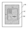
図17はイメージスキャナ21の読取可能範囲70と印刷画像16の関係を説明する図である。イメージスキャナ21は、ユーザから印刷画像16の読み取りを指示されると、付加情報の埋込領域53を有する印刷媒体51の全面を含む、読取可能範囲70で画像を光学的に読み取り、画像情報D4をブロック位置検出部62に出力する。
FIG. 17 is a diagram for explaining the relationship between the
ブロック位置検出部62は、画像情報D4に多重化された付加情報が埋め込まれた各ブロックの正確な位置を検出する。詳細は後述するが、画像情報D4に対して、一画素および複数画素ずつ位置をずらしながら、付加情報Xの分離に使用するブロック単位のテクスチャの周波数特性を解析して算出した周波数特性量を用いて、ブロックの位置を検出する。あるいは、付加情報Xの符号判定を行う際の符号判定量を用いて、ブロックの位置を検出する。そして、ブロック位置検出部62は、画像情報D4と、検出したブロックの位置を示すブロック位置情報を含む画像情報D5を付加情報分離部63に出力する。
The block
付加情報分離部63は、画像情報D5からブロック位置情報を取り出し、一つまたは複数のブロックの位置に対して、ブロック単位にテクスチャの周波数解析を行う。そして、各ブロックに埋め込まれたブロック単位の符号を判定して、付加情報Yを復元し、付加情報Yを出力端子64に出力する。なお、付加情報の分離方法には公知の方法を用いる。
The additional
●付加情報抽出処理
ブロック位置検出部62が検出したブロックの数が、付加装置が付加情報Xを埋め込んだブロックの数と異なれば、画像情報D5から付加情報Yを分離したとしても、復元した付加情報Yは、付加装置が埋め込んだ付加情報Xと異なる。
Additional information extraction processing If the number of blocks detected by the block
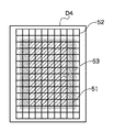
図18はブロック位置検出部62が検出したブロックの数が、付加装置が付加情報Xを埋め込んだブロックの数と異なる例を示す図である。図18は、イメージスキャナ21の読取可能範囲70が印刷媒体51のサイズよりも大きいと仮定している。つまり、画像情報D4の画像サイズは印刷媒体51のサイズよりも大きい。ブロック位置検出部62は、画像領域D4の全域に埋め込める最大数のブロック位置を検出したとすると、ブロック位置情報は符合52で示すようになる。従って、ブロック位置情報52が示すブロックの数と、付加情報Xが埋め込まれているブロックの数は異なることになる。
FIG. 18 is a diagram illustrating an example in which the number of blocks detected by the block
ブロック位置検出部62が検出したブロックの数と、付加情報Xが埋め込まれたブロックの数が異なる場合、ブロック位置情報に基づき付加情報Yを分離した後、分離した付加情報Yから付加情報Xを抽出する付加情報抽出処理が必要になる。
When the number of blocks detected by the block
付加情報Yから付加情報Xを抽出する付加情報抽出処理は、様々な方法が考えられる。 Various methods can be considered for the additional information extraction processing for extracting the additional information X from the additional information Y.
例えば、付加情報Yを分離する際にブロック単位にテクスチャの周波数解析を行うが、その解析結果の周波数特性量を利用する方法がある。付加情報が埋め込まれた個所と埋め込まれていない個所で周波数特性量が異なる場合、周波数特性値に対して特徴抽出を行い、付加装置が埋め込んだ付加情報Xのブロック位置を検出することができる。 For example, when separating the additional information Y, texture frequency analysis is performed in units of blocks, and there is a method of using the frequency characteristic amount of the analysis result. When the frequency characteristic amount is different between the location where the additional information is embedded and the location where the additional information is not embedded, feature extraction is performed on the frequency characteristic value, and the block position of the additional information X embedded by the additional device can be detected.
また、付加情報Yを分離する際に、ブロック単位にテクスチャの周波数解析を行い、ブロック単位の符号判定を行うが、符号判定に用いる符号判定量を利用する方法がある。付加情報が埋め込まれた個所と埋め込まれていない個所で符号判定量が異なる場合、符号判定量に対して特徴抽出を行い、付加装置が埋め込んだ付加情報Xのブロック位置を検出することができる。 Further, when separating the additional information Y, texture frequency analysis is performed for each block and code determination is performed for each block. There is a method of using a code determination amount used for code determination. When the code determination amount is different between the portion where the additional information is embedded and the portion where it is not embedded, feature extraction is performed on the code determination amount, and the block position of the additional information X embedded by the additional device can be detected.
また、前述したように、付加装置が埋め込んだ付加情報に、付加情報の位置を示すマーカが埋め込まれていれば、付加情報Yを分離した後、付加情報Yからマーカを検出して、付加装置が埋め込んだ付加情報Xのブロック位置を検出することができる。 Further, as described above, if a marker indicating the position of the additional information is embedded in the additional information embedded by the additional device, after the additional information Y is separated, the marker is detected from the additional information Y, and the additional device is detected. The block position of the additional information X embedded in can be detected.
●方向判定処理
イメージスキャナ21によって、印刷画像16を任意の方向から読み取って付加情報を抽出する場合、印刷画像16の読取方向を判定する方向判定処理が必要になる。
Direction Determination Process When the
方向判定処理は、ブロック位置検出部62が出力したブロック位置情報に対してブロック単位の符号判定を行って分離した付加情報Yから、埋め込まれた付加情報Xの向きを判定する。分離した付加情報Yから付加情報Xの向きを判定する方法は、様々な方法が考えられる。
In the direction determination process, the direction of the embedded additional information X is determined from the additional information Y obtained by performing block-unit code determination on the block position information output from the block
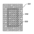
例えば、付加情報の位置を示すマーカから付加情報の向きを判定する方法がある。図19はイメージスキャナ21が読み取った画像の向きが付加情報Xの向きと一致する場合の、付加情報Yの分離結果を示す図である。一方、図20はイメージスキャナ21が読み取った画像の向きと、付加情報Xの向きが上下反転している場合の、付加情報Yの分離結果を示す図である。
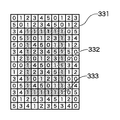
For example, there is a method for determining the direction of the additional information from a marker indicating the position of the additional information. FIG. 19 is a diagram illustrating a separation result of the additional information Y when the orientation of the image read by the
図19と20は、図18のように、ブロック位置検出部62が検出したブロックの数が、付加装置が付加情報Xを埋め込んだブロックの数と異なる場合を示している。また、図19と20に示す各ブロックの値は、ブロック位置検出部62が検出した横10×縦14(合計140個)のブロック集合331に対して、付加情報分離部63が分離した付加情報Yの値を示している。ブロック集合331に含まれる、ブロック集合332には付加情報Xが埋め込まれている。また、ブロック集合331に含まれる、ブロック集合333はマーカである。
FIGS. 19 and 20 show a case where the number of blocks detected by the block
付加装置がマーカとして‘1’を埋め込むとする。また、上述したように、ブロックの符号パターンは、回転させても回転前の符号パターンの何れかになる符号パターンであり、上下反転した場合、‘1’が‘4’になる規則性をもつとする。この場合、イメージスキャナ21が読み取った画像の向きと、付加情報Xの向きが一致すれば、付加情報Xのブロック集合332の周囲にはマーカ‘1’が埋め込まれたブロック集合333が検出される。また、イメージスキャナ21が読み取った画像の向きと、付加情報Xの向きが上下反転していれば、付加情報Xのブロック集合332の周囲にはマーカ‘4’が埋め込まれたブロック集合333が検出される。
Assume that the additional device embeds “1” as a marker. In addition, as described above, the code pattern of the block is a code pattern that becomes one of the code patterns before rotation even when rotated, and has a regularity that '1' becomes '4' when flipped upside down. And In this case, if the orientation of the image read by the
従って、ブロック集合333に埋め込まれたマーカの値を復元して、‘1’であればイメージスキャナ21が読み取った画像の向きは付加情報Xの向きと一致すると判定する。また、マーカの値が‘4’であればイメージスキャナ21が読み込んだ画像の向きと、付加情報Xの向きは上下反転していると判定する。画像情報D4の向きと付加情報Xの向きの関係に基づき、画像情報D4から分離した符号パターンを、画像情報D4の向きと付加情報Xの向きが一致する場合の符号パターンに変換することで、付加情報Xを正しく復元することが可能になる。
Therefore, the value of the marker embedded in the block set 333 is restored, and if it is “1”, it is determined that the orientation of the image read by the
また、付加情報Xの向きを判定するために、付加情報の埋込領域の四隅にマーカを埋め込む方法、付加情報Xのデータ列を所定間隔に区切ったデータ列の間に方向判定用のデータ列を挿入する方法、付加情報Xの先頭と末尾に所定の符号を挿入する方法などがある。付加情報Xの位置や回転方向を示すマーカを埋め込み、埋め込んた方式や規則性などに基づきマーカを検出することができれば、付加情報Xの向きを判定することができる。言い換えれば、付加情報Xの位置や向きを示す何らか情報を埋め込めば、方向判定処理によって、付加情報Xの向きを検出することができる。 Further, in order to determine the direction of the additional information X, a method of embedding markers at the four corners of the additional information embedding area, a data string for direction determination between the data strings obtained by dividing the data string of the additional information X at a predetermined interval And a method of inserting a predetermined code at the beginning and end of the additional information X. If the marker indicating the position and rotation direction of the additional information X is embedded and the marker can be detected based on the embedded method or regularity, the direction of the additional information X can be determined. In other words, if any information indicating the position or direction of the additional information X is embedded, the direction of the additional information X can be detected by the direction determination process.
[付加情報の抽出処理]
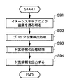
図21は抽出装置の付加情報の抽出手順を示すフローチャートである。
[Extraction processing of additional information]
FIG. 21 is a flowchart showing a procedure for extracting additional information by the extracting device.
まず、イメージスキャナ21により印刷画像16を光学的に読み取って画像情報D4を生成する(S91)。次に、ブロック位置検出部62により画像情報D4からブロック位置を検出する(S92)。ブロック位置を示すブロック位置情報は、画像情報D4とともに、画像情報D5として付加情報分離部63に入力される。次に、付加情報分離部63によりブロック位置情報に基づき、各ブロックのテクスチャの周波数特性を解析して、付加情報Yを分離する(S93)。そして、必要ならば付加情報分離部63により、付加情報Yから付加情報Xを復元して、分離した付加情報Yまたは復元した付加情報Xを出力端子64から出力する(S94)。
First, the
[ブロック位置検出部]
図22はブロック位置検出部62の詳細な構成例を示すブロック図である。
[Block position detector]
FIG. 22 is a block diagram showing a detailed configuration example of the block
位置検出部162は、画像情報D4と検出領域情報A1を入力し、検出領域情報A1で設定される領域に対しブロック位置を検出して、ブロック位置情報B1を出力する。
The
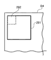
図23は位置検出部162の動作を説明する図である。
FIG. 23 is a diagram for explaining the operation of the
例えば、検出領域情報A1が画像情報D4上の検出領域291を示す場合、位置検出部162は、検出領域291においてブロックの検出を行う。位置検出部162は、検出領域291内において所定サイズのブロック292の位置を画素単位にずらし、ブロック292のテクスチャの周波数解析と、付加情報を分離する付加情報分離処理を行う。そして、周波数解析結果の周波数特性値と付加情報を分離する際の付加情報判定値を算出して、ブロック位置を検出する。つまり、周波数特性値と付加情報判定値は、付加情報が埋め込まれたブロックの値と埋め込まれていないブロックの値が異なることを利用して、ブロック位置を検出する。
For example, when the detection area information A1 indicates the
検出位置保存部163は、ブロック位置情報B1をメモリ(例えばRAM 24)に格納し、ブロック位置の検出処理を継続するか否かを判断する。そして、ブロック位置の検出処理を継続すると判断した場合は、必要ならば検出領域情報A1を再設定し、位置検出部162に処理の継続を指示する。そして、位置検出部162から出力されるブロック位置情報B1によって、メモリに格納したブロック位置情報B1を更新する。検出位置保存部163は、ブロック位置の検出処理を継続しないと判断した場合は、メモリに格納した一つまたは複数のブロック位置情報をブロック位置情報B2として出力する。
The detection
ブロック位置情報出力部164は、詳細は後述するが、ブロック位置情報B2からブロック位置情報B3を計算して、画像情報D4とともに、画像情報D5として出力する。
The block position
図24はブロック位置検出部62の処理を説明するフローチャートである。
FIG. 24 is a flowchart for explaining the processing of the block
まず、検出領域情報A1を設定する(S101)。そして、位置検出部162に画像情報D4と検出領域情報A1を入力し、ブロック位置検出処理を実行する(S102)。次に、位置保存部163によりブロック位置情報B1をメモリに格納(検出ブロック保存処理)する(S103)。そして、メモリに格納したブロック位置情報B1と検出領域情報A1の関係から、ブロック位置検出処理(S102)を継続するか否かを判定する(S104)。ブロック位置検出処理を継続すると判定した場合は、処理をステップS101に戻して、必要ならば検出領域情報A1を再設定する。また、ブロック位置検出処理を継続しないと判定した場合は、メモリに格納したブロック位置情報B2を出力する(S105)。
First, detection area information A1 is set (S101). Then, the image information D4 and the detection area information A1 are input to the
●ブロック位置検出処理の詳細
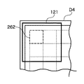
図25はイメージスキャナ21から出力された画像情報D4の領域内に検出領域121〜126が配置された様子を示す図である。なお、検出領域の大きさ、位置、数に関して、特に限定はない。また、検出領域は予め設定されていてもよいし、画像情報D4に従って設定してもよい。また、一旦、一つのブロックのブロック位置情報B1を生成した後、次の検出領域を設定してもよい。また、画像情報D4の領域を四分割して、それら四領域を検出領域にすることもできる。あるいは、検出領域情報A1として検出領域の間隔(幅と高さ)を設定して、当該間隔に従い順次、検出領域を設定しても構わない。
Details of Block Position Detection Processing FIG. 25 is a diagram showing a state where the
図26はブロック位置検出処理(S102)の詳細な処理手順を示すフローチャートである。 FIG. 26 is a flowchart showing a detailed processing procedure of the block position detection process (S102).
まず、付加情報を分離する際の基準になるブロック開始位置を設定する(S111)。次に、ブロック開始位置から処理ブロック262単位にテクスチャの周波数解析を行って周波数特性量を算出し、周波数特性量から処理ブロック262単位の符号判定を行い符号判定量を算出する(S112)。次に、算出した周波数特性量と符号判定量をメモリに順次格納し(S113)、検出領域単位のブロック位置検出処理が終了したか否かを判定する(S114)。検出領域単位のブロック位置検出処理が未了の場合は処理をステップS111に戻し、終了した場合は、メモリに格納した周波数特性量と符号判定量から、検出領域内のブロック位置を算出してブロック位置情報B1を出力する(S115)。
First, a block start position serving as a reference for separating additional information is set (S111). Next, the frequency characteristic of the texture is calculated for each processing block 262 from the block start position to calculate the frequency characteristic amount, and the code determination for the
検出領域として、例えば100×100画素の領域が設定されているとする。ブロック開始位置の設定(S111)では、検出領域の10000画素から一画素を選択して、選択した画素の位置をブロック開始位置として設定する。 For example, it is assumed that an area of 100 × 100 pixels is set as the detection area. In setting the block start position (S111), one pixel is selected from 10,000 pixels in the detection area, and the position of the selected pixel is set as the block start position.
周波数特性量と符号判定量の計算(S112)では、ブロック開始位置から、処理ブロック262単位にテクスチャの周波数解析を行って周波数特性量を計算し、周波数特性量から処理ブロック262単位に符号判定量を計算する。そして、周波数特性量と符号判定量は、付加情報が埋め込まれているブロックと、埋め込まれていないブロックで異なることを利用してブロック位置を算出する。
In the calculation of the frequency characteristic amount and the code determination amount (S112), the frequency characteristic amount is calculated by performing texture frequency analysis for each processing block 262 from the block start position, and the code determination amount is calculated from the frequency characteristic amount for each
図27はブロック位置検出処理において、処理ブロック262の位置と、付加情報が埋め込まれたブロックの位置が一致していない状態を示す図である。図28はブロック位置検処理において、処理ブロック262の位置と、付加情報が埋め込まれたブロックの位置が一致している状態を示す図である。図27に示すように、処理ブロック262の位置と、付加情報が埋め込まれたブロックの位置と一致していない状態で周波数特性量と符号判定量の計算(S112)を行うと、例えば符号判定量が10になる。一方、図28に示すように、処理ブロック262の位置と、付加除法が埋め込まれたブロックの位置が一致している状態で周波数特性量と符号判定量の計算(S112)を行うと、例えば符号判定量は50になる。
FIG. 27 is a diagram illustrating a state in which the position of the
周波数特性量と符号判定量のメモリ格納(S113)では、ステップS112で算出した周波数特性量と符号判定量をメモリに格納する。ただし、周波数特性量または符号判定量だけをメモリに格納しても構わない。 In storing the frequency characteristic amount and the code determination amount in the memory (S113), the frequency characteristic amount and the code determination amount calculated in step S112 are stored in the memory. However, only the frequency characteristic amount or the code determination amount may be stored in the memory.
検出領域分の処理の終了判定(S114)では、この例では100×100画素の検出領域内のブロック位置検出処理が終了したか否かを判定する。なお、また、検出領域内の処理ブロック262の移動量は、一画素に限定されず、二画素でもよいし、ランダムでもよい。また、千鳥格子状に処理ブロック262を移動しても構わない。
In the process end determination for the detection area (S114), in this example, it is determined whether or not the block position detection process in the detection area of 100 × 100 pixels is ended. In addition, the movement amount of the
ブロック位置情報B1の出力(S115)では、メモリに格納した例えば10000画素分の符号判定量からブロック位置を算出する。 In the output (S115) of the block position information B1, the block position is calculated from the code determination amount for, for example, 10,000 pixels stored in the memory.
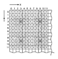
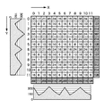
図29はブロック位置の算出を説明する図で、各升の値は、処理ブロック262を一画素ずつずらして算出した符号判定量の一例を示している。
FIG. 29 is a diagram for explaining the calculation of the block position, and the value of each wrinkle shows an example of the code determination amount calculated by shifting the
例えば、算出した符号判定量が大きい方が付加情報が埋め込まれたブロックの位置に一致している可能性が高いという規則性がある。これを利用すれば、算出した符号判定量の中で、周囲に比べて大きな値の符号判定量を得たときの処理ブロック262の位置を検出して、ブロック位置を算出することができる。例えば、図29において、(x, y)=(3, 3)の符号判定量「60」、(9,3)の「56」、(3, 9)の「45」、(9, 9)の「38」は周囲に比べて大きな符号量を示す。従って、これら位置の符号判定量を得たときの処理ブロック262の位置が、ブロック位置に相当することになる。なお、符号判定量が大きい方が付加情報が埋め込まれたブロック位置に一致している可能性が高いと説明した。しかし、付加情報の埋込方法によっては、符号判定量が小さい方が付加情報が埋め込まれたブロック位置に一致している可能性が高い場合もあり、どちらを採用しても構わない。
For example, there is a regularity that the larger the code determination amount is, the higher the possibility that it matches the position of the block in which the additional information is embedded. By utilizing this, the position of the
図30は、図29の各升の符号判定量をX軸方向とY軸方向で加算した結果を示す図である。図30に示す加算結果から、付加情報が埋め込まれたブロック位置に対応する処理ブロック262のX、Y座標を算出する方法もある。図30には、加算結果をグラフ304、305にして表すが、グラフのピーク位置が、付加情報が埋め込まれたブロック位置に対応する処理ブロック262のX、Y座標に対応する。また、ピーク位置の間隔から付加情報が埋め込まれたブロックのサイズが6×6画素であることがわかる。
FIG. 30 is a diagram illustrating a result of adding the code determination amount of each bag in FIG. 29 in the X-axis direction and the Y-axis direction. There is also a method of calculating the X and Y coordinates of the
また、付加情報が埋め込まれたブロックのサイズが予測できる場合は、ブロック単位に符号判定量を加算した結果からブロック位置を算出する方法も考えられる。例えば、ブロックサイズが6×6画素であることが予測できれば、6×6画素ブロック分の符号判定量301の加算を行う。具体的には、左上の座標(0, 0)を基準として、(0, 0)(6, 0)(0, 6)(6, 6)の位置の符号判定量を加算する。図29に示す例では加算値は8である。また、X方向に一画素ずらした6×6画素ブロックの加算値は、(1, 0)(7, 0)(1, 6)(7, 6)の符号判定量の合計であるから12である。この作業を6×6画素ブロック分繰り返す。図31は6×6画素ブロックを想定した場合に、図29に示す符号判定量を6×6画素ブロック単位に加算した結果を示す図である。図31に示すように、符号判定量の合計の最大値は(3, 3)の199であり、(3, 3)の処理ブロック262に対応する位置から6×6画素単位に、付加情報が埋め込まれたブロックが並んでいることがわかる。
In addition, when the size of the block in which the additional information is embedded can be predicted, a method of calculating the block position from the result of adding the code determination amount for each block may be considered. For example, if the block size can be predicted to be 6 × 6 pixels, the code determination amount 301 for 6 × 6 pixel blocks is added. Specifically, the code determination amount at the position (0, 0) (6, 0) (0, 6) (6, 6) is added with the upper left coordinate (0, 0) as a reference. In the example shown in FIG. 29, the added value is 8. In addition, the added value of the 6 × 6 pixel block shifted by one pixel in the X direction is 12 because it is the sum of the code determination amounts of (1, 0) (7, 0) (1, 6) (7, 6). is there. This operation is repeated for 6 × 6 pixel blocks. FIG. 31 is a diagram illustrating a result of adding the code determination amount illustrated in FIG. 29 in units of 6 × 6 pixel blocks assuming a 6 × 6 pixel block. As shown in FIG. 31, the maximum value of the code determination amount is 199 of (3, 3), and the additional information is in units of 6 × 6 pixels from the position corresponding to the
このように、画素単位、所定数の画素単位、ブロック単位またはライン単位に符号判定量を加算した値からピーク値(またはボトム値)を求めてブロック位置を算出することができる。また、画素単位、所定数の画素単位、ブロック単位またはライン単位にフィルタ係数を掛けてピーク値(またはボトム値)を求めブロック位置を算出してもよい。勿論、符号判定量ではなく、周波数特性量からブロック位置を算出してもよい。 In this way, the block position can be calculated by obtaining the peak value (or bottom value) from the value obtained by adding the code determination amount to the pixel unit, the predetermined number of pixel units, the block unit, or the line unit. Alternatively, the block position may be calculated by obtaining a peak value (or a bottom value) by multiplying a pixel unit, a predetermined number of pixel units, a block unit, or a line unit by a filter coefficient. Of course, the block position may be calculated from the frequency characteristic amount instead of the code determination amount.
●検出ブロック保存処理の詳細
検出ブロック保存処理(S103)では、ブロック位置検出処理S102で出力されるブロック位置情報B1を順次メモリに格納する。例えば、図25に示す六つの検出領域121〜126が設定された場合、各検出領域のブロック位置情報B1をメモリに格納する。
Details of Detection Block Saving Process In the detection block saving process (S103), the block position information B1 output in the block position detection process S102 is sequentially stored in the memory. For example, when the six
●ブロック位置検出処理の終了判定の詳細
ブロック位置検出処理の終了判定(S104)では、検出領域情報A1によって設定される複数の検出領域におけるブロック位置検出処理(S102)が終了したか否かを判定する。例えば、図12に示すように、検出領域情報A1によって六つの検出領域121〜126が設定されている場合は、検出領域121〜126におけるブロック位置検出処理が行われたか否かを判定する。そして、ブロック位置検出処理を継続する場合、言い換えれば、ブロック位置検出処理が未了の検出領域がある場合は、処理をブロック位置検出処理(S102)に戻す。また、ブロック位置検出処理を継続しない場合は、メモリに格納されたブロック情報B1をブロック情報B2として出力する。なお、入力される画像情報D4から検出領域を設定し、ブロック位置検出部162の処理が終了しているか否かを判定して、ブロック位置検出処理の継続を判断してもよい。また、ブロック位置情報B1からブロック位置検出処理の継続を判断してもよい。
Details of block position detection process end determination In block position detection process end determination (S104), it is determined whether block position detection processing (S102) in multiple detection areas set by detection area information A1 has ended. To do. For example, as shown in FIG. 12, when the six
例えば、図25に示す画像情報D4の画像サイズが1000×1200画素で、検出領域情報A1に開始点情報(0, 0)と検出領域のサイズ500×500画素が設定されているとする。この場合、画像情報D4のサイズを逸脱しないように検出領域を設定すると、検出領域121〜124の対角頂点は次のようになる。
検出領域121 … (0, 0)(500, 500)、
検出領域122 … (500, 0)(1000, 500)、
検出領域123 … (0, 500)(500, 1000)、
検出領域124 … (500, 500)(1000, 1000)
For example, it is assumed that the image size of the image information D4 shown in FIG. 25 is 1000 × 1200 pixels, and the start point information (0, 0) and the detection region size 500 × 500 pixels are set in the detection region information A1. In this case, if the detection area is set so as not to deviate from the size of the image information D4, the diagonal vertices of the
そして、検出領域125と126は、検出領域情報A1に設定された検出領域のサイズ500×500画素では、画像領域D4を逸脱するので、検出領域125と126におけるブロック位置検出処理を行わず処理を終了することもできる。また、検出領域125と126は、画像情報D4のサイズに合わせて、検出領域125と126の対角頂点をそれぞれ(0, 1000)(500, 1200)、(500, 1000)(1200, 1200)としてもよい。つまり、検出領域のサイズを500×200画素に設定し直し、検出領域125と126におけるブロック位置検出処理を行って処理を終了することもできる。
Since the
●ブロック位置情報の出力処理の詳細
ブロック位置情報の出力処理(S105)において、ブロック位置情報B2から、画像情報D4全体に対するブロック位置情報B3を算出する。そして、算出したブロック位置情報B3と画像情報D4を含む画像情報D5を出力する。
Details of Block Position Information Output Processing In block position information output processing (S105), block position information B3 for the entire image information D4 is calculated from block position information B2. Then, image information D5 including the calculated block position information B3 and image information D4 is output.
図32は画像情報D4とブロック位置情報B2の関係を示す図である。 FIG. 32 is a diagram showing the relationship between the image information D4 and the block position information B2.
図32において、画像情報D4内で検出したブロック位置情報B2は●(黒丸)161、162で示される。ブロック位置情報161、162などからブロック位置情報B3を算出するには、予め設定されたN×N画素のブロックサイズを利用して、公知の内分点算出、外分点算出の公式を用いて行う。
In FIG. 32, block position information B2 detected in the image information D4 is indicated by ● (black circles) 161 and 162. In order to calculate the block position information B3 from the
例えば、N×N画素のブロックサイズが200×200画素にする場合、ブロック位置情報161の座標は(300, 100)、ブロック位置情報162の座標は(704, 100)だとする。この場合、ブロック位置情報161と162のX方向の間隔は704-300=404画素である。N×N画素のブロックサイズ200×200画素に基づき、間隔404画素を200画素で割ると2.02が得られる。従って、ブロック位置情報161と162のX方向の間に二つのブロックがあると推測することができる。
For example, when the block size of N × N pixels is 200 × 200 pixels, the coordinates of the
次に、ブロック位置情報161と162の内分点を計算して座標(502, 100)にブロックがあるとする。また、ブロック位置情報161と162の外分点を計算して座標(98, 100)にブロックがあるとする。このように、ブロック位置情報B2から内分点と外分点を計算することで、画像情報D4に存在するブロック位置を示すブロック位置情報B3を算出することができる。
Next, it is assumed that an internal dividing point between the
図33は算出したブロック位置情報B3を画像情報D4にプロットした様子を示す図である。破線の交点がブロック位置情報B3が示すブロック位置であり、破線に囲まれた領域がN×N画素のブロックである。 FIG. 33 is a diagram illustrating a state where the calculated block position information B3 is plotted on the image information D4. The intersection of the broken lines is the block position indicated by the block position information B3, and the area surrounded by the broken lines is an N × N pixel block.
このように、画像を分割したブロックごとに付加情報が埋め込まれている画像において、図3に符号233で示すような付加情報の埋込範囲を示す基準マークがなくても、付加情報が埋め込まれたブロック位置を高精度に検出して付加情報を抽出することができる。
In this way, in the image in which the additional information is embedded for each block obtained by dividing the image, the additional information is embedded even if there is no reference mark indicating the embedded range of the additional information as indicated by
また、付加情報の埋込範囲が画像サイズに依存しない場合でも、付加情報が埋め込まれたブロック位置が検出することができる。従って、縁なし印刷のように、印刷しようとする画像を印刷媒体より大きなサイズにして、画像の縁が切り取られる形態で印刷する場合がある。この場合も、印刷媒体のサイズ内に付加情報が埋め込まれていれば、付加情報が埋め込まれたブロック位置を高精度に検出して付加情報を抽出することができる。 Even when the embedded range of the additional information does not depend on the image size, the block position where the additional information is embedded can be detected. Therefore, as in borderless printing, an image to be printed may be printed in a size that is larger than the print medium and the edges of the image are cut off. Also in this case, if the additional information is embedded within the size of the print medium, the additional information can be extracted by detecting the block position where the additional information is embedded with high accuracy.
以下、本発明にかかる実施例2の画像処理を説明する。なお、実施例2において、実施例1と略同様の構成については、同一符号を付して、その詳細説明を省略する。 The image processing according to the second embodiment of the present invention will be described below. Note that the same reference numerals in the second embodiment denote the same parts as in the first embodiment, and a detailed description thereof will be omitted.
[概要]
実施例1の付加情報多重化部14は、入力される画像情報D1のある領域をN×N画素の複数のブロックに分割し、ブロックごとに誤差拡散法の量子化閾値を付加情報のビットに応じて変化させる。そして、ブロックの符号パターンをサブブロックの組み合わせで構成し、各サブブロックのパターンを回転対称とし、上下反転した符号パターンが、上下反転前の符号パターンの何れかになるようなパターンの組み合わせにする。しかし、ブロックの符号パターンをサブブロックの組み合わせで構成しただけでは、付加情報が埋め込まれた正しいブロック位置を検出することができないことがある。
[Overview]
The additional
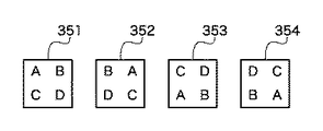
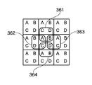
図34は付加情報を埋め込むブロックを構成する四つ符号パターンを示す図である。符号パターン351〜354は、四つのサブブロックの組み合わせで構成され、サブブロックの各パターンをA、B、C、Dとする。図35は符号パターン351を連続して埋め込んだ様子を示す図である。
FIG. 34 is a diagram showing four code patterns constituting a block in which additional information is embedded. The
ブロック位置検出部62は、ブロックのテクスチャの周波数解析と、付加情報を分離する付加情報分離処理を行い、周波数解析結果の周波数特性値と付加情報を分離する際の符号判定値を算出する。そして、周波数特性値と符号判定値から特徴抽出を行い、ブロック位置を検出する。その際、周波数特性値と符号判定値は、処理ブロックの位置と、付加情報が埋め込まれたブロックの位置が一致する場合と、ずれている場合で、値が異なることを利用する。
The block
しかし、ブロック位置検出部62は、図35に示す検出領域361、364でブロック位置を検出すると、当該領域の符号パターンが図34に示す符号パターン353と一致するため、付加情報が埋め込まれたブロック位置と判断してしまう。同様に、図35に示す検出領域362、363でブロック位置を検出すると、当該領域の符号パターンが図34に示す符号パターン352と一致するため、付加情報が埋め込まれたブロック位置と判断してしまう。その結果、サブブロック一つ分ずれた位置に、付加情報が埋め込まれたブロックがあると判断して、付加情報が埋め込まれたブロック位置を正しく検出することができない。
However, when the block
図36はサブブロック一つ分ずれた位置に付加情報が埋め込まれたブロックがあると判断した場合に、処理ブロックを一画素ずつずらしながら算出した符号判定量と、その加算値を示す図である。 FIG. 36 is a diagram illustrating a code determination amount calculated by shifting the processing block by one pixel and an addition value when it is determined that there is a block in which additional information is embedded at a position shifted by one subblock. .
付加情報が埋め込まれたブロックが6×6画素、そのサブブロックが3×3画素とすると、付加情報が埋め込まれたブロック位置を正しく検出することができれば、六画素ごとにX方向の加算値とY方向の加算値にピークが現れる。従って、6画素毎に横軸、縦軸の最大値になるような個所を検出できればよいことになる。しかし、図36に示す例では、三画素間隔で加算値にピークが現れる If the block where the additional information is embedded is 6 × 6 pixels and the sub-block is 3 × 3 pixels, if the block position where the additional information is embedded can be detected correctly, the addition value in the X direction will be A peak appears in the added value in the Y direction. Therefore, it is only necessary to detect a location where the horizontal axis and the vertical axis become maximum values every 6 pixels. However, in the example shown in FIG. 36, a peak appears in the added value at intervals of three pixels.
図36に示すような符号判定値からは、付加情報が埋め込まれたブロック位置を正しく検出することができない。実施例2は、このような問題を解決するためのものである。 From the code determination value as shown in FIG. 36, the block position in which the additional information is embedded cannot be detected correctly. Example 2 is for solving such a problem.
[サブブロックのパターンの組み合わせ方法]
以下では、上記の問題を解決して、付加情報が埋め込まれたブロック位置を正しく検出するための、符号パターンを設定する際のサブブロックのパターンの組み合わせ方法について説明する。
[Combination method of sub-block patterns]
Hereinafter, a method of combining sub-block patterns when setting a code pattern for solving the above-described problem and correctly detecting a block position in which additional information is embedded will be described.
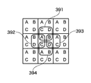
図37は付加情報を埋め込むブロックを構成する四つ符号パターンを示す図である。符号パターン381〜384は、四つのサブブロックの組み合わせで構成され、サブブロックの各パターンをA、B、C、Dとする。図38は符号パターン381を連続して埋め込んだ様子を示す図である。
FIG. 37 is a diagram showing four code patterns constituting a block in which additional information is embedded. The
ブロック位置検出部62は、図38に示す検出領域391、394でブロック位置を検出すると、当該領域の符号パターンは図37に示す何れの符号パターンとも一致しないため、付加情報が埋め込まれたブロック位置ではないと判断することができる。同様に、図38に示す検出領域392、393でブロック位置を検出すると、当該領域の符号パターンが図37に示す何れの符号パターンとも一致しないため、付加情報が埋め込まれたブロック位置ではないと判断することができる。このように、ブロックの符号パターン同士が、どのような組み合わせで隣接されたとしても、サブブロック一つ分ずれた位置では、付加情報が埋め込まれたブロック位置ではないと判断可能なサブブロックのパターンの組み合わせを符号パターンに設定すればよい。
When the block
図37に示す符号パターン381〜384は、異なるサブブロックのパターンA、B、C、Dの四つを組み合わせて一つの符号パターンにする例である。符号パターン381〜384は、上下反転しても、符号パターン381〜384の何れかの符号パターンになる。さらに、符号パターン381〜384は、ブロックの符号パターン同士が、どのような組み合わせで隣接していても、サブブロック一つ分ずれた位置では、付加情報が埋め込まれたブロック位置ではないと判断可能である。
符号パターンのサブブロックの組み合わせの数は、符号パターンの数やサブブロックの数によって変化する。従って、図37の符号パターン381〜384に限定されるわけではない。つまり、上下反転しても設定した何れかの符号パターンになり、ブロックの符号パターン同士がどのような組み合わせで隣接しても、サブブロック一つ分ずれた位置で、付加情報が埋め込まれたブロック位置ではないと判断可能な符号パターンであればよい。
The number of combinations of code pattern sub-blocks varies depending on the number of code patterns and the number of sub-blocks. Therefore, it is not limited to the
このように、付加情報多重化部14の符号パターンを構成するサブブロックのパターンの組み合わせを適切に設定することで、付加情報が埋め込まれたブロック位置を正しく検出することができる。
In this way, by appropriately setting the combination of sub-block patterns constituting the code pattern of the additional
[他の実施例]
なお、本発明は、複数の機器(例えばコンピュータ、インタフェイス機器、リーダ、プリンタなど)から構成されるシステムに適用しても、一つの機器からなる装置(例えば、複写機、ファクシミリ装置、制御装置など)に適用してもよい。
[Other embodiments]
Note that the present invention can be applied to a system composed of a plurality of devices (for example, a computer, an interface device, a reader, a printer, etc.), or a device (for example, a copier, a facsimile machine, a control device) composed of a single device. Etc.).
また、本発明の目的は、上記実施例の機能を実現するコンピュータプログラムを記録した記憶媒体をシステムまたは装置に供給し、そのシステムまたは装置のコンピュータ(CPUやMPU)が前記コンピュータプログラムを実行することでも達成される。この場合、記憶媒体から読み出されたソフトウェア自体が上記実施例の機能を実現することになり、そのコンピュータプログラムと、そのコンピュータプログラムを記憶する記憶媒体は本発明を構成する。 Another object of the present invention is to supply a storage medium storing a computer program for realizing the functions of the above-described embodiments to a system or apparatus, and the computer (CPU or MPU) of the system or apparatus executes the computer program. But it is achieved. In this case, the software itself read from the storage medium realizes the functions of the above-described embodiments, and the computer program and the storage medium storing the computer program constitute the present invention.
また、前記コンピュータプログラムの実行により上記機能が実現されるだけではない。つまり、そのコンピュータプログラムの指示により、コンピュータ上で稼働するオペレーティングシステム(OS)などが実際の処理の一部または全部を行い、それによって上記機能が実現される場合も含む。 Further, the above functions are not only realized by the execution of the computer program. That is, it includes a case where an operating system (OS) or the like running on the computer performs part or all of the actual processing according to an instruction of the computer program, thereby realizing the above functions.
また、前記コンピュータプログラムがコンピュータに接続された機能拡張カードやユニットのメモリに書き込まれていてもよい。つまり、そのコンピュータプログラムの指示により、前記カードやユニットのCPUなどが実際の処理の一部または全部を行い、それによって上記機能が実現される場合も含む。 The computer program may be written in a function expansion card connected to the computer or a memory of the unit. That is, the case where the above functions are realized by the CPU or the CPU of the unit performing part or all of the actual processing in accordance with the instruction of the computer program.
本発明を前記記憶媒体に適用する場合、その記憶媒体には、先に説明したフローチャートに対応または関連するコンピュータプログラムが格納される。 When the present invention is applied to the storage medium, the storage medium stores a computer program corresponding to or related to the flowchart described above.
Claims (10)
前記画像情報を疑似中間調処理する中間調処理手段と、
前記付加情報に応じて前記疑似中間調処理の量子化閾値を制御して、量子化された複数画素で構成される複数の符号パターンを形成することで、前記疑似中間調処理された画像情報に前記付加情報を埋め込む埋込手段とを有し、
前記付加情報は、前記画像情報が表す画像上の、前記付加情報が埋め込まれた位置を検出するための位置検出情報、および、前記画像情報が表す画像の向きと、前記付加情報を埋め込んだ向きとの関係を検出するための方向判定情報を含み、
前記符号パターンを回転した場合、回転後の符号パターンは、回転前の前記複数の符号パターンの何れかに一致することを特徴とする画像処理装置。 An image processing apparatus for embedding additional information in image information,
Halftone processing means for performing pseudo-halftone processing on the image information;
By controlling the quantization threshold value of the pseudo halftone process according to the additional information and forming a plurality of code patterns composed of a plurality of quantized pixels, the pseudo halftone process image information is formed. Embedding means for embedding the additional information,
The additional information includes position detection information for detecting a position where the additional information is embedded on an image represented by the image information , a direction of the image represented by the image information , and a direction in which the additional information is embedded. viewing including the direction determination information for detecting the relationship between,
When the code pattern is rotated, the code pattern after rotation matches any of the plurality of code patterns before rotation .
前記画像情報を疑似中間調処理する中間調処理手段と、
前記付加情報に応じて前記疑似中間調処理の量子化閾値を制御して、量子化された複数画素で構成される複数の符号パターンを形成することで、前記疑似中間調処理された画像情報に前記付加情報を埋め込む埋込手段とを有し、
前記埋込手段が形成する符号パターンを回転した場合、回転後の符号パターンは、回転前の前記複数の符号パターンの何れかに一致し、印刷物から前記画像情報に埋め込まれた付加情報を抽出する際に、前記符号パターンは前記印刷物の複数の向きにおいて抽出可能であることを特徴とする画像処理装置。 An image processing apparatus for embedding additional information in image information,
Halftone processing means for performing pseudo-halftone processing on the image information;
By controlling the quantization threshold value of the pseudo halftone process according to the additional information and forming a plurality of code patterns composed of a plurality of quantized pixels, the pseudo halftone process image information is formed. Embedding means for embedding the additional information,
When the code pattern formed by the embedding unit is rotated, the code pattern after rotation matches any of the plurality of code patterns before rotation , and additional information embedded in the image information is extracted from the printed matter. In this case, the code pattern can be extracted in a plurality of directions of the printed matter.
前記印刷物の画像情報を読み取る読取手段と、
前記読み取った画像情報から、前記付加情報の内容を判定するための判定量を算出する算出手段と、
前記判定量から前記付加情報が埋め込まれた、前記画像情報が表す画像上の位置を検出する検出手段と、
前記検出の結果と前記判定量に基づき、前記画像情報から前記付加情報を分離する分離手段とを有し、
前記付加情報は、前記画像情報が表す画像上の、前記付加情報が埋め込まれた位置を検出するための位置検出情報、および、前記画像情報が表す画像の向きと、前記付加情報を埋め込んだ向きとの関係を検出するための方向判定情報を含み、
前記符号パターンを回転した場合、回転後の符号パターンは、回転前の前記複数の符号パターンの何れかに一致することを特徴とする画像処理装置。 By controlling the quantization threshold value of the pseudo halftone process according to the additional information and forming a plurality of code patterns composed of a plurality of quantized pixels, the pseudo halftone process image information of the printed matter is formed. An image processing apparatus for extracting embedded additional information,
Reading means for reading image information of the printed matter;
Calculating means for calculating a determination amount for determining the content of the additional information from the read image information;
Detecting means for detecting a position on the image represented by the image information in which the additional information is embedded from the determination amount;
Based on the result and the determination of the detection, have a separating means for separating the additional information from the image information,
The additional information includes position detection information for detecting a position where the additional information is embedded on an image represented by the image information, a direction of the image represented by the image information, and a direction in which the additional information is embedded. Including direction determination information for detecting the relationship with
When the code pattern is rotated, the code pattern after rotation matches any of the plurality of code patterns before rotation .
前記画像情報を疑似中間調処理する中間調処理ステップと、
前記付加情報に応じて前記疑似中間調処理の量子化閾値を制御して、量子化された複数画素で構成される複数の符号パターンを形成することで、前記疑似中間調処理された画像情報に前記付加情報を埋め込む埋込ステップとを有し、
前記付加情報は、前記画像情報が表す画像上の、前記付加情報が埋め込まれた位置を検出するための位置検出情報、および、前記画像情報が表す画像の向きと、前記付加情報を埋め込んだ向きとの関係を検出するための方向判定情報を含み、
前記符号パターンを回転した場合、回転後の符号パターンは、回転前の前記複数の符号パターンの何れかに一致することを特徴とする画像処理方法。 An image processing method for embedding additional information in image information,
A halftone processing step for pseudo halftone processing of the image information;
By controlling the quantization threshold value of the pseudo halftone process according to the additional information and forming a plurality of code patterns composed of a plurality of quantized pixels, the pseudo halftone process image information is formed. An embedding step of embedding the additional information,
The additional information includes position detection information for detecting a position where the additional information is embedded on an image represented by the image information , a direction of the image represented by the image information , and a direction in which the additional information is embedded. viewing including the direction determination information for detecting the relationship between,
When the code pattern is rotated, the code pattern after rotation matches any of the plurality of code patterns before rotation .
前記画像情報を疑似中間調処理する中間調処理ステップと、
前記付加情報に応じて前記疑似中間調処理の量子化閾値を制御して、量子化された複数画素で構成される複数の符号パターンを形成することで、前記疑似中間調処理された画像情報に前記付加情報を埋め込む埋込ステップとを有し、
前記埋込ステップで形成される符号パターンを回転した場合、回転後の符号パターンは、回転前の前記複数の符号パターンの何れかに一致し、印刷物から前記画像情報に埋め込まれた付加情報を抽出する際に、前記符号パターンは前記印刷物の複数の向きにおいて抽出可能であることを特徴とする画像処理方法。 An image processing method for embedding additional information in image information,
A halftone processing step for pseudo halftone processing of the image information;
By controlling the quantization threshold value of the pseudo halftone process according to the additional information and forming a plurality of code patterns composed of a plurality of quantized pixels, the pseudo halftone process image information is formed. An embedding step of embedding the additional information,
When the code pattern formed in the embedding step is rotated, the code pattern after rotation matches any of the plurality of code patterns before rotation , and additional information embedded in the image information is extracted from the printed matter. In the image processing method, the code pattern can be extracted in a plurality of directions of the printed matter.
前記印刷物の画像情報を読み取るステップと、
前記読み取った画像情報から、前記付加情報の内容を判定するための判定量を算出するステップと、
前記判定量から前記付加情報が埋め込まれた、前記画像情報が表す画像上の位置を検出するステップと、
前記検出の結果と前記判定量に基づき、前記画像情報から前記付加情報を分離するステップとを有し、
前記付加情報は、前記画像情報が表す画像上の、前記付加情報が埋め込まれた位置を検出するための位置検出情報、および、前記画像情報が表す画像の向きと、前記付加情報を埋め込んだ向きとの関係を検出するための方向判定情報を含み、
前記符号パターンを回転した場合、回転後の符号パターンは、回転前の前記複数の符号パターンの何れかに一致することを特徴とする画像処理方法。 By controlling the quantization threshold value of the pseudo halftone process according to the additional information and forming a plurality of code patterns composed of a plurality of quantized pixels, the pseudo halftone process image information of the printed matter is formed. An image processing method for extracting embedded additional information,
A step that reads the image information of the printed matter,
Calculating a determination amount for determining the content of the additional information from the read image information;
Detecting a position on the image represented by the image information in which the additional information is embedded from the determination amount;
Separating the additional information from the image information based on the detection result and the determination amount ;
The additional information includes position detection information for detecting a position where the additional information is embedded on an image represented by the image information, a direction of the image represented by the image information, and a direction in which the additional information is embedded. Including direction determination information for detecting the relationship with
When the code pattern is rotated, the code pattern after rotation matches any of the plurality of code patterns before rotation .
Priority Applications (2)
| Application Number | Priority Date | Filing Date | Title |
|---|---|---|---|
| JP2007050197A JP4859237B2 (en) | 2007-02-28 | 2007-02-28 | Image processing apparatus and method |
| US12/026,380 US8160295B2 (en) | 2007-02-28 | 2008-02-05 | Image-processing device and image-processing method for embedding code patterns in image information |
Applications Claiming Priority (1)
| Application Number | Priority Date | Filing Date | Title |
|---|---|---|---|
| JP2007050197A JP4859237B2 (en) | 2007-02-28 | 2007-02-28 | Image processing apparatus and method |
Publications (3)
| Publication Number | Publication Date |
|---|---|
| JP2008219152A JP2008219152A (en) | 2008-09-18 |
| JP2008219152A5 JP2008219152A5 (en) | 2010-04-15 |
| JP4859237B2 true JP4859237B2 (en) | 2012-01-25 |
Family
ID=39715954
Family Applications (1)
| Application Number | Title | Priority Date | Filing Date |
|---|---|---|---|
| JP2007050197A Expired - Fee Related JP4859237B2 (en) | 2007-02-28 | 2007-02-28 | Image processing apparatus and method |
Country Status (2)
| Country | Link |
|---|---|
| US (1) | US8160295B2 (en) |
| JP (1) | JP4859237B2 (en) |
Families Citing this family (10)
| Publication number | Priority date | Publication date | Assignee | Title |
|---|---|---|---|---|
| JP4991604B2 (en) * | 2008-03-17 | 2012-08-01 | キヤノン株式会社 | Image processing apparatus and image processing method |
| US8194918B2 (en) * | 2010-02-05 | 2012-06-05 | Seiko Epson Corporation | Embedded message extraction for visible watermarking |
| JP5333866B2 (en) * | 2010-08-31 | 2013-11-06 | ブラザー工業株式会社 | Image reading apparatus, image forming apparatus, and image reading method |
| HK1165184A2 (en) * | 2011-08-10 | 2012-09-28 | Easy Printing Network Ltd | A method for retrieving associated information using an image |
| US10424038B2 (en) * | 2015-03-20 | 2019-09-24 | Digimarc Corporation | Signal encoding outside of guard band region surrounding text characters, including varying encoding strength |
| US9552542B2 (en) | 2014-11-20 | 2017-01-24 | International Business Machines Corporation | Encoding information in multiple patterned layers |
| US9754341B2 (en) | 2015-03-20 | 2017-09-05 | Digimarc Corporation | Digital watermarking and data hiding with narrow-band absorption materials |
| US10417184B1 (en) | 2017-06-02 | 2019-09-17 | Keith George Long | Widely accessible composite computer file operative in a plurality of forms by renaming the filename extension |
| JP6808583B2 (en) | 2017-06-28 | 2021-01-06 | キヤノン株式会社 | Image processing equipment, image processing systems, image processing methods, and programs |
| JP7180327B2 (en) * | 2018-11-30 | 2022-11-30 | 株式会社リコー | System, image forming apparatus, method and program |
Family Cites Families (12)
| Publication number | Priority date | Publication date | Assignee | Title |
|---|---|---|---|---|
| US5652626A (en) * | 1993-09-03 | 1997-07-29 | Kabushiki Kaisha Toshiba | Image processing apparatus using pattern generating circuits to process a color image |
| GB2340859A (en) * | 1998-08-24 | 2000-03-01 | Weatherford Lamb | Method and apparatus for facilitating the connection of tubulars using a top drive |
| US5946414A (en) * | 1998-08-28 | 1999-08-31 | Xerox Corporation | Encoding data in color images using patterned color modulated image regions |
| JP3599621B2 (en) * | 1999-11-19 | 2004-12-08 | キヤノン株式会社 | Image processing apparatus, image processing method, and storage medium |
| US7187476B2 (en) * | 2001-10-01 | 2007-03-06 | Canon Kabushiki Kaisha | Image processing apparatus and method, computer program, and recording medium |
| JP2004094551A (en) * | 2002-08-30 | 2004-03-25 | Fujitsu Ltd | Image coding apparatus, method and program |
| JP2004147253A (en) * | 2002-10-28 | 2004-05-20 | Fuji Xerox Co Ltd | Image processor and image processing method |
| JP3784781B2 (en) * | 2003-05-20 | 2006-06-14 | 富士通株式会社 | Image data processing apparatus, image data processing method, image data processing program, and image data processing system |
| JP2005182164A (en) | 2003-12-16 | 2005-07-07 | Sanyo Electric Co Ltd | Image area determination method, and image area determination apparatus, image correction apparatus, and digital watermark extraction apparatus capable of using method |
| JP4651986B2 (en) * | 2004-06-04 | 2011-03-16 | 株式会社リコー | Information embedding device and program |
| JP4134992B2 (en) * | 2005-03-08 | 2008-08-20 | 沖電気工業株式会社 | Watermark information detection apparatus, watermark information embedding apparatus, watermark information detection method, and watermark information embedding method |
| JP2007267197A (en) * | 2006-03-29 | 2007-10-11 | Fujitsu Ltd | Image processing method, image processing apparatus, and printed matter |
-
2007
- 2007-02-28 JP JP2007050197A patent/JP4859237B2/en not_active Expired - Fee Related
-
2008
- 2008-02-05 US US12/026,380 patent/US8160295B2/en not_active Expired - Fee Related
Also Published As
| Publication number | Publication date |
|---|---|
| US20080205697A1 (en) | 2008-08-28 |
| JP2008219152A (en) | 2008-09-18 |
| US8160295B2 (en) | 2012-04-17 |
Similar Documents
| Publication | Publication Date | Title |
|---|---|---|
| JP4859237B2 (en) | Image processing apparatus and method | |
| US7106884B2 (en) | Digital watermark embedding apparatus for document, digital watermark extraction apparatus for document, and their control method | |
| JP2005328528A (en) | Processing method and system for secret mark of digital image | |
| JP4819723B2 (en) | Information extraction apparatus, information extraction method, information extraction program, and recording medium | |
| US10992837B2 (en) | Information processing apparatus, control method thereof, and storage medium | |
| JP3679671B2 (en) | Image processing apparatus, image processing method, program thereof, and storage medium | |
| JP2008154106A (en) | Concealing method, image processor and image forming apparatus | |
| US8064103B2 (en) | Information processing apparatus and method | |
| US20080298634A1 (en) | Image processing apparatus and method of controlling the same | |
| US8427708B2 (en) | Apparatus and method for controlling printing of information embedded in a document | |
| JP2007174615A (en) | Image processor, image processing method, program, storage medium | |
| JP4881141B2 (en) | Image processing apparatus and image processing apparatus control method | |
| US7692811B2 (en) | Image forming apparatus and method | |
| JP4232689B2 (en) | Information embedding method and information extracting method | |
| JP4757205B2 (en) | Image processing apparatus, image processing system, and image processing program | |
| JP4927058B2 (en) | Information embedded image generating apparatus, information reading apparatus, information embedded image generating method, information reading method, information embedded image generating program, and information reading program | |
| JP2019004313A (en) | Electronic watermark device and method | |
| JP2007312049A (en) | Information embedding processing system, additional information embedding device, and additional information restoring device | |
| JP3796425B2 (en) | Image processing apparatus and method, computer program, and recording medium | |
| JP4626565B2 (en) | Image processing apparatus, image forming apparatus, and program | |
| JP2017072958A (en) | Image processing device, method and program for decoding information multiplexed on image | |
| JP3720748B2 (en) | Image processing apparatus, control method therefor, computer program, and recording medium | |
| JP4679084B2 (en) | Add digital watermark | |
| JP2001218008A (en) | Picture processor, picture processing method and storage medium | |
| JP2006108994A (en) | Picture processing method and device thereof |
Legal Events
| Date | Code | Title | Description |
|---|---|---|---|
| A521 | Written amendment |
Free format text: JAPANESE INTERMEDIATE CODE: A523 Effective date: 20100226 |
|
| A621 | Written request for application examination |
Free format text: JAPANESE INTERMEDIATE CODE: A621 Effective date: 20100226 |
|
| A977 | Report on retrieval |
Free format text: JAPANESE INTERMEDIATE CODE: A971007 Effective date: 20110620 |
|
| A131 | Notification of reasons for refusal |
Free format text: JAPANESE INTERMEDIATE CODE: A131 Effective date: 20110624 |
|
| A521 | Written amendment |
Free format text: JAPANESE INTERMEDIATE CODE: A523 Effective date: 20110823 |
|
| TRDD | Decision of grant or rejection written | ||
| A01 | Written decision to grant a patent or to grant a registration (utility model) |
Free format text: JAPANESE INTERMEDIATE CODE: A01 Effective date: 20111028 |
|
| A01 | Written decision to grant a patent or to grant a registration (utility model) |
Free format text: JAPANESE INTERMEDIATE CODE: A01 |
|
| A61 | First payment of annual fees (during grant procedure) |
Free format text: JAPANESE INTERMEDIATE CODE: A61 Effective date: 20111031 |
|
| FPAY | Renewal fee payment (event date is renewal date of database) |
Free format text: PAYMENT UNTIL: 20141111 Year of fee payment: 3 |
|
| LAPS | Cancellation because of no payment of annual fees |
