JP4857873B2 - Fixing apparatus, image forming apparatus using the same, and pressure pad - Google Patents
Fixing apparatus, image forming apparatus using the same, and pressure pad Download PDFInfo
- Publication number
- JP4857873B2 JP4857873B2 JP2006104422A JP2006104422A JP4857873B2 JP 4857873 B2 JP4857873 B2 JP 4857873B2 JP 2006104422 A JP2006104422 A JP 2006104422A JP 2006104422 A JP2006104422 A JP 2006104422A JP 4857873 B2 JP4857873 B2 JP 4857873B2
- Authority
- JP
- Japan
- Prior art keywords
- fixing
- pad
- recording material
- fixing nip
- pressure
- Prior art date
- Legal status (The legal status is an assumption and is not a legal conclusion. Google has not performed a legal analysis and makes no representation as to the accuracy of the status listed.)
- Expired - Fee Related
Links
Images


Description
本発明は、記録材上に形成された未定着像を加熱・加圧定着する定着装置に係り、特に、加熱定着部材に定着ベルトを接触配置し、加圧パッドにて押し付けるようにした態様に好適な定着装置及びこれを用いた画像形成装置並びに加圧パッドに関する。 The present invention relates to a fixing device that heats and pressurizes an unfixed image formed on a recording material, and in particular, to a mode in which a fixing belt is placed in contact with a heat fixing member and pressed by a pressure pad. The present invention relates to a suitable fixing device, an image forming apparatus using the same, and a pressure pad.
従来、電子写真方式等を利用した複写機やプリンタなどの画像形成装置においては、記録材上に転写された未定着像を永久画像とするための定着法として、加熱加圧方式の定着装置が広く用いられてきた。
この種の加熱加圧方式の定着装置に求められる機能は、未定着像が載った記録材を加熱定着部材と加圧定着部材との間に形成される定着ニップ域に搬送し、記録材にダメージを与えることなく、未定着トナーを溶融すると共に圧力により記録材へ固定し、画質平面を平らにならし、加熱定着部材から記録材を剥離させ、後処理工程へ定着済み記録材を搬送させることである。
2. Description of the Related Art Conventionally, in an image forming apparatus such as a copying machine or a printer using an electrophotographic method, a fixing device of a heating and pressing method is used as a fixing method for making an unfixed image transferred onto a recording material a permanent image. Widely used.
The function required for this type of heat and pressure type fixing device is to transport a recording material on which an unfixed image is placed to a fixing nip area formed between the heat fixing member and the pressure fixing member, and to the recording material. Without damage, the unfixed toner is melted and fixed to the recording material by pressure, the image quality plane is flattened, the recording material is peeled off from the heat fixing member, and the fixed recording material is conveyed to the post-processing step. That is.
この種の要請を満たす加熱加圧方式の定着装置としては、所謂定着ベルトを用いた定着ベルト方式が既に提供されている。一般に、この定着ベルト方式は、熱容量の低い定着ベルトを用いていることから、所謂ロール対構成(加熱定着ロールと加圧定着ロールとを圧接配置した態様)に比べて熱容量を低減できる分、ウォームアップ時間の短縮化を図ることができる点で好ましい。
この種の定着ベルト方式の基本的構成は、加熱源にて表面が加熱される回転可能な加熱定着部材(例えば加熱定着ロール)と、この加熱定着部材に接触配置されて記録材を挟持搬送する定着ベルトと、この定着ベルトの背面側に配設され且つ加熱定着部材に対して定着ベルトを所定の定着ニップ域にて押し付ける加圧パッドとを備えたものである(例えば特許文献1参照)。
A fixing belt system using a so-called fixing belt has already been provided as a heat and pressure type fixing device that satisfies this type of request. In general, since this fixing belt system uses a fixing belt having a low heat capacity, the heat capacity can be reduced by the amount of heat capacity that can be reduced compared to a so-called roll pair configuration (an embodiment in which a heat fixing roll and a pressure fixing roll are arranged in pressure contact). This is preferable in that the up time can be shortened.
The basic configuration of this type of fixing belt system is a rotatable heating fixing member (for example, a heating fixing roll) whose surface is heated by a heating source, and a recording material that is placed in contact with the heating fixing member and sandwiched and conveyed. The image forming apparatus includes a fixing belt and a pressure pad that is disposed on the back side of the fixing belt and presses the fixing belt against a heat fixing member in a predetermined fixing nip region (see, for example, Patent Document 1).
ここで、加圧パッドとしては、定着ニップ域におけるプロセス方向、定着ベルト回転軸方向に定着ニップ圧の山谷を設け、定着性と記録材の姿勢制御、並びに、剥離性等をバランスさせるように工夫されている。具体的には、加圧パッドとして、定着ニップ域の上流側領域に弾性部材からなる定着パッドを配設し、定着ニップ域の下流側領域に非弾性部材からなる剥離パッドを配設し、両者の組合せにより、定着ニップ域におけるプロセス方向、定着ベルト回転軸方向に所望の圧力分布を形成する構成が採用されている。
このように、加圧パッドは弾性部材からなる定着パッドと非弾性部材からなる剥離パッドとの組合せ態様であるから、定着パッド及び剥離パッドによる定着ニップ域を広く確保でき、しかも、剥離パッドに対応した定着ニップ圧が定着パッドに対応した定着ニップ圧より高く設定されることから、記録材に対する定着性及び剥離性を良好に保つことが可能である点で好ましい。
Here, as the pressure pad, the fixing nip pressure peaks and valleys are provided in the process direction in the fixing nip region and in the direction of the fixing belt rotation axis so as to balance the fixing property and the posture control of the recording material and the releasability. Has been. Specifically, as the pressure pad, a fixing pad made of an elastic member is disposed in the upstream region of the fixing nip region, and a peeling pad made of an inelastic member is disposed in the downstream region of the fixing nip region. Thus, a configuration is adopted in which a desired pressure distribution is formed in the process direction in the fixing nip region and in the fixing belt rotation axis direction.
Thus, since the pressure pad is a combination of a fixing pad made of an elastic member and a peeling pad made of an inelastic member, a wide fixing nip area can be secured by the fixing pad and the peeling pad, and it is compatible with the peeling pad. Since the fixed fixing nip pressure is set higher than the fixing nip pressure corresponding to the fixing pad, it is preferable in that the fixing property and the peeling property to the recording material can be kept good.
しかしながら、この種の定着装置にあっては、剥離パッドに対応した定着ニップ圧は定着パッドに対応した定着ニップ圧より高く設定され、剥離パッドに対応した定着ニップ域における定着ベルトの回転軸方向(以下必要に応じて単に軸方向という)の圧力分布をみると、記録材自体が厚みを持っていることから記録材を挟み込んでいる部分に圧力が集中する傾向がある。特に、この傾向は軸方向寸法が狭い小サイズの記録材、厚さの厚い記録材を用いた場合に顕著である。
このとき、剥離パッドに対応した定着ニップ域での圧力集中は記録材のカールなどの記録材の品質問題の原因になり、また、不均一な圧力集中により定着ニップ域の周辺部材(定着ベルトや加熱定着ロールなど)の偏摩耗を引き起こし、これらの定着ニップ域周辺部材の寿命を損なう懸念がある。
この点につき、例えば剥離パッド自体を弾性部材で構成すると、確かに記録材のカールや定着ニップ域の周辺部材の偏摩耗という現象は低減するが、記録材に対する定着性及び剥離性についての性能が低下するという懸念がある。
そこで、記録材に対する定着性及び剥離性を良好に保ちながら、記録材のカールや定着ニップ域周辺部材の偏摩耗を如何に抑制するかが大きな技術的課題になってきている。
However, in this type of fixing device, the fixing nip pressure corresponding to the peeling pad is set higher than the fixing nip pressure corresponding to the fixing pad, and the rotation axis direction of the fixing belt in the fixing nip region corresponding to the peeling pad ( When the pressure distribution in the axial direction (hereinafter simply referred to as necessary) is observed, the pressure tends to concentrate on the portion where the recording material is sandwiched because the recording material itself has a thickness. In particular, this tendency is remarkable when a small-sized recording material with a narrow axial dimension and a thick recording material are used.
At this time, the pressure concentration in the fixing nip region corresponding to the peeling pad causes a recording material quality problem such as the curling of the recording material, and the non-uniform pressure concentration causes peripheral members (such as a fixing belt or a fixing belt) in the fixing nip region. There is a concern that uneven wear of the heat fixing roll or the like) may be caused and the life of the members around the fixing nip region may be impaired.
In this regard, for example, if the peeling pad itself is made of an elastic member, the phenomenon of curling of the recording material and uneven wear of the peripheral members in the fixing nip area is reduced, but the performance with respect to the fixing property and peeling property to the recording material is reduced. There is concern that it will decline.
Therefore, how to suppress curling of the recording material and uneven wear of the peripheral member of the fixing nip region while maintaining good fixing property and peelability to the recording material has become a major technical problem.
本発明は、以上の技術的課題を解決するためになされたものであって、記録材に対する定着性及び剥離性を良好に保ちながら、記録材のカールや定着ニップ域周辺部材の偏摩耗を有効に防止することを可能とした定着装置及びこれを用いた画像形成装置並びに加圧パッドを提供するものである。 The present invention has been made to solve the above technical problems, and effectively maintains curling of the recording material and uneven wear of the peripheral member of the fixing nip region while maintaining good fixing property and peelability to the recording material. The present invention provides a fixing device, an image forming apparatus using the same, and a pressure pad.
本発明者らは、記録材のカールや定着ニップ域周辺部材の偏摩耗の要因について検討したところ、剥離パッドの構成を工夫することで、記録材に対する定着性及び剥離性を良好に保つ構成を生かしながら、剥離パッドに対応する定着ニップ域での圧力集中が発生しない仕組みを見出し、本発明を案出するに至ったものである。
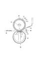
すなわち、本発明は、図1(a)(b)に示すように、記録材4上の未定着像を加熱・加圧定着する定着装置において、加熱源2にて表面が加熱される回転可能な加熱定着部材1と、この加熱定着部材1に接触配置されて記録材4を挟持搬送する定着ベルト3と、定着ベルト3の背面側に配設され且つ加熱定着部材1に対して定着ベルト3を所定の定着ニップ域nにて押し付ける加圧パッド5とを備え、加圧パッド5が、定着ニップ域n内の上流側領域に配置される弾性変形可能な定着パッド6と、定着ニップ域n内の下流側領域に配置され且つ定着パッド6部位よりも高い定着ニップ圧にて押圧可能な剥離パッド7とを有し、剥離パッド7には、定着ベルト3に接触配置され且つ定着ニップ圧では変形不能な剛性体7aとこの剛性体7aを弾性支持する弾性体7bとを具備させ、記録材4が剥離パッド7部位を通過する際に剥離パッド7による記録材4の長手方向両端定着ニップ圧と中央定着ニップ圧との差を記録材4の両端部カールが予め決められた許容量以下に抑制可能な範囲に収めるように、弾性体7bの厚さLbを剛性体7aのそれよりも厚く調整したことを特徴とするものである。
尚、図1(a)は本発明を説明するための模式図、同図(b)は(a)中のB部拡大図であり、本発明は図1(a)(b)に示す態様に限定されるものでないことは勿論である。
The present inventors have examined the cause of uneven wear of the recording material curl and the fixing nip area peripheral member, and by devising the configuration of the peeling pad, a configuration that keeps the fixing property and the peeling property to the recording material favorable. The inventors have found a mechanism in which pressure concentration does not occur in the fixing nip region corresponding to the peeling pad, and have come up with the present invention.
That is, according to the present invention, as shown in FIGS. 1A and 1B, in a fixing device that heats and presses and fixes an unfixed image on a recording material 4, the surface is heated by a
1A is a schematic diagram for explaining the present invention, FIG. 1B is an enlarged view of a portion B in FIG. 1A, and the present invention is an embodiment shown in FIGS. 1A and 1B. Of course, it is not limited to.
このような技術的手段において、本発明は加圧パッド5が定着ニップ圧が低い定着パッド6と定着ニップ圧が高い剥離パッド7とを備えた態様を前提とする。
定着パッド6は剥離パッド7より低い定着ニップ圧を有するものであるため、通常剥離パッド7の弾性体7bより低硬度の弾性体が用いられる。
また、定着パッド6と剥離パッド7の弾性体7bとは通常別体で構成されるが、予め分離される態様に限られず、両者を一体的に接合したものであってもよい。
更に、剥離パッド7の剛性体7aは定着ニップ圧では変形不能な程度の剛性を備えていればよく、金属、合成樹脂、セラミックスなど適宜選定可能である。
一方、剥離パッド7の弾性体7bとしてはフッ素ゴムを始め適宜選定可能である。
In such technical means, the present invention assumes that the pressure pad 5 includes a
Since the
In addition, the
Furthermore, the
On the other hand, the
更にまた、剥離パッド7の弾性体7bの厚さが薄すぎると、記録材4の両端部カールが抑制不能になるため、弾性体7bの厚さを記録材4の両端部カールが抑制可能な範囲に調整することが必要である。
つまり、図2(a)(b)に示すように、記録材4が剥離パッド7部位を通過する際の剥離パッド7に対応した定着ニップ域での圧力分布は、剥離パッド7による記録材4の長手方向両端定着ニップ圧を最大圧力Pmaxとし、その中央定着ニップ圧を最小圧力Pminとするものである。このような状態において、最大圧力Pmaxと最小圧力Pminとの差ΔPが大きいと、記録材4の両端部カールが発生してしまうことから、この圧力差ΔPを記録材4の両端部カールが抑制可能な範囲に収めるようにすることが必要である。
Furthermore, if the thickness of the
That is, as shown in FIGS. 2A and 2B, the pressure distribution in the fixing nip region corresponding to the
また、本発明において、剥離パッド7の弾性体7bの厚さ関係としては、弾性体7bの厚さが剛性体7aのそれよりも厚いものが挙げられる。本態様によれば、弾性体7bの弾性変形により記録材4の両端部カールを確実に抑制することができる点で好ましい。
ここで、剛性体7aの厚さLaが弾性体7bの厚さLb以上である態様にあっても、弾性体7bの厚さが剛性体7aのそれに近いものであれば記録材4のカール抑制は可能であり、一方、弾性体7bの厚さが厚すぎると、記録材4に対する定着性や剥離性が損なわれてしまうため、これらの基本性能を維持する範囲で選定することが必要である。
剛性体7aと弾性体7bとの厚さ比の代表的態様としては、弾性体7bの厚さLb:剛性体7aの厚さLa=6:7〜4:9の範囲内が挙げられる。これは、弾性体7bの硬度を変化させた各実施例にてカール抑制評価を行ったところ、この厚さ比について良好な結果が得られた。
In the present invention, the thickness relationship of the
Here, even if the thickness La of the
A typical aspect of the thickness ratio between the
更に、剥離パッド7の弾性体7bの好ましい態様としては、加熱定着部材1と定着ベルト3との間の定着ニップ域nにて記録材4がニップ搬送されると共に定着ニップ域nの記録材搬送方向に直交する方向で記録材4がニップ搬送されていない部分を有する条件下で、記録材4がニップされていない定着ニップ域nでは加熱定着部材1と定着ベルト3とが接触可能になるように弾性体7bを弾性変形させるものが挙げられる。本態様によれば、図2(b)に示すように、弾性体7bのδだけの弾性変形により剥離パッド7が記録材4の挟み込みに追従して形状が倣うことから、部分的な圧力集中が発生し難くなり、その分、剥離パッド7や加熱定着部材1の偏摩耗を有効に防止することが可能である。
Further, as a preferable aspect of the
更にまた、剥離パッド7の好ましい態様としては、アスカC硬度が30度〜70度の弾性体7bを備えているものが挙げられる。
ここで、30度未満であると、剥離パッド7の剛性が損なわれ、剥離に必要な定着ニップ圧が得難い。一方、70度を超えると、剥離パッド7の弾性作用が損なわれ、定着ニップ圧差を小さく抑え難い。
また、本発明では、加熱定着部材1はロール状、ベルト状適宜選定して差し支えないが、定着ニップ域nをより確実に確保するという観点からすれば、加熱定着部材1としては弾性層1aを具備し、加熱定着部材1と加圧パッド5にて押し付けられる定着ベルト3との間に所望の定着ニップ域nを確保することが好ましい。
Furthermore, as a preferable aspect of the
Here, if it is less than 30 degrees, the rigidity of the
In the present invention, the
また、本発明は、記録材4上に未定着像を形成する作像エンジン(図示せず)と、記録材上の未定着像を加熱・加圧定着する定着装置とを備えた画像形成装置をも対象とし、この場合、定着装置として上述した態様の定着装置を用いるようにすればよい。
更にまた、本発明は、図1(a)(b)に示すように、加熱源2にて表面が加熱される回転可能な加熱定着部材1と、この加熱定着部材1に接触配置されて記録材4を挟持搬送する定着ベルト3とを備え、記録材4上の未定着像を加熱・加圧定着する定着装置に用いられると共に、定着ベルト3の背面側に配設され且つ加熱定着部材1に対して定着ベルト3を所定の定着ニップ域nにて押し付ける加圧パッド5をも対象とする。
つまり、本発明に係る加圧パッド5は、図1に示すように、定着ニップ域n内の上流側領域に配置される弾性変位可能な定着パッド6と、定着ニップ域n内の下流側領域に配置され且つ定着パッド6部位よりも高い定着ニップ圧にて押圧可能な剥離パッド7とを有し、剥離パッド7には、定着ベルト3に接触配置され且つ定着ニップ圧では変形不能な剛性体7aとこの剛性体7aを弾性支持する弾性体7bとを具備させ、記録材4が剥離パッド7部位を通過する際に剥離パッド7による記録材4の長手方向両端定着ニップ圧と中央定着ニップ圧との差を記録材4の両端部カールが予め決められた許容量以下に抑制可能な範囲に収めるように、弾性体7bの厚さを剛性体7aのそれよりも厚く調整したことを特徴とするものである。
The present invention also includes an image forming engine (not shown) for forming an unfixed image on the recording material 4 and a fixing device for heating and pressure-fixing the unfixed image on the recording material. In this case, the fixing device of the above-described embodiment may be used as the fixing device.
Furthermore, in the present invention, as shown in FIGS. 1 (a) and 1 (b), a rotatable
That is, the pressure pad 5 according to the present invention includes an elastically
本発明に係る定着装置によれば、定着ベルト方式における加圧パッドとして、定着ニップ圧が低い定着パッドとその下流側に定着ニップ圧が高い剥離パッドとを配設し、更に、剥離パッドに剛性機能と弾性機能とを共存させるようにしたので、広い定着ニップ域及び記録材の剥離に必要な定着ニップ圧分布を容易に得ることができ、しかも、剥離パッドに対応した定着ニップ域に小サイズの記録材が通過したとしても、当該定着ニップ域での定着ニップ圧分布につき圧力集中を有効に防止することができる。
このため、以下のような基本的効果を奏することができる。
(1)定着装置の基本的性能である記録材に対する定着性及び剥離性を良好に保つことができる。
(2)記録材に対して定着に必要な圧力以上の外力が作用しないため、記録材の両端部カールなどの記録材品質問題を有効に防止することができる。
(3)定着ニップ域の剥離パッドに対応した部位にて部分的な圧力集中が生じないので、定着ニップ域の周辺部材(定着ベルトや加熱定着部材)が偏摩耗する虞れはなくなり、その分、定着ニップ域の周辺部材の寿命を延ばすことができる。
(4)従来の定着装置によれば、定着ニップ域の剥離パッドに対応した部位にて部分的な圧力集中が生ずる場合には、加熱定着部材の支持構造について圧力集中荷重に耐える構成にしなくてはならず、結果として重量・大きさに制約が生じ、また、加工精度と強度とを両立しなくてはならないという不具合が生ずる。ところが、本発明に係る定着装置にあっては、定着ニップ域の剥離パッドに対応した部位にて部分的な圧力集中が生じないので、圧力集中が生ずる場合に比べて加熱定着部材の支持構造を簡素化、軽量化することができる。
According to the fixing device of the present invention, as a pressure pad in the fixing belt system, a fixing pad having a low fixing nip pressure and a peeling pad having a high fixing nip pressure are disposed on the downstream side thereof. Since the function and the elastic function coexist, a wide fixing nip area and fixing nip pressure distribution necessary for peeling of the recording material can be easily obtained, and the fixing nip area corresponding to the peeling pad has a small size. Even when the recording material passes, pressure concentration can be effectively prevented with respect to the fixing nip pressure distribution in the fixing nip region.
For this reason, the following basic effects can be produced.
(1) It is possible to maintain good fixability and releasability with respect to a recording material, which is the basic performance of the fixing device.
(2) Since an external force exceeding the pressure necessary for fixing does not act on the recording material, it is possible to effectively prevent recording material quality problems such as curling at both ends of the recording material.
(3) Since partial pressure concentration does not occur at the part corresponding to the peeling pad in the fixing nip region, there is no possibility that the peripheral members (fixing belt and heat fixing member) in the fixing nip region will be unevenly worn. The life of peripheral members in the fixing nip region can be extended.
(4) According to the conventional fixing device, when a partial pressure concentration occurs at a portion corresponding to the peeling pad in the fixing nip region, the supporting structure of the heat fixing member must be configured to withstand the pressure concentration load. As a result, the weight and size are restricted, and there is a problem that both processing accuracy and strength must be compatible. However, in the fixing device according to the present invention, since the partial pressure concentration does not occur at the portion corresponding to the peeling pad in the fixing nip region, the support structure for the heat fixing member is provided as compared with the case where the pressure concentration occurs. Simplification and weight reduction can be achieved.
また、上述した定着装置を用いた画像形成装置にあっては、記録材に対する定着性及び剥離性を良好に保ちながら、記録材の両端部カール及び定着ニップ域の周辺部材の偏摩耗を有効に防止する定着装置を用いたので、定着性能の良好な画像形成装置を簡単に構築することができる。
更に、上述した定着装置で用いられる加圧パッドにあっては、定着性能の良好な定着ベルト方式の定着装置を簡単に構築することができる。
Further, in the image forming apparatus using the above-described fixing device, it is possible to effectively prevent uneven wear of the peripheral members in the both ends curl of the recording material and the fixing nip region while maintaining good fixing property and peelability to the recording material. Since the fixing device for preventing the above is used, it is possible to easily construct an image forming apparatus having good fixing performance.
Further, with the pressure pad used in the above-described fixing device, a fixing belt type fixing device with good fixing performance can be easily constructed.
以下、添付図面に示す実施の形態に基づいてこの発明を詳細に説明する。
◎実施の形態1
−画像形成装置の全体構成−
図3は本発明が適用された画像形成装置の実施の形態1を示す。
同図において、本実施の形態の画像形成装置は、装置筐体10内にカラー画像が形成可能な作像エンジン20を有し、装置筐体10の上部に原稿が読取り可能な画像読取ユニット11を配設すると共に、その上方に画像読取ユニット11に原稿が送出される原稿送り装置12を配設する一方、装置筐体10の作像エンジン20の下方には、記録材としての用紙が供給可能な多段の給紙トレイ51〜53を配設したものである。尚、符号57は装置筐体10の側方に設けられ且つ作像エンジン20にて作像された用紙が収容排出される排出トレイである。
Hereinafter, the present invention will be described in detail based on embodiments shown in the accompanying drawings.
-Overall configuration of image forming apparatus-
FIG. 3 shows
In the figure, the image forming apparatus of the present embodiment has an
本実施の形態で用いられる作像エンジン20は、イエロ(Y色)、マゼンタ(M色)、シアン(C色)及びブラック(K色)の4色の作像ユニット21(21a〜21d)を並列配置した所謂タンデム型であって、各作像ユニット21にて形成した各色成分トナー像を中間転写ベルト30に一次転写させ、二次転写装置35にて給紙トレイ51〜53から供給される用紙に中間転写ベルト30上の各色成分トナー像を二次転写させ、定着装置40に導くようにしたものである。尚、4色の作像ユニット21の配色はこの順番に限らず、他の順番であっても差し支えない。
The
本実施の形態における作像ユニット21(21a〜21d)は、例えば電子写真方式を採用したものであって、各色成分トナー像を形成担持する感光体ドラム22と、この感光体ドラム22を帯電する帯電ロール等の帯電装置23、帯電された感光体ドラム22に潜像を形成するレーザ露光装置24、感光体ドラム22上の静電潜像を顕像化する現像装置25、感光体ドラム22上のトナー像を中間転写ベルト30上に一次転写する例えば一次転写ロールからなる一次転写装置26、感光体ドラム22上に残留した残留トナーを清掃するクリーニング装置27にて構成されている。尚、本実施の形態では、レーザ露光装置24は、4色の作像ユニット21全体を一つのレーザ露光装置24にて露光するようになっている。
また、中間転写ベルト30は、複数の張架ロール31〜33に張架され、例えば張架ロール31を駆動ロールとして循環搬送されるものであり、例えば二次転写ロールからなる二次転写装置35が張架ロール33をバックアップロールとして対向配置されている。更に、この中間転写ベルト30の張架ロール32と対向する位置には、中間転写ベルト30上の残留トナーを除去するベルトクリーニング装置36が配設されている。
The image forming unit 21 (21a to 21d) in the present embodiment adopts, for example, an electrophotographic system, and charges the
Further, the intermediate transfer belt 30 is stretched around a plurality of stretching
更に、本実施の形態における用紙搬送系は、夫々の給紙カセット51〜53から略垂直上方に延びる垂直搬送路61と、この垂直搬送路61の下流側にて略水平に延び且つ作像エンジン20の二次転写部位、定着装置40を経て排出トレイ57側へ向かう主搬送路62と、主搬送路62の最下流近傍に略Y字状に下方に延び且つ用紙の表裏を反転させて搬送する反転搬送路63と、この反転搬送路63の一部に連通接続され、表裏を反転したシートを再び作像エンジン20前の垂直搬送路61まで戻す戻し搬送路64とを備えている。
そして、主搬送路62の二次転写部位の上流側には用紙を位置決めした後に搬送するレジストロール54が、二次転写部位の下流側には定着装置40へ搬送する搬送ベルト55が、更に、主搬送路62の出口には排出トレイ57へ用紙を排出する排出ロール56が設けられている。更にまた、反転搬送路63にはシートの表裏を反転して搬送する反転機構65が配設されている。尚、これらの搬送路61〜64には用紙の搬送を確実にする搬送ロール66や搬送ガイド(図示せず)等の搬送部材が適宜配設されている。
Further, the sheet conveyance system in the present embodiment includes a
A
−定着装置−
本実施の形態において、定着装置40は、図4に示すように、ハロゲンランプ等の加熱源42を内部に備える加熱定着ロール41と、加熱定着ロール41と転動して用紙を挟持搬送する定着ベルト43と、定着ベルト43の背面側に接触配置されて加熱定着ロール41と定着ベルト43との間に定着ニップ域nを形成する加圧パッド46とを備えている。
そして、定着ベルト43内では凹部44a(図5参照)を有する支持台44が設けられており、この支持台44の凹部44aに前記加圧パッド46が嵌合保持され、定着ベルト43を介して加熱定着ロール41を定着ニップ域nにて押圧するようになっている。
更に、支持台44の下部には、定着ベルト43をスムーズに回転させるために例えば剛性且つ低熱伝導性の樹脂からなるベルト走行ガイド45が設けられている。
更にまた、加熱定着ロール41の周囲には、加熱定着ロール41の表面温度を計測する温度センサ49が配設され、この温度センサ49によって加熱定着ロール41の表面温度が所定の温度になるように加熱源42の温度制御が行われるようになっている。尚、温度センサ49としては加熱定着ロール41の表面温度を計測できるものであれば特に制限されず、例えばサーミスタやポジスタ等の感温素子も使用できる。
また、定着ニップ域nより下流側で加熱定着ロール41に対向する位置には、定着ニップ域nより排出された用紙の加熱定着ロール41への付着を防ぐ剥離補助板48が近接若しくは接触して設けられている。
-Fixing device-
In the present embodiment, as shown in FIG. 4, the fixing
A
Further, a
Further, a
Further, at a position facing the
本実施の形態で用いられる加熱定着ロール41は、機械的強度に優れ且つ熱伝導性が良好なアルミニウム等の金属製の円筒状のコア41aと、このコア41aの表面に形成されたシリコーンゴム等の弾性層41bと、この弾性層41bの表面に被覆され、用紙上の未定着トナー像のオフセットを防止するために設けられた離型層41cとで構成されている。
ここで、コア41aとしては、機械的強度と良好な熱伝導性を備えていれば特に材質は制限されず、例えばステンレス、鋼、黄銅等の金属や合金であっても差し支えない。
また、弾性層41bとしては、シリコーンゴムに限らず、耐熱性を備えていれば、例えばフッ素系ゴム等も使用でき、この弾性層41bをコア41aの表面に形成する方法も特に制限されず、注入成形法やコーティング法等が採用できる。
更に、離型層41cは、耐熱性があり、トナーに対する適度な離型性を備えるものであればよく、例えばフッ素系ゴムやフッ素系樹脂等が使用される。
更にまた、加熱定着ロール41内部の加熱源42としては、コア41a内部に収容できる形状、構造のものであれば特に制限されず、目的に応じて適宜選定して差し支えない。また、加熱源42としては、加熱定着ロール41を外部から加熱するものであってもよいし、加熱定着ロール41の内部及び外部の両方から加熱するものであってもよい。
The heat-fixing
Here, the material of the
Further, the
Further, the
Furthermore, the
一方、定着ベルト43は単層構造であってもよいが、本実施の形態では基材表面に離型層を施した積層構造のベルトを使用している。
この定着ベルト43の基材としては、耐熱性を有すれば、例えば熱硬化性ポリイミド、熱可塑性ポリイミド、ポリアミド、ポリアミドイミド等の樹脂基材や、ステンレス、ニッケル、銅合金等の金属基材が用いられる。また、離型層としては、表面に付着するトナーの剥離性が良好なものがよく、その材質としては、例えばPTFE(ポリテトラフルオロエチレン)、PFA(テトラフルオロエチレン−パーフルオロアルコキシエチレン共重合体)、FEP(テトラフルオロエチレン−ヘキサフルオロプロピレン共重合体)等のフッ素系樹脂が用いられる。
On the other hand, the fixing
As the base material of the fixing
更に、本実施の形態における加圧パッド46は、図5(a)(b)に示すように、定着ニップ域n内の上流側領域に配設された弾性変形可能な定着パッド71と、定着ニップ域n内の下流側領域に配設され且つ定着パッド71部位よりも高い定着ニップ圧Ps(定着パッド71部位の定着ニップ圧Pf:Pf<Ps)にて押圧可能な剥離パッド72とに分割されており、両者を隣接配置した状態で前記支持台44の凹部44a内に嵌合配置されている。そして、この加圧パッド46の定着ニップ域nのプロセス方向(用紙搬送方向に相当)の幅寸法は加圧パッド46の長手方向中央部から両端部に亘って略同様になるようになっている。
ここで、定着パッド71は、シリコーンゴム等の弾性材料によって形成され、加熱定着ロール41と定着ベルト43との定着ニップ域nのうちプレニップ域を形成し、用紙上の未定着トナー像を安定して定着するようになっている。尚、この定着パッド71の表面に、定着ベルト43との摩擦抵抗を小さく維持し、定着ベルト43の回転を一層スムーズにするため、例えばフッ素系樹脂シートからなる低摩擦シートを接着等によって設けるようにしても差し支えない。この低摩擦シートとしては、加工性、低摩擦性の観点からPTFE、PFA等のフッ素系樹脂シートが挙げられる。また、ガラス繊維を基体として、それにフッ素系樹脂を含浸もしくはフッ素系樹脂シートを接着したもの等であっても差し支えない。
Further, as shown in FIGS. 5A and 5B, the
Here, the fixing
また、剥離パッド72は、定着ニップ域n内のポストニップ域(剥離ニップ域)を形成するもので、プレニップ域より高い圧力分布がもたらされるようになっている。
特に、本実施の形態では、剥離パッド72は、定着ベルト43の背面に接触配置され且つ定着ニップ圧では変形不能な剛性の高いパッド剛性体72aと、このパッド剛性体72aを弾性支持するパッド弾性体72bとを一体的に接合したものである。
ここで、パッド剛性体72aとしては、例えばアルミニウム、ステンレス、鋼、銅、黄銅等の金属や合金並びに樹脂材料からなる剛性の高い材料が主として使用される。好ましい代表的な素材としては、液晶ポリマーにガラス繊維を添加した複合材料(例えばデュポン社製ゼナイト3226L:商品名)や耐熱性のポリエーテルサルフォン(PES)などの強化素材(例えばNTN社製ベアリーES:商品名)が挙げられ、例えば射出成形にて形成される。
Further, the
In particular, in the present embodiment, the
Here, as the pad
そして、このパッド剛性体72aの形状については、本実施の形態にあっては略直方体形状であるが、これに限られるものではなく、例えば用紙の搬送姿勢を良好に保つという観点から、パッド剛性体72aの頂部面にプロセス方向に向かう所定の傾斜面や曲率面を設けたり、例えば用紙の剥離性能を確保するという観点から、パッド剛性体72aの頂部面の一部を加熱定着ロール41側に膨出させるようにする等適宜設計変更して差し支えない。
従って、定着ニップ域nの剥離パッド72に対応したニップ域の形状は通常は面接触であるが、パッド剛性体72aの形状(例えば、剥離パッド72の加熱定着ロール41側の面に大きな傾斜を与えた形状など)によっては線接触になる態様もある。
そしてまた、パッド剛性体72aは長手方向に一体的に延びる長尺物で差し支えないが、長手方向に沿って複数の分割体として構成し、複数の分割体を柔軟性を持つゴムや紐などの素材を用いて連続体とするようにしてもよい。
The shape of the pad
Accordingly, the shape of the nip area corresponding to the
In addition, the pad
また、パッド弾性体72bとしては、フッ素ゴムなどの弾性素材が用いられる。そして、このパッド弾性体72bの好ましい硬度としては、アスカC硬度で30度〜70度のものが使用される。更に、パッド弾性体72bの形状としては通常略直方体状のものが用いられるが、これに限られるものではなく、パッド剛性体72aとの接合面に合わせて接合面形状を例えばプロセス方向に傾斜させることは適宜選定して差し支えない。
また、パッド剛性体72aとパッド弾性体72bとの厚さ比については、図5(a)に示すように、パッド剛性体72aの厚さをLa、パッド弾性体72bの厚さをLbとすれば、パッド厚さ比=La:Lb=6:7〜4:9の範囲で選定されることが好ましい。
このとき、パッド厚さ比(La:Lb)が6:7の比率よりパッド剛性体72aが厚いと、パッド弾性体72bによる弾性作用が弱すぎ、剥離パッド72に対応した定着ニップ域nでの圧力集中が十分には抑制されない。一方、パッド厚さ比が4:9の比率よりパッド弾性体72bが厚すぎると、パッド剛性体72aによる剛性作用が弱すぎ、剥離パッド72による用紙の剥離作用を損なうという虞れがある。
The pad
As for the thickness ratio between the pad
At this time, if the pad
ここでいうLa、Lbはパッド剛性体72a、パッド弾性体72bが一定の厚さであればその厚さを意味するものであるが、厚さが一定でない形状である場合には、剥離パッド72に対応した定着ニップ域nのうちプロセス方向における定着ニップ圧が最も高い部位が含まれる部分の厚さを代表厚さとするようにすればよい。
Here, La and Lb mean the thickness if the pad
次に、本実施の形態に係る画像形成装置の作動を定着装置を中心に説明する。
今、図3に示す作像エンジン20は、各作像ユニット21にて各色成分トナー像を作成し、中間転写ベルト30に順次一次転写した後、中間転写ベルト30上に多重転写されたトナー像を二次転写装置35にて用紙に一括転写する。
この後、一括転写された用紙上の未定着像は定着装置40の定着ニップ域nにて加熱・加圧定着された後、定着装置40から定着済みの用紙が剥離されて排出される。
今、図5(a)及び図6(a)に示すように、未定着トナー像が保持された大サイズ(S1)の用紙(例えば厚紙)80が定着装置40の定着ニップ域nに進入したと仮定すると、用紙80上の未定着トナー像には加圧パッド46の定着パッド71にて十分な加熱・加圧が施された後、用紙80は剥離パッド72を通過して剥離される。
このとき、剥離パッド72に対応した定着ニップ域nのプロセス方向における定着ニップ圧Psは定着パッド71に対応した部分の定着ニップ圧Pfよりも大きいため、用紙80の先端部分が定着ニップ域nの出口から剥離する方向に向かう。
特に、本実施の形態では、剥離パッド72は、パッド剛性体72aとパッド弾性体72bとの組合せ構成であるため、定着ニップ圧Psを剥離動作に必要な圧力に保ちながら、パッド弾性体72bの弾性作用により剥離パッド72に対応した定着ニップ域の長手方向における定着ニップ圧分布の上昇を抑制する。
このため、大サイズの用紙の長手方向両端部の定着ニップ圧と中央部の定着ニップ圧との差分はあまり大きくなく、パッド弾性体72bの厚さLbを適宜調整してあるため、定着ニップ圧の差分が用紙80の両端部カールが発生しない程度に抑えられ、これにより、用紙80の両端部カールは有効に抑えられる。
Next, the operation of the image forming apparatus according to the present embodiment will be described focusing on the fixing device.
Now, the
Thereafter, the unfixed image on the batch-transferred paper is fixed by heating and pressure in the fixing nip area n of the fixing
Now, as shown in FIGS. 5A and 6A, a large-size (S1) sheet (for example, a thick sheet) 80 holding an unfixed toner image has entered the fixing nip region n of the fixing
At this time, since the fixing nip pressure Ps in the process direction of the fixing nip area n corresponding to the
In particular, in the present embodiment, the
For this reason, the difference between the fixing nip pressure at both ends in the longitudinal direction and the fixing nip pressure at the center of a large size sheet is not so large, and the thickness Lb of the pad
また、図5(a)及び図6(b)に示すように、未定着トナー像が保持された小サイズ(S2)の用紙(例えば厚紙)80が定着装置40の定着ニップ域nに進入したと仮定すると、用紙80上の未定着トナー像には加圧パッド46の定着パッド71にて十分な加熱・加圧が施された後、用紙80は剥離パッド72を通過して剥離される。
このとき、定着パッド71、剥離パッド72に対応した定着ニップ域nのプロセス方向における定着ニップ圧分布により、用紙80の先端部分が定着ニップ域nの出口から剥離する方向に向かう。
そして、本実施の形態では、剥離パッド72(パッド剛性体72a+パッド弾性体72b)は、定着ニップ圧Psを剥離動作に必要な圧力に保ちながら、パッド弾性体72bの弾性作用により剥離パッド72に対応した定着ニップ域の長手方向における定着ニップ圧分布の上昇を抑制することに加えて、剥離パッド72に対応した定着ニップ域nのうち、用紙80が介在しない領域では、剥離パッド72のパッド弾性体72bがパッド剛性体72aを定着ベルト40側δだけに押し付けるため、定着ベルト43と加熱定着ロール41とが接触配置される。つまり、本実施の形態にあっては、パッド剛性体72aの存在により加熱定着ロール41に対向する方向についての剛性は維持しつつ、パッド弾性体72bの存在により、剥離パッド72の長手方向の曲げ剛性を低減させることが可能になるのである。
このため、小サイズの用紙の長手方向両端部の定着ニップ圧と中央部の定着ニップ圧との差分はあまり大きくなく、パッド弾性体72bの厚さLbを適宜調整してあるため、定着ニップ圧の差分が用紙80の両端部カールが発生しない程度に抑えられ、これにより、用紙80の両端部カールは有効に抑えられる。また、パッド弾性体72bの弾性変形により剥離パッド72の形状が用紙80の挟み込みに追従して倣うことから、定着ニップ域nにおける部分的な圧力集中が発生し難くなり、その分、剥離パッド72や加熱定着ロール41の偏摩耗は有効に防止される。
Further, as shown in FIGS. 5A and 6B, a small size (S2) paper (for example, thick paper) 80 on which an unfixed toner image is held enters the fixing nip area n of the fixing
At this time, due to the fixing nip pressure distribution in the process direction of the fixing nip area n corresponding to the
In this embodiment, the peeling pad 72 (pad
For this reason, the difference between the fixing nip pressure at both ends in the longitudinal direction and the fixing nip pressure at the center of a small size sheet is not so large, and the thickness Lb of the pad
尚、本実施の形態では、定着パッド71と剥離パッド72とを一つの支持台44にて支持する方式を示したが、例えば図7(a)に示すように、支持台44では剥離パッド72のみを支持し、定着パッド71は支持台44との間に付勢スプリング47aを備えた弾性支持台47にて支持させるようにしてもよい。本態様では、定着パッド71自体は弾性素材を用いなくとも、弾性変位可能に支持されるので差し支えない。
ここで、例えば図7(b)に示すように、剥離パッド72のパッド剛性体72a、パッド弾性体72bの厚さが不均一である場合には、定着ニップ域での定着ニップ圧が高くなる部分での厚さLa、Lbを選定するようにすればよい。
In the present embodiment, the fixing
Here, for example, as shown in FIG. 7B, when the thicknesses of the pad
今、実施の形態に係る定着装置(図4)につき、加圧パッド46の剥離パッド72構成を適宜変更し、図8(a)〜(d)に示すように、比較例1,2及び実施例1,2を作成した。
同図において、比較例1は支持台44上にパッド剛性体72a’(例えば液晶ポリマー樹脂デュポン社製ゼナイト)のみからなる剥離パッド72’(全体の厚さ:6.5mm)を使用した態様、比較例2は支持台44上に薄いパッド弾性体72b’(厚さt1=1.5mmのフッ素ゴム(又はシリコーンゴム),アスカC硬度30度)を介してパッド剛性体72a’(厚さ5.0mmの例えば液晶ポリマー樹脂デュポン社製ゼナイト)を組み合わせた態様、実施例1は支持台44上に厚いパッド弾性体72b(厚さt2=3.0mmのフッ素ゴム(又はシリコーンゴム),アスカC硬度70度)を介してパッド剛性体72a(厚さ3.5mmの例えば液晶ポリマー樹脂デュポン社製ゼナイト)を組み合わせた態様、実施例2は支持台44上により厚いパッド弾性体72b(厚さt3=4.5mmのフッ素ゴム(又はシリコーンゴム),アスカC硬度70度)を介してパッド剛性体72a(厚さ2.0mmの例えば液晶ポリマー樹脂デュポン社製ゼナイト)を組み合わせた態様である。
Now, with respect to the fixing device (FIG. 4) according to the embodiment, the configuration of the
In the same figure, the comparative example 1 is the aspect which used peeling pad 72 '(total thickness: 6.5 mm) which consists only of pad
今、実施例1,2及び比較例2について、図4に示した実施の形態に係る定着装置の試験機を用いて、以下の条件で平均カール量(カール量ave.)を測定したところ、図9に示すように、比較例2に比べて、実施例1,2はカール量が少ないことが判明した。
・環境:22℃、55%RH
・定着パッドに対応した定着ニップ幅:4.8mmになるように設定
・定着パッドに対応した定着ニップ圧:面圧2.1kg/cm2になるように設定
・剥離パッドに対応した定着ニップ幅:2.1mmになるように設定
・剥離パッドに対応した定着ニップ圧:面圧4.2kg/cm2になるように設定
・定着速度:280mm/sec
・A4サイズP紙(富士ゼロックスオフィスサプライ社製)の白紙を短手方向を先頭にして走行させて、定着後、平らな面に静置し、4隅のカールの高さを測定し、平均化した。
特に、実施例1,2のうち、パッド弾性体72bの厚さが厚い態様の実施例2の方が実施例1に比べてカール抑制に効果があることが把握される。
For Examples 1 and 2 and Comparative Example 2, the average curl amount (curl amount ave.) Was measured under the following conditions using the fixing device testing machine according to the embodiment shown in FIG. As shown in FIG. 9, it was found that Examples 1 and 2 had a lower curl amount than Comparative Example 2.
・ Environment: 22 ℃, 55% RH
・ Fixing nip width corresponding to the fixing pad: set to be 4.8 mm ・ Fixing nip pressure corresponding to the fixing pad: set to be a surface pressure of 2.1 kg / cm 2・ Fixing nip width corresponding to the peeling pad : Set to 2.1 mm ・ Fixing nip pressure corresponding to peeling pad: Set to surface pressure 4.2 kg / cm 2・ Fixing speed: 280 mm / sec
・ A4 size P paper (manufactured by Fuji Xerox Office Supply Co., Ltd.) was run with the short side first, and after fixing, it was placed on a flat surface, and the curl heights at the four corners were measured. Turned into.
In particular, among Examples 1 and 2, it is understood that Example 2 in which the pad
また、比較例2において、剥離パッド72’のパッド弾性体72b’の硬度を30度、40度、56度、70度と変化させたところ、図10に示すように、パッド弾性体72b’の硬度が低い程、長手方向における品質工学手法を用いた望目SN比は高くなる。ここでいう望目SN比は、値が高いほどばらつきが少なく、定着ニップ圧が所望の値で安定していることを示すものである。
この傾向は実施例1,2においても同様である。
一般に、支持台44のフレームには除去不可能な微小凹凸や20〜30mm周期のうねりが存在するため、例えば図8(a)に示す比較例1にあっては、上述した望目SN比は非常に小さくなってしまい、定着ニップ形成面に微小凹凸などの影響が現れてしまう。これに対し、比較例2及び実施例1,2に示すように、剥離パッド72’,72にパッド弾性体72b’,72bを用いると、定着ニップ形成面に対する微小凹凸などの影響を吸収可能であることが理解される。
In Comparative Example 2, when the hardness of the pad
This tendency is the same in the first and second embodiments.
In general, since there are minute irregularities and undulations with a period of 20 to 30 mm that cannot be removed in the frame of the
また、実施例2及び比較例2について、A4SEF(A4サイズ用紙Short Edge Feed)、A4LEF(A4サイズ用紙Long Edge Feed)を行った際の剥離パッドに対応する定着ニップ域長手方向(軸方向)での定着ニップ圧分布を調べたところ、図11、図12に示す結果が得られた。
図11、図12において、M濃度とは感圧紙反射濃度を示し、色が濃いほど面圧が高いことを意味する。
図11及び図12によれば、実施例2は、比較例2に比べて、用紙の定着ニップ域にて用紙の両端部の定着ニップ圧と用紙の中央部の定着ニップ圧との差圧が低減していることが理解される。
この結果を図13に示す。
つまり、実施例2は定着ニップ圧差が十分に小さいため、その分、用紙の両端部のカールを有効に抑制することができる。
尚、実施例2及び比較例2において、パッド弾性体の硬度を変更したところ、アスカC硬度が30度〜70度の範囲で図11、図12と同様な傾向が確認された。
更に、比較例2及び実施例1,2について、非通紙状態の圧力分布、定着温度ラチチュード及び用紙の両端部カール量について評価したところ、図13に示すような結果が得られた。これによれば、本実施例1,2は比較例2の定着性能に加えて、カール抑制機能を十分に発揮できることが確認された。
Further, in Example 2 and Comparative Example 2, in the fixing nip region longitudinal direction (axial direction) corresponding to the peeling pad when A4SEF (A4 size paper Short Edge Feed) and A4LEF (A4 size paper Long Edge Feed) are performed. When the fixing nip pressure distribution was examined, the results shown in FIGS. 11 and 12 were obtained.
11 and 12, the M density indicates the pressure sensitive paper reflection density, and the darker the color, the higher the surface pressure.
According to FIGS. 11 and 12, in Example 2, the differential pressure between the fixing nip pressure at both ends of the sheet and the fixing nip pressure at the center of the sheet is larger in the fixing nip region of the sheet than in Comparative Example 2. It is understood that there is a reduction.
The result is shown in FIG.
That is, in Example 2, the fixing nip pressure difference is sufficiently small, and accordingly, curling at both ends of the sheet can be effectively suppressed.
In Example 2 and Comparative Example 2, when the hardness of the pad elastic body was changed, the same tendency as in FIGS. 11 and 12 was confirmed when the Asuka C hardness was in the range of 30 to 70 degrees.
Further, Comparative Example 2 and Examples 1 and 2 were evaluated for the non-sheet-passing pressure distribution, the fixing temperature latitude, and the curl amount at both ends of the paper, and the results shown in FIG. 13 were obtained. According to this, it was confirmed that Examples 1 and 2 can sufficiently exhibit the curl suppressing function in addition to the fixing performance of Comparative Example 2.
1…加熱定着部材,1a…弾性層,2…加熱源,3…定着ベルト,4…記録材,5…加圧パッド,6…定着パッド、7…剥離パッド、7a…剛性体、7b…弾性体、La…剛性体の厚さ,Lb…弾性体の厚さ
DESCRIPTION OF
Claims (7)
加熱源にて表面が加熱される回転可能な加熱定着部材と、
この加熱定着部材に接触配置されて記録材を挟持搬送する定着ベルトと、
この定着ベルトの背面側に配設され且つ加熱定着部材に対して定着ベルトを所定の定着ニップ域にて押し付ける加圧パッドとを備え、
前記加圧パッドは、定着ニップ域内の上流側領域に配置される弾性変位可能な定着パッドと、定着ニップ域内の下流側領域に配置され且つ定着パッド部位よりも高い定着ニップ圧にて押圧可能な剥離パッドとを有し、
前記剥離パッドには、定着ベルトに接触配置され且つ定着ニップ圧では変形不能な剛性体とこの剛性体を弾性支持する弾性体とを具備させ、記録材が剥離パッド部位を通過する際に剥離パッドによる記録材の長手方向両端定着ニップ圧と中央定着ニップ圧との差を記録材の両端部カールが予め決められた許容量以下に抑制可能な範囲に収めるように、弾性体の厚さを剛性体のそれよりも厚く調整したことを特徴とする定着装置。 In a fixing device that heats and pressurizes an unfixed image on a recording material,
A rotatable heat fixing member whose surface is heated by a heating source;
A fixing belt disposed in contact with the heat fixing member and sandwiching and conveying the recording material;
A pressure pad disposed on the back side of the fixing belt and pressing the fixing belt against the heat fixing member in a predetermined fixing nip region;
The pressure pad is elastically displaceable fixing pad disposed in the upstream region in the fixing nip region, and is disposed in the downstream region in the fixing nip region and can be pressed at a fixing nip pressure higher than the fixing pad portion. A peeling pad,
The release pad includes a rigid body that is in contact with the fixing belt and cannot be deformed by the fixing nip pressure, and an elastic body that elastically supports the rigid body, and when the recording material passes through the release pad portion, the release pad is provided. The thickness of the elastic body is rigid so that the difference between the fixing nip pressure at both ends in the longitudinal direction of the recording material and the central fixing nip pressure can be kept within a range where the curling at both ends of the recording material can be suppressed to a predetermined allowable amount or less. A fixing device characterized by being adjusted to be thicker than that of the body .
前記剥離パッドは、剛性体の厚さと弾性体の厚さとの比が6:7〜4:9の範囲内であることを特徴とする定着装置。 The fixing device according to claim 1 .
In the fixing device, the ratio of the thickness of the rigid body to the thickness of the elastic body is in the range of 6: 7 to 4: 9.
前記剥離パッドは、加熱定着部材と定着ベルトとの間の定着ニップ域にて記録材がニップ搬送されると共に定着ニップ域の記録材搬送方向に直交する方向で記録材がニップ搬送されていない部分を有する条件下で、記録材がニップされていない定着ニップ域では定着加熱部材と定着ベルトとが接触可能になるように弾性体を弾性変形させるものであることを特徴とする定着装置。 The fixing device according to claim 1.
The peeling pad is a portion where the recording material is nipped and conveyed in the fixing nip area between the heat fixing member and the fixing belt and the recording material is not conveyed in the nip direction in the direction perpendicular to the recording material conveying direction of the fixing nip area. And a fixing device that elastically deforms the elastic body so that the fixing heating member and the fixing belt can come into contact with each other in a fixing nip region where the recording material is not nipped.
前記剥離パッドは、アスカC硬度が30度〜70度の弾性体を備えていることを特徴とする定着装置。 The fixing device according to claim 1.
The fixing device, wherein the peeling pad includes an elastic body having an Asuka C hardness of 30 degrees to 70 degrees.
前記加熱定着部材は弾性層を有することを特徴とする定着装置。 The fixing device according to claim 1.
The fixing device according to claim 1, wherein the heat fixing member has an elastic layer.
記録材上の未定着像を加熱・加圧定着する定着装置とを備え、
前記定着装置は、加熱源にて表面が加熱される回転可能な加熱定着部材と、
この加熱定着部材に接触配置されて記録材を挟持搬送する定着ベルトと、
この定着ベルトの背面側に配設され且つ加熱定着部材に対して定着ベルトを所定の定着ニップ域にて押し付ける加圧パッドとを備え、
前記加圧パッドは、定着ニップ域内の上流側領域に配置される弾性変位可能な定着パッドと、定着ニップ域内の下流側領域に配置され且つ定着パッド部位よりも高い定着ニップ圧にて押圧可能な剥離パッドとを有し、
前記剥離パッドには、定着ベルトに接触配置され且つ定着ニップ圧では変形不能な剛性体とこの剛性体を弾性支持する弾性体とを具備させ、記録材が剥離パッド部位を通過する際に剥離パッドによる記録材の長手方向両端定着ニップ圧と中央定着ニップ圧との差を記録材の両端部カールが予め決められた許容量以下に抑制可能な範囲に収めるように、弾性体の厚さを剛性体のそれよりも厚く調整したことを特徴とする画像形成装置。 An imaging engine that forms an unfixed image on the recording material;
A fixing device that heats and presses and fixes an unfixed image on the recording material,
The fixing device includes a rotatable heat fixing member whose surface is heated by a heating source;
A fixing belt disposed in contact with the heat fixing member and sandwiching and conveying the recording material;
A pressure pad disposed on the back side of the fixing belt and pressing the fixing belt against the heat fixing member in a predetermined fixing nip region;
The pressure pad is elastically displaceable fixing pad disposed in the upstream region in the fixing nip region, and is disposed in the downstream region in the fixing nip region and can be pressed at a fixing nip pressure higher than the fixing pad portion. A peeling pad,
The release pad includes a rigid body that is in contact with the fixing belt and cannot be deformed by the fixing nip pressure, and an elastic body that elastically supports the rigid body, and when the recording material passes through the release pad portion, the release pad is provided. The thickness of the elastic body is rigid so that the difference between the fixing nip pressure at both ends in the longitudinal direction of the recording material and the central fixing nip pressure can be kept within a range where the curling at both ends of the recording material can be suppressed to a predetermined allowable amount or less. An image forming apparatus characterized by being adjusted to be thicker than that of a body .
定着ニップ域内の上流側領域に配置される弾性変位可能な定着パッドと、定着ニップ域内の下流側領域に配置され且つ定着パッド部位よりも高い定着ニップ圧にて押圧可能な剥離パッドとを有し、
前記剥離パッドには、定着ベルトに接触配置され且つ定着ニップ圧では変形不能な剛性体とこの剛性体を弾性支持する弾性体とを具備させ、記録材が剥離パッド部位を通過する際に剥離パッドによる記録材の長手方向両端定着ニップ圧と中央定着ニップ圧との差を記録材の両端部カールが予め決められた許容量以下に抑制可能な範囲に収めるように、弾性体の厚さを剛性体のそれよりも厚く調整したことを特徴とする加圧パッド。 A rotatable heat fixing member whose surface is heated by a heating source, and a fixing belt which is disposed in contact with the heat fixing member and sandwiches and conveys the recording material, and heats and pressurizes an unfixed image on the recording material. A pressure pad that is used in a fixing device for fixing, is disposed on the back side of the fixing belt, and presses the fixing belt against a heat fixing member in a predetermined fixing nip region;
An elastically displaceable fixing pad disposed in an upstream region in the fixing nip region, and a peeling pad disposed in a downstream region in the fixing nip region and capable of being pressed with a fixing nip pressure higher than the fixing pad portion. ,
The release pad includes a rigid body that is in contact with the fixing belt and cannot be deformed by the fixing nip pressure, and an elastic body that elastically supports the rigid body, and when the recording material passes through the release pad portion, the release pad is provided. The thickness of the elastic body is rigid so that the difference between the fixing nip pressure at both ends in the longitudinal direction of the recording material and the central fixing nip pressure can be kept within a range where the curling at both ends of the recording material can be suppressed to a predetermined allowable amount or less. A pressure pad adjusted to be thicker than that of the body .
Priority Applications (1)
| Application Number | Priority Date | Filing Date | Title |
|---|---|---|---|
| JP2006104422A JP4857873B2 (en) | 2006-04-05 | 2006-04-05 | Fixing apparatus, image forming apparatus using the same, and pressure pad |
Applications Claiming Priority (1)
| Application Number | Priority Date | Filing Date | Title |
|---|---|---|---|
| JP2006104422A JP4857873B2 (en) | 2006-04-05 | 2006-04-05 | Fixing apparatus, image forming apparatus using the same, and pressure pad |
Publications (3)
| Publication Number | Publication Date |
|---|---|
| JP2007279314A JP2007279314A (en) | 2007-10-25 |
| JP2007279314A5 JP2007279314A5 (en) | 2009-04-02 |
| JP4857873B2 true JP4857873B2 (en) | 2012-01-18 |
Family
ID=38680840
Family Applications (1)
| Application Number | Title | Priority Date | Filing Date |
|---|---|---|---|
| JP2006104422A Expired - Fee Related JP4857873B2 (en) | 2006-04-05 | 2006-04-05 | Fixing apparatus, image forming apparatus using the same, and pressure pad |
Country Status (1)
| Country | Link |
|---|---|
| JP (1) | JP4857873B2 (en) |
Families Citing this family (2)
| Publication number | Priority date | Publication date | Assignee | Title |
|---|---|---|---|---|
| JP2012137555A (en) * | 2010-12-24 | 2012-07-19 | Fuji Xerox Co Ltd | Fixing device, image forming apparatus |
| JP2015169893A (en) | 2014-03-10 | 2015-09-28 | 株式会社リコー | Fixation device and image forming apparatus including fixation device |
Family Cites Families (5)
| Publication number | Priority date | Publication date | Assignee | Title |
|---|---|---|---|---|
| JP2002148981A (en) * | 2000-11-09 | 2002-05-22 | Fuji Xerox Co Ltd | Fixing device |
| JP2002372887A (en) * | 2001-06-13 | 2002-12-26 | Fuji Xerox Co Ltd | Fixing device |
| JP4178939B2 (en) * | 2002-12-17 | 2008-11-12 | 富士ゼロックス株式会社 | Fixing apparatus and electrophotographic apparatus using the same |
| JP4539252B2 (en) * | 2004-09-15 | 2010-09-08 | 富士ゼロックス株式会社 | Fixing device and image forming apparatus |
| JP3812594B2 (en) * | 2005-12-27 | 2006-08-23 | 富士ゼロックス株式会社 | Image fixing device |
-
2006
- 2006-04-05 JP JP2006104422A patent/JP4857873B2/en not_active Expired - Fee Related
Also Published As
| Publication number | Publication date |
|---|---|
| JP2007279314A (en) | 2007-10-25 |
Similar Documents
| Publication | Publication Date | Title |
|---|---|---|
| US7493074B2 (en) | Fixing device, sheet member, and image forming apparatus | |
| US9164435B2 (en) | Fixing device and image forming apparatus | |
| US7764915B2 (en) | Elastic roll and fixing device | |
| US7177580B2 (en) | Image forming method and apparatus for fixing an image | |
| US20090010686A1 (en) | Fixing device, fixing belt, and image forming apparatus | |
| JP2008225021A (en) | Fixing device and image forming apparatus | |
| JP2004226815A (en) | Heating device and image forming apparatus | |
| JP4595596B2 (en) | Fixing device and image forming apparatus using the same | |
| JP2012042853A (en) | Paper separation device, fixing device, and image forming apparatus | |
| JP6249836B2 (en) | Fixing device | |
| US20090180821A1 (en) | Fixing device and image forming apparatus including the same | |
| JP4857873B2 (en) | Fixing apparatus, image forming apparatus using the same, and pressure pad | |
| JP6171563B2 (en) | Fixing apparatus and image forming apparatus | |
| JP6737129B2 (en) | Fixing device and image forming apparatus | |
| JP2005050693A (en) | Heating device and image forming device | |
| JP5549514B2 (en) | Fixing apparatus and image forming apparatus | |
| JP4770453B2 (en) | Fixing device and image forming apparatus using the same | |
| US8626047B2 (en) | Fixing device for fixing developer to recording material and image forming apparatus equipped with the same | |
| US9128436B2 (en) | Fixing device, and image forming apparatus | |
| JP2007086530A (en) | Fixing device and image forming apparatus | |
| JP7153188B2 (en) | Fixing device and image forming device | |
| US11841658B2 (en) | Fixing apparatus with a detection element disposed in a hole portion of a heater holder member and image forming apparatus | |
| JP7276700B2 (en) | Fixing device and image forming device | |
| JP2007240623A (en) | Image heating device | |
| JP2005266716A (en) | Fixing device and image forming apparatus |
Legal Events
| Date | Code | Title | Description |
|---|---|---|---|
| A521 | Written amendment |
Free format text: JAPANESE INTERMEDIATE CODE: A523 Effective date: 20090216 |
|
| A621 | Written request for application examination |
Free format text: JAPANESE INTERMEDIATE CODE: A621 Effective date: 20090216 |
|
| A977 | Report on retrieval |
Free format text: JAPANESE INTERMEDIATE CODE: A971007 Effective date: 20110707 |
|
| A131 | Notification of reasons for refusal |
Free format text: JAPANESE INTERMEDIATE CODE: A131 Effective date: 20110712 |
|
| A521 | Written amendment |
Free format text: JAPANESE INTERMEDIATE CODE: A523 Effective date: 20110906 |
|
| TRDD | Decision of grant or rejection written | ||
| A01 | Written decision to grant a patent or to grant a registration (utility model) |
Free format text: JAPANESE INTERMEDIATE CODE: A01 Effective date: 20111004 |
|
| A01 | Written decision to grant a patent or to grant a registration (utility model) |
Free format text: JAPANESE INTERMEDIATE CODE: A01 |
|
| A61 | First payment of annual fees (during grant procedure) |
Free format text: JAPANESE INTERMEDIATE CODE: A61 Effective date: 20111017 |
|
| R150 | Certificate of patent or registration of utility model |
Free format text: JAPANESE INTERMEDIATE CODE: R150 |
|
| FPAY | Renewal fee payment (event date is renewal date of database) |
Free format text: PAYMENT UNTIL: 20141111 Year of fee payment: 3 |
|
| LAPS | Cancellation because of no payment of annual fees |