JP4856956B2 - Document reading apparatus and image forming apparatus - Google Patents
Document reading apparatus and image forming apparatus Download PDFInfo
- Publication number
- JP4856956B2 JP4856956B2 JP2006013114A JP2006013114A JP4856956B2 JP 4856956 B2 JP4856956 B2 JP 4856956B2 JP 2006013114 A JP2006013114 A JP 2006013114A JP 2006013114 A JP2006013114 A JP 2006013114A JP 4856956 B2 JP4856956 B2 JP 4856956B2
- Authority
- JP
- Japan
- Prior art keywords
- image forming
- sheet
- sheet material
- forming apparatus
- post
- Prior art date
- Legal status (The legal status is an assumption and is not a legal conclusion. Google has not performed a legal analysis and makes no representation as to the accuracy of the status listed.)
- Expired - Fee Related
Links
Images


Description
この発明は、原稿読取装置および画像形成装置に関し、特に、電動綴じ処理手段である電動ステープル装置を備えた小型の複写機、ファクシミリ装置(FAX)、複合機(MFP)に適用して好適なものである。
BACKGROUND OF THE INVENTION 1. Field of the Invention The present invention relates to a document reading apparatus and an image forming apparatus, and is particularly suitable for being applied to a small-sized copying machine, a facsimile machine (FAX), and a multifunction machine (MFP) equipped with an electric stapling device that is an electric binding processing unit. It is.
画像を形成した後の用紙束をステープル処理する画像形成装置システムは数多く発案されている。例えば特許文献1には、画像形成装置に隣接して設置するようなコンソールタイプ(別体据え置き型)の、複写機に隣接設置されるスタッカに内蔵される電動ステープラが開示されている。 Many image forming apparatus systems for stapling a sheet bundle after forming an image have been proposed. For example, Patent Document 1 discloses an electric stapler built in a stacker of a console type (separately installed type) installed adjacent to an image forming apparatus and adjacent to a copying machine.
この特許文献1に記載の電動ステープラにおいては、ユーザは用紙束をステープルしようとする場合、次の2つの方法が採用されている。 In the electric stapler described in Patent Document 1, the following two methods are employed when a user attempts to staple a sheet bundle.
すなわち、第1の方法は、印刷前にあらかじめホストコンピュータにおいてステープル処理をする指示をして印刷を行う方法である。第2の方法は、コピー終了後、排紙ビンから用紙束を取り出す前にステープルを指示するボタンを押すなどの指示を装置に与えることによって、ステープル処理を行う方法である。 That is, the first method is a method of performing printing by instructing a staple process in the host computer in advance before printing. The second method is a method of performing stapling processing by giving an instruction to the apparatus such as pressing a button for instructing stapling after the copying is finished and before taking out the sheet bundle from the paper discharge bin.
このようなスタッカに設けられる電動ステープラは、複数の排紙ビンの紙に対して処理する。そのため、この電動ステープラは、用紙束からオフセットした位置にパンチ機構が設けられている。そして、このパンチ機構は、ステープル動作時のみ排紙ビンの用紙束まで移動され、ステープル処理後に退避させる必要がある。 The electric stapler provided in such a stacker processes paper on a plurality of paper discharge bins. Therefore, this electric stapler is provided with a punch mechanism at a position offset from the sheet bundle. The punch mechanism is moved to the sheet bundle in the paper discharge bin only during the stapling operation and needs to be retracted after the stapling process.
一方、特許文献2にも電動ステープラが提案されている。特許文献2においては、画像形成装置上方に設置される用紙後処理装置に装着する電動ステープラも提案されている。このような電動ステープラの場合は、複数の用紙束を複数まとめて処理しない代わりに、パンチ機構は常に用紙搬送路内に設置されていることから、画像形成装置の設置面積内に電動ステープラを配置することも可能である。
しかしながら、特許文献1の例では、スタッカに電動ステープラが備えられたものであり、画像形成装置の設置面積以外に追加の設置面積を必要としていた。 However, in the example of Patent Document 1, an electric stapler is provided in the stacker, and an additional installation area is required in addition to the installation area of the image forming apparatus.
また、上述した特許文献2に記載された電動ステープラにおいては、画像形成装置の単体と同等の設置面積で電動ステープラを設置することができる。ところが、この特許文献2に記載された電動ステープラは、搬送路中に設置されるものである。そのため、この電動ステープラにより、排紙後の用紙束を後処理でステープルすることができない。 In the electric stapler described in Patent Document 2 described above, the electric stapler can be installed with an installation area equivalent to that of a single image forming apparatus. However, the electric stapler described in Patent Document 2 is installed in the conveyance path. For this reason, this electric stapler cannot staple the sheet bundle after the sheet discharge in the post-processing.
また、上述した特許文献1および特許文献2においては、用紙束に対するステープラの位置が決められている。そのため、特に、印刷レイアウトが横の用紙束をステープルする際に、用紙束の意図する角、すなわち印刷レイアウトに合わせた位置に、ステープルすることができない場合があった。なお、これらのことは、穴開けなどの複数枚のシート材に対して行う後処理全般に関して同様に生じる問題である。 Further, in Patent Document 1 and Patent Document 2 described above, the position of the stapler with respect to the sheet bundle is determined. For this reason, in particular, when stapling a sheet bundle having a horizontal print layout, it may not be possible to staple to the intended corner of the sheet bundle, that is, a position that matches the print layout. Note that these are problems that occur in the same way with regard to overall post-processing performed on a plurality of sheet materials such as punching.
したがって、この発明の目的は、省スペースで、かつ事前に複雑な設定を行うことなく、任意に、シート材におけるユーザの所望する位置に後処理を行うことができる、原稿読取装置および画像形成装置を提供することにある。 SUMMARY OF THE INVENTION Accordingly, an object of the present invention is to provide a document reading apparatus and an image forming apparatus that can perform post-processing at a position desired by a user on a sheet material, in a space-saving manner and without performing complicated settings in advance. Is to provide.
上記目的を達成するために、この発明の第1の発明は、
原稿上の画像データを読み取る原稿読取手段と、
前記原稿読取手段を、前記原稿読取手段により読み取られた画像データに基づいてシート材上に画像を形成する画像形成装置の上方に装着するための脚部と、を有し、
前記脚部は、前記原稿読取手段と、前記画像形成装置の上部に備えられたシート材積載部との間に、前記シート材積載部に前記画像形成装置からのシート材を排出積載するための排紙空間が形成されるように前記画像形成装置に装着されており、
前記脚部には、複数のシート材からなるシート材束に対して後処理を実行するシート後処理手段が備えられており、前記シート後処理手段にシート材束を挿入する挿入口が、前記排紙空間に臨む側に、又は、装置本体の外側に向けて設けられていることを特徴とする原稿読取装置である。
In order to achieve the above object, the first invention of the present invention provides:
Document reading means for reading image data on the document;
The document reading means includes a leg portion for mounting above the image forming apparatus for forming an image on a sheet material based on the image data read by the original reading means,
The leg portion is for discharging and stacking the sheet material from the image forming apparatus on the sheet material stacking section between the document reading unit and the sheet material stacking section provided on the upper part of the image forming apparatus. It is attached to the image forming apparatus so that a paper discharge space is formed,
The leg is provided with sheet post-processing means for performing post-processing on a sheet material bundle made of a plurality of sheet materials, and an insertion port for inserting the sheet material bundle into the sheet post-processing means has the above-mentioned The document reading apparatus is provided on the side facing the paper discharge space or toward the outside of the apparatus main body .
この発明の第2の発明は、
原稿上の画像データを読み取る原稿読取手段と、
前記原稿読取手段により読み取られた画像データに基づいてシート材上に画像を形成する画像形成手段と、
前記画像形成手段を収容する筐体上部に設けられ、シート材を積載するシート材積載部と、
前記原稿読取手段を前記シート材積載部との間に、前記シート材積載部に前記画像形成装置からのシート材を排出積載するための排紙空間が形成されるよう前記筐体上部に装着する脚部と、を有し、
前記脚部には、複数のシート材からなるシート材束に対して後処理を実行するシート後処理手段が備えられており、前記シート後処理手段にシート材束を挿入する挿入口が、前記排紙空間に臨む側に、又は、装置本体の外側に向けて設けられていることを特徴とする画像形成装置である。
The second invention of this invention is:
Document reading means for reading image data on the document;
Image forming means for forming an image on a sheet material based on image data read by the original reading means;
A sheet material stacking unit provided on an upper portion of the housing for accommodating the image forming unit and stacking sheet materials;
The document reading unit is mounted on the upper part of the housing so that a sheet discharge space for discharging and stacking sheet materials from the image forming apparatus is formed in the sheet material stacking unit between the document reading unit and the sheet material stacking unit. has a leg, the,
The leg is provided with sheet post-processing means for performing post-processing on a sheet material bundle made of a plurality of sheet materials, and an insertion port for inserting the sheet material bundle into the sheet post-processing means has the above-mentioned The image forming apparatus is provided on the side facing the paper discharge space or toward the outside of the apparatus main body .
以上説明したように、この発明によれば、画像形成装置設置面積内にシート後処理手段を設置するようにしていることにより、画像形成装置自体の設置面積以外のスペースを取る必要がなくなる。また、原稿読取装置と画像形成装置との間に必要となる画像形成装置の排紙積載部脇の脚部に、シート後処理手段を設置していることにより、原稿読取装置の高さを上げることなく、スペースを効率よく活用することが可能で、効率的なシート後処理手段の設置が可能となる。また、シート後処理手段が搬送路と独立して設置されるため、ユーザが任意にシート後処理を行うことができるようになる。 As described above, according to the present invention, since the sheet post-processing means is installed within the image forming apparatus installation area, it is not necessary to take a space other than the installation area of the image forming apparatus itself. Further, the height of the document reading device is increased by installing a sheet post-processing means on a leg portion beside the sheet stacking portion of the image forming device that is required between the document reading device and the image forming device. Therefore, the space can be used efficiently, and the sheet post-processing means can be installed efficiently. Further, since the sheet post-processing means is installed independently of the conveyance path, the user can arbitrarily perform the sheet post-processing.
以下、この発明の実施形態について図面を参照しながら説明する。なお、以下の実施形態の全図においては、同一または対応する部分には同一の符号を付す。 Hereinafter, embodiments of the present invention will be described with reference to the drawings. In all the drawings of the following embodiments, the same or corresponding parts are denoted by the same reference numerals.
(第1の実施形態)
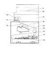
まず、この発明の第1の実施形態について図面を用いて説明する。図1および図2に、この発明による画像形成装置を示す。図1に全体の斜視図を示し、図2に、図1の装置本体の断面図を示す。
(First embodiment)
First, a first embodiment of the present invention will be described with reference to the drawings. 1 and 2 show an image forming apparatus according to the present invention. FIG. 1 shows an overall perspective view, and FIG. 2 shows a cross-sectional view of the apparatus main body of FIG.
図1および図2に示すように、この第1の実施形態による画像形成装置50においては、ホストコンピュータ(図示せず)から電装基板90に制御信号が供給される。この制御信号を受けた電装基板90の制御によってレーザスキャナ51が駆動され、これによってレーザ光が走査される。そして、プロセスカートリッジ52内に設置された感光ドラム(図示せず)に静電潜像が形成される。
As shown in FIGS. 1 and 2, in the
この静電潜像は、現像器(図示せず)によって感光ドラム上に現像され、この感光ドラム上の静電潜像は、給紙カセット53から給紙搬送されたシート材としての用紙にトナー像(図示せず)として転写される。未定着のトナーが転写された用紙は、定着手段としての定着装置54に搬送される。搬送された用紙は、定着装置54によって加熱搬送され、トナー像が定着画像として用紙上に定着される。トナーが定着された用紙はシート材積載部としての排紙トレイ55上に排出される。
The electrostatic latent image is developed on the photosensitive drum by a developing device (not shown), and the electrostatic latent image on the photosensitive drum is applied to a sheet of paper as a sheet material conveyed and fed from the
また、原稿読取手段としての原稿読取装置60は、画像形成装置50の上方に、排紙トレイ55に用紙を排出積載するための排紙空間が確保されるよう、左右の脚部、すなわち右脚70と左脚71によって支持されて設置されている。また、原稿読取装置60にはコピーボタン72が設けられている。そして、使用者(ユーザ)により、このコピーボタン72が押下されると、原稿台73に設置された原稿(図示せず)の読み込みが実行されるように構成されている。この読み込まれた画像データは、画像形成装置50に送信され、この画像形成装置50により原稿の画像が用紙上に複写形成されて出力される。なお、これらの読み込みの機構および画像形成に関する詳細は従来公知であるので、その説明を省略する。
Further, the
また、左脚71には、シート後処理手段としての電動ステープラ80または電動ステープラ80以外のシート後処理手段などが内蔵されている。電動ステープラ80以外のシート後処理手段としては例えば、孔開けを行うパンチ手段、シートの角部を丸くカットするカッター等がある。また、挿入口としてのスリット81は、電動ステープラ80に用紙を挿し込むために排紙トレイ55の上方の排紙空間に臨んで形成されている。
The
すなわち、ユーザが排紙トレイ55上にスタックされた複数枚の用紙からなるシート材束としての用紙束に対するステープル処理を所望する場合、まず、ユーザにより用紙束(図示せず)がスリット81に挿入される。これにより、電動ステープラ80が動作し、用紙束がステープル処理される。なお、電動ステープラの電源(図示せず)は、電動ステープラ80が設置されている左脚71の対向側の右脚70内に設置されている。
That is, when a user desires a stapling process for a sheet bundle as a sheet material bundle made up of a plurality of sheets stacked on the
このように構成することにより、画像形成装置の設置面積範囲内で、原稿読取装置を設置する高さを高くすることなく、ユーザが任意に使用可能な電動ステープラ80を配置することができる。すなわち、電動ステープラの電源を効率よく画像形成装置内に配置することができるので、装置全体のさらなる小型化、省スペース化を実現することができる。また、ユーザが、出力された用紙束に対して後処理を行いたい場合に任意の角に後処理を実行可能な、シート後処理装置を備えた画像形成装置を得ることができる。
With this configuration, the
(第2の実施形態)
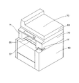
次に、この発明の第2の実施形態による画像形成装置について説明する。図3および図4に、この第2の実施形態による画像形成装置を示す。図3に、全体の斜視図を示し、図4に図3に示す装置本体を正面側からの断面図を示す。
(Second Embodiment)
Next explained is an image forming apparatus according to the second embodiment of the invention. 3 and 4 show an image forming apparatus according to the second embodiment. FIG. 3 shows a perspective view of the whole, and FIG. 4 shows a sectional view of the apparatus main body shown in FIG. 3 from the front side.
この第2の実施形態による画像形成装置50においては、図3中、操作側正面から見て、電装基板90が本体右側面の内側に配置されて設けられている。また、電動ステープラ80およびその電源(図示せず)は、電装基板90が配置されている本体右側の右脚70の中に内蔵され、正面方向に対して所定角度、この第2の実施形態においては、例えば45度傾けて設置されている。これにより、ユーザが印刷内容を確認した後にステープル処理するような場合に、最も一般的な用紙左上へのステープル処理を容易に実行することができる。
In the
以上のような構成によれば、電装基板90が画像形成装置50の側面側に設けられてい
ることにより、画像形成装置50の高さを抑制することができる。また、この構成によれば、右脚70の幅が広がるので、電動ステープラ80の向きを、用紙排出方向に対して傾けて設置可能となる。これにより、原稿読取装置60の原稿台73が高い位置に設けられることを防止するとともに、用紙束へのステープルに角度をつけ、ユーザが用紙束をめくって閲覧する場合に最適なステープルを提供することが可能となる。なお、この構成を第1の実施形態に適用しても同等の効果を得ることができる。
According to the above configuration, the height of the
また、画像形成装置50の電装基板90が、電動ステープラの設置される脚部の側面側に設置されているので、電装基板90の上方に電動ステープラを設置することができる。そのため、電動ステープラの設置自由度を向上させることができ、画像形成装置の設置面
積を増加させることなく電動ステープラの角度を傾けて、用紙の隅を綴じるのに最適な角度でステープルすることが可能となる。また、画像形成装置の設置面から原稿読取装置の原稿台高さを抑制することが可能となる。
In addition, since the
以上、この発明の実施形態について具体的に説明したが、この発明は、上述の実施形態に限定されるものではなく、この発明の技術的思想に基づく各種の変形が可能である。例えば、上述の実施形態において挙げた数値はあくまでも例に過ぎず、必要に応じてこれと異なる数値を用いてもよい。 As mentioned above, although embodiment of this invention was described concretely, this invention is not limited to the above-mentioned embodiment, The various deformation | transformation based on the technical idea of this invention is possible. For example, the numerical values given in the above embodiment are merely examples, and different numerical values may be used as necessary.
例えば、上述した第1および第2の実施形態において、印字先端方向を用紙搬送方向上流側と下流側と切り替える切り替え手段を設けることも可能である。このように、用紙への書き出し方向を上下逆にすることによって、用紙先端と電動ステープラの位置を合致させ、排紙トレイ55に積載された用紙を取り出した後、用紙の先端方向を変えることなく容易にステープル処理をさせることが可能となる。
For example, in the first and second embodiments described above, it is possible to provide switching means for switching the print leading end direction between the upstream side and the downstream side in the paper transport direction. Thus, by reversing the writing direction on the paper, the front end of the paper matches the position of the electric stapler, and after removing the paper stacked on the
また、例えば上述の第2の実施形態においては、右脚70の中に電動ステープラの電源が収められているが、必ずしもこれに限定されるものではない。例えば、電動ステープラの電源を、第1の実施形態におけると同様に、電動ステープラ80が設置されている右脚70の対向側である左脚71内に設けても、同等の効果を得ることができる。
Further, for example, in the above-described second embodiment, the electric power of the electric stapler is housed in the
50 画像形成装置
51 レーザスキャナ
52 プロセスカートリッジ
53 給紙カセット
54 定着装置
55 排紙トレイ
60 原稿読取装置
70 右脚
71 左脚
72 コピーボタン
73 原稿台
80 電動ステープラ
81 スリット
90 電装基板
DESCRIPTION OF
Claims (13)
前記原稿読取手段を、前記原稿読取手段により読み取られた画像データに基づいてシート材上に画像を形成する画像形成装置の上方に装着するための脚部と、を有し、
前記脚部は、前記原稿読取手段と、前記画像形成装置の上部に備えられたシート材積載部との間に、前記シート材積載部に前記画像形成装置からのシート材を排出積載するための排紙空間が形成されるように前記画像形成装置に装着されており、
前記脚部には、複数のシート材からなるシート材束に対して後処理を実行するシート後処理手段が備えられており、前記シート後処理手段にシート材束を挿入する挿入口が前記排紙空間に臨む側に設けられていることを特徴とする原稿読取装置。 Document reading means for reading image data on the document;
Said original reading means, anda legs for mounting above the image forming apparatus for forming an image on a sheet material based on the image data read by the original reading means,
The leg portion is for discharging and stacking the sheet material from the image forming apparatus on the sheet material stacking section between the document reading unit and the sheet material stacking section provided on the upper part of the image forming apparatus. It is attached to the image forming apparatus so that a paper discharge space is formed,
The leg portion is provided with sheet post-processing means for performing post-processing on a sheet material bundle made up of a plurality of sheet materials, and an insertion port for inserting the sheet material bundle into the sheet post-processing means is provided in the drain. An original reading apparatus provided on a side facing a paper space .
前記原稿読取手段を、前記原稿読取手段により読み取られた画像データに基づいてシート材上に画像を形成する画像形成装置の上方に装着するための脚部と、を有し、
前記脚部は、前記原稿読取手段と、前記画像形成装置の上部に備えられたシート材積載部との間に、前記シート材積載部に前記画像形成装置からのシート材を排出積載するための排紙空間が形成されるように前記画像形成装置に装着されており、
前記脚部には、複数のシート材からなるシート材束に対して後処理を実行するシート後処理手段が備えられており、前記シート後処理手段にシート材束を挿入する挿入口が装置本体の外側に向けて設けられていることを特徴とする原稿読取装置。 Document reading means for reading image data on the document;
Said original reading means, anda legs for mounting above the image forming apparatus for forming an image on a sheet material based on the image data read by the original reading means,
The leg portion is for discharging and stacking the sheet material from the image forming apparatus on the sheet material stacking section between the document reading unit and the sheet material stacking section provided on the upper part of the image forming apparatus. It is attached to the image forming apparatus so that a paper discharge space is formed,
The leg portion is provided with sheet post-processing means for performing post-processing on a sheet material bundle made up of a plurality of sheet materials, and an insertion port for inserting the sheet material bundle into the sheet post-processing means is an apparatus main body. A document reading apparatus, characterized in that the document reading apparatus is provided toward the outside of the document.
請求項1乃至4のいずれか1項記載の原稿読取装置と、An original reading apparatus according to any one of claims 1 to 4,
を備えたことを特徴とする画像形成装置。An image forming apparatus comprising:
請求項3に記載の原稿読取装置と、を備え、A document reading device according to claim 3,
前記画像形成手段を制御する電装基板が、前記シート後処理手段の設置された側と同じ側に設けられていることを特徴とする画像形成装置。An image forming apparatus, wherein an electrical board for controlling the image forming unit is provided on the same side as the side on which the sheet post-processing unit is installed.
前記原稿読取手段により読み取られた画像データに基づいてシート材上に画像を形成する画像形成手段と、
前記画像形成手段を収容する筐体上部に設けられ、シート材を積載するシート材積載部と、
前記原稿読取手段を前記シート材積載部との間に、前記シート材積載部に前記画像形成装置からのシート材を排出積載するための排紙空間が形成されるよう前記筐体上部に装着する脚部と、を有し、
前記脚部には、複数のシート材からなるシート材束に対して後処理を実行するシート後処理手段が備えられており、前記シート後処理手段にシート材束を挿入する挿入口が前記排紙空間に臨む側に設けられていることを特徴とする画像形成装置。 Document reading means for reading image data on the document;
Image forming means for forming an image on a sheet material based on image data read by the original reading means;
A sheet material stacking unit provided on an upper portion of the housing for accommodating the image forming unit and stacking sheet materials;
The document reading unit is mounted on the upper part of the housing so that a sheet discharge space for discharging and stacking sheet materials from the image forming apparatus is formed in the sheet material stacking unit between the document reading unit and the sheet material stacking unit. Legs, and
The leg portion is provided with sheet post-processing means for performing post-processing on a sheet material bundle made up of a plurality of sheet materials, and an insertion port for inserting the sheet material bundle into the sheet post-processing means is provided in the drain. An image forming apparatus provided on a side facing a paper space .
前記原稿読取手段により読み取られた画像データに基づいてシート材上に画像を形成する画像形成手段と、
前記画像形成手段を収容する筐体上部に設けられ、シート材を積載するシート材積載部と、
前記原稿読取手段を前記シート材積載部との間に、前記シート材積載部に前記画像形成装置からのシート材を排出積載するための排紙空間が形成されるよう前記筐体上部に装着する脚部と、を有し、
前記脚部は、複数のシート材からなるシート材束に対して後処理を実行するシート後処理手段が備えられており、前記シート後処理手段にシート材束を挿入する挿入口が装置本体の外側に向けて設けられていることを特徴とする画像形成装置。 Document reading means for reading image data on the document;
Image forming means for forming an image on a sheet material based on image data read by the original reading means;
A sheet material stacking unit provided on an upper portion of the housing for accommodating the image forming unit and stacking sheet materials;
The document reading unit is mounted on the upper part of the housing so that a sheet discharge space for discharging and stacking sheet materials from the image forming apparatus is formed in the sheet material stacking unit between the document reading unit and the sheet material stacking unit. Legs, and
The leg portion is provided with sheet post-processing means for performing post-processing on a sheet material bundle composed of a plurality of sheet materials, and an insertion port for inserting the sheet material bundle into the sheet post-processing means is provided in the apparatus main body. An image forming apparatus , wherein the image forming apparatus is provided facing outward .
The sheet post-processing means is a stapler, and is mounted to be inclined with respect to the sheet material discharge direction to the sheet material stacking unit in order to perform stapling with an angle with respect to the sheet material bundle. The image forming apparatus according to claim 12 .
Priority Applications (1)
| Application Number | Priority Date | Filing Date | Title |
|---|---|---|---|
| JP2006013114A JP4856956B2 (en) | 2006-01-20 | 2006-01-20 | Document reading apparatus and image forming apparatus |
Applications Claiming Priority (1)
| Application Number | Priority Date | Filing Date | Title |
|---|---|---|---|
| JP2006013114A JP4856956B2 (en) | 2006-01-20 | 2006-01-20 | Document reading apparatus and image forming apparatus |
Publications (3)
| Publication Number | Publication Date |
|---|---|
| JP2007193235A JP2007193235A (en) | 2007-08-02 |
| JP2007193235A5 JP2007193235A5 (en) | 2009-02-26 |
| JP4856956B2 true JP4856956B2 (en) | 2012-01-18 |
Family
ID=38448961
Family Applications (1)
| Application Number | Title | Priority Date | Filing Date |
|---|---|---|---|
| JP2006013114A Expired - Fee Related JP4856956B2 (en) | 2006-01-20 | 2006-01-20 | Document reading apparatus and image forming apparatus |
Country Status (1)
| Country | Link |
|---|---|
| JP (1) | JP4856956B2 (en) |
Families Citing this family (3)
| Publication number | Priority date | Publication date | Assignee | Title |
|---|---|---|---|---|
| JP4780061B2 (en) * | 2007-08-10 | 2011-09-28 | ブラザー工業株式会社 | Image forming apparatus |
| JP6312042B2 (en) * | 2014-02-17 | 2018-04-18 | 富士ゼロックス株式会社 | Image forming apparatus, binding apparatus, and binding member collection container |
| JP6858341B2 (en) * | 2016-11-22 | 2021-04-14 | 株式会社リコー | Image forming device |
Family Cites Families (10)
| Publication number | Priority date | Publication date | Assignee | Title |
|---|---|---|---|---|
| JP2550102B2 (en) * | 1987-10-09 | 1996-11-06 | 株式会社日立製作所 | Circuit breaker |
| JPH08339103A (en) * | 1995-06-12 | 1996-12-24 | Ricoh Co Ltd | Image forming device |
| JP3648427B2 (en) * | 2000-02-23 | 2005-05-18 | 京セラミタ株式会社 | Image forming apparatus |
| JP2002241033A (en) * | 2001-02-15 | 2002-08-28 | Canon Inc | Sheet handling device, and image forming apparatus having the sheet handling device |
| JP2002268307A (en) * | 2001-03-08 | 2002-09-18 | Sharp Corp | Imaging device |
| JP2003081518A (en) * | 2001-09-07 | 2003-03-19 | Canon Inc | Sheet processor and image forming device |
| JP2003081513A (en) * | 2001-09-07 | 2003-03-19 | Canon Inc | Sheet processor and image forming device |
| JP2003312870A (en) * | 2002-04-19 | 2003-11-06 | Canon Inc | Paper feeding device and image forming device |
| JP2004271896A (en) * | 2003-03-07 | 2004-09-30 | Kyocera Mita Corp | Image forming apparatus |
| JP2005115084A (en) * | 2003-10-08 | 2005-04-28 | Canon Inc | Image forming apparatus |
-
2006
- 2006-01-20 JP JP2006013114A patent/JP4856956B2/en not_active Expired - Fee Related
Also Published As
| Publication number | Publication date |
|---|---|
| JP2007193235A (en) | 2007-08-02 |
Similar Documents
| Publication | Publication Date | Title |
|---|---|---|
| JP5621680B2 (en) | Image reading device | |
| JP4462136B2 (en) | Image forming system, image forming method, and image forming program | |
| JP2007078994A (en) | Image forming apparatus | |
| JP4198118B2 (en) | Image forming apparatus | |
| JP4856956B2 (en) | Document reading apparatus and image forming apparatus | |
| JP6295948B2 (en) | Post-processing apparatus and image forming apparatus | |
| US8804206B2 (en) | Image processing device | |
| JP2009157238A (en) | Image forming apparatus | |
| JP2005115084A (en) | Image forming apparatus | |
| JP5328236B2 (en) | Sheet processing system, control method and program for sheet processing system | |
| JP2009296370A (en) | Information processor and program | |
| JP2008173937A (en) | Image forming device | |
| JP4333746B2 (en) | Copier | |
| JP2007072299A (en) | Image forming apparatus | |
| JP2006308680A (en) | Image forming apparatus | |
| JP2007011043A (en) | Image forming apparatus | |
| JP6032390B2 (en) | Image processing device | |
| JP3924514B2 (en) | Image forming apparatus | |
| JP4367434B2 (en) | Printing device | |
| JP6601370B2 (en) | Post-processing apparatus and image forming apparatus having the same | |
| JP2009120333A (en) | Sheet conveying device and image forming device | |
| JP2007067859A (en) | Image forming device having stacker provided with sample tray | |
| JP2016063371A (en) | Image reading device, image forming apparatus, control method, and program | |
| JP2007043645A (en) | Image output apparatus and method | |
| JP2005324491A (en) | Image forming apparatus |
Legal Events
| Date | Code | Title | Description |
|---|---|---|---|
| A521 | Written amendment |
Free format text: JAPANESE INTERMEDIATE CODE: A523 Effective date: 20090109 |
|
| A621 | Written request for application examination |
Free format text: JAPANESE INTERMEDIATE CODE: A621 Effective date: 20090109 |
|
| A131 | Notification of reasons for refusal |
Free format text: JAPANESE INTERMEDIATE CODE: A131 Effective date: 20110531 |
|
| A977 | Report on retrieval |
Free format text: JAPANESE INTERMEDIATE CODE: A971007 Effective date: 20110601 |
|
| A521 | Written amendment |
Free format text: JAPANESE INTERMEDIATE CODE: A523 Effective date: 20110729 |
|
| TRDD | Decision of grant or rejection written | ||
| A01 | Written decision to grant a patent or to grant a registration (utility model) |
Free format text: JAPANESE INTERMEDIATE CODE: A01 Effective date: 20111025 |
|
| A01 | Written decision to grant a patent or to grant a registration (utility model) |
Free format text: JAPANESE INTERMEDIATE CODE: A01 |
|
| A61 | First payment of annual fees (during grant procedure) |
Free format text: JAPANESE INTERMEDIATE CODE: A61 Effective date: 20111031 |
|
| FPAY | Renewal fee payment (event date is renewal date of database) |
Free format text: PAYMENT UNTIL: 20141104 Year of fee payment: 3 |
|
| FPAY | Renewal fee payment (event date is renewal date of database) |
Free format text: PAYMENT UNTIL: 20141104 Year of fee payment: 3 |
|
| LAPS | Cancellation because of no payment of annual fees |