JP4856574B2 - 2-piece oil ring wire and 2-piece oil ring - Google Patents
2-piece oil ring wire and 2-piece oil ring Download PDFInfo
- Publication number
- JP4856574B2 JP4856574B2 JP2007073822A JP2007073822A JP4856574B2 JP 4856574 B2 JP4856574 B2 JP 4856574B2 JP 2007073822 A JP2007073822 A JP 2007073822A JP 2007073822 A JP2007073822 A JP 2007073822A JP 4856574 B2 JP4856574 B2 JP 4856574B2
- Authority
- JP
- Japan
- Prior art keywords
- oil
- oil ring
- ring
- shape
- piece
- Prior art date
- Legal status (The legal status is an assumption and is not a legal conclusion. Google has not performed a legal analysis and makes no representation as to the accuracy of the status listed.)
- Expired - Fee Related
Links
Images

Description
本願発明は、内燃機関の2ピースオイルリング用線材に関する。 The present invention relates to a two-piece oil ring wire for an internal combustion engine.
従来から、往復動内燃機関においては、燃焼ガスや潤滑オイルのシールのために、ピストンリングが用いられている。ピストンリングには燃焼ガスをシールする圧力リングとオイルをシールするオイルリングがあり、更に、オイルリングには主にガソリンを燃料とするエンジンに使われる3ピースオイルリングと呼ばれるものと、軽油を燃料とするディーゼルエンジンに使われる2ピースオイルリングと呼ばれるものがある。両者とも内周側から板状或いはコイル状バネによりシリンダ内面に上下レール摺動面部が一定の接触圧力で接触して、上下レール間の潤滑油をシリンダ内面に塗布すると共に、余剰の潤滑オイルを掻き落し、適切な油膜を形成する役割をなしている。しかしながら、自動車ガソリンエンジンの低燃費化の要請から、3ピ−スオイルリングではピストン軸方向厚さを薄幅にする方向にあり、その結果、従来の3ピースオイルリングではオイルコントロール性能が不十分となってきており、ガソリンエンジンにも2ピースオイルリングが使われるようになってきている。 Conventionally, in a reciprocating internal combustion engine, a piston ring is used for sealing a combustion gas or lubricating oil. The piston ring has a pressure ring that seals the combustion gas and an oil ring that seals the oil. The oil ring is a so-called three-piece oil ring that is mainly used in engines that use gasoline as fuel. There is a so-called two-piece oil ring used in diesel engines. In both cases, the upper and lower rail sliding surfaces are brought into contact with the inner surface of the cylinder by a plate or coil spring from the inner peripheral side at a constant contact pressure, and the lubricating oil between the upper and lower rails is applied to the inner surface of the cylinder, and excess lubricating oil is applied. It plays the role of scraping off and forming an appropriate oil film. However, due to the demand for lower fuel consumption of automobile gasoline engines, the three-piece oil ring is in the direction of reducing the piston axial thickness, and as a result, the conventional three-piece oil ring has insufficient oil control performance. As a result, two-piece oil rings are also used in gasoline engines.
2ピースオイルリングはシリンダ内面と摺動するレール部とそれをつなぐ柱部(以後、ウェブ)から成る略M字型の本体とその本体を内周側から拡張するためのコイル状バネの2つで構成される。従来の2ピースオイルリング本体は、鋳鉄から加工により略M字型に削りだし、上下方向の中間部のウェブに切削により通油孔が形成されていた。しかしながら、近年、エンジンの高性能化に伴い、オイルンリングも高強度が望まれるようになり、2ピースオイルリングも鋳鉄製から鋼製に置換されるに至った。その結果、線材メーカーにおいて、丸線素材を焼鈍・圧延を繰り返し行い、略M字型の異形線材とした後、ウェブに穿孔により通油孔を設け、熱処理によって硬化する。その後、ピストンリングメーカーにより、コイリング、切断、外周加工、表面処理加工等が行われ2ピースオイルリング本体が作られるように成ってきている。 The two-piece oil ring has two parts, a substantially M-shaped main body composed of a rail portion that slides on the cylinder inner surface and a column portion (hereinafter referred to as a web) connecting the inner surface and a coil spring for expanding the main body from the inner peripheral side. Consists of. The conventional two-piece oil ring main body has been machined from cast iron into a substantially M-shape by machining, and an oil passage hole is formed in the intermediate web in the vertical direction by cutting. However, in recent years, as the performance of the engine has been improved, the oil ring has also been required to have high strength, and the two-piece oil ring has been replaced from cast iron by steel. As a result, in a wire manufacturer, a round wire material is repeatedly annealed and rolled to form a substantially M-shaped deformed wire, and then an oil passage hole is provided in the web by perforation and cured by heat treatment. Thereafter, the piston ring maker performs coiling, cutting, outer periphery processing, surface treatment processing, and the like to form a two-piece oil ring main body.
オイルリングは潤滑オイルのシールという役割から圧力リングに比べその面圧は数倍という高さに設定されていたが、自動車エンジンの低燃費化にあっては、オイルリングの摩擦力の低減が重要となってきており、面圧を下げる方向にある。しかしながら、一方では、一層のオイル消費の低減も求められて来ている。このようなことから、2ピースオイルリング外周摺動面の形状を見直すことが行われるように成ってきた。何故なら、4サイクル往復動内燃機関はピストンがシリンダ内周面を単に往復動するのであるが、吸気、圧縮、燃焼、排気という異なった4工程を1サイクルとするものであり、ピストンリングにあっては、その各工程で求められる機能も異なるものである。従って、従来のように、ピストン運動方向(ピストンリング上下方向)に対称な形状を有する必要はなく、上記各工程に適した形状が望ましいと思われるに至った。 The surface pressure of the oil ring has been set several times higher than that of the pressure ring due to the role of the seal of the lubricating oil. However, reducing the frictional force of the oil ring is important in reducing the fuel consumption of automobile engines. It is in the direction of lowering the surface pressure. However, on the other hand, further reduction in oil consumption has been demanded. For this reason, it has become possible to review the shape of the outer peripheral sliding surface of the two-piece oil ring. This is because in a 4-cycle reciprocating internal combustion engine, the piston simply reciprocates on the inner peripheral surface of the cylinder, but four different steps of intake, compression, combustion, and exhaust are considered as one cycle, The functions required in each process are also different. Therefore, it is not necessary to have a symmetrical shape in the piston movement direction (piston ring vertical direction) as in the prior art, and it seems that a shape suitable for each of the above steps is desirable.
このような2ピースオイルリングとして、例えば、特開平9−144881号には、ピストン上昇工程時の潤滑オイル掻き作用を抑制し、潤滑オイル消費量を低減する組合せオイルリングの形状として、ピストンリングの上下レールの外周摺動面が、シリンダ内周面と摺動する当り面と、当り面の上方に配置し当り面から離れるに従って径が小さくなるテーパ面とからなる構造としている。即ち、このようなオイルリングにあっては、ピストンリングの上昇時には、テーパ面によって油膜に乗り上げやすくなり、レール摺動面の潤滑オイル掻き上げ作用が抑制されると同時に摺動抵抗を低減することが出来る。又、ピストンリング下降時には摺動面下側のエッジでオイル掻き下げ能力が向上し、潤滑オイル消費量が低減するとしている。 As such a two-piece oil ring, for example, in Japanese Patent Laid-Open No. 9-144881, the shape of a combined oil ring that suppresses the lubricating oil scraping action during the piston ascending process and reduces the amount of lubricating oil consumption, The outer peripheral sliding surface of the upper and lower rails has a contact surface that slides with the inner peripheral surface of the cylinder, and a tapered surface that is disposed above the contact surface and has a diameter that decreases as the distance from the contact surface increases. That is, in such an oil ring, when the piston ring is lifted, it becomes easy to ride on the oil film by the tapered surface, and the sliding action of the lubricating oil on the rail sliding surface is suppressed and at the same time the sliding resistance is reduced. I can do it. Further, when the piston ring is lowered, the oil scraping ability is improved at the lower edge of the sliding surface, and the amount of lubricating oil consumption is reduced.
このように、オイルリングの性能の向上を考えた場合、2ピースオイルリングにあっては、レール外周摺動面形状がピストンリング上下方向で非対称となる2ピースオイルリングが作られるようになってきた。このような中、回収した潤滑オイルの通り道である通油孔形状を見直すことも行われてきている。 In this way, when considering the improvement in the performance of the oil ring, in the case of a two-piece oil ring, a two-piece oil ring is formed in which the rail outer peripheral sliding surface shape is asymmetric in the piston ring vertical direction. It was. Under such circumstances, it has also been carried out to review the shape of the oil passage hole that is the path of the recovered lubricating oil.
特開昭63−277844号は、オイルリングの強度を損なうことのない通油孔の形状として、楕円形あるいは菱形にすることにより、通油孔の縁の周辺における断面二次モーメントの変化を緩やかにすることができ、オイルリングが曲げられた時に生じる膨出を小さくすることができることを開示するものである。 Japanese Patent Application Laid-Open No. 63-277844 discloses that the shape of the oil passage hole that does not impair the strength of the oil ring is made oval or rhombus so that the change in the secondary moment of inertia around the edge of the oil passage hole is moderated. It is disclosed that bulging that occurs when the oil ring is bent can be reduced.
特開2006−22903号は、オイルリング軸方向高さが薄いオイルリングの強度を損なうことなく通油孔の面積を確保することが可能なオイルリングを提供することを目的としたもので、通油孔は、両端部に向き合うように配置された2つの円弧と、上記弧部の幅よりも広い幅方向の距離を有するように配置された2つの平行直線部と、上記弧部と上記平行直線部とを結ぶ斜行部とを有するものである。 Japanese Patent Application Laid-Open No. 2006-22903 is intended to provide an oil ring capable of securing the area of the oil passage hole without impairing the strength of the oil ring having a thin oil ring axial height. The oil hole includes two arcs arranged so as to face both ends, two parallel straight parts arranged to have a distance in the width direction wider than the width of the arc part, and the arc part and the parallel part. And a skewed portion connecting the straight line portion.
特開2003−286899号は、ピストンのオイル戻し孔から燃焼ガスが漏れることを防止することが出来る2ピースオイルリングとして、ピストンリングに形成される通油孔がオイルリング下側のレールを貫通してオイルリング下側面に通じていることを特徴とする2ピースオイルリング本体を開示する。 Japanese Patent Laid-Open No. 2003-286899 discloses a two-piece oil ring that can prevent combustion gas from leaking from an oil return hole of a piston, and an oil passage hole formed in the piston ring penetrates a rail below the oil ring. A two-piece oil ring main body characterized in that it communicates with the lower surface of the oil ring.
特開2006−194272号は、オイルの通油性に優れたオイルリングに用いられる2ピースオイルリング用線材に関するもので、そのオイル通油孔の開口面積がオイルリング外周側よりもオイルリング内周側が大きくなるように、オイルリ通油孔の側壁の少なくとも一方が傾斜しているオイルリング用線材を開示する。 Japanese Patent Application Laid-Open No. 2006-194272 relates to a two-piece oil ring wire used for an oil ring excellent in oil permeability. The oil ring has an opening area on the inner side of the oil ring rather than the outer side of the oil ring. An oil ring wire is disclosed in which at least one of the side walls of the oil passage hole is inclined so as to be larger.
以上のように、2ピースオイルリングにおいては、通油孔形状に関する特許が数多く出願されているが、オイルリング上下方向で対称な形状の通油孔を持つものばかりであり、通油孔から、その上下方向を容易に判別できるものは無かった。 As described above, in the two-piece oil ring, many patents relating to the oil passage hole shape have been filed. However, the oil ring has only oil passage holes that are symmetrical in the vertical direction of the oil ring. There was nothing that could easily distinguish the vertical direction.
ところで、ピストンリング上下方向に非対称である外周摺動面形状を持つことを特徴とする2ピースオイルリング、例えば前記特開平9−144881号のようなオイルリングにあっては、その機能を発揮するためには、狙いとした方向でピストンに組付けされる必要があることは言うまでもない。従って、ピストンにピストンリングを組付ける時、ピストンリングの上下方向を正しく組むことが重要となる。上下方向を誤って組付けた場合、本来の目的とは違った働きとなるので、前記の潤滑オイル消費量の低減が行えず、却って、潤滑オイル消費量の悪化、摺動抵抗の増大をもたらすことになる。 By the way, a two-piece oil ring having an outer peripheral sliding surface shape that is asymmetric in the vertical direction of the piston ring, for example, an oil ring such as that disclosed in JP-A-9-144881, exhibits its function. In order to achieve this, it goes without saying that the piston needs to be assembled in the intended direction. Therefore, when assembling the piston ring to the piston, it is important to correctly assemble the piston ring in the vertical direction. If the vertical direction is assembled incorrectly, it will work differently from the original purpose, so it will not be possible to reduce the above-mentioned lubricating oil consumption, but rather deteriorate the lubricating oil consumption and increase the sliding resistance. It will be.
ところが、このような従来の2ピースオイルリングにあっては上下レール部のシリンダとの接触面は極微細加工面であるので、目視でこの摺動面から2ピースオイルリングの上下方向の判別は非常に困難である。従って、上下方向を誤ってピストンに組付けること(以後、誤組)が発生した。そのため、ピストンリング製造メーカーと自動車メーカーとの間で誤組を防止するために、ピストンリングの合い口の一方側に標識を付ける等の取り決めを行い誤組の発生を防止している。
しかしながら、ピストンリング製造メーカーからピストンリングの組付けが行われる所へピストンリングを搬送する時には防錆油等を付けることが行われるので、この標識が消える可能性がある。又、標識を付ける前には、ピストンリング製造メーカーで上下方向判別を行う必要があるが、上記の理由で、この判別作業が容易とは言えない。そのため、これら2ピースオイルリングの生産コスト的は高いものとなっており、このような方向性のあるオイルリングの普及の妨げとなっていた。
However, in such a conventional two-piece oil ring, the contact surface of the upper and lower rails with the cylinder is a micro-machined surface, so that the vertical direction of the two-piece oil ring can be visually determined from this sliding surface. It is very difficult. Accordingly, the piston was erroneously assembled to the piston in the vertical direction (hereinafter erroneous assembly). For this reason, in order to prevent erroneous assembly between the piston ring manufacturer and the automobile manufacturer, an arrangement such as attaching a mark to one side of the joint of the piston ring is performed to prevent the occurrence of erroneous assembly.
However, when the piston ring is transported from the piston ring manufacturer to the place where the piston ring is assembled, rust preventive oil or the like is applied, so this sign may disappear. In addition, it is necessary for the piston ring manufacturer to determine the vertical direction before attaching the mark, but for the above reason, this determination operation is not easy. For this reason, the production cost of these two-piece oil rings is high, which hinders the spread of such directional oil rings.
即ち、オイルリング外周摺動面を上下方向に方向性のある摺動面を設けた2ピースオイルリングにあっては、その後、前記標識を付けるためにも、方向性を容易に判別可能な2ピースオイルリングが望ましく、更に、標識を設けずとも容易に方向判別が出来る2ピースオイルリングが一層望ましいと言える。 That is, in the two-piece oil ring in which the oil ring outer peripheral sliding surface is provided with a sliding surface having directionality in the vertical direction, the directionality can be easily discriminated for attaching the mark 2 A piece oil ring is desirable, and a two-piece oil ring that can easily determine the direction without providing a sign is more desirable.
本願発明は上記問題点に鑑みてなされたものであり、2ピースオイルリングの上下レール部の外周摺動面形状に方向性を持たせた2ピースオイルリングの製造に於いて、これら方向性が容易に判別可能な2ピースオイルリング用線材を提供することを目的とするものである。 The present invention has been made in view of the above problems, and in the production of a two-piece oil ring in which the outer peripheral sliding surface shape of the upper and lower rail portions of the two-piece oil ring has a direction, An object of the present invention is to provide a two-piece oil ring wire that can be easily discriminated.
本願発明では上記課題を解決するために次の手段を用いる。
本願第一の発明は、油掻きを目的とした上下レール(10、11)とそれをつなぐウェブ(15)とからなり、前記ウェブ(15)には、複数の通油孔(2)が設けられている2ピースオイルリング用線材において、前記通油孔(2)は、上下レール方向で一方向に揃えられた非対称形状の通油孔を含むことを特徴とする2ピースオイルリング用線材である。また、本願第二の発明は、上下レール方向で非対称形状の通油孔が略台形又は略三角形の形状であることを特徴とする本願第一の発明の2ピースオイルリング用線材である。
In the present invention, the following means are used to solve the above problems.
The first invention of the present application comprises an upper and lower rail (10, 11) for the purpose of oil scraping and a web (15) connecting the upper and lower rails (10, 11). The web (15) is provided with a plurality of oil passage holes (2). In the two-piece oil ring wire, the oil passage hole (2) includes an asymmetrical oil passage hole aligned in one direction in the upper and lower rail directions. is there. The second invention of the present application is the two-piece oil ring wire according to the first invention of the present application, wherein the oil passage holes having an asymmetric shape in the vertical rail direction are substantially trapezoidal or triangular.
ここで、通油孔(2)が「上下レール方向で非対称形状」とは、2ピースオイルリング用線材をレール摺動面側から見た時に通油孔の平面形状が上下レールの上下方向中心線に対して線対称ではないことを意味する。 Here, the oil passage hole (2) is “asymmetrical shape in the vertical rail direction” means that the planar shape of the oil passage hole is the center in the vertical direction of the vertical rail when the two-piece oil ring wire is viewed from the rail sliding surface side. Means not line symmetric with respect to the line.
又、ここで云う「上下レール方向で一方向に揃えられた」とは、略台形又は略三角形等の非対称な形状の通油孔が2ピースオイルリング用線材の線材方向に移動した如く、同じ方向を向いた形をしていること意味する。例えば、非対称な形状が略三角形の場合では、その底辺が2ピースオイルリング用線材の一方のレール側に有ることで揃っている通油孔であることを意味する。 In addition, the term “aligned in one direction in the upper and lower rail direction” as used herein means that the oil passage hole having an asymmetric shape such as a substantially trapezoidal shape or a substantially triangular shape moves in the direction of the wire of the two-piece oil ring wire. It means that the shape is facing the direction. For example, when the asymmetrical shape is a substantially triangular shape, it means that the bottom side is an oil passage hole that is aligned by being on one rail side of the two-piece oil ring wire.
又、更に、ここで言う「略台形」とは上下方向の辺の長さが異なるものであって、図形の上下方向が判別できる程度のもので良く、数学的な台形を意味するものではない。従って、通油孔のオイルリング周方向の両辺が曲線であるものも含まれる。「略三角形」は三辺で形成されていて、上下方向が判別できるものをいう。尚、両形状とも、各辺の交点が曲線であるものも含まれる。 Furthermore, the “substantially trapezoidal shape” mentioned here has different lengths in the vertical direction, and can be determined so that the vertical direction of the figure can be distinguished, and does not mean a mathematical trapezoid. . Accordingly, the oil permeation hole includes both curved sides of the oil ring in the circumferential direction. The “substantially triangular” is formed of three sides and can distinguish the vertical direction. Note that both shapes include those in which the intersection of each side is a curve.
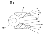
図1は上レール(10)の外周摺動面形状(12)がレール外周面の軸方向中心より軸方向下寄りを頂点として、軸方向上方に縮径したテーパ面で形成され、上レール上斜面(14)につながっており、下レール(11)の外周摺動面(12)も上レールの外周面と同様に、下レール外周面の軸方向中心より軸方向下寄りを頂点として、軸方向上方に縮径したテーパ面で形成され、下レール上面(16)につながっているように構成されている2ピースオイルリングである。このような2ピースオイルリングでは、その外周摺動面形状の目的とする効果を発揮させるには、ピストンに2ピースオイルリングを組付ける際に、上記のようにピストンリングを組付けなければならない。しかしながら、従来の2ピースオイルリングに有っては、上下方向の判別は前記外周摺動面(12)の形状から判別するほかなく、ピストンリング全加工が終了後に判別装置を用いて判別し、自動車メーカーでの組付け時に上下方向が判るように標識を付けていた。しかしながら、この標識も消えることが多く確実なものとは言えなかった。 FIG. 1 shows that the outer rail sliding surface shape (12) of the upper rail (10) is formed by a tapered surface whose diameter is reduced upward in the axial direction with the lower side in the axial direction as the apex from the axial center of the rail outer peripheral surface. Like the outer peripheral surface of the upper rail, the outer peripheral sliding surface (12) of the lower rail (11) is connected to the slope (14). It is a two-piece oil ring that is formed with a tapered surface that is reduced in diameter in the upper direction and is connected to the upper surface (16) of the lower rail. In such a two-piece oil ring, the piston ring must be assembled as described above when assembling the two-piece oil ring to the piston in order to exert the desired effect of the outer peripheral sliding surface shape. . However, in the conventional two-piece oil ring, the vertical direction is determined by determining the shape of the outer peripheral sliding surface (12), and is determined by using a determination device after the piston ring is completely processed. At the time of assembly at an automobile manufacturer, a sign was attached so that the vertical direction could be understood. However, this sign often disappears and could not be said to be reliable.
そこで、本願発明では2ピースオイルリングを外周レール側から、通油孔の形状を見ることで上下方向判別ができるように、2ピースオイルリング用線材の穿孔の段階で上下方向に非対称な形状の通油孔を設けておき、上下レール外周摺動面に方向性のある加工を行う時に、通油孔形状を拠り所に、前もって決めておいた方向に合わせて加工する。このように加工すると、後工程で上下方向が不揃いになっても、最終段階での方向合わせを目視又は自動判別機で容易に行えるし、ピストンへのオイルリング組付け時に於いても、組付け機に上下方向を間違えることなく取り付けることができるから、誤組を解消することが出来る。 Therefore, in the present invention, the two-piece oil ring has an asymmetric shape in the vertical direction at the stage of drilling the wire for the two-piece oil ring so that the vertical direction can be determined by looking at the shape of the oil passage hole from the outer rail side. When an oil passage hole is provided and a directional process is performed on the outer peripheral sliding surface of the upper and lower rails, machining is performed in accordance with a predetermined direction based on the shape of the oil passage hole. If processed in this way, even if the vertical direction becomes uneven in the subsequent process, the final direction can be easily aligned visually or with an automatic discriminator, and can be assembled even when the oil ring is assembled to the piston. Since it can be attached to the machine without making a mistake in the vertical direction, it is possible to eliminate misassembly.
以下、本願発明の内燃機関用2ピースオイルリング用線材について図面を用いて具体的に説明する。 Hereinafter, the wire material for a two-piece oil ring for an internal combustion engine of the present invention will be specifically described with reference to the drawings.
図2は本願発明に係る2ピースオイルリング用線材(a)(b)及び従来の2ピースオイルリング用(c)線材をピストンリングの外周面側となるレール側から見た平面図である。上下レール(10,11)に挟まれたウェブ(15)に複数の通油孔が設けられている。図2(a)の2ピースオイルリング用線材は、通油孔が上下レール方向で非対称形状の一形態である略台形の通油孔(2a)と上下レール方向で対称形状の一形態である略長円の通油孔(2c)から成るものである。前記非対称形状の略台形の通油孔(2a)は、上レール側の長直線(3)と下レール側の短直線(4)と前記長直線及び前記短直線の左端部を結ぶ左辺(5)と前記長直線及び前記短直線の右端部を結ぶ右辺(6)から成るものであり、上レール側を長辺とする一方向に揃えられている。この例では、1つの略台形の通油孔と1つの略長円の通油孔が繰り返されて形成されている。 FIG. 2 is a plan view of the two-piece oil ring wire (a) and (b) according to the present invention and the conventional two-piece oil ring (c) wire as viewed from the rail side which is the outer peripheral surface side of the piston ring. A plurality of oil passage holes are provided in the web (15) sandwiched between the upper and lower rails (10, 11). The wire for a two-piece oil ring in FIG. 2 (a) has a substantially trapezoidal oil passage hole (2a) in which the oil passage hole is one form of an asymmetric shape in the upper and lower rail directions and one form symmetrical to the upper and lower rail directions. It consists of a substantially oval oil passage hole (2c). The asymmetrical substantially trapezoidal oil passage hole (2a) includes a long straight line (3) on the upper rail side, a short straight line (4) on the lower rail side, a left side (5) connecting the long straight line and the left end of the short straight line. ) And the right side (6) connecting the long straight line and the right end of the short straight line, and aligned in one direction with the upper rail side as the long side. In this example, one substantially trapezoidal oil passage hole and one substantially oval oil passage hole are formed repeatedly.
ここで、図2(a)は本発明の一実施形態であり、本発明はこれに限定されるものではなく、上下レール方向非対称な形状としては、前記略台形以外に、三角形(2b)、平行四辺形等を用いることが出来る。又、上下レール方向対称な形状としては、円、楕円、長円、正方形、長方形等を用いることが出来る。又、上下レール方向非対称な形状の通油孔は上下レール方向対称な形状の通油孔1から5個置きに繰り返し形成されている。尚、ピストンリングに成形した場合には、ピストンリング周方向両端が前記通油孔に掛かることがあるので、この限りではない。 Here, FIG. 2 (a) is an embodiment of the present invention, and the present invention is not limited to this, and as an asymmetric shape in the vertical rail direction, in addition to the substantially trapezoidal shape, the triangle (2b), A parallelogram or the like can be used. In addition, as a shape symmetric with respect to the upper and lower rails, a circle, an ellipse, an ellipse, a square, a rectangle, or the like can be used. In addition, the oil passage holes having an asymmetric shape in the upper and lower rail directions are repeatedly formed at intervals of five from the oil passage holes 1 having a symmetrical shape in the upper and lower rail directions. In addition, when it shape | molds to a piston ring, since the piston ring circumferential direction both ends may be applied to the said oil passage hole, it is not this limitation.
次に、本願発明の2ピースオイルリング線材の製造方法について述べる。本願発明の2ピースオイルリングは冷間引抜き法或いはロールダイスの温間加工法にてより製造する異形線材であり、上下レール(10,11)の外周摺動面形状が、非対称の2ピースオイルリングに用いられることが好ましく、線材の両レール外周摺動面形状を目的とする方向性もったものに近い形状に成形することで加工量低減が図られ望ましいが、この非対称外周摺動面形状は外周摺動面加工時に本願発明の通油孔の方向性を目安に加工することも出来るので、特にそのような線材である必要はない。尚、通油孔形状の方向性と外周摺動面形状の方向性には望ましい関係があるとも考えられるが、上記の通り、外周摺動面加工は通油孔の方向性に合わせ加工することも出来るのでここで限定しない。 Next, a method for producing a two-piece oil ring wire according to the present invention will be described. The two-piece oil ring of the present invention is a deformed wire manufactured by a cold drawing method or a hot working method of a roll die, and the outer peripheral sliding surface shape of the upper and lower rails (10, 11) is an asymmetric two-piece oil. It is preferably used for rings, and it is desirable to reduce the amount of processing by forming the shape of both rail outer peripheral sliding surfaces of the wire rod to a shape close to the desired directionality. Can be processed with reference to the directionality of the oil passage hole of the present invention at the time of processing the outer peripheral sliding surface, and it is not necessary to use such a wire. Although it is considered that there is a desirable relationship between the direction of the oil passage hole shape and the direction of the outer peripheral sliding surface shape, as described above, the outer peripheral sliding surface machining should be performed according to the direction of the oil passage hole. It is not limited here.
まず、スチール素材を熱間圧延後焼鈍したコイル材の表面疵を除去した後、温間伸線によりオイルリング本体寸法にあった線径にし、四方ロールにより長方形断面の平角線材にする。これを温間及び冷間での孔型ロールダイスによる連続異形ロール加工を施し、本願発明の2ピースオイルリング用の異形線材を得る。通油孔の形成は、一般的には、打ち抜きパンチにより形成される。その後、焼入れ焼戻しを行い、2ピースオイルリング用線材にする。打抜き穿孔では、複数の並べられた打抜きパンチで穿孔し、同時に複数の通油孔を作製する。従って、そのパンチの一部又は全部を上下方向に非対称の形状が打抜けるパンチとし、残りを上下方向対称な通油孔が打抜けるパンチとすれば、非対称形状の通油孔と対称形状の通油孔が規則的に周期的に配列した線材を得ることが出来る。このように、2ピースオイルリング用線材を作ると、2ピースオイルリングに成形してからも、形成した上下方向非対称な通油孔があるパターンで両端を除き、繰り返しで一視野内に現れるから、2ピースオイルリングの上下の方向性を容易に確認できる。 First, after removing the surface flaws of the coil material that has been annealed after hot rolling the steel material, the wire diameter matches the oil ring body size by warm drawing, and a rectangular wire having a rectangular cross section is formed by a four-way roll. This is subjected to continuous deformed roll processing with a hot and cold perforated roll die to obtain a deformed wire for a two-piece oil ring of the present invention. The oil passage hole is generally formed by a punching punch. Thereafter, quenching and tempering are performed to obtain a two-piece oil ring wire. In punching and punching, punching is performed with a plurality of arranged punching punches, and a plurality of oil passage holes are formed at the same time. Therefore, if a part or all of the punch is a punch through which an asymmetric shape is punched in the vertical direction, and the other punch is a punch through which an oil passage hole that is symmetrical in the vertical direction is punched, the asymmetrical oil passage hole and the symmetrical passage are provided. A wire rod in which oil holes are regularly and periodically arranged can be obtained. In this way, when a wire for a two-piece oil ring is made, even if it is formed into a two-piece oil ring, it will appear in one field of view repeatedly, excluding both ends in a pattern with the formed asymmetric oil passage holes in the vertical direction. The vertical direction of the two-piece oil ring can be easily confirmed.
本願発明の2ピースオイルリング線材は、外周摺動面に硬質クロムめっき皮膜やイオンプレーティング皮膜を設け使用される軟鋼線材やガス窒化層、塩浴窒化層等を形成して使用される耐摩耗性や耐熱性向上に富むマルテンサイト系ステンレス鋼等の高合金鋼の素材から成形されるので穿孔には打抜きパンチによる穿孔が行われてきたが、近頃は、オイルリングの薄幅化に伴い通油孔が微細になってきたことから、打抜きパンチによる穿孔のほか、レーザーや電子ビーム等を用い、通油孔を形成することも行われるようになってきている。 The two-piece oil ring wire of the present invention is a wear-resistant material used by forming a mild steel wire, gas nitrided layer, salt bath nitrided layer, etc. to be used by providing a hard chromium plating film or ion plating film on the outer peripheral sliding surface Since it is formed from a material of high alloy steel such as martensitic stainless steel, which has a lot of improvement in heat resistance and heat resistance, punching has been carried out by punching, but recently, as oil rings have become thinner, Since the oil holes have become finer, in addition to punching with a punching punch, the formation of oil passage holes using a laser, an electron beam, or the like has come to be performed.
本願第二の発明においては上下方向非対称の通油孔の形状を略台形又は略三角形にする。略台形の通油孔は従来の長円や四角形状の通油孔と比べてもオイル通過性能や上下方向の強度の低下が少ないので非対称の通油孔として好ましい。略台形の角や軸方向辺を円弧状にすれば、断面モーメントの変化も小さくなるのでより好ましい。略三角形とすると視認性が良くなり、誤った組付け等の恐れが一層少なくできる。尚、三角形形状とした場合は、穿孔でのパンチの寿命やリング強度等から、底辺の長い三角形が望ましい。 In the second invention of the present application, the shape of the oil passage hole which is asymmetric in the vertical direction is substantially trapezoidal or triangular. The substantially trapezoidal oil passage hole is preferable as an asymmetric oil passage hole because the oil passage performance and the strength in the vertical direction are less deteriorated than the conventional oval or square oil passage hole. If the substantially trapezoidal corners and the sides in the axial direction are formed in an arc shape, the change in the cross-sectional moment is reduced, which is more preferable. When the triangular shape is used, the visibility is improved and the risk of incorrect assembly can be further reduced. In the case of a triangular shape, a triangle having a long bottom is desirable from the viewpoint of punch life in drilling, ring strength, and the like.
なお、本願発明は、上記実施形態に限定されるものではない。本願発明の特許請求の範囲に記載された技術的思想と実質的に同一な構成を有し、同様な作用効果を奏するものは、いかなるものであっても本願発明の技術的範囲に包含される。 In addition, this invention is not limited to the said embodiment. Any device that has substantially the same configuration as the technical idea described in the claims of the present invention and that exhibits the same effect is included in the technical scope of the present invention. .
以下に実施例および比較例を示して本願発明をさらに具体的に説明する。
[実施例1]
素材材質がC:0.85、Si:0.35、Mn:0.30、P:0.03、S:0.02、Cr:18.0、Mo:1.25、V:0.10、Fe:残部(質量%)(JIS SUS440B相当)のスチール丸線を熱間圧延後焼鈍し、更に、コイル材の表面疵を除去した後、温間伸線によりオイルリング本体寸法にあったφ5.5mmにした。これを四方ロールにより長方形断面の平角線材にし、温間及び冷間での孔型ロールダイスによる連続異形ロール加工を施し2ピースオイルリング用の異形線材を得る。通油孔の形成は、打ち抜きパンチにより形成した。打抜きパンチは5穴を同時に穿孔するもので、その中央のパンチを略台形の形状が打ち抜けるものにし、他は従来の長円形状が打抜けるものにした。その後、焼入れ焼戻しを行い、上下方向幅が1.5mm、内外径厚さが1.5mmの2ピースオイルリング用線材を得た。通油孔の形状は、略台形と長円であり、略台形が2個に長円が3個の割合で配置されているものである。
The present invention will be described more specifically with reference to the following examples and comparative examples.
[Example 1]
The material is C: 0.85, Si: 0.35, Mn: 0.30, P: 0.03, S: 0.02, Cr: 18.0, Mo: 1.25, V: 0.10 , Fe: Remaining (mass%) (JIS SUS440B equivalent) steel round wire was annealed after hot rolling, and after removing surface flaws of the coil material, it was φ5 which was in the oil ring body size by warm drawing 5 mm. This is converted into a rectangular wire having a rectangular cross section by a four-way roll, and subjected to continuous deformed roll processing by a hot and cold perforated roll die to obtain a deformed wire for a two-piece oil ring. The oil passage hole was formed by a punching punch. The punching punch was made by punching 5 holes at the same time. The punch in the center of the punching punch was punched out in a substantially trapezoidal shape, and the others were punched out in a conventional oval shape. Thereafter, quenching and tempering were performed to obtain a two-piece oil ring wire having a vertical width of 1.5 mm and an inner and outer diameter thickness of 1.5 mm. The shape of the oil passage hole is a substantially trapezoid and an ellipse, and two substantially trapezoids are arranged in a ratio of three ellipses to two.
この線材を、外径が75.0mmになるようにピストンリング用コイリング装置により成形し、コイリング状態のものをある程度外周摺動面に近似した形状に砥石加工を行い、切断、その後、熱処理で成形時の応力の除去を行い、さらに、表面処理としてガス窒化層を形成した。その後、レール外周摺動面を砥石加工により、レールの外周摺動面形状がピストン軸方向中心からピストン軸方向下寄りを頂点とした非対称形状から形成され上レール上面につながっており、下レールの外周摺動面も上レールの外周面と同様に、下レールのピストン軸方向からピストン軸方向下寄りを頂点とした非対称形状から形成され、下レール下面につながっているように構成されている方向性のある外周摺動面形状を作成した。次に、リング合口部を整え、本体の高さh1が1.5mmになるように側面の加工を施すという工程で2ピースオイルリング本体を製造した。 This wire is molded by a coiling device for piston ring so that the outer diameter becomes 75.0 mm, and the coiled one is grinded into a shape that approximates the outer peripheral sliding surface to some extent, cut, and then molded by heat treatment The stress at the time was removed, and a gas nitride layer was formed as a surface treatment. After that, the outer peripheral sliding surface of the rail is processed with a grinding wheel so that the shape of the outer peripheral sliding surface of the rail is formed as an asymmetrical shape with the lower side of the piston axial direction from the center of the piston axis as the apex. Similarly to the outer rail of the upper rail, the outer sliding surface is formed in an asymmetrical shape with the lower axis of the lower rail as a vertex from the lower piston axis direction, and is configured to be connected to the lower rail lower surface. A suitable outer peripheral sliding surface shape was created. Next, a two-piece oil ring main body was manufactured in a process of preparing a ring joint and processing the side surface so that the height h1 of the main body was 1.5 mm.
前記外周摺動面加工は、2ピースオイルリング本体を略台形の通油孔の長辺が上となるように方向合わせを行い、プロフィール研磨で1本ずつ行った。この時、コイリング状態で外周摺動面に近似した形状に砥石加工を行った方向に合わせる必要があったが、2ピースオイルリングの非対称通油孔を目印に目視により行ったが、上下方向の判別は容易であり、又、方向が間違っていたものはなかった。次に、全ての加工が終了してから、標識を付ける工程において、ピストンリングの上下方向判別も非対称通油孔を目印に実施したが、ピストンリングの上下方向判別が目視により容易に行えた。 The outer peripheral sliding surface was processed by aligning the direction of the two-piece oil ring main body so that the long side of the substantially trapezoidal oil passage hole was on top, and performing profile polishing one by one. At this time, in the coiling state, it was necessary to match the direction in which the grindstone was processed to a shape approximated to the outer peripheral sliding surface, but it was visually performed using the asymmetric oil passage hole of the two-piece oil ring as a mark. Discrimination was easy, and there was no wrong direction. Next, after all processing was completed, in the step of marking, the piston ring vertical direction was also determined using the asymmetric oil passage hole as a mark, but the piston ring vertical direction was easily determined visually.
[実施例2]
素材材質がC:0.75、Si:0.25、Mn:0.75、P:0.01、S:0.02、Fe:残部(質量%)(JIS SWRH77B)のスチール丸線を実施例1と同様な加工によって、2ピースオイルリング用の異形線材を得た。その後、通油孔の形成を行った。通油孔は非対称形状を略三角形、対称形状を長円とした。その後焼き入れ入れ焼戻しを行い、上下方向幅が2.0mm、内外径厚さが2.0mmの2ピースオイルリング用線材を得た。通油孔は略三角形が1個に長円が4個の割合で配置されているものである。この線材を、外径が83.0mmになるようにピストンリング用コイリング装置により成形し、切断、その後、熱処理で成形時の応力の除去を行った。
[Example 2]
Implementation of steel round wire with material of C: 0.75, Si: 0.25, Mn: 0.75, P: 0.01, S: 0.02, Fe: remainder (mass%) (JIS SWRH77B) By processing similar to Example 1, a deformed wire for a two-piece oil ring was obtained. Thereafter, oil passage holes were formed. The oil passage hole has an asymmetrical shape of a substantially triangular shape and a symmetrical shape of an elliptical shape. Thereafter, quenching and tempering were performed to obtain a two-piece oil ring wire having a vertical width of 2.0 mm and an inner and outer diameter thickness of 2.0 mm. The oil passage holes are arranged in a ratio of approximately one triangle and four ellipses. This wire was molded with a piston ring coiling device so that the outer diameter was 83.0 mm, cut, and then subjected to heat treatment to remove stress during molding.
上記熱処理が終わった2ピースオイルリングの外周加工を行い、レールの外周摺動面形状がピストン軸方向中心からピストン軸方向下寄りを頂点とした非対称形状から形成され上レール上面につながっており、下レールの外周摺動面も上レールの外周面と同様に、下レールのピストン軸方向からピストン軸方向下寄りを頂点とした非対称形状から形成され、下レール下面につながっているように構成されている方向性のある外周摺動面形状を作成した。この時、外周面加工の方向性は三角形の頂点を目印に行った。 The outer periphery of the two-piece oil ring after the heat treatment has been processed, and the shape of the outer peripheral sliding surface of the rail is formed from an asymmetrical shape with the lower end in the piston axial direction from the center of the piston axial direction connected to the upper surface of the upper rail. Like the outer rail of the upper rail, the outer rail sliding surface of the lower rail is formed in an asymmetric shape with the lower axis of the lower rail as the apex from the piston axis direction of the lower rail, and is connected to the lower rail lower surface. An outer peripheral sliding surface shape having a directivity is created. At this time, the direction of the outer peripheral surface processing was performed using the apex of the triangle as a mark.
その後、表面処理としてイオンプレーティング皮膜を形成し、ダイヤモンド砥粒を用いてラッピングにより外周摺動面のあたり確認を行い、さらに、リング合口部を整え、本体の高さh1が2.0mmになるように側面の加工を施し、最後に、防錆用にリン酸塩皮膜を施し、2ピースオイルリング本体を完成させた。
最後に、出荷にむけて、外周摺動面に標識を付ける目的で、三角形の頂点が一方向となるように約100本の2ピースオイルリングを揃え、レーザー光を用いた外周面形状自動判別機により確認したところ、方向が異なっているものはゼロであった。
Thereafter, an ion plating film is formed as a surface treatment, and the perimeter of the outer peripheral sliding surface is confirmed by lapping with diamond abrasive grains. Further, the ring abutment is prepared, and the height h1 of the main body becomes 2.0 mm. Then, the side surface was processed, and finally, a phosphate film was applied for rust prevention to complete a two-piece oil ring body.
Finally, for shipping purposes, about 100 two-piece oil rings are aligned so that the apex of the triangle is in one direction for the purpose of marking the outer peripheral sliding surface, and the outer peripheral surface shape is automatically identified using laser light. As a result of checking with a machine, there was no one with different directions.
1−−2ピースオイルリング本体
2−−通油孔
2a−−略台形の通油孔
3−−上辺
4−−下辺
5−−左辺
6−−右辺
10−−上レール
11−−下レール
12−−レール外周摺動面
13−−上レール下斜面
14−−上レール上斜面
15−−ウェブ
16−−下レール下斜面
17−−下レール下斜面
18−−コイルエキスパンダ
1-2 piece oil ring body 2-
Claims (2)
Priority Applications (1)
| Application Number | Priority Date | Filing Date | Title |
|---|---|---|---|
| JP2007073822A JP4856574B2 (en) | 2007-03-22 | 2007-03-22 | 2-piece oil ring wire and 2-piece oil ring |
Applications Claiming Priority (1)
| Application Number | Priority Date | Filing Date | Title |
|---|---|---|---|
| JP2007073822A JP4856574B2 (en) | 2007-03-22 | 2007-03-22 | 2-piece oil ring wire and 2-piece oil ring |
Publications (2)
| Publication Number | Publication Date |
|---|---|
| JP2008232312A JP2008232312A (en) | 2008-10-02 |
| JP4856574B2 true JP4856574B2 (en) | 2012-01-18 |
Family
ID=39905357
Family Applications (1)
| Application Number | Title | Priority Date | Filing Date |
|---|---|---|---|
| JP2007073822A Expired - Fee Related JP4856574B2 (en) | 2007-03-22 | 2007-03-22 | 2-piece oil ring wire and 2-piece oil ring |
Country Status (1)
| Country | Link |
|---|---|
| JP (1) | JP4856574B2 (en) |
Families Citing this family (3)
| Publication number | Priority date | Publication date | Assignee | Title |
|---|---|---|---|---|
| JP6311308B2 (en) * | 2013-12-27 | 2018-04-18 | ダイキン工業株式会社 | Indoor unit |
| CN105041504A (en) * | 2015-07-07 | 2015-11-11 | 上海理工大学 | Microstructure self-lubricating oil ring |
| JP7224404B1 (en) | 2021-08-05 | 2023-02-17 | Tpr株式会社 | oil ring |
Family Cites Families (9)
| Publication number | Priority date | Publication date | Assignee | Title |
|---|---|---|---|---|
| JPS4837169A (en) * | 1971-09-10 | 1973-06-01 | ||
| JPS63277844A (en) * | 1987-04-14 | 1988-11-15 | ゲツツエ ア−ゲ− | Oil scraping piston ring |
| JP3138414B2 (en) * | 1995-10-20 | 2001-02-26 | リズム時計工業株式会社 | Clock gear |
| JPH09144881A (en) * | 1995-11-21 | 1997-06-03 | Teikoku Piston Ring Co Ltd | Combination oil ring |
| JPH10238478A (en) * | 1997-02-25 | 1998-09-08 | Showa:Kk | Shape of vane groove of rotor for vane pump |
| JP2003286898A (en) * | 2002-03-28 | 2003-10-10 | Teikoku Piston Ring Co Ltd | Combination of piston ring |
| JP4527457B2 (en) * | 2004-07-08 | 2010-08-18 | トヨタ自動車株式会社 | Oil ring for internal combustion engine |
| JP2006153198A (en) * | 2004-11-30 | 2006-06-15 | Toyota Motor Corp | Oil ring |
| JP4775691B2 (en) * | 2005-01-11 | 2011-09-21 | 日立金属株式会社 | Oil ring wire and manufacturing method thereof |
-
2007
- 2007-03-22 JP JP2007073822A patent/JP4856574B2/en not_active Expired - Fee Related
Also Published As
| Publication number | Publication date |
|---|---|
| JP2008232312A (en) | 2008-10-02 |
Similar Documents
| Publication | Publication Date | Title |
|---|---|---|
| EP2791556B1 (en) | Piston ring formed from ring blank | |
| EP1837561B1 (en) | Oil ring | |
| US8157268B2 (en) | Piston for internal combustion engines | |
| WO2016143315A1 (en) | Side rail | |
| US7207571B2 (en) | Steel piston ring | |
| EP2578908B1 (en) | Oil ring for internal combustion engine | |
| JP4132815B2 (en) | Side rail and combination oil ring | |
| US10030772B2 (en) | Multi-piece oil ring | |
| EP0543515B1 (en) | Three-piece oil control ring assembly | |
| JP4856574B2 (en) | 2-piece oil ring wire and 2-piece oil ring | |
| JP2002323133A (en) | Wire for pressure ring, pressure ring and method of making the same | |
| US8978248B2 (en) | Method of manufacturing a valve for an internal combustion engine | |
| GB2129091A (en) | Oil-scavenging piston ring | |
| JPWO2004074717A1 (en) | Combination oil ring | |
| JP7254836B2 (en) | Combined oil ring | |
| JP2008232378A (en) | Wire for two piece oil ring | |
| JP6603284B2 (en) | side rail | |
| JP2005264978A (en) | Pressure ring | |
| JPH06281009A (en) | Piston-ring and piston-assembly and reducing method of mass and cost of piston-ring | |
| US9015940B2 (en) | Method of manufacturing a valve for an internal combustion engine | |
| CN113811680B (en) | Wire material for piston ring and method for manufacturing piston ring | |
| JP6695663B2 (en) | Piston rings for internal combustion engines | |
| WO2018198173A1 (en) | Side rail | |
| JP6438679B2 (en) | Oil ring | |
| JP5871277B2 (en) | Oil ring for internal combustion engine |
Legal Events
| Date | Code | Title | Description |
|---|---|---|---|
| A621 | Written request for application examination |
Free format text: JAPANESE INTERMEDIATE CODE: A621 Effective date: 20100125 |
|
| A977 | Report on retrieval |
Free format text: JAPANESE INTERMEDIATE CODE: A971007 Effective date: 20110421 |
|
| A131 | Notification of reasons for refusal |
Free format text: JAPANESE INTERMEDIATE CODE: A131 Effective date: 20110517 |
|
| A521 | Written amendment |
Free format text: JAPANESE INTERMEDIATE CODE: A523 Effective date: 20110712 |
|
| TRDD | Decision of grant or rejection written | ||
| A01 | Written decision to grant a patent or to grant a registration (utility model) |
Free format text: JAPANESE INTERMEDIATE CODE: A01 Effective date: 20111021 |
|
| A01 | Written decision to grant a patent or to grant a registration (utility model) |
Free format text: JAPANESE INTERMEDIATE CODE: A01 |
|
| A61 | First payment of annual fees (during grant procedure) |
Free format text: JAPANESE INTERMEDIATE CODE: A61 Effective date: 20111028 |
|
| FPAY | Renewal fee payment (event date is renewal date of database) |
Free format text: PAYMENT UNTIL: 20141104 Year of fee payment: 3 |
|
| R150 | Certificate of patent or registration of utility model |
Ref document number: 4856574 Country of ref document: JP Free format text: JAPANESE INTERMEDIATE CODE: R150 Free format text: JAPANESE INTERMEDIATE CODE: R150 |
|
| R250 | Receipt of annual fees |
Free format text: JAPANESE INTERMEDIATE CODE: R250 |
|
| R250 | Receipt of annual fees |
Free format text: JAPANESE INTERMEDIATE CODE: R250 |
|
| LAPS | Cancellation because of no payment of annual fees |