JP4855309B2 - Image forming apparatus - Google Patents
Image forming apparatus Download PDFInfo
- Publication number
- JP4855309B2 JP4855309B2 JP2007069406A JP2007069406A JP4855309B2 JP 4855309 B2 JP4855309 B2 JP 4855309B2 JP 2007069406 A JP2007069406 A JP 2007069406A JP 2007069406 A JP2007069406 A JP 2007069406A JP 4855309 B2 JP4855309 B2 JP 4855309B2
- Authority
- JP
- Japan
- Prior art keywords
- image carrier
- toner
- lubricant
- forming apparatus
- image
- Prior art date
- Legal status (The legal status is an assumption and is not a legal conclusion. Google has not performed a legal analysis and makes no representation as to the accuracy of the status listed.)
- Active
Links
Images


Description
本発明は、複写機、プリンタ等の画像形成装置に関し、詳しくは、像担持体(以降、被帯電体ともいう)と、帯電手段と、現像手段と、転写手段と、クリーニング手段と、潤滑剤塗布手段と、潤滑剤を少なくとも備え、更に特定のトナーを用いる画像形成装置に関するものである。 The present invention relates to an image forming apparatus such as a copying machine or a printer. More specifically, the present invention relates to an image carrier (hereinafter also referred to as a member to be charged), a charging unit, a developing unit, a transfer unit, a cleaning unit, and a lubricant. The present invention relates to an image forming apparatus that includes at least a coating unit and a lubricant, and further uses a specific toner.
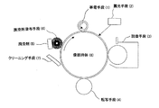
従来の画像形成装置は、図1に示したように、帯電手段(1)により像担持体(8)表面の画像形成領域を均一に帯電させ、露光手段(2)により像担持体(1)に書き込みを行い、現像手段(3)により像担持体8上に摩擦帯電させたトナーにより画像を形成する。続いて、転写手段(4)により給紙手段(9)から搬送される印刷用紙に直接または中間転写体を介して間接的に印刷用紙に、像担持体(8)上のトナー画像を転写し、その後、定着手段(10)により画像を印刷用紙に定着させる。一方、像担持体8上に転写しきれずに残留した転写残トナーは、クリーニング手段(7)により像担持体(8)上から掻き落とされる。像担持体(8)は円筒形状、または、ベルト形状に形成されており、これら一連の画像形成プロセスを経た後、そのまま次画像形成プロセスに入る。 In the conventional image forming apparatus, as shown in FIG. 1, the image forming area on the surface of the image carrier (8) is uniformly charged by the charging means (1), and the image carrier (1) is exposed by the exposure means (2). Then, an image is formed by toner triboelectrically charged on the image carrier 8 by the developing means (3). Subsequently, the toner image on the image carrier (8) is transferred directly to the printing paper conveyed from the paper feeding means (9) by the transfer means (4) or indirectly to the printing paper through the intermediate transfer member. Thereafter, the image is fixed on the printing paper by the fixing means (10). On the other hand, the untransferred toner remaining on the image carrier 8 without being transferred is scraped off from the image carrier (8) by the cleaning means (7). The image carrier (8) is formed in a cylindrical shape or a belt shape, and after going through a series of these image forming processes, it enters the next image forming process as it is.
このようなプロセスからなる画像形成装置は、像担持体を一つのみ持ち、その像担持体で各色について画像を形成するリボルバ方式、また、像担持体を各色1本で使用するタンデム方式があり、リボルバ方式ではコストが安く、また、タンデム方式ではコストが高くなってしまうが、高速印刷を行うことができる。現在の主流は、高速印刷が可能なタンデム方式である。 An image forming apparatus comprising such a process has a revolver system that has only one image carrier and forms an image for each color with the image carrier, and a tandem system that uses one image carrier for each color. In the revolver method, the cost is low, and in the tandem method, the cost is high, but high-speed printing can be performed. The current mainstream is the tandem method that enables high-speed printing.
ここで、帯電手段(1)、露光手段(2)、現像手段(3)、転写手段(4)、クリーニング手段(7)等、及び、これら手段に用いられるトナー、潤滑剤、潤滑剤塗布手段等について説明すれば以下のとおりである。 Here, the charging means (1), the exposure means (2), the developing means (3), the transfer means (4), the cleaning means (7), etc., and the toner, lubricant and lubricant application means used in these means The following is a description of the above.
(帯電手段)
帯電手段(1)としては、DC、または、DCにACを重畳した、近接帯電方式、接触帯電方式、また、コロナ帯電方式が挙げられる。コロナ帯電方式としては、コロトロン帯電器、スコロトロン帯電器などがある。
従来では、像担持体に帯電を施す帯電手段としては、コロナ放電を利用したコロトロン帯電器、また、スコロトロン帯電器などが主流であった。しかしながら、このコロナ放電を用いた帯電手段は、オゾンが多量に発生してしまったり、また、コロナ放電によって生成されたNOxなどが像担持体に付着し、経時で像流れといった不具合を起こすという問題点があった。またコロナ放電を行わせるために5〜10kVという高電圧を印加する高電圧電源が必要であるので画像形成装置の低コスト化を図ることが難しかった。
そこで近年、画像形成装置に採用することができる帯電手段として、コロナ放電を利用しない、帯電手段を像担持体に接触させる接触型の帯電手段や、帯電手段を像担持体に近接させる近接型の帯電手段が多く提案されている。この接触型・近接型の帯電手段では、上記コロナ放電を用いた帯電手段の場合に挙げた問題点の多くが解消される一方、像担持体の摩耗量が増大し、寿命を短くしてしまうという問題も発生している。また、印加電圧に交流を用いた場合は騒音の発生も問題になっている。加えて、前記帯電手段がトナーや紙紛を像担持体に擦りつけるので、像担持体表面の汚染を助長し、また、帯電手段表面の汚れによる問題も発生している。そこで、直流電圧に交流電圧を重畳した電圧を帯電部材に印加して感光体を帯電させるAC電圧重畳の帯電方式が注目されている。
(Charging means)
Examples of the charging means (1) include DC, a proximity charging system in which AC is superimposed on DC, a contact charging system, and a corona charging system. Examples of the corona charging method include a corotron charger and a scorotron charger.
Conventionally, corotron chargers utilizing corona discharge, scorotron chargers and the like have been mainstream as charging means for charging an image carrier. However, the charging means using the corona discharge has a problem that a large amount of ozone is generated or NOx generated by the corona discharge adheres to the image carrier and causes a problem such as image flow over time. There was a point. In addition, since a high voltage power source that applies a high voltage of 5 to 10 kV is required to perform corona discharge, it is difficult to reduce the cost of the image forming apparatus.
Therefore, in recent years, as a charging unit that can be employed in an image forming apparatus, a contact type charging unit that does not use corona discharge, a charging unit that contacts the image carrier, or a proximity type that closes the charging unit to the image carrier. Many charging means have been proposed. In this contact type / proximity type charging means, many of the problems mentioned in the case of the charging means using the corona discharge are solved, but the wear amount of the image carrier increases and the life is shortened. There is also a problem. In addition, when alternating current is used as the applied voltage, noise is also a problem. In addition, since the charging unit rubs toner or paper dust against the image carrier, the surface of the image carrier is promoted to be contaminated, and a problem due to contamination of the surface of the charging unit has also occurred. Therefore, an AC voltage superposition charging method in which a voltage obtained by superimposing an alternating current voltage on a direct current voltage is applied to a charging member to charge the photosensitive member is attracting attention.
(露光手段)
露光手段(2)としては、LD、LEDランプ、キセノンランプによる露光方法が挙げられる。
(Exposure means)
Examples of the exposure means (2) include an exposure method using an LD, an LED lamp, and a xenon lamp.
(現像手段)
現像手段としては、一成分現像手段や、トナーとキャリアを混合して現像に用いる二成分現像手段による現像方法が挙げられる。
現像剤としては、トナー及びキャリアからなる2成分現像剤と、磁性あるいは非磁性トナーのみの1成分現像剤とがある。これらのトナーの製造は樹脂、顔料、帯電制御剤、離型剤を溶融混練し、冷却した後に粉砕、分級する混練粉砕法が一般的であるが、粒径、形状が揃わず、これらを制御するのは困難である。
このような状況下で、近年トナー粒子の粒径を意図的に制御し、前述の問題を解消しようとする試みがあり、水系での造粒として乳化重合法や溶解懸濁法といった重合トナー工法が盛んになった。
また近年、高画質化への要求が高まり、特にカラー画像形成において高精細な画像を実現するため、トナーの小径化かつ粒径均一化の要求も高まっている。粒径分布の広いトナーを用いて画像形成を行うと、微粉トナーが現像スリーブ、接触・近接帯電手段、クリーニングブレード、像担持体(感光体)、キャリアなどを汚染したり、トナー飛散したりするという問題が大きくなり、高画質および高信頼性を同時に果たすことが困難であった。
一方、粒径が揃い、粒径分布がシャープになると個々のトナー粒子の現像挙動が揃って、微小ドット再現性が大きく向上する。しかしながら、小粒径かつ粒子径の揃ったトナーはクリーニング性に関して、問題が生じる。特に、ブレードクリーニングでは均一かつ小粒径なトナーを安定的にクリーニングすることは不可能である。そこで、トナーの工夫により、クリーニング性を改善する方法が様々な形で提案されている。その中の一つとして、トナーを球形から異形させ、対応する方法がある。トナー形状を異形化することで、トナーの粉体流動性を低下させ、ブレードクリーニングによって堰き止めやすくするものである。ただし、トナーの異形度合いを大きくしすぎると、現像の際などにトナーの挙動が不安定となり、微小ドット再現性が悪化することになる。このように、トナーの転写品質、転写効率、クリーニング性などの特性はトナー形状に影響されることから、前記特性を備えたトナーを得るためには、トナー形状分布の最適設計が要求される。
(Development means)
Examples of the developing means include a one-component developing means and a developing method using a two-component developing means for mixing and developing toner and a carrier.
As the developer, there are a two-component developer composed of a toner and a carrier and a one-component developer composed of only a magnetic or non-magnetic toner. The production of these toners is generally a kneading and pulverization method in which a resin, pigment, charge control agent, and release agent are melt-kneaded, cooled and then pulverized and classified, but the particle size and shape are not uniform, and these are controlled. It is difficult to do.
Under such circumstances, recently, there has been an attempt to control the particle size of toner particles intentionally to solve the above-mentioned problems, and polymerized toner methods such as emulsion polymerization method and dissolution suspension method as aqueous granulation. Became popular.
In recent years, there has been an increasing demand for higher image quality, and in particular, in order to realize high-definition images in color image formation, there has also been an increasing demand for toner diameter reduction and particle size uniformity. When an image is formed using toner having a wide particle size distribution, the fine powder toner contaminates the developing sleeve, the contact / proximity charging means, the cleaning blade, the image carrier (photoconductor), the carrier, etc., or the toner scatters. It has become difficult to achieve high image quality and high reliability at the same time.
On the other hand, when the particle size is uniform and the particle size distribution is sharp, the development behavior of the individual toner particles is uniform, and the reproducibility of minute dots is greatly improved. However, a toner having a small particle size and a uniform particle size has a problem with respect to cleaning properties. In particular, it is impossible to stably clean a toner having a uniform and small particle diameter by blade cleaning. In view of this, various methods have been proposed for improving the cleaning property by devising the toner. One of them is a method in which the toner is deformed from a spherical shape to cope with it. By changing the shape of the toner, the powder fluidity of the toner is lowered and it is easy to dam by blade cleaning. However, if the degree of toner deformation is excessively large, the behavior of the toner becomes unstable during development and the like, and the fine dot reproducibility deteriorates. As described above, characteristics such as toner transfer quality, transfer efficiency, and cleaning performance are affected by the toner shape. Therefore, in order to obtain a toner having the above characteristics, an optimum design of the toner shape distribution is required.
(転写手段)
転写手段(4)としては、転写ベルト、転写チャージャ、転写ローラによる転写方法が挙げられる。
(Transfer means)
Examples of the transfer means (4) include a transfer method using a transfer belt, a transfer charger, and a transfer roller.
(クリーニング手段)
クリーニング手段(7)としては、ポリウレタンゴム、シリコーンゴム、ニトリルゴム、クロロプレンゴム等から成る、ブレード形状のクリーニングブレード、または、ファーブラシ、弾性ローラ、チューブ被覆ローラ、不織布などが挙げられる。
従来においては、電子写真方式における画像形成装置のクリーニング方法は、ブレードによるクリーニング方式が主であり、ブレードのみのクリーニング手段を有する画像形成装置が多数存在した。また、高速機においては、部分的に多量のトナーが付着した状態を避けるため、クリーニング補助手段を設けたものも存在する。このとき、クリーニング手段としてクリーニングブレードを用いた場合には、像担持体に対してトレーリング、またはカウンタで当接するようになっている。
クリーニング手段のみでは、像担持体上のトナーのクリーニングが不十分な場合、像担持体回転方向下流側でクリーニング手段の上流側に、クリーニング補助手段を搭載し、クリーニング性を向上させる手段がとられてきた。クリーニング補助手段としては、ファーブラシ、弾性ローラ、チューブ被覆ローラ、不織布などが挙げられる。
従来のクリーニング補助手段はクリーニング手段の上流側に設置され、上記のものが使用されてきた。これは、クリーニング手段に入力されるトナーを機械的にかき乱し、クリーニング手段でのクリーニング性を向上することを狙いとしている。この時クリーニング補助手段に電圧を印加し、トナーの極性を制御してクリーニング性を向上させている画像形成装置も発売されている。
(Cleaning means)
Examples of the cleaning means (7) include a blade-shaped cleaning blade made of polyurethane rubber, silicone rubber, nitrile rubber, chloroprene rubber, or the like, or a fur brush, an elastic roller, a tube-covered roller, and a nonwoven fabric.
Conventionally, the cleaning method of an image forming apparatus in the electrophotographic method is mainly a cleaning method using a blade, and there are a large number of image forming apparatuses having cleaning means only for the blade. Some high-speed machines are provided with cleaning assisting means in order to avoid a state in which a large amount of toner is partially attached. At this time, when a cleaning blade is used as the cleaning means, the image carrier is brought into contact with a trailing or counter.
If the cleaning of the toner on the image carrier is insufficient with only the cleaning means, a means for improving the cleaning property is provided by installing a cleaning auxiliary means on the downstream side in the rotation direction of the image carrier and upstream of the cleaning means. I came. Examples of the cleaning auxiliary means include a fur brush, an elastic roller, a tube covering roller, and a nonwoven fabric.
The conventional cleaning auxiliary means is installed on the upstream side of the cleaning means, and the above-described one has been used. This is intended to mechanically disturb the toner input to the cleaning means and improve the cleaning performance of the cleaning means. At this time, an image forming apparatus in which a voltage is applied to the cleaning auxiliary means and the polarity of the toner is controlled to improve the cleaning property has been put on the market.
また、上記のような画像形成装置において、水系造粒トナーには、より高画質な画像を得るためにその使用が望まれているが、クリーニング性の確保が困難である。そのため、球形度の高いトナーを用いる場合では、クリーニング性の余裕度向上、また、帯電手段における放電による像担持体磨耗、クリーニング手段やトナーなどの接触による、像担持体磨耗、像担持体フィルミング防止のために、像担持体に潤滑剤を塗布する手段をもたせた構成をとることも多い。 Further, in the image forming apparatus as described above, the water-based granulated toner is desired to be used for obtaining a higher quality image, but it is difficult to ensure the cleaning property. Therefore, in the case of using a toner having a high sphericity, the margin of cleaning performance is improved, the image carrier wear due to discharge in the charging means, the image carrier wear due to the contact of the cleaning means or toner, and the image carrier filming. In order to prevent this, the image carrier is often provided with a means for applying a lubricant.
(水系造粒トナー)
水系造粒トナーの製造について、特許文献1等には懸濁重合法や乳化重合法などによって湿式中で球形トナーを製造する技術が、また特許文献2、特許文献3等には粉砕トナーを熱処理することによって球形化する技術が提案されており、このようなトナー製造方法によると、トナーの小粒径化も容易である。
(Water-based granulated toner)
Regarding the production of water-based granulated toner, Patent Document 1 and the like describe a technique for producing a spherical toner in a wet manner by a suspension polymerization method or an emulsion polymerization method, and Patent Document 2 and Patent Document 3 and the like treat a pulverized toner by heat treatment. Thus, a technique for making the particles spherical has been proposed, and according to such a toner manufacturing method, it is easy to reduce the particle size of the toner.
(潤滑剤塗布手段)
像担持体の高寿命化、高画質化の為に、像担持体上に潤滑剤を塗布することが行われている。潤滑剤を塗布する目的としては、次の課題がある。(i)トナーフィルミング(融着)の発生を防止する。(ii)低摩擦係数化によって、転写効率の向上、及び、クリーニング不良の防止があげられる。これらの課題に対しては、例えば特許文献4、特許文献5、特許文献6、特許文献7などに記載される技術が知られており、潤滑剤(5)を像担持体(8)上に塗布することによって解決している。これらの例では、いずれの場合も像担持体(8)上に潤滑剤(5)を塗布し、低摩擦係数化することによって課題を解決している。
(Lubricant application means)
In order to increase the life and image quality of an image carrier, a lubricant is applied on the image carrier. The purpose of applying the lubricant is as follows. (I) The occurrence of toner filming (fusion) is prevented. (Ii) By reducing the friction coefficient, the transfer efficiency can be improved and the cleaning failure can be prevented. For these problems, for example, techniques described in
潤滑剤塗布手段としては、ファーブラシやループブラシ、ローラ、ベルトにより像担持体に塗布する方法、または、固形潤滑剤や潤滑材の粉体を直接像担持体に塗布する方法でもよい。
潤滑剤を像担持体に塗布する他の方法としては、潤滑剤をトナーに外添し、トナー供給とともに潤滑剤を像担持体に塗布する技術も知られているが、この方法では、トナーが供給されない領域(非画像領域)においては、潤滑剤は像担持体に塗布されることがなく、放電による像担持体磨耗、接触部材による像担持体磨耗を防ぐことができなかった。
また、クリーニング補助手段に固形潤滑剤を直接接触させ、潤滑剤を像担持体に塗布する方法も知られているが、この方法では、転写残トナーがある領域(画像領域)では、潤滑剤は像担持体に塗布されることがなく、放電による像担持体磨耗、接触部材による像担持体磨耗を防ぐことが出来なかった。
The lubricant applying means may be a method of applying to the image carrier using a fur brush, loop brush, roller, or belt, or a method of applying solid lubricant or lubricant powder directly to the image carrier.
As another method for applying the lubricant to the image carrier, a technique in which the lubricant is externally added to the toner and the lubricant is applied to the image carrier together with the toner supply is also known. In the non-supplied region (non-image region), the lubricant was not applied to the image carrier, and the image carrier wear due to discharge and the image carrier wear due to the contact member could not be prevented.
Also known is a method in which a solid lubricant is brought into direct contact with the cleaning auxiliary means, and the lubricant is applied to the image carrier. In this method, in the region where there is residual transfer toner (image region), the lubricant is It was not applied to the image carrier, and it was impossible to prevent image carrier wear due to discharge and image carrier wear due to the contact member.
これらの問題を解決するため、像担持体回転方向クリーニング手段下流側において潤滑剤の粉体を直接像担持体に接触させ、さらに像担持体回転方向下流側かつ帯電手段上流側に潤滑剤ならしブレードを設けて、像担持体全表面に潤滑剤を塗布する方法も考案された。また、同様の潤滑剤塗布均一化を測れる手段としては、像担持体回転方向でかつクリーニング手段下流側において潤滑剤塗布手段に潤滑剤を押当て、潤滑剤塗布手段により潤滑剤を像担持体に塗布し、さらに像担持体回転方向下流側かつ帯電手段上流側に潤滑剤ならしブレードを設けて、像担持体全表面に潤滑剤を塗布する方法も考案された。これらの方法により、潤滑剤を像担持体全表面に塗布し、帯電手段での放電による像担持体磨耗、また、接触部材による像担持体磨耗から像担持体全表面を保護できるようになった。 In order to solve these problems, the lubricant powder is brought into direct contact with the image carrier downstream of the image carrier rotation direction cleaning means, and the lubricant is further distributed downstream of the image carrier rotation direction and upstream of the charging means. A method of applying a lubricant to the entire surface of the image carrier by providing a blade has also been devised. Further, as means for measuring the same uniform application of the lubricant, the lubricant is pressed against the lubricant application means in the rotation direction of the image carrier and downstream of the cleaning means, and the lubricant is applied to the image carrier by the lubricant application means. There has also been devised a method of applying a lubricant to the entire surface of the image carrier by applying the lubricant and providing a lubricant leveling blade on the downstream side in the rotation direction of the image carrier and upstream of the charging means. By these methods, the lubricant can be applied to the entire surface of the image carrier, and the entire surface of the image carrier can be protected from the wear of the image carrier due to the discharge by the charging means and the wear of the image carrier by the contact member. .
また、帯電手段と像担時体の長寿命化をはかる為に、非接触の帯電手段を用い、像担持体の感光層に無機微粒子を分散させ、ステアリン酸亜鉛などを潤滑剤として塗布することによって耐磨耗性を向上させている例として、特許文献8に記載の技術がある。加えて、像担持体の表面に塗布された潤滑剤を、帯電手段と現像手段間で薄く均一に付着、且つ、大きい径の潤滑材をせき止める為のブレード状の補助部材を持った画像形成装置の例として、特許文献9に記載のものが知られている。
一方、一般的に、接触帯電方式及び近接帯電方式は、コロナ帯電方式と比較して、放電生成物の量が少なく、低電力で帯電を行うことができる。しかしながら、これら帯電方式は、感光体と帯電部材とが接触し、又は、感光体と帯電部材との距離が感光体とチャージワイヤとの距離よりも短くなるため、感光体に対するハザードは、コロナ帯電方式よりも大きいことが明らかになっている。特に、交流電圧を重畳した場合、放電が交流電圧の周波数に応じて繰り返されるためにハザードは大きくなり、その結果、感光体表面の化学的劣化が進行し、やがては、感光体表面に膜削れが発生する。感光体表面に潤滑剤が塗布されていた場合には、その潤滑剤の分子構造や表面エネルギー等が変化して潤滑性が失われ、潤滑剤は徐々に削られて最終的には消失する、等の問題も有している。
In order to extend the life of the charging means and the image carrier, non-contact charging means is used, inorganic fine particles are dispersed in the photosensitive layer of the image carrier, and zinc stearate or the like is applied as a lubricant. As an example in which the wear resistance is improved, there is a technique described in Patent Document 8. In addition, an image forming apparatus having a blade-like auxiliary member for adhering the lubricant applied to the surface of the image carrier thinly and uniformly between the charging means and the developing means, and clogging the lubricant having a large diameter As an example of this, the one described in Patent Document 9 is known.
On the other hand, in general, the contact charging method and the proximity charging method have a smaller amount of discharge products than the corona charging method, and can be charged with low power. However, in these charging methods, the photosensitive member and the charging member are in contact with each other, or the distance between the photosensitive member and the charging member is shorter than the distance between the photosensitive member and the charge wire. It is clear that it is larger than the method. In particular, when an AC voltage is superimposed, the hazard increases because the discharge is repeated according to the frequency of the AC voltage. As a result, chemical deterioration of the surface of the photoconductor progresses, and eventually the film is scraped on the surface of the photoconductor. Will occur. When lubricant is applied to the surface of the photoreceptor, the molecular structure or surface energy of the lubricant is changed and the lubricity is lost. The lubricant is gradually scraped and eventually disappears. Etc. also have problems.
(潤滑剤塗布量)
これら従来技術に鑑み、接触帯電方式又は近接帯電方式を採用する画像形成装置において、感光体表面に塗布する潤滑剤の量を、感光体表面の劣化を抑制できる量として、像担持体への潤滑剤(以降、潤滑物質ともいう)の塗布量として、特許文献10には、以下のように最適な塗布量が提示されている。
即ち、X線光電子分光分析装置(XPS)により検出される該被帯電体最表面を構成する物質の全元素の元素個数総和に対する、該XPSにより検出される該潤滑物質の特定元素の元素個数割合A[%]を、次の[数1]式以上とする。
[数1]
1.52×10⁻⁴×{Vpp−2×Vth}×f/v×Nα
(ここで、VppはAC電圧のピークツーピーク電圧値[単位:V]、fは帯電手段1に印加する交流成分の周波数[単位:Hz]、vは被帯電体表面の移動速度[単位:mm/sec]、Nαは潤滑物質を構成する元素のうち特定元素の1分子中における元素個数である。また、Vthは放電開始電圧であり、以下の[数2]式により求められる。)
[数2]
Vth=312+6.2×(d/εopc+Gp/εair)+√(7737.6×d/εopc)
(このとき、dは被帯電体の膜厚[単位:μm]、εopcは被帯電体の比誘電率、εairは被帯電体と帯電手段(1)の間の空間における比誘電率、Gpは帯電手段(1)表面と被帯電体表面との最近接距離[単位:μm]である。)
また、上記XPSにより検出される該被帯電体最表面を構成する物質の全元素の元素個数総和に対する、該XPSにより検出される該潤滑物質を構成する元素個数割合A[%]を、次の[数3]式以上とする。
[数3]
1.52×10⁻⁴×{Vpp−2×Vth}×f/v×Nβ
(ここで、Nβ:潤滑物質1分子を構成する元素個数総和から水素元素の元素個数を引いた値。)
(Amount of lubricant applied)
In view of these conventional techniques, in an image forming apparatus employing a contact charging method or a proximity charging method, the amount of lubricant applied to the surface of the photoconductor is set to an amount capable of suppressing deterioration of the surface of the photoconductor, and the image carrier is lubricated. As an application amount of the agent (hereinafter also referred to as a lubricating substance), Patent Document 10 proposes an optimal application amount as follows.
That is, the ratio of the number of elements of the specific element of the lubricating material detected by the XPS to the total number of elements of all elements of the material constituting the outermost surface of the charged body detected by an X-ray photoelectron spectrometer (XPS) Let A [%] be equal to or greater than the following [Equation 1].
[Equation 1]
1.52 × 10 −4 × {Vpp−2 × Vth} × f / v × Nα
(Where Vpp is the peak-to-peak voltage value [unit: V] of the AC voltage, f is the frequency of the AC component applied to the charging means 1 [unit: Hz], and v is the moving speed of the surface of the object to be charged [unit: V]. mm / sec], Nα is the number of elements in one molecule of a specific element among the elements constituting the lubricant, and Vth is the discharge start voltage, which is obtained by the following [Equation 2].
[Equation 2]
Vth = 312 + 6.2 × (d / εopc + Gp / εair) + √ (7737.6 × d / εopc)
(At this time, d is the film thickness [unit: μm] of the member to be charged, εopc is the relative dielectric constant of the member to be charged, εair is the relative dielectric constant in the space between the member to be charged and the charging means (1), and Gp is Charging means (1) The closest distance [unit: μm] between the surface and the surface of the object to be charged.)
Further, the ratio A [%] of the number of elements constituting the lubricating material detected by the XPS with respect to the total number of elements of all the elements constituting the material to be charged detected by the XPS is expressed as follows: [Equation 3] It is set to the formula or more.
[Equation 3]
1.52 × 10 −4 × {Vpp−2 × Vth} × f / v × Nβ
(Here, Nβ: a value obtained by subtracting the number of hydrogen elements from the total number of elements constituting one molecule of the lubricating substance.)
上記の潤滑剤塗布量に関する発明により、潤滑剤を像担持体全表面に均一に塗布し、帯電手段での放電による像担持体磨耗を低減し、像担持体寿命を延ばすことができた。しかしながら、本発明者らの検討により、高画質を長期にわたり出力するには、上記潤滑剤塗布技術を用いた従来技術でも不十分なことが判明した。具体的には、上記潤滑剤塗布技術を用いることにより、帯電手段による放電による像担持体磨耗は防ぐことが出来たが、クリーニング手段にクリーニングブレードを用いた場合、そのエッジが早期に磨耗し、像担持体表面のクリーニング不良による画像品質劣化が発生する。また一方で、クリーニング不良とはことなる異常画像、具体的には像流れが発生する。その理由は、次の理由によるものと考えられる。 According to the invention relating to the amount of applied lubricant, the lubricant can be uniformly applied to the entire surface of the image carrier, and the wear of the image carrier due to discharge by the charging means can be reduced, and the life of the image carrier can be extended. However, as a result of studies by the present inventors, it has been found that the conventional technique using the lubricant application technique is insufficient to output high image quality over a long period of time. Specifically, by using the lubricant application technique, it was possible to prevent image carrier wear due to discharge by the charging means, but when a cleaning blade was used as the cleaning means, the edge was worn early, Image quality deterioration occurs due to poor cleaning of the image carrier surface. On the other hand, an abnormal image that is different from a cleaning failure, specifically, an image flow occurs. The reason is considered to be as follows.
これまでの検討により、当初像担持体表面の摩擦係数を低減させることを狙って像担持体に潤滑剤を塗布していたが、帯電手段が近接または直接放電を用いた帯電手段を用いた場合、像担持体表面に塗布された潤滑剤が分解され、分子鎖がどんどん短くなり、潤滑剤が劣化することによって、像担持体表面の摩擦係数が、潤滑剤を塗布しない場合よりも実は大きくなっていることが判明した。さらにこの場合、像担持体表面状態は均一ではなく、像担持体表面の摩擦係数分布が大きくなる。
つまり、近接または接触帯電方式を用いた画像形成装置では、潤滑剤を塗布することによって、像担持体表面の摩擦係数が平均的に大きくなり、さらに、その分布も大きくなる。そのため、クリーニング手段にクリーニングブレードを用いた場合、通常潤滑剤を塗布しない場合よりも、クリーニングブレードエッジの巻き込み量は大きくなり、劣化が促進される。
さらに像担持体表面の摩擦係数の分布が大きくなることにより、クリーニングブレードエッジのスティックスリップが大きくなり、さらに磨耗が促進される。
このため、上記のような、クリーニングブレードエッジ磨耗による画像不良が発生すると考えられる。また像流れの発生については、像担持体表面にある潤滑剤は、放電を受けて劣化することにより、その表面性(濡れ性)が大きくなる。そのため、像担持体表面に水分が吸着しやすくなり、像担持体表面の抵抗が低下、潜像書き込み後の電荷移動が発生し、像流れ現象が起きると考えられる。
以上の理由により、クリーニングブレードエッジ磨耗を低減し、像担持体磨耗も低減し、また、像流れ以上画像を発生することなく長期にわたり高画質を得るためには、常に劣化した潤滑剤を除去し続けることが必要となる。
According to previous studies, lubricant was applied to the image carrier with the aim of reducing the friction coefficient on the surface of the image carrier, but the charging means used a charging means that uses proximity or direct discharge. The lubricant applied to the surface of the image carrier is decomposed, the molecular chain becomes shorter and the lubricant deteriorates, so that the coefficient of friction on the surface of the image carrier is actually larger than when no lubricant is applied. Turned out to be. Further, in this case, the surface state of the image carrier is not uniform, and the friction coefficient distribution on the surface of the image carrier becomes large.
That is, in the image forming apparatus using the proximity or contact charging method, by applying the lubricant, the coefficient of friction on the surface of the image carrier increases on average, and the distribution also increases. For this reason, when the cleaning blade is used as the cleaning means, the amount of the cleaning blade edge involved becomes larger than that when the lubricant is not normally applied, and the deterioration is promoted.
Further, the distribution of the coefficient of friction on the surface of the image carrier is increased, so that the stick slip of the cleaning blade edge is increased and the wear is further promoted.
For this reason, it is thought that the image defect by the cleaning blade edge wear as described above occurs. Regarding the occurrence of image flow, the lubricant on the surface of the image carrier is deteriorated by receiving electric discharge, so that the surface property (wetting property) is increased. For this reason, it is considered that the moisture tends to be adsorbed on the surface of the image carrier, the resistance of the surface of the image carrier is lowered, the charge transfer after the latent image is written, and the image flow phenomenon occurs.
For these reasons, cleaning blade edge wear is reduced, image carrier wear is also reduced, and in order to obtain high image quality over a long period of time without generating more images than the image flow, always remove the deteriorated lubricant. It is necessary to continue.
本発明は、上記の従来技術が有する問題点に鑑みてなされたものであって、その目的は、画像形成が行なわれる間に上記の劣化した潤滑剤が除去され、その結果、像担持体上には劣化した潤滑剤の存在がなく、常に安定した高品質画像が得られる画像形成装置を提供することである。本発明の他の目的は、像担持体を長期にわたって安定して使用することができる画像形成装置を提供することである。 The present invention has been made in view of the above-described problems of the prior art, and an object thereof is to remove the above-described deteriorated lubricant during image formation, and as a result, on the image carrier. An object of the present invention is to provide an image forming apparatus in which no deteriorated lubricant is present and a stable high quality image can be obtained at all times. Another object of the present invention is to provide an image forming apparatus capable of stably using an image carrier for a long period of time.
本発明者らは、上記目的を達成するために多くの研究・検討を行ってきた結果、特定のトナーを用いることによって画像形成が行なわれる間に上記の劣化した潤滑剤が除去されることを見出した。即ち、本発明は、特定のトナーを用いることで、トナー表面に潤滑剤を吸着する面積を増加させ、そのトナーによって劣化した潤滑剤を像担持体表面から除去し、クリーニングブレード磨耗、像流れ画像の発生を防ぐことができるようにものである。
したがって、像担持体表面に必要な潤滑剤を塗布した上で、劣化した潤滑剤を除去するため、トナーのBET比表面積を大きく必要があるが、本発明におけるトナーは水系で造粒されたトナーであっても、少なくとも結着樹脂と、着色剤と、層間のイオンの少なくとも一部を有機物イオンで変性した変性層状無機鉱物をトナー中に含有させることにより、トナーとしてもBET比表面積を大きくすることができる。
またさらに、無機微粒子をトナー母体に外添し、BET比表面積が2.5〜7.0(m2/g)となるようにトナーを製造することで、他システムにおける不具合のない範囲でトナーに必要な機能を付与しつつ、潤滑剤除去機能も併せ持たせることができる。
As a result of many studies and studies to achieve the above object, the present inventors have found that the above-described deteriorated lubricant is removed during image formation by using a specific toner. I found it. That is, according to the present invention, by using a specific toner, the area for adsorbing the lubricant on the toner surface is increased, the lubricant deteriorated by the toner is removed from the surface of the image carrier, and the cleaning blade is worn and the image flow image is removed. It is intended to prevent the occurrence of.
Therefore, it is necessary to increase the BET specific surface area of the toner in order to remove the deteriorated lubricant after applying the necessary lubricant on the surface of the image carrier. However, the toner in the present invention is a toner granulated in water system. Even so, the BET specific surface area of the toner can be increased by including in the toner at least a binder resin, a colorant, and a modified layered inorganic mineral in which at least some of the ions between layers are modified with organic ions. be able to.
Further, by adding inorganic fine particles to the toner base and producing the toner so that the BET specific surface area is 2.5 to 7.0 (m 2 / g), the toner can be used within a range where there is no problem in other systems. In addition, a lubricant removing function can be provided while providing a necessary function.
即ち、上記の課題は下記(1)〜(11)の発明によって解決される。
(1)像担持体と、近接または直接放電により像担持体表面を帯電させる帯電手段と、像担持体上に露光することによって潜像を書き込む露光手段と、像担持体上に書き込まれた潜像をトナーで現像させる現像手段と、現像されたトナーを中間転写体または印刷用紙に転写する転写手段とを有する画像形成装置において、
前記像担持体への潤滑剤塗布量が、下記の数式1〜3に示される範囲にあり、
X線光電子分光分析装置(XPS)により検出される前記像担持体最表面を構成する物質の全元素の元素個数総和に対する、前記XPSにより検出される前記潤滑物質の特定元素の元素個数割合A(%)は、下記数1を満たし、
[数1]
A ≧ 1.52×10⁻⁴×{Vpp−2×Vth}×f/v×Nα
(ここで、VppはAC電圧のピークツーピーク電圧値[単位:V]、
fは帯電手段1に印加する交流成分の周波数[単位:Hz]、
vは被帯電体表面の移動速度[単位:mm/sec]、
Nαは潤滑物質を構成する元素のうち特定元素の1分子中における元素個数である。
また、Vthは放電開始電圧であり、以下の数2の式により求められる。)
[数2]
Vth=312+6.2×(d/εopc+Gp/εair)+√(7737.6×d/εopc)
(このとき、dは被帯電体の膜厚[単位:μm]、
εopcは被帯電体の比誘電率、
εairは被帯電体と帯電手段(1)の間の空間における比誘電率、
Gpは帯電手段(1)表面と被帯電体表面との最近接距離[単位:μm]である。)
また、前記XPSにより検出される前記像担持体最表面を構成する物質の全元素の元素個数総和に対する、前記XPSにより検出される前記潤滑物質を構成する元素個数割合B(%)は、下記数3を満たし、
[数3]
B ≧ 1.52×10⁻⁴×{Vpp−2×Vth}×f/v×Nβ
(ここで、Nβ:潤滑物質1分子を構成する元素個数総和から水素元素の元素個数を引いた値。)
(前記潤滑物質は脂肪酸金属塩であって前記特定元素が金属であり、かつ前記Nαが1、前記Nβが41である。前記帯電手段と前記像担持体との最近接距離を1〜100[μm]とする。)
前記現像手段で像担持体の現像に使用されるトナーは、水系で造粒されたトナーであって、少なくとも結着樹脂と、着色剤と、層間のイオンの少なくとも一部を有機物イオンで変性した変性層状無機鉱物とを含有し、かつ、BET比表面積が2.5〜7.0(m2/g)のトナーである、
ことを特徴とすることを特徴とする画像形成装置。
(2)前記変性層状無機鉱物は、金属カチオンの少なくとも一部を有機カチオンで変性したものであることを特徴とする前記(1)に記載の画像形成装置。
(3)前記トナーは、体積平均粒径(Dv)と個数平均粒径(Dn)との比(Dv/Dn)が1.00〜1.40の範囲にあることを特徴とする前記(1)又は(2)に記載の画像形成装置。
(4)前記トナーは、2μm以下の粒子が1〜10個数%であることを特徴とする前記(1)又は(2)に記載の画像形成装置。
(5)前記トナーは、複数の無機微粒子を外添して作成されることを特徴とすることを特徴とする前記(1)又は(2)に記載の画像形成装置。
(6)前記無機微粒子は、少なくともシリカとチタンを含むことを特徴とする前記(5)に記載の画像形成装置。
(7)前記像担持体の回転方向にクリーニング手段、及び下流側に潤滑剤塗布手段を設けたことを特徴とする前記(1)又は(2)に記載の画像形成装置。
(8)前記像担持体の回転方向にクリーニング手段、及び下流側に潤滑剤塗布手段を設け、さらに前記潤滑剤塗布手段の下流側かつ帯電手段上流側に潤滑剤ならし手段を設けたことを特徴とする前記(1)又は(2)に記載の画像形成装置。
(9)前記像担持体が、フィラーを分散させた感光体であることを特徴とする前記(1)〜(8)のいずれかに記載の画像形成装置。
(10)前記像担持体が、充填材で補強された表面層を有する有機感光体、架橋型電荷輸送材料を使用した有機感光体、又は充填材で補強された表面層を有しかつ架橋型電荷輸送材料を使用した有機感光体であることを特徴とする前記(1)〜(8)のいずれかに記載の画像形成装置。
(11)前記像担持体が、アモルファスシリコン感光体であることを特徴とする前記(1)〜(8)のいずれかに記載の画像形成装置。
That is, said subject is solved by invention of following (1)-(11).
(1) an image carrier, a charging unit for charging the surface of the image carrier by proximity or direct discharge, an exposure unit for writing a latent image by exposing the image carrier, and a latent image written on the image carrier. In an image forming apparatus comprising: a developing unit that develops an image with toner; and a transfer unit that transfers the developed toner to an intermediate transfer member or printing paper.
The amount of lubricant applied to the image carrier is in the range represented by the following formulas 1 to 3,
Ratio of the number of elements A of the specific element of the lubricant detected by the XPS to the total number of elements of the elements constituting the outermost surface of the image carrier detected by the X-ray photoelectron spectrometer (XPS) A ( %) Satisfies the following number 1,
[Equation 1]
A ≧ 1.52 × 10 −4 × {Vpp−2 × Vth} × f / v × Nα
(Where Vpp is the AC voltage peak-to-peak voltage value [unit: V],
f is the frequency [unit: Hz] of the AC component applied to the charging means 1;
v is the moving speed of the surface of the member to be charged [unit: mm / sec],
Nα is the number of elements in one molecule of a specific element among the elements constituting the lubricating material.
Vth is a discharge start voltage, and is obtained by the following equation (2). )
[Equation 2]
Vth = 312 + 6.2 × (d / εopc + Gp / εair) + √ (7737.6 × d / εopc)
(At this time, d is the film thickness of the member to be charged [unit: μm],
εopc is the dielectric constant of the object to be charged,
εair is the relative dielectric constant in the space between the object to be charged and the charging means (1),
Gp is the closest distance [unit: μm] between the surface of the charging means (1) and the surface of the member to be charged. )
The ratio B (%) of the number of elements constituting the lubricating material detected by XPS with respect to the total number of elements of all the elements constituting the outermost surface of the image carrier detected by XPS is as follows: Satisfy 3
[Equation 3]
B ≧ 1.52 × 10 −4 × {Vpp−2 × Vth} × f / v × Nβ
(Here, Nβ: a value obtained by subtracting the number of hydrogen elements from the total number of elements constituting one molecule of the lubricating substance.)
(The lubricating material is a fatty acid metal salt, the specific element is a metal, Nα is 1, and Nβ is 41. The closest distance between the charging means and the image carrier is 1 to 100 [ μm])
The toner used for developing the image bearing member by the developing means is an aqueous granulated toner, and at least a binder resin, a colorant, and at least a part of ions between layers are modified with organic ions. A toner containing a modified layered inorganic mineral and having a BET specific surface area of 2.5 to 7.0 (m 2 / g),
An image forming apparatus characterized by that.
(2) The image forming apparatus according to (1), wherein the modified layered inorganic mineral is obtained by modifying at least a part of a metal cation with an organic cation.
(3) The toner may have a ratio (Dv / Dn) of a volume average particle diameter (Dv) to a number average particle diameter (Dn) in a range of 1.00 to 1.40. Or the image forming apparatus according to (2).
(4) The image forming apparatus according to (1) or (2), wherein the toner has 1 to 10% by number of particles of 2 μm or less.
(5) The image forming apparatus according to (1) or (2), wherein the toner is prepared by externally adding a plurality of inorganic fine particles.
(6) The image forming apparatus according to (5), wherein the inorganic fine particles include at least silica and titanium.
(7) The image forming apparatus according to (1) or (2), wherein a cleaning unit is provided in the rotation direction of the image carrier and a lubricant application unit is provided on the downstream side.
(8) A cleaning means is provided in the rotational direction of the image carrier, and a lubricant application means is provided on the downstream side, and a lubricant leveling means is provided on the downstream side of the lubricant application means and on the upstream side of the charging means. The image forming apparatus according to (1) or (2), wherein the image forming apparatus is characterized.
(9) The image forming apparatus according to any one of (1) to (8), wherein the image carrier is a photoreceptor in which a filler is dispersed.
(10) The image carrier has an organic photoreceptor having a surface layer reinforced with a filler, an organic photoreceptor using a crosslinked charge transport material, or a surface layer reinforced with a filler and has a crosslinked type. The image forming apparatus according to any one of (1) to (8), wherein the image forming apparatus is an organic photoreceptor using a charge transport material.
(11) The image forming apparatus according to any one of (1) to (8), wherein the image carrier is an amorphous silicon photoconductor.
請求項1に記載の発明によれば、像担持体表面の潤滑剤を効率よく除去することができるので、常に高品質の画像が得られ、また像担持体の長期使用が可能となる。
請求項2に記載の発明によれば、更に像担持体表面の潤滑剤を効率よく除去することができるので、常に高品質の画像が得られ、また像担持体の長期使用が可能となる。
請求項3に記載の発明によれば、請求項1に記載の画像形成装置において、用いられるトナーは、体積平均粒径(Dv)と個数平均粒径(Dn)との比(Dv/Dn)が1.00〜1.40の範囲にあることで、現像器中において、微粉の蓄積による現像安定性低下、分布不均一による転写品質の低下、微粉増加によるクリーニング性低下、硬い微粉(小粒径トナー)増による像担持体の掘り起こしの増加や像担持体短寿命化が有効に阻止されて、画像形成装置の一連のプロセスとして不具合を起こすことなく高品質な印刷を行うことができる。
請求項4に記載の発明によれば、前記トナーにおける2μm以下の粒子が1〜10個数%であることにより、硬い微粉トナー増加による像担持体の掘り起こしの増加や像担持体短寿命化を防ぐことができる。
請求項5に記載の発明によれば、トナーに流動性、帯電特性などを付与できると同時に、トナー母体のBET比表面積を大きくすることができるため、劣化潤滑剤の除去を効率よく行うことができる。
請求項6に記載の発明によれば、トナーにシリカとチタンを併用して含有することにより、トナー流動性を向上させ、像担持体表面から離れやすくできる。これにより、クリーニングブレードエッジにかかる負荷を低減できるため、クリーニングブレードエッジの巻き込みを抑え、エッジ磨耗を低減することができる。
請求項7に記載の発明によれば、クリーニング後に潤滑剤を塗布する構成を持つことにより、トナーがクリーニングされた後に潤滑剤を像担持体表面に全面塗布することができる。これにより、像担持体表面の潤滑剤の表面性がより均一化できるため、クリーニングブレードエッジのスティックスリップを極力低減することができる。
請求項8に記載の発明によれば、一般には、潤滑剤塗布手段により塗布された潤滑剤は、像担持体表面では粒のまま存在してしまうことが多く、像担持体全表面を覆っているとは考えにくく、その分像担持体表面に摩擦係数分布が大きく生じてしまうが、潤滑剤塗布手段及び潤滑剤ならし手段を設けることにより、粒で像担持体表面に塗布された潤滑剤が像担持体表面に引き伸ばされ、全表面を覆うことにより、摩擦係数の分布を極力低減し、結果としてエッジ磨耗を低減することができる。
請求項9に記載の発明によれば、硬い表層を持つ像担持体を用いることにより、経時で現像器中に微粉が蓄積され、それらが現像され、プロセスに用いられた場合においても、像担持体を長期にわたり安定して使用することができる。
請求項10に記載の発明によれば、硬い表層を持つ像担持体を用いることにより、経時で現像器中に微粉が蓄積され、それらが現像され、プロセスに用いられた場合においても、像担持体を長期にわたり安定して使用することができる。
請求項11に記載の発明によれば、硬い表層を持つ像担持体を用いることにより、経時で現像器中に微粉が蓄積され、それらが現像され、プロセスに用いられた場合においても、像担持体を長期にわたり安定して使用することができる。
According to the first aspect of the present invention, since the lubricant on the surface of the image carrier can be removed efficiently, a high-quality image can always be obtained, and the image carrier can be used for a long time.
According to the second aspect of the present invention, since the lubricant on the surface of the image carrier can be efficiently removed, a high-quality image can always be obtained, and the image carrier can be used for a long time.
According to the invention of claim 3, in the image forming apparatus of claim 1, the toner used is a ratio (Dv / Dn) of volume average particle diameter (Dv) to number average particle diameter (Dn). In the range of 1.00 to 1.40, the development stability in the developer is reduced due to the accumulation of fine powder, the transfer quality is deteriorated due to uneven distribution, the cleaning property is reduced due to the increase in fine powder, the hard fine powder (small particles) The increase in the digging of the image carrier and the shortening of the life of the image carrier due to the increase in the diameter toner) are effectively prevented, and high-quality printing can be performed without causing problems as a series of processes of the image forming apparatus.
According to the fourth aspect of the present invention, the amount of particles of 2 μm or less in the toner is 1 to 10% by number, thereby preventing an increase in the digging of the image carrier due to an increase in the hard fine toner and shortening of the life of the image carrier. be able to.
According to the fifth aspect of the present invention, fluidity, charging characteristics, and the like can be imparted to the toner, and at the same time, the BET specific surface area of the toner base can be increased, so that the deteriorated lubricant can be efficiently removed. it can.
According to the sixth aspect of the present invention, the toner fluidity is improved and the toner can be easily separated from the surface of the image carrier by containing the toner in combination with silica and titanium. Thereby, since the load concerning a cleaning blade edge can be reduced, entrainment of a cleaning blade edge can be suppressed and edge wear can be reduced.
According to the seventh aspect of the present invention, since the lubricant is applied after cleaning, the lubricant can be applied to the entire surface of the image carrier after the toner is cleaned. Thereby, since the surface property of the lubricant on the surface of the image carrier can be made more uniform, stick slip of the cleaning blade edge can be reduced as much as possible.
According to the invention described in claim 8, in general, the lubricant applied by the lubricant applying means often exists in the form of grains on the surface of the image carrier, and covers the entire surface of the image carrier. The friction coefficient distribution is greatly generated on the surface of the image carrier, and the lubricant applied on the surface of the image carrier by providing a lubricant applying means and a lubricant leveling means. Is stretched to the surface of the image carrier and covers the entire surface, thereby reducing the friction coefficient distribution as much as possible and, as a result, reducing edge wear.
According to the invention of claim 9, by using an image carrier having a hard surface layer, fine powder is accumulated in the developing device over time, and even when these are developed and used in the process, the image carrier The body can be used stably over a long period of time.
According to the invention described in claim 10, by using an image carrier having a hard surface layer, fine powder is accumulated in the developing device over time, and even when they are developed and used in the process, the image carrier The body can be used stably over a long period of time.
According to the invention described in claim 11, by using an image carrier having a hard surface layer, fine powder is accumulated in the developing device over time, and even when they are developed and used in the process, the image carrier The body can be used stably over a long period of time.
以下、発明を実施するための最良の形態を説明するが、本発明はこれに限定されるものではない。
本発明は電子写真方式を用いた、図3、図4及び図5に描かれた画像形成装置に適用することができ、その画像形成装置は図1及び図2に基づいた既述のものと一部で重複しているため、その重複箇所の説明は省略する。
Hereinafter, the best mode for carrying out the invention will be described, but the present invention is not limited to this.
The present invention can be applied to the image forming apparatus illustrated in FIGS. 3, 4, and 5 using an electrophotographic method, and the image forming apparatus is the same as that described above based on FIGS. 1 and 2. Since it overlaps in part, explanation of the overlapping part is omitted.
クリーニング手段(7)は複数搭載される場合もある。この時、クリーニングブレードの形状としては、カウンタで当接する場合、像担持体(8)に接触するブレードエッジの先端を鈍角形状(90〜180°)にしたブレードを用いてもよい。このようなブレード形状とすることにより、像担持体へのブレード当接圧を増加させ、クリーニング性を向上させることができる。また、このようなクリーニング手段に電圧を印加させることで、静電的に像担持体表面のトナーをクリーニングする方式を併用して用いてもよい。 A plurality of cleaning means (7) may be mounted. At this time, as the shape of the cleaning blade, a blade having an obtuse angle (90 to 180 °) at the tip of the blade edge that contacts the image carrier (8) may be used when contacting with the counter. By adopting such a blade shape, the blade contact pressure to the image carrier can be increased, and the cleaning property can be improved. In addition, a method of electrostatically cleaning the toner on the surface of the image carrier by applying a voltage to such a cleaning unit may be used in combination.
クリーニング補助手段(11)としては、ファーブラシ、弾性ローラ、チューブ被覆ローラ、不織布などが挙げられる。これらは複数搭載されることもある。この時、クリーニング補助手段に電圧を印加し、トナーの極性を制御してクリーニング性を向上してもよい。また、毛先がループ状になるように構成されたループブラシを用いてもよく、クリーニング補助ブラシは無くてもよい。 Examples of the cleaning auxiliary means (11) include a fur brush, an elastic roller, a tube covering roller, and a nonwoven fabric. A plurality of these may be mounted. At this time, a cleaning property may be improved by applying a voltage to the cleaning assisting means and controlling the polarity of the toner. Further, a loop brush configured so that the bristles have a loop shape may be used, and the cleaning auxiliary brush may be omitted.
潤滑剤均し手段(12)としては、ポリウレタンゴム、シリコーンゴム、ニトリルゴム、クロロプレンゴム等からなるブレード形状のクリーニングブレードが挙げられる。クリーニングブレードは複数搭載される場合もある。この時、潤滑剤均しブレードの形状としては、カウンタで当接する場合、像担持体(8)に接触するブレードエッジの先端を鈍角形状(90〜180°)にしたブレードを用いてもよい。このようなブレード形状とすることにより、像担持体へのブレード当接圧を増加させ、潤滑剤均し効率を向上させることができる。また、このような潤滑剤均し手段(12)に電圧を印加させることで、クリーニング手段(7)をすり抜けてきたトナーを静電的に像担持体表面からクリーニングする方式を併用して用いてもよい。また、像担持体(8)への潤滑剤均しブレード(12)の当接は、像担持体回転方向に対してトレーリングでも、カウンタでもよい。 Examples of the lubricant leveling means (12) include a blade-shaped cleaning blade made of polyurethane rubber, silicone rubber, nitrile rubber, chloroprene rubber or the like. A plurality of cleaning blades may be mounted. At this time, as the shape of the lubricant leveling blade, a blade having an obtuse angle (90 to 180 °) at the tip of the blade edge contacting the image carrier (8) may be used when contacting with the counter. By adopting such a blade shape, the blade contact pressure to the image carrier can be increased, and the lubricant leveling efficiency can be improved. Further, by applying a voltage to the lubricant leveling means (12), the toner that has passed through the cleaning means (7) is electrostatically cleaned from the surface of the image carrier. Also good. The contact of the lubricant leveling blade (12) with the image carrier (8) may be trailing or countering with respect to the image carrier rotation direction.
潤滑剤塗布手段(6)としては、ファーブラシやループブラシ、ローラ、ベルトにより像担持体に塗布する方法の他、固形潤滑剤や潤滑剤の粉体を直接像担持体(8)に塗布する方法でもよい。また、毛先がループ状になるように構成されたループブラシを用いてもよい。
潤滑剤としては脂肪酸金属塩からなり、この脂肪酸金属塩は、ステアリン酸、パルミチン酸、ミリスチン酸、オレイン酸の群から選択される1以上の脂肪酸を含有し、亜鉛、アルミニウム、カルシウム、マグネシウム、鉄、リチウムの群から選択される1以上の金属を含有し、粉体状の脂肪酸金属塩を固形化して形成されている。固形化する前の粉体としては、より微小の粉体であることが好適である。ステアリン酸亜鉛は代表的なラメラ結晶紛体であるが、このような物質を潤滑剤として使用することは好適である。ラメラ結晶は両親媒性分子が自己組織化した層状構造を有しており、剪断力が加わると層間に沿って結晶が割れて滑りやすい。この作用が低摩擦係数化に効果があり、剪断力を受けて均一に感光体2表面を覆っていくラメラ結晶の特性は、少量の潤滑剤7によって効果的に感光体2表面を覆うことができる。
脂肪酸金属塩は、直鎖状の炭化水素の構造を持つ為、層間のすべりが起こりやすく、良好な潤滑性を発揮する。また、このような直鎖状の脂肪酸金属塩の場合、金属を選択することにより、良好な耐候性を持つことできる。
As the lubricant application means (6), in addition to a method of applying to the image carrier by a fur brush, loop brush, roller, or belt, a solid lubricant or lubricant powder is directly applied to the image carrier (8). It may be a method. Moreover, you may use the loop brush comprised so that a bristle tip might become a loop shape.
The lubricant consists of a fatty acid metal salt, which contains one or more fatty acids selected from the group of stearic acid, palmitic acid, myristic acid, oleic acid, zinc, aluminum, calcium, magnesium, iron It contains at least one metal selected from the group of lithium and is formed by solidifying a powdered fatty acid metal salt. The powder before solidification is preferably a finer powder. Zinc stearate is a typical lamellar crystal powder, but it is preferred to use such materials as lubricants. A lamellar crystal has a layered structure in which amphiphilic molecules are self-organized, and when a shearing force is applied, the crystal is broken and slips easily along the layer. This action is effective in reducing the friction coefficient, and the characteristic of the lamella crystal that uniformly covers the surface of the photoreceptor 2 by receiving a shearing force is that the surface of the photoreceptor 2 can be effectively covered by a small amount of the lubricant 7. it can.
Since the fatty acid metal salt has a linear hydrocarbon structure, slippage between layers is likely to occur, and good lubricity is exhibited. Moreover, in the case of such a linear fatty acid metal salt, it can have favorable weather resistance by selecting a metal.
この脂肪酸金属塩は、以下のように規定される量で像担持体に塗布されることが望ましい。
即ち、前記像担持体(被帯電体)への潤滑剤塗布量が、下記の数式1〜3に示される範囲にあり、
X線光電子分光分析装置(XPS)により検出される該被帯電体最表面を構成する物質の全元素の元素個数総和に対する、該XPSにより検出される該潤滑物質の特定元素の元素個数割合A[%]は、
[数1]
A ≧ 1.52×10⁻⁴×{Vpp−2×Vth}×f/v×Nα
(ここで、VppはAC電圧のピークツーピーク電圧値[単位:V]、fは帯電手段(1)に印加する交流成分の周波数[単位:Hz]、vは被帯電体表面の移動速度[単位:mm/sec]、Nαは潤滑物質を構成する元素のうち特定元素の1分子中における元素個数である。また、Vthは放電開始電圧であり、以下の数2の式により求められる。)
[数2]
Vth=312+6.2×(d/εopc+Gp/εair)+√(7737.6×d/εopc)
(このとき、dは被帯電体の膜厚[単位:μm]、εopcは被帯電体の比誘電率、εairは被帯電体(8)と帯電手段(1)の間の空間における比誘電率、Gpは帯電手段(1)表面と被帯電体表面との最近接距離[単位:μm]である。)
また、前記XPSにより検出される前記像担持体最表面を構成する物質の全元素の元素個数総和に対する、前記XPSにより検出される前記潤滑物質を構成する元素個数割合B(%)は、下記[数3]を満たすものである。
[数3]
B ≧ 1.52×10⁻⁴×{Vpp−2×Vth}×f/v×Nβ
(ここで、Nβ:潤滑物質1分子を構成する元素個数総和から水素元素の元素個数を引いた値。)
(前記潤滑物質は脂肪酸金属塩であって前記特定元素が金属であり、かつ前記Nαが1、前記Nβが41である。前記帯電手段と前記像担持体との最近接距離を1〜100[μm]とする。)
The fatty acid metal salt is desirably applied to the image carrier in an amount specified as follows.
That is, the amount of lubricant applied to the image carrier (charged body) is in the range represented by the following mathematical formulas 1 to 3,
Ratio of element number A of specific element of lubricant detected by XPS with respect to the total number of elements of all elements of material constituting the outermost surface of the object to be detected detected by an X-ray photoelectron spectrometer (XPS) A [ %]
[Equation 1]
A ≧ 1.52 × 10 −4 × {Vpp−2 × Vth} × f / v × Nα
(Where Vpp is the peak-to-peak voltage value [unit: V] of the AC voltage, f is the frequency [unit: Hz] of the AC component applied to the charging means (1), and v is the moving speed of the charged object surface [ (Unit: mm / sec], Nα is the number of elements in one molecule of the specific element among the elements constituting the lubricating material, and Vth is the discharge start voltage, which is determined by the following equation (2).
[Equation 2]
Vth = 312 + 6.2 × (d / εopc + Gp / εair) + √ (7737.6 × d / εopc)
(At this time, d is the film thickness [unit: μm] of the member to be charged, εopc is the relative dielectric constant of the member to be charged, and εair is the dielectric constant in the space between the member to be charged (8) and the charging means (1). Gp is the closest distance [unit: μm] between the surface of the charging means (1) and the surface of the member to be charged.
The ratio B (%) of the number of elements constituting the lubricating material detected by XPS with respect to the total number of elements of all elements constituting the outermost surface of the image carrier detected by XPS is as follows: Equation 3] is satisfied.
[Equation 3]
B ≧ 1.52 × 10 −4 × {Vpp−2 × Vth} × f / v × Nβ
(Here, Nβ: a value obtained by subtracting the number of hydrogen elements from the total number of elements constituting one molecule of the lubricating substance.)
(The lubricating material is a fatty acid metal salt, the specific element is a metal, Nα is 1, and Nβ is 41. The closest distance between the charging means and the image carrier is 1 to 100 [ μm])
また、前記現像手段で像担持体上の静電潜像の現像に使用されるトナーは、水系で造粒されたトナーであって、かつ、少なくとも結着樹脂と、着色剤と、変性層状無機鉱物を含有するトナーであり、かつ、BET比表面積が2.5〜7.0(m2/g)のトナーであることが好ましい。 Further, the toner used for developing the electrostatic latent image on the image carrier by the developing means is a toner granulated in an aqueous system, and at least a binder resin, a colorant, and a modified layered inorganic The toner preferably contains a mineral and has a BET specific surface area of 2.5 to 7.0 (m 2 / g).
(トナー製造方法について)
本発明のトナーは、以下の方法により、製造することができる。
少なくとも変性層状無機鉱物をトナーに含有させることが効果的である。
さらに、このトナーは、少なくとも有機溶媒中に結着樹脂、変性ポリエステル系樹脂から成るプレポリマー、該プレポリマーと伸長または架橋する化合物、着色剤、離型剤、変性層状無機鉱物(有機変性クレイ)を溶解又は分散させた、溶解液または分散液において、変性層状無機鉱物(有機変性クレイ)が、該溶解液または分散液中の固形分中に0.05〜10%含有されているトナーであることが望ましい。
このとき、このトナーは、少なくとも有機溶媒中に結着樹脂、変性ポリエステル系樹脂から成るプレポリマー、該プレポリマーと伸長または架橋する化合物、着色剤、離型剤、変性層状無機鉱物(有機変性クレイ)を溶解又は分散させ、該溶解液または分散液の25℃におけるCasson降伏値が、1〜100Paであり、該溶解液又は分散液を水系媒体中で架橋反応及び/又は伸長反応させ、得られた分散液から溶媒を除去することにより得られたトナーであることが望ましい。Casson降伏値が1Pa未満では、目標の形状が得にくく、100Paを超えると製造性が悪化する。また、該有機変性クレイは、該溶解液または分散液中の固形分中に0.05〜10%含有されることが好ましい。0.05%未満では目標のCasson降伏値が得られず、10%を超えると、定着性能が悪化する。また、該有機変性クレイは、該溶解液または分散液中の固形分中に0.05〜10%含有されることが好ましい。0.05%未満では目標のCasson降伏値が得られず、10%を超えると、定着性能が悪化する。
より詳細なトナーの製造方法に関する説明を以下に示す。
(Toner production method)
The toner of the present invention can be produced by the following method.
It is effective to contain at least a modified layered inorganic mineral in the toner.
Further, this toner includes a prepolymer comprising at least a binder resin and a modified polyester resin in an organic solvent, a compound that extends or crosslinks with the prepolymer, a colorant, a release agent, a modified layered inorganic mineral (organic modified clay). Is a toner in which 0.05 to 10% of a modified layered inorganic mineral (organic modified clay) is contained in the solid content of the solution or dispersion. It is desirable.
At this time, the toner contains at least an organic solvent containing a binder resin, a modified polyester resin, a compound that extends or crosslinks with the prepolymer, a colorant, a release agent, a modified layered inorganic mineral (organic modified clay). ) Is dissolved or dispersed, the Casson yield value at 25 ° C. of the solution or dispersion is 1 to 100 Pa, and the solution or dispersion is subjected to a crosslinking reaction and / or elongation reaction in an aqueous medium. The toner is preferably obtained by removing the solvent from the dispersion. If the Casson yield value is less than 1 Pa, it is difficult to obtain the target shape, and if it exceeds 100 Pa, the productivity deteriorates. Moreover, it is preferable that 0.05-10% of this organic modified clay is contained in the solid content in this solution or dispersion. If it is less than 0.05%, the target Casson yield value cannot be obtained, and if it exceeds 10%, the fixing performance deteriorates. Moreover, it is preferable that 0.05-10% of this organic modified clay is contained in the solid content in this solution or dispersion. If it is less than 0.05%, the target Casson yield value cannot be obtained, and if it exceeds 10%, the fixing performance deteriorates.
A more detailed description of the toner manufacturing method is shown below.
(Casson降伏値測定方法)
Casson降伏値は、ハイシェア粘度計などを用いて測定することができる。
測定条件は下記の通りである。
装置:AR2000(TAインスツルメンツ社製)
シア−ストレス120Pa/5分
ジオメトリー:40mmスチールプレート
ジオメトリーギャップ:1mm
解析ソフト:TA DATA ANALYSIS(TAインスツルメンツ社製)
(Casson yield measurement method)
The Casson yield value can be measured using a high shear viscometer or the like.
The measurement conditions are as follows.
Device: AR2000 (TA Instruments)
Shear stress 120Pa / 5min Geometry: 40mm steel plate Geometry gap: 1mm
Analysis software: TA DATA ANALYSIS (TA Instruments)
(変性層状無機鉱物)
変性層状無機鉱物は、(i)“有機変性シリケート(有機カチオン変性シリケート類)”と(ii)“有機変性ハイドロタルサイト(有機アニオン変性ハイドロタルサイト)”(層状鉱物[+多価金属]で、層状側がカチオン)を含む概念と考えられているものである。なお、変性層状無機鉱物の代表例としては、有機変性モンモリナイト、有機変性スメクタイト等が挙げられる。
(Modified layered inorganic mineral)
Modified layered inorganic minerals are (i) “organic modified silicates (organic cation modified silicates)” and (ii) “organic modified hydrotalcite (organic anion modified hydrotalcite)” (layered mineral [+ multivalent metal]). And the layered side is considered as a concept containing cations). Representative examples of the modified layered inorganic mineral include organic modified montmorillonite and organic modified smectite.
有機変性シリケート(有機カチオン変性シリケート類):
本発明のトナーに用いる変性層状無機鉱物は、スメクタイト系の基本結晶構造を持つ層状無機鉱物が有する層間のイオンの少なくとも一部を有機物イオンで変性したものであるが、有機物カチオンで変性したものが望ましい。
有機物カチオンで変性される層状無機鉱物としては、モンモリロナイト又はベントナイト、バイデライト、ノントロナイト、サポナイト、ヘクトライトなどが挙げられる。
前記変性層状無機鉱物の、有機カチオン変性剤としては第4級アルキルアンモニウム塩、フォスフォニウム塩やイミダゾリウム塩などが挙げられるが、第4級アルキルアンモニウム塩が望ましい。前記第4級アルキルアンモニウムとしては、トリメチルステアリルアンモニウム、ジメチルステアリルベンジルアンモニウム、ジメチルオクタデシルアンモニウム、オレイルビス(2−ヒドロキシエチル)メチルアンモニウムなどが挙げられる。
Organically modified silicate (organic cation modified silicates):
The modified layered inorganic mineral used in the toner of the present invention is a layered inorganic mineral having a smectite-based basic crystal structure in which at least some of the ions in the interlayer are modified with organic ions, but those modified with organic cations are used. desirable.
Examples of the layered inorganic mineral modified with an organic cation include montmorillonite or bentonite, beidellite, nontronite, saponite, hectorite and the like.
Examples of the organic cation modifier for the modified layered inorganic mineral include quaternary alkyl ammonium salts, phosphonium salts, imidazolium salts, and the like, and quaternary alkyl ammonium salts are preferable. Examples of the quaternary alkylammonium include trimethylstearylammonium, dimethylstearylbenzylammonium, dimethyloctadecylammonium, oleylbis (2-hydroxyethyl) methylammonium and the like.
前記変性層状無機鉱物としては、ベントナイトを有機物カチオンにより変性したものとして、ELEMENTIS社製のBENTONE34、BENTONE52、BENTONE38、BENTONE27、BENTONE57、BENTONE SD1、BENTONE SD2、BENTONE SD3等が、モンモリロナイトを第4級アンモニウムにより変性したものとしてSCP社製のCRAYTONE34、CRAYTONE40、CRAYTONE HT、CRAYTONE2000、CRAYTONE AF、CRAYTONE APA、CRAYTONE HY等、HOJUN社製のエスベン、エスベンE、エスベンC、エスベンNZ、エスベンNZ70、エスベンW、エスベンN400、エスベンNX、エスベンNX80、エスベンNO12S、エスベンNEZ、エスベンNO12、エスベンWX、エスベンNE等、クニミネ工業社製のクニビス110、クニビス120、クニビス127等が挙げられる。 Examples of the modified layered inorganic mineral include bentonite modified with an organic cation, such as BENTONE34, BENTONE52, BENTONE38, BENTONE27, BENTONE57, BENTONE SD1, BENTONE SD2, BENTONE SD3, etc., manufactured by ELEMENTIS. As modified products, CRAYTONE34, CRAYTONE40, CRAYTONE HT, CRAYTONE2000, CRAYTONE AF, CRAYTONE APA, CRAYTONE HY, etc. manufactured by HOJUN, S.B. , Esven NX, Esben NX80, Sven NO12S, S-BEN NEZ, S-BEN NO12, S-BEN WX, S-BEN NE, etc., Kunimine Industries, Ltd. Kunibisu 110, Kunibisu 120, Kunibisu 127, and the like.
前記変性層状無機鉱物は、体積平均粒径Dvが0.1μm〜0.55μmであり、かつ体積平均粒径1μm以上の該変性層状無機鉱物が15%以下を満たすことが必要である。体積平均粒径Dvが0.55μmを超えるか、又は粒径1μm以上の頻度が15%を超えるとトナー形状及びトナー帯電性能への効果が低下する。 変性層状無機鉱物の粒径を上記の範囲とするために、変性層状無機鉱物は、結着樹脂との混練複合体すなわちマスターバッチとして用いることが好ましく、該マスターバッチ中及び分散液中において、該変性層状無機鉱物の体積平均粒径Dvが0.1μm〜0.55μmであり、かつ体積平均粒径1μm以上の該変性層状無機鉱物が15%以下とすることが好ましい。 The modified layered inorganic mineral has a volume average particle diameter Dv of 0.1 μm to 0.55 μm, and the modified layered inorganic mineral having a volume average particle diameter of 1 μm or more needs to satisfy 15% or less. When the volume average particle diameter Dv exceeds 0.55 μm, or the frequency of the particle diameter of 1 μm or more exceeds 15%, the effect on the toner shape and toner charging performance decreases. In order to make the particle size of the modified layered inorganic mineral within the above range, the modified layered inorganic mineral is preferably used as a kneaded composite with the binder resin, that is, a masterbatch, and in the masterbatch and in the dispersion, The volume average particle diameter Dv of the modified layered inorganic mineral is preferably 0.1 μm to 0.55 μm, and the modified layered inorganic mineral having a volume average particle diameter of 1 μm or more is preferably 15% or less.
前記変性層状無機鉱物と結着樹脂との混練複合体すなわちマスターバッチは、結着樹脂と有機カチオンで変性した変性層状無機鉱物とを高せん断力をかけて混合、混練してマスターバッチを得る事ができる。この際該変性層状無機鉱物と結着樹脂樹脂の相互作用を高めるために、有機溶剤を用いる事ができる。またいわゆるフラッシング法と呼ばれる前該変性層状無機鉱物と水を含んだ水性ペーストを樹脂と有機溶剤とともに混合混練し、該変性層状無機鉱物を樹脂側に移行させ、水分と有機溶剤成分を除去する方法もウエットケーキをそのまま用いる事ができるため乾燥する必要がなく、好ましく用いられる。混合混練するには3本ロールミル等の高せん断分散装置が好ましく用いられる。
変性層状無機鉱物の原料としては、少なくとも凝集体として存在するときの体積平均粒径Dvが0.1〜5μmであるものを用いることが好ましい。
The kneaded composite of the modified layered inorganic mineral and the binder resin, that is, the master batch, is obtained by mixing and kneading the binder resin and the modified layered inorganic mineral modified with an organic cation with high shear force to obtain a master batch. Can do. At this time, an organic solvent can be used to enhance the interaction between the modified layered inorganic mineral and the binder resin. Also, a so-called flushing method is a method in which an aqueous paste containing the modified layered inorganic mineral and water is mixed and kneaded together with a resin and an organic solvent, and the modified layered inorganic mineral is transferred to the resin side to remove moisture and organic solvent components. Also, since the wet cake can be used as it is, it does not need to be dried and is preferably used. For mixing and kneading, a high shear dispersion device such as a three-roll mill is preferably used.
As the raw material of the modified layered inorganic mineral, it is preferable to use a material having a volume average particle diameter Dv of 0.1 to 5 μm when present as at least an aggregate.
有機変性ハイドロタルサイト(有機アニオン変性ハイドロタルサイト)”(層状鉱物[+多価金属]で、層状側がカチオン:
主に市販されているヒドロタルサイトを有機アニオン(例えば、それらの塩の形態において)を伴う水性、有機性(例えばアルコール)または水性−有機性懸濁液における反応によって製造される、有機アニオン変性ハイドロタルサイトを例示することができる(特表2006−500605号公報、特表2006−503313号公報参照)。
Organically modified hydrotalcite (organic anion modified hydrotalcite) ”(layered mineral [+ multivalent metal], layered side is cation:
Organic anion modification produced mainly by reaction of commercially available hydrotalcites in aqueous, organic (eg alcohol) or aqueous-organic suspensions with organic anions (eg in the form of their salts) A hydrotalcite can be illustrated (refer to Japanese translations of PCT publication No. 2006-500605 gazette and special gazette 2006-503313 gazette).
本発明の画像形成装置に好適に用いられるトナーは、少なくとも、窒素原子を含む官能基を有するポリエステルプレポリマー、ポリエステル、着色剤、離型剤とを有機溶媒中に分散させたトナー材料液を、水系溶媒中で架橋及び/又は伸長反応させて得られるトナーである。 The toner suitably used in the image forming apparatus of the present invention includes a toner material liquid in which at least a polyester prepolymer having a functional group containing a nitrogen atom, a polyester, a colorant, and a release agent are dispersed in an organic solvent. A toner obtained by crosslinking and / or elongation reaction in an aqueous solvent.
(ポリエステル)
ポリエステルは、多価アルコール化合物と多価カルボン酸化合物との重縮合反応によって得られる。
多価アルコール化合物(PO)としては、2価アルコール(DIO)および3価以上の多価アルコール(TO)が挙げられ、(DIO)単独、または(DIO)と少量の(TO)との混合物が好ましい。2価アルコール(DIO)としては、アルキレングリコール(エチレングリコール、1,2−プロピレングリコール、1,3−プロピレングリコール、1,4−ブタンジオール、1,6−ヘキサンジオールなど);アルキレンエーテルグリコール(ジエチレングリコール、トリエチレングリコール、ジプロピレングリコール、ポリエチレングリコール、ポリプロピレングリコール、ポリテトラメチレンエーテルグリコールなど);脂環式ジオール(1,4−シクロヘキサンジメタノール、水素添加ビスフェノールAなど);ビスフェノール類(ビスフェノールA、ビスフェノールF、ビスフェノールSなど);上記脂環式ジオールのアルキレンオキサイド(エチレンオキサイド、プロピレンオキサイド、ブチレンオキサイドなど)付加物;上記ビスフェノール類のアルキレンオキサイド(エチレンオキサイド、プロピレンオキサイド、ブチレンオキサイドなど)付加物などが挙げられる。これらのうち好ましいものは、炭素数2〜12のアルキレングリコールおよびビスフェノール類のアルキレンオキサイド付加物であり、特に好ましいものはビスフェノール類のアルキレンオキサイド付加物、およびこれと炭素数2〜12のアルキレングリコールとの併用である。3価以上の多価アルコール(TO)としては、3〜8価またはそれ以上の多価脂肪族アルコール(グリセリン、トリメチロールエタン、トリメチロールプロパン、ペンタエリスリトール、ソルビトールなど);3価以上のフェノール類(トリスフェノールPA、フェノールノボラック、クレゾールノボラックなど);上記3価以上のポリフェノール類のアルキレンオキサイド付加物などが挙げられる。
多価カルボン酸(PC)としては、2価カルボン酸(DIC)および3価以上の多価カルボン酸(TC)が挙げられ、(DIC)単独、および(DIC)と少量の(TC)との混合物が好ましい。2価カルボン酸(DIC)としては、アルキレンジカルボン酸(コハク酸、アジピン酸、セバシン酸など);アルケニレンジカルボン酸(マレイン酸、フマール酸など);芳香族ジカルボン酸(フタル酸、イソフタル酸、テレフタル酸、ナフタレンジカルボン酸など)などが挙げられる。これらのうち好ましいものは、炭素数4〜20のアルケニレンジカルボン酸
および炭素数8〜20の芳香族ジカルボン酸である。3価以上の多価カルボン酸(TC)としては、炭素数9〜20の芳香族多価カルボン酸(トリメリット酸、ピロメリット酸など)などが挙げられる。なお、多価カルボン酸(PC)としては、上述のものの酸無水物または低級アルキルエステル(メチルエステル、エチルエステル、イソプロピルエステルなど)を用いて多価アルコール(PO)と反応させてもよい。
多価アルコール(PO)と多価カルボン酸(PC)の比率は、水酸基[OH]とカルボキシル基[COOH]の当量比[OH]/[COOH]として、通常2/1〜1/1、好ましくは1.5/1〜1/1、さらに好ましくは1.3/1〜1.02/1である。
多価アルコール(PO)と多価カルボン酸(PC)の重縮合反応は、テトラブトキシチタネート、ジブチルチンオキサイドなど公知のエステル化触媒の存在下、150〜280℃に加熱し、必要により減圧としながら生成する水を留去して、水酸基を有するポリエステルを得る。ポリエステルの水酸基価は5以上であることが好ましく、ポリエステルの酸価は通常1〜30、好ましくは5〜20である。酸価を持たせることで負帯電性となりやすく、さらには記録紙への定着時、記録紙とトナーの親和性がよく低温定着性が向上する。しかし、酸価が30を超えると帯電の安定性、特に環境変動に対し悪化傾向がある。
(polyester)
The polyester is obtained by a polycondensation reaction between a polyhydric alcohol compound and a polycarboxylic acid compound.
Examples of the polyhydric alcohol compound (PO) include dihydric alcohol (DIO) and trihydric or higher polyhydric alcohol (TO). (DIO) alone or a mixture of (DIO) and a small amount of (TO) preferable. Examples of the dihydric alcohol (DIO) include alkylene glycol (ethylene glycol, 1,2-propylene glycol, 1,3-propylene glycol, 1,4-butanediol, 1,6-hexanediol, etc.); alkylene ether glycol (diethylene glycol) , Triethylene glycol, dipropylene glycol, polyethylene glycol, polypropylene glycol, polytetramethylene ether glycol, etc.); alicyclic diols (1,4-cyclohexanedimethanol, hydrogenated bisphenol A, etc.); bisphenols (bisphenol A, bisphenol) F, bisphenol S, etc.); alkylene oxide (ethylene oxide, propylene oxide, butylene oxide, etc.) adduct of the above alicyclic diol; Alkylene oxide bisphenol (ethylene oxide, propylene oxide, butylene oxide, etc.), etc. adducts. Among them, preferred are alkylene glycols having 2 to 12 carbon atoms and alkylene oxide adducts of bisphenols, and particularly preferred are alkylene oxide adducts of bisphenols and alkylene glycols having 2 to 12 carbon atoms. It is a combined use. The trihydric or higher polyhydric alcohol (TO) includes 3 to 8 or higher polyhydric aliphatic alcohols (glycerin, trimethylolethane, trimethylolpropane, pentaerythritol, sorbitol, etc.); trihydric or higher phenols (Trisphenol PA, phenol novolak, cresol novolak, etc.); and alkylene oxide adducts of the above trivalent or higher polyphenols.
Examples of the polyvalent carboxylic acid (PC) include divalent carboxylic acid (DIC) and trivalent or higher polyvalent carboxylic acid (TC). (DIC) alone and (DIC) with a small amount of (TC) Mixtures are preferred. Divalent carboxylic acids (DIC) include alkylene dicarboxylic acids (succinic acid, adipic acid, sebacic acid, etc.); alkenylene dicarboxylic acids (maleic acid, fumaric acid, etc.); aromatic dicarboxylic acids (phthalic acid, isophthalic acid, terephthalic acid) And naphthalenedicarboxylic acid). Of these, preferred are alkenylene dicarboxylic acids having 4 to 20 carbon atoms and aromatic dicarboxylic acids having 8 to 20 carbon atoms. Examples of the trivalent or higher polyvalent carboxylic acid (TC) include aromatic polycarboxylic acids having 9 to 20 carbon atoms (such as trimellitic acid and pyromellitic acid). In addition, as polyhydric carboxylic acid (PC), you may make it react with polyhydric alcohol (PO) using the above-mentioned acid anhydride or lower alkyl ester (Methyl ester, ethyl ester, isopropyl ester, etc.).
The ratio of the polyhydric alcohol (PO) to the polycarboxylic acid (PC) is usually 2/1 to 1/1, preferably as the equivalent ratio [OH] / [COOH] of the hydroxyl group [OH] and the carboxyl group [COOH]. Is 1.5 / 1 to 1/1, more preferably 1.3 / 1 to 1.02 / 1.
The polycondensation reaction between a polyhydric alcohol (PO) and a polycarboxylic acid (PC) is carried out in the presence of a known esterification catalyst such as tetrabutoxytitanate or dibutyltin oxide, and heated to 150 to 280 ° C. while reducing the pressure as necessary. The produced water is distilled off to obtain a polyester having a hydroxyl group. The hydroxyl value of the polyester is preferably 5 or more, and the acid value of the polyester is usually 1 to 30, preferably 5 to 20. By giving an acid value, it tends to be negatively charged, and furthermore, when fixing to a recording paper, the affinity between the recording paper and the toner is good and the low-temperature fixability is improved. However, when the acid value exceeds 30, there is a tendency to deteriorate with respect to the stability of charging, particularly environmental fluctuation.
また、ポリエステルの重量平均分子量は1万〜40万、好ましくは2万〜20万である。重量平均分子量が1万未満では、耐オフセット性が悪化するため好ましくない。また、40万を超えると低温定着性が悪化するため好ましくない。 The weight average molecular weight of the polyester is 10,000 to 400,000, preferably 20,000 to 200,000. A weight average molecular weight of less than 10,000 is not preferable because offset resistance deteriorates. On the other hand, if it exceeds 400,000, the low-temperature fixability is deteriorated.
ポリエステルには、上記の重縮合反応で得られる未変性ポリエステルの他に、ウレア変性のポリエステルが好ましく含有される。ウレア変性のポリエステルは、上記の重縮合反応で得られるポリエステルの末端のカルボキシル基や水酸基等と多価イソシアネート化合物(PIC)とを反応させ、イソシアネート基を有するポリエステルプレポリマー(A)を得、これとアミン類との反応により分子鎖が架橋及び/又は伸長されて得られるものである。 In addition to the unmodified polyester obtained by the above polycondensation reaction, the polyester preferably contains a urea-modified polyester. The urea-modified polyester is obtained by reacting a terminal carboxyl group or hydroxyl group of the polyester obtained by the above polycondensation reaction with a polyvalent isocyanate compound (PIC) to obtain a polyester prepolymer (A) having an isocyanate group. It is obtained by cross-linking and / or extending the molecular chain by the reaction of the amine with amines.
多価イソシアネート化合物(PIC)としては、脂肪族多価イソシアネート(テトラメチレンジイソシアネート、ヘキサメチレンジイソシアネート、2,6−ジイソシアナトメチルカプロエートなど);脂環式ポリイソシアネート(イソホロンジイソシアネート、シクロヘキシルメタンジイソシアネートなど);芳香族ジイソシアネート(トリレンジイソシアネート、ジフェニルメタンジイソシアネートなど);芳香脂肪族ジイソシアネート(α,α,α',α'−テトラメチルキシリレンジイソシアネートなど);イソシアネート類;前記ポリイソシアネートをフェノール誘導体、オキシム、カプロラクタムなどでブロックしたもの;およびこれら2種以上の併用が挙げられる。
多価イソシアネート化合物(PIC)の比率は、イソシアネート基[NCO]と、水酸基を有するポリエステルの水酸基[OH]の当量比[NCO]/[OH]として、通常5/1〜1/1、好ましくは4/1〜1.2/1、さらに好ましくは2.5/1〜1.5/1である。[NCO]/[OH]が5を超えると低温定着性が悪化する。[NCO]のモル比が1未満では、ウレア変性ポリエステルを用いる場合、そのエステル中のウレア含量が低くなり、耐ホットオフセット性が悪化する。
Examples of the polyvalent isocyanate compound (PIC) include aliphatic polyisocyanates (tetramethylene diisocyanate, hexamethylene diisocyanate, 2,6-diisocyanatomethylcaproate, etc.); alicyclic polyisocyanates (isophorone diisocyanate, cyclohexylmethane diisocyanate, etc.) ); Aromatic diisocyanates (tolylene diisocyanate, diphenylmethane diisocyanate, etc.); araliphatic diisocyanates (α, α, α ′, α′-tetramethylxylylene diisocyanate, etc.); isocyanates; Those blocked with caprolactam or the like; and combinations of two or more of these.
The ratio of the polyvalent isocyanate compound (PIC) is usually 5/1 to 1/1, preferably as an equivalent ratio [NCO] / [OH] of the isocyanate group [NCO] and the hydroxyl group [OH] of the polyester having a hydroxyl group. 4/1 to 1.2 / 1, more preferably 2.5 / 1 to 1.5 / 1. When [NCO] / [OH] exceeds 5, low-temperature fixability deteriorates. When the molar ratio of [NCO] is less than 1, when a urea-modified polyester is used, the urea content in the ester is lowered and hot offset resistance is deteriorated.
イソシアネート基を有するポリエステルプレポリマー(A)中の多価イソシアネート化合物(PIC)構成成分の含有量は、通常0.5〜40wt%、好ましくは1〜30wt%、さらに好ましくは2〜20wt%である。0.5wt%未満では、耐ホットオフセット性が悪化するとともに、耐熱保存性と低温定着性の両立の面で不利になる。また、40wt%を超えると低温定着性が悪化する。
イソシアネート基を有するポリエステルプレポリマー(A)中の1分子当たりに含有されるイソシアネート基は、通常1個以上、好ましくは、平均1.5〜3個、さらに好ましくは、平均1.8〜2.5個である。1分子当たり1個未満では、ウレア変性ポリエステルの分子量が低くなり、耐ホットオフセット性が悪化する。
The content of the polyvalent isocyanate compound (PIC) component in the polyester prepolymer (A) having an isocyanate group is usually 0.5 to 40 wt%, preferably 1 to 30 wt%, more preferably 2 to 20 wt%. . If it is less than 0.5 wt%, the hot offset resistance deteriorates, and it is disadvantageous in terms of both heat-resistant storage stability and low-temperature fixability. On the other hand, if it exceeds 40 wt%, the low-temperature fixability deteriorates.
The number of isocyanate groups contained per molecule in the polyester prepolymer (A) having an isocyanate group is usually 1 or more, preferably 1.5 to 3 on average, more preferably 1.8 to 2 on average. Five. If it is less than 1 per molecule, the molecular weight of the urea-modified polyester will be low, and the hot offset resistance will deteriorate.
次に、ポリエステルプレポリマー(A)と反応させるアミン類(B)としては、2価アミン化合物(B1)、3価以上の多価アミン化合物(B2)、アミノアルコール(B3)、アミノメルカプタン(B4)、アミノ酸(B5)、およびB1〜B5のアミノ基をブロックしたもの(B6)などが挙げられる。
2価アミン化合物(B1)としては、芳香族ジアミン(フェニレンジアミン、ジエチルトルエンジアミン、4,4'−ジアミノジフェニルメタンなど);脂環式ジアミン(4,4'−ジアミノ−3,3'−ジメチルジシクロヘキシルメタン、ジアミンシクロヘキサン、イソホロンジアミンなど);および脂肪族ジアミン(エチレンジアミン、テトラメチレンジアミン、ヘキサメチレンジアミンなど)などが挙げられる。
3価以上の多価アミン化合物(B2)としては、ジエチレントリアミン、トリエチレンテトラミンなどが挙げられる。アミノアルコール(B3)としては、エタノールアミン、ヒドロキシエチルアニリンなどが挙げられる。アミノメルカプタン(B4)としては、アミノエチルメルカプタン、アミノプロピルメルカプタンなどが挙げられる。アミノ酸(B5)としては、アミノプロピオン酸、アミノカプロン酸などが挙げられる。B1〜B5のアミノ基をブロックしたもの(B6)としては、前記B1〜B5のアミン類とケトン類(アセトン、メチルエチルケトン、メチルイソブチルケトンなど)から得られるケチミン化合物、オキサゾリジン化合物などが挙げられる。これらアミン類(B)のうち好ましいものは、B1およびB1と少量のB2の混合物である。
Next, as amines (B) to be reacted with the polyester prepolymer (A), a divalent amine compound (B1), a trivalent or higher polyvalent amine compound (B2), an amino alcohol (B3), an amino mercaptan (B4) ), Amino acid (B5), and amino acid block of B1 to B5 (B6).
Examples of the divalent amine compound (B1) include aromatic diamines (phenylenediamine, diethyltoluenediamine, 4,4′-diaminodiphenylmethane, etc.); alicyclic diamines (4,4′-diamino-3,3′-dimethyldicyclohexyl). Methane, diamine cyclohexane, isophorone diamine, etc.); and aliphatic diamines (ethylene diamine, tetramethylene diamine, hexamethylene diamine, etc.) and the like.
Examples of the trivalent or higher polyvalent amine compound (B2) include diethylenetriamine and triethylenetetramine. Examples of amino alcohol (B3) include ethanolamine and hydroxyethylaniline. Examples of amino mercaptan (B4) include aminoethyl mercaptan and aminopropyl mercaptan. Examples of the amino acid (B5) include aminopropionic acid and aminocaproic acid. Examples of the compound (B6) obtained by blocking the amino group of B1 to B5 include ketimine compounds and oxazolidine compounds obtained from the amines of B1 to B5 and ketones (acetone, methyl ethyl ketone, methyl isobutyl ketone, etc.). Among these amines (B), preferred are B1 and a mixture of B1 and a small amount of B2.
アミン類(B)の比率は、イソシアネート基を有するポリエステルプレポリマー(A)中のイソシアネート基[NCO]と、アミン類(B)中のアミノ基[NHx]の当量比[NCO]/[NHx]として、通常1/2〜2/1、好ましくは1.5/1〜1/1.5、さらに好ましくは1.2/1〜1/1.2である。[NCO]/[NHx]が2を超えたり1/2未満では、ウレア変性ポリエステルの分子量が低くなり、耐ホットオフセット性が悪化する。
また、ウレア変性ポリエステル中には、ウレア結合と共にウレタン結合を含有していてもよい。ウレア結合含有量とウレタン結合含有量のモル比は、通常100/0〜10/90であり、好ましくは80/20〜20/80、さらに好ましくは、60/40〜30/70である。ウレア結合のモル比が10%未満では、耐ホットオフセット性が悪化する。
The ratio of amines (B) is equivalent to the equivalent ratio [NCO] / [NHx] of isocyanate groups [NCO] in the polyester prepolymer (A) having isocyanate groups and amino groups [NHx] in amines (B). Is usually 1/2 to 2/1, preferably 1.5 / 1 to 1 / 1.5, more preferably 1.2 / 1 to 1 / 1.2. When [NCO] / [NHx] is more than 2 or less than 1/2, the molecular weight of the urea-modified polyester is lowered, and the hot offset resistance is deteriorated.
The urea-modified polyester may contain a urethane bond together with a urea bond. The molar ratio of the urea bond content to the urethane bond content is usually 100/0 to 10/90, preferably 80/20 to 20/80, and more preferably 60/40 to 30/70. When the molar ratio of the urea bond is less than 10%, the hot offset resistance is deteriorated.
ウレア変性ポリエステルは、ワンショット法、などにより製造される。多価アルコール(PO)と多価カルボン酸(PC)を、テトラブトキシチタネート、ジブチルチンオキサイドなど公知のエステル化触媒の存在下、150〜280℃に加熱し、必要により減圧としながら生成する水を留去して、水酸基を有するポリエステルを得る。次いで40〜140℃にて、これに多価イソシアネート(PIC)を反応させ、イソシアネート基を有するポリエステルプレポリマー(A)を得る。さらにこの(A)にアミン類(B)を0〜140℃にて反応させ、ウレア変性ポリエステルを得る。
(PIC)を反応させる際、及び(A)と(B)を反応させる際には、必要により溶剤を用いることもできる。使用可能な溶剤としては、芳香族溶剤(トルエン、キシレンなど);ケトン類(アセトン、メチルエチルケトン、メチルイソブチルケトンなど);エステル類(酢酸エチルなど);アミド類(ジメチルホルムアミド、ジメチルアセトアミドなど)およびエーテル類(テトラヒドロフランなど)などのイソシアネート(PIC)に対して不活性なものが挙げられる。
また、ポリエステルプレポリマー(A)とアミン類(B)との架橋及び/又は伸長反応には、必要により反応停止剤を用い、得られるウレア変性ポリエステルの分子量を調整することができる。反応停止剤としては、モノアミン(ジエチルアミン、ジブチルアミン、ブチルアミン、ラウリルアミンなど)、およびそれらをブロックしたもの(ケチミン化合物)などが挙げられる。
The urea-modified polyester is produced by a one-shot method or the like. Polyhydric alcohol (PO) and polyvalent carboxylic acid (PC) are heated to 150-280 ° C. in the presence of a known esterification catalyst such as tetrabutoxytitanate, dibutyltin oxide, etc., and water generated while reducing the pressure as necessary. Distill off to obtain a polyester having a hydroxyl group. Subsequently, at 40-140 degreeC, this is made to react with polyvalent isocyanate (PIC), and the polyester prepolymer (A) which has an isocyanate group is obtained. Further, this (A) is reacted with amines (B) at 0 to 140 ° C. to obtain a urea-modified polyester.
When reacting (PIC) and when reacting (A) and (B), a solvent may be used if necessary. Usable solvents include aromatic solvents (toluene, xylene, etc.); ketones (acetone, methyl ethyl ketone, methyl isobutyl ketone, etc.); esters (ethyl acetate, etc.); amides (dimethylformamide, dimethylacetamide, etc.) and ethers And those inert to isocyanates (PIC), such as tetrahydrofuran (such as tetrahydrofuran).
In addition, in the crosslinking and / or extension reaction between the polyester prepolymer (A) and the amines (B), a reaction terminator can be used as necessary to adjust the molecular weight of the resulting urea-modified polyester. Examples of the reaction terminator include monoamines (diethylamine, dibutylamine, butylamine, laurylamine, etc.), and those obtained by blocking them (ketimine compounds).
ウレア変性ポリエステルの重量平均分子量は、通常1万以上、好ましくは2万〜1000万、さらに好ましくは3万〜100万である。1万未満では耐ホットオフセット性が悪化する。ウレア変性ポリエステル等の数平均分子量は、先の未変性ポリエステルを用いる場合は特に限定されるものではなく、前記重量平均分子量とするのに得やすい数平均分子量でよい。ウレア変性ポリエステルを単独で使用する場合は、その数平均分子量は、通常2000〜15000、好ましくは2000〜10000、さらに好ましくは2000〜8000である。20000を超えると低温定着性およびフルカラー装置に用いた場合の光沢性が悪化する。 The weight average molecular weight of the urea-modified polyester is usually 10,000 or more, preferably 20,000 to 10,000,000, and more preferably 30,000 to 1,000,000. If it is less than 10,000, the hot offset resistance deteriorates. The number average molecular weight of the urea-modified polyester or the like is not particularly limited when the above-mentioned unmodified polyester is used, and may be a number average molecular weight that can be easily obtained to obtain the weight average molecular weight. When the urea-modified polyester is used alone, its number average molecular weight is usually 2000-15000, preferably 2000-10000, more preferably 2000-8000. When it exceeds 20000, the low-temperature fixability and the glossiness when used in a full-color apparatus are deteriorated.
未変性ポリエステルとウレア変性ポリエステルとを併用することで、低温定着性およびフルカラー画像形成装置に用いた場合の光沢性が向上するので、ウレア変性ポリエステルを単独で使用するよりも好ましい。なお、未変性ポリエステルはウレア結合以外の化学結合で変性されたポリエステルを含んでもよい。
未変性ポリエステルとウレア変性ポリエステルとは、少なくとも一部が相溶していることが低温定着性、耐ホットオフセット性の面で好ましい。従って、未変性ポリエステルとウレア変性ポリエステルとは類似の組成であることが好ましい。
また、未変性ポリエステルとウレア変性ポリエステルとの重量比は、通常20/80〜95/5、好ましくは70/30〜95/5、さらに好ましくは75/25〜95/5、特に好ましくは80/20〜93/7である。ウレア変性ポリエステルの重量比が5%未満では、耐ホットオフセット性が悪化するとともに、耐熱保存性と低温定着性の両立の面で不利になる。
フルカラー装置に用いた場合の光沢性が悪化する。
By using the unmodified polyester and the urea-modified polyester in combination, the low-temperature fixability and the glossiness when used in a full-color image forming apparatus are improved. Therefore, it is preferable to use the urea-modified polyester alone. The unmodified polyester may include a polyester modified with a chemical bond other than a urea bond.
The unmodified polyester and the urea-modified polyester are preferably at least partially compatible with each other in terms of low-temperature fixability and hot offset resistance. Therefore, it is preferable that the unmodified polyester and the urea-modified polyester have a similar composition.
The weight ratio of unmodified polyester to urea-modified polyester is usually 20/80 to 95/5, preferably 70/30 to 95/5, more preferably 75/25 to 95/5, and particularly preferably 80 /. 20-93 / 7. When the weight ratio of the urea-modified polyester is less than 5%, the hot offset resistance is deteriorated, and it is disadvantageous in terms of both heat-resistant storage stability and low-temperature fixability.
Glossiness when used in a full-color device deteriorates.
未変性ポリエステルとウレア変性ポリエステルとを含むバインダー樹脂のガラス転移点(Tg)は、通常45〜65℃、好ましくは45〜60℃である。45℃未満ではトナーの耐熱性が悪化し、65℃を超えると低温定着性が不十分となる。
また、ウレア変性ポリエステルは、得られるトナー母体粒子の表面に存在しやすいため、公知のポリエステル系トナーと比較して、ガラス転移点が低くても耐熱保存性が良好な傾向を示す。
The glass transition point (Tg) of the binder resin containing unmodified polyester and urea-modified polyester is usually 45 to 65 ° C, preferably 45 to 60 ° C. If it is less than 45 ° C., the heat resistance of the toner deteriorates, and if it exceeds 65 ° C., the low-temperature fixability becomes insufficient.
In addition, since the urea-modified polyester is likely to be present on the surface of the obtained toner base particles, the heat-resistant storage stability tends to be good even when the glass transition point is low as compared with known polyester-based toners.
(着色剤)
着色剤としては、公知の染料及び顔料が全て使用でき、例えば、カーボンブラック、ニグロシン染料、鉄黒、ナフトールイエローS、ハンザイエロー(10G、5G、G)、カドミュウムイエロー、黄色酸化鉄、黄土、黄鉛、チタン黄、ポリアゾイエロー、オイルイエロー、ハンザイエロー(GR、A、RN、R)、ピグメントイエローL、ベンジジンイエロー(G、GR)、パーマネントイエロー(NCG)、バルカンファストイエロー(5G、R)、タートラジンレーキ、キノリンイエローレーキ、アンスラザンイエローBGL、イソインドリノンイエロー、ベンガラ、鉛丹、鉛朱、カドミュウムレッド、カドミュウムマーキュリレッド、アンチモン朱、パーマネントレッド4R、パラレッド、ファイセーレッド、パラクロルオルトニトロアニリンレッド、リソールファストスカーレットG、ブリリアントファストスカーレット、ブリリアントカーンミンBS、パーマネントレッド(F2R、F4R、FRL、FRLL、F4RH)、ファストスカーレットVD、ベルカンファストルビンB、ブリリアントスカーレットG、リソールルビンGX、パーマネントレッドF5R、ブリリアントカーミン6B、ピグメントスカーレット3B、ボルドー5B、トルイジンマルーン、パーマネントボルドーF2K、ヘリオボルドーBL、ボルドー10B、ボンマルーンライト、ボンマルーンメジアム、エオシンレーキ、ローダミンレーキB、ローダミンレーキY、アリザリンレーキ、チオインジゴレッドB、チオインジゴマルーン、オイルレッド、キナクリドンレッド、ピラゾロンレッド、ポリアゾレッド、クロームバーミリオン、ベンジジンオレンジ、ペリノンオレンジ、オイルオレンジ、コバルトブルー、セルリアンブルー、アルカリブルーレーキ、ピーコックブルーレーキ、ビクトリアブルーレーキ、無金属フタロシアニンブルー、フタロシアニンブルー、ファストスカイブルー、インダンスレンブルー(RS、BC)、インジゴ、群青、紺青、アントラキノンブルー、ファストバイオレットB、メチルバイオレットレーキ、コバルト紫、マンガン紫、ジオキサンバイオレット、アントラキノンバイオレット、クロムグリーン、ジンクグリーン、酸化クロム、ピリジアン、エメラルドグリーン、ピグメントグリーンB、ナフトールグリーンB、グリーンゴールド、アシッドグリーンレーキ、マラカイトグリーンレーキ、フタロシアニングリーン、アントラキノングリーン、酸化チタン、亜鉛華、リトボン及びそれらの混合物が使用できる。着色剤の含有量はトナーに対して通常1〜15重量%、好ましくは3〜10重量%である。
(Coloring agent)
As the colorant, all known dyes and pigments can be used. For example, carbon black, nigrosine dye, iron black, naphthol yellow S, Hansa yellow (10G, 5G, G), cadmium yellow, yellow iron oxide, ocher , Yellow lead, titanium yellow, polyazo yellow, oil yellow, Hansa yellow (GR, A, RN, R), pigment yellow L, benzidine yellow (G, GR), permanent yellow (NCG), Vulcan fast yellow (5G, R), Tartrazine Lake, Quinoline Yellow Lake, Anthrazan Yellow BGL, Isoindolinone Yellow, Bengala, Red Dan, Lead Zhu, Cadmium Red, Cadmium Mercury Red, Antimon Zhu, Permanent Red 4R, Para Red, Phi Sayred, Parachlor Ortonito Aniline Red, Resol Fast Scarlet G, Brilliant Fast Scarlet, Brilliant Carmine B, Permanent Red (F2R, F4R, FRL, FRLL, F4RH), Fast Scarlet VD, Belkan Fast Rubin B, Brilliant Scarlet G, Resol Rubin GX, Permanent Red F5R , Brilliant Carmine 6B, Pigment Scarlet 3B, Bordeaux 5B, Toluidine Maroon, Permanent Bordeaux F2K, Helio Bordeaux BL, Bordeaux 10B, Bon Maroon Light, Bon Maroon Medium, Eosin Lake, Rhodamine Lake B, Rhodamine Lake Y, Alizarin Lake, Thio Indigo Red B, Thioindigo Maroon, Oil Red, Quinacridone Red, Pyrazolone Red Polyazo Red, Chrome Vermillion, Benzidine Orange, Perinone Orange, Oil Orange, Cobalt Blue, Cerulean Blue, Alkaline Blue Lake, Peacock Blue Lake, Victoria Blue Lake, Metal Free Phthalocyanine Blue, Phthalocyanine Blue, Fast Sky Blue, Indanthrene Blue (RS, BC), indigo, ultramarine blue, bitumen, anthraquinone blue, fast violet B, methyl violet lake, cobalt purple, manganese purple, dioxane violet, anthraquinone violet, chrome green, zinc green, chromium oxide, pyridian, emerald green, pigment Green B, Naphthol Green B, Green Gold, Acid Green Lake, Malachite Green Lake, Lid Russian nin green, anthraquinone green, titanium oxide, zinc white, litbon and mixtures thereof can be used. The content of the colorant is usually 1 to 15% by weight, preferably 3 to 10% by weight, based on the toner.
着色剤は樹脂と複合化されたマスターバッチとして用いることもできる。マスターバッチの製造、またはマスターバッチとともに混練されるバインダー樹脂としては、ポリスチレン、ポリ−p−クロロスチレン、ポリビニルトルエンなどのスチレン及びその置換体の重合体、あるいはこれらとビニル化合物との共重合体、ポリメチルメタクリレート、ポリブチルメタクリレート、ポリ塩化ビニル、ポリ酢酸ビニル、ポリエチレン、ポリプロピレン、ポリエステル、エポキシ樹脂、エポキシポリオール樹脂、ポリウレタン、ポリアミド、ポリビニルブチラール、ポリアクリル酸樹脂、ロジン、変性ロジン、テルペン樹脂、脂肪族又は脂環族炭化水素樹脂、芳香族系石油樹脂、塩素化パラフィン、パラフィンワックスなどが挙げられ、単独あるいは混合して使用できる。 The colorant can also be used as a master batch combined with a resin. As a binder resin to be kneaded together with the production of the master batch or the master batch, a polymer of styrene such as polystyrene, poly-p-chlorostyrene, polyvinyl toluene or the like, or a copolymer of these and a vinyl compound, Polymethyl methacrylate, polybutyl methacrylate, polyvinyl chloride, polyvinyl acetate, polyethylene, polypropylene, polyester, epoxy resin, epoxy polyol resin, polyurethane, polyamide, polyvinyl butyral, polyacrylic acid resin, rosin, modified rosin, terpene resin, fat Aromatic or alicyclic hydrocarbon resins, aromatic petroleum resins, chlorinated paraffins, paraffin waxes and the like can be mentioned, and these can be used alone or in combination.
(荷電制御剤)
荷電制御剤としては公知のものが使用でき、例えばニグロシン系染料、トリフェニルメタン系染料、クロム含有金属錯体染料、モリブデン酸キレート顔料、ローダミン系染料、アルコキシ系アミン、4級アンモニウム塩(フッ素変性4級アンモニウム塩を含む)、アルキルアミド、燐の単体または化合物、タングステンの単体または化合物、フッ素系活性剤、サリチル酸金属塩及び、サリチル酸誘導体の金属塩等である。具体的にはニグロシン系染料のボントロン03、4級アンモニウム塩のボントロンP−51、含金属アゾ染料のボントロンS−34、オキシナフトエ酸系金属錯体のE−82、サリチル酸系金属錯体のE−84、フェノール系縮合物のE−89(以上、オリエント化学工業社製)、4級アンモニウム塩モリブデン錯体のTP−302、TP−415(以上、保土谷化学工業社製)、4級アンモニウム塩のコピーチャージPSY VP2038、トリフェニルメタン誘導体のコピーブルーPR、4級アンモニウム塩のコピーチャージ NEG VP2036、コピーチャージ NX VP434(以上、ヘキスト社製)、LRA−901、ホウ素錯体であるLR−147(日本カーリット社製)、銅フタロシアニン、ペリレン、キナクリドン、アゾ系顔料、その他スルホン酸基、カルボキシル基、4級アンモニウム塩等の官能基を有する高分子系の化合物が挙げられる。このうち、特にトナーを負極性に制御する物質が好ましく使用される。 荷電制御剤の使用量は、バインダー樹脂の種類、必要に応じて使用される添加剤の有無、分散方法を含めたトナー製造方法によって決定されるもので、一義的に限定されるものではないが、好ましくはバインダー樹脂100重量部に対して、0.1〜10重量部の範囲で用いられる。好ましくは、0.2〜5重量部の範囲がよい。10重量部を超える場合にはトナーの帯電性が大きすぎ、荷電制御剤の効果を減退させ、現像ローラとの静電的吸引力が増大し、現像剤の流動性低下や、画像濃度の低下を招く。
荷電制御剤はマスターバッチ、バインダー樹脂とともに溶融混練することもできるし、もちろん有機溶剤に溶解、分散する際に加えてもよい。
(Charge control agent)
Known charge control agents can be used, such as nigrosine dyes, triphenylmethane dyes, chromium-containing metal complex dyes, molybdate chelate pigments, rhodamine dyes, alkoxy amines, quaternary ammonium salts (fluorine-modified 4 Secondary ammonium salts or compounds, tungsten simple substances or compounds, fluorine activators, salicylic acid metal salts, and metal salts of salicylic acid derivatives. Specifically, Bontron 03 of a nigrosine dye, Bontron P-51 of a quaternary ammonium salt, Bontron S-34 of a metal-containing azo dye, E-82 of an oxynaphthoic acid metal complex, E-84 of a salicylic acid metal complex , Phenolic condensate E-89 (above, Orient Chemical Industries, Ltd.), quaternary ammonium salt molybdenum complex TP-302, TP-415 (above, Hodogaya Chemical Co., Ltd.), quaternary ammonium salt copy Charge PSY VP2038, copy blue PR of triphenylmethane derivative, copy charge of quaternary ammonium salt NEG VP2036, copy charge NX VP434 (manufactured by Hoechst), LRA-901, LR-147 which is a boron complex (Nippon Carlit) Manufactured), copper phthalocyanine, perylene, quinacridone, azo series Fee, a sulfonic acid group, a carboxyl group, and polymer compounds having a functional group such as quaternary ammonium salts. Of these, substances that control the negative polarity of the toner are particularly preferably used. The amount of the charge control agent used is determined by the type of binder resin, the presence or absence of additives used as necessary, and the toner production method including the dispersion method, and is not uniquely limited. Preferably, it is used in the range of 0.1 to 10 parts by weight with respect to 100 parts by weight of the binder resin. The range of 0.2 to 5 parts by weight is preferable. When the amount exceeds 10 parts by weight, the chargeability of the toner is too high, the effect of the charge control agent is reduced, the electrostatic attraction with the developing roller is increased, the developer fluidity is lowered, and the image density is lowered. Invite.
The charge control agent can be melt-kneaded together with the master batch and the binder resin, or may be added when dissolved and dispersed in an organic solvent.
(離型剤)
離型剤としては、融点が50〜120℃の低融点のワックスが、バインダー樹脂との分散の中でより離型剤として効果的に定着ローラとトナー界面との間で働き、これにより定着ローラにオイルの如き離型剤を塗布することなく高温オフセットに対し効果を示す。このようなワックス成分としては、以下のものが挙げられる。ロウ類及びワックス類としては、カルナバワックス、綿ロウ、木ロウ、ライスワックス等の植物系ワックス、ミツロウ、ラノリン等の動物系ワックス、オゾケライト、セルシン等の鉱物系ワックス、及びおよびパラフィン、マイクロクリスタリン、ペトロラタム等の石油ワックス等が挙げられる。また、これら天然ワックスの外に、フィッシャー・トロプシュワックス、ポリエチレンワックス等の合成炭化水素ワックス、エステル、ケトン、エーテル等の合成ワックス等が挙げられる。さらに、12−ヒドロキシステアリン酸アミド、ステアリン酸アミド、無水フタル酸イミド、塩素化炭化水素等の脂肪酸アミド及び、低分子量の結晶性高分子樹脂である、ポリ−n−ステアリルメタクリレート、ポリ−n−ラウリルメタクリレート等のポリアクリレートのホモ重合体あるいは共重合体(例えば、n−ステアリルアクリレート−エチルメタクリレートの共重合体等)等、側鎖に長いアルキル基を有する結晶性高分子等も用いることができる。
離型剤はマスターバッチ、バインダー樹脂とともに溶融混練することもできるし、もちろん有機溶剤に溶解、分散する際に加えても良い。
(Release agent)
As a release agent, a low melting point wax having a melting point of 50 to 120 ° C. works more effectively as a release agent in the dispersion with the binder resin between the fixing roller and the toner interface. The effect on high temperature offset is exhibited without applying a release agent such as oil. Examples of such a wax component include the following. Examples of waxes and waxes include plant waxes such as carnauba wax, cotton wax, wood wax, rice wax, animal waxes such as beeswax and lanolin, mineral waxes such as ozokerite and cercin, and paraffin, microcrystalline, And petroleum waxes such as petrolatum. In addition to these natural waxes, synthetic hydrocarbon waxes such as Fischer-Tropsch wax and polyethylene wax, and synthetic waxes such as esters, ketones, and ethers can be used. Furthermore, fatty acid amides such as 12-hydroxystearic acid amide, stearic acid amide, phthalic anhydride imide, chlorinated hydrocarbon, and low molecular weight crystalline polymer resin, poly-n-stearyl methacrylate, poly-n- A crystalline polymer having a long alkyl group in the side chain such as a homopolymer or copolymer of polyacrylate such as lauryl methacrylate (for example, a copolymer of n-stearyl acrylate-ethyl methacrylate, etc.) can also be used. .
The release agent can be melt-kneaded together with the master batch and the binder resin, or may be added when dissolved and dispersed in an organic solvent.
(トナーの製造)
次に、トナーの製造方法についてさらに詳しく説明する。ここでは、好ましい製造方法について示すが、これに限られるものではない。
(1)着色剤、未変性ポリエステル、イソシアネート基を有するポリエステルプレポリマー、離型剤を有機溶媒中に分散させトナー材料液を作る。
有機溶媒は、沸点が100℃未満の揮発性であることが、トナー母体粒子形成後の除去が容易である点から好ましい。具体的には、トルエン、キシレン、ベンゼン、四塩化炭素、塩化メチレン、1,2−ジクロロエタン、1,1,2−トリクロロエタン、トリクロロエチレン、クロロホルム、モノクロロベンゼン、ジクロロエチリデン、酢酸メチル、酢酸エチル、メチルエチルケトン、メチルイソブチルケトンなどを単独あるいは2種以上組合せて用いることができる。特に、トルエン、キシレン等の芳香族系溶媒および塩化メチレン、1,2−ジクロロエタン、クロロホルム、四塩化炭素等のハロゲン化炭化水素が好ましい。有機溶媒の使用量は、ポリエステルプレポリマー100重量部に対し、通常0〜300重量部、好ましくは0〜100重量部、さらに好ましくは25〜70重量部である。
(Manufacture of toner)
Next, the toner manufacturing method will be described in more detail. Here, although a preferable manufacturing method is shown, it is not limited to this.
(1) A toner material solution is prepared by dispersing a colorant, unmodified polyester, a polyester prepolymer having an isocyanate group, and a release agent in an organic solvent.
The organic solvent is preferably volatile with a boiling point of less than 100 ° C. from the viewpoint of easy removal after toner base particle formation. Specifically, toluene, xylene, benzene, carbon tetrachloride, methylene chloride, 1,2-dichloroethane, 1,1,2-trichloroethane, trichloroethylene, chloroform, monochlorobenzene, dichloroethylidene, methyl acetate, ethyl acetate, methyl ethyl ketone, Methyl isobutyl ketone and the like can be used alone or in combination of two or more. In particular, aromatic solvents such as toluene and xylene and halogenated hydrocarbons such as methylene chloride, 1,2-dichloroethane, chloroform, and carbon tetrachloride are preferable. The usage-amount of an organic solvent is 0-300 weight part normally with respect to 100 weight part of polyester prepolymers, Preferably it is 0-100 weight part, More preferably, it is 25-70 weight part.
(2)トナー材料液を界面活性剤、樹脂微粒子の存在下、水系媒体中で乳化させる。
水系媒体は、水単独でも良いし、アルコール(メタノール、イソプロピルアルコール、エチレングリコールなど)、ジメチルホルムアミド、テトラヒドロフラン、セルソルブ類(メチルセルソルブなど)、低級ケトン類(アセトン、メチルエチルケトンなど)などの有機溶媒を含むものであってもよい。
トナー材料液100重量部に対する水系媒体の使用量は、通常50〜2000重量部、好ましくは100〜1000重量部である。50重量部未満ではトナー材料液の分散状態が悪く、所定の粒径のトナー粒子が得られない。20000重量部を超えると経済的でない。
また、水系媒体中の分散を良好にするために、界面活性剤、樹脂微粒子等の分散剤を適宜加える。
(2) The toner material liquid is emulsified in an aqueous medium in the presence of a surfactant and resin fine particles.
The aqueous medium may be water alone or an organic solvent such as alcohol (methanol, isopropyl alcohol, ethylene glycol, etc.), dimethylformamide, tetrahydrofuran, cellosolves (methyl cellosolve, etc.), lower ketones (acetone, methyl ethyl ketone, etc.). It may be included.
The amount of the aqueous medium used relative to 100 parts by weight of the toner material liquid is usually 50 to 2000 parts by weight, preferably 100 to 1000 parts by weight. If the amount is less than 50 parts by weight, the dispersion state of the toner material liquid is poor, and toner particles having a predetermined particle diameter cannot be obtained. If it exceeds 20000 parts by weight, it is not economical.
Further, in order to improve the dispersion in the aqueous medium, a dispersant such as a surfactant and resin fine particles is appropriately added.
界面活性剤としては、アルキルベンゼンスルホン酸塩、α−オレフィンスルホン酸塩、リン酸エステルなどのアニオン性界面活性剤、アルキルアミン塩、アミノアルコール脂肪酸誘導体、ポリアミン脂肪酸誘導体、イミダゾリンなどのアミン塩型や、アルキルトリメチルアンモニム塩、ジアルキルジメチルアンモニウム塩、アルキルジメチルベンジルアンモニウム塩、ピリジニウム塩、アルキルイソキノリニウム塩、塩化ベンゼトニウムなどの4級アンモニウム塩型のカチオン性界面活性剤、脂肪酸アミド誘導体、多価アルコール誘導体などの非イオン界面活性剤、例えばアラニン、ドデシルジ(アミノエチル)グリシン、ジ(オクチルアミノエチル)グリシンやN−アルキル−N,N−ジメチルアンモニウムべタインなどの両性界面活性剤が挙げられる。
また、フルオロアルキル基を有する界面活性剤を用いることにより、非常に少量でその効果をあげることができる。好ましく用いられるフルオロアルキル基を有するアニオン性界面活性剤としては、炭素数2〜10のフルオロアルキルカルボン酸及びその金属塩、パーフルオロオクタンスルホニルグルタミン酸ジナトリウム、3−[ω−フルオロアルキル(C6〜C11)オキシ]−1−アルキル(C3〜C4)スルホン酸ナトリウム、3−[ω−フルオロアルカノイル(C6〜C8)−N−エチルアミノ]−1−プロパンスルホン酸ナトリウム、フルオロアルキル(C11〜C20)カルボン酸及び金属塩、パーフルオロアルキルカルボン酸(C7〜C13)及びその金属塩、パーフルオロアルキル(C4〜C12)スルホン酸及びその金属塩、パーフルオロオクタンスルホン酸ジエタノールアミド、N−プロピル−N−(2−ヒドロキシエチル)パーフルオロオクタンスルホンアミド、パーフルオロアルキル(C6〜C10)スルホンアミドプロピルトリメチルアンモニウム塩、パーフルオロアルキル(C6〜C10)−N−エチルスルホニルグリシン塩、モノパーフルオロアルキル(C6〜C16)エチルリン酸エステルなどが挙げられる。
商品名としては、サーフロンS−111、S−112、S−113(旭硝子社製)、フロラードFC−93、FC−95、FC−98、FC−129(住友3M社製)、ユニダインDS−101、DS−102(ダイキン工業社製)、メガファックF−110、F−120、F−113、F−191、F−812、F−833(大日本インキ社製)、エクトップEF−102、103、104、105、112、123A、123B、306A、501、201、204、(トーケムプロダクツ社製)、フタージェントF−100、F150(ネオス社製)などが挙げられる。
また、カチオン性界面活性剤としては、フルオロアルキル基を右する脂肪族1級、2級もしくは2級アミン酸、パーフルオロアルキル(C6−C10)スルホンアミドプロピルトリメチルアンモニウム塩などの脂肪族4級アンモニウム塩、ベンザルコニウム塩、塩化ベンゼトニウム、ピリジニウム塩、イミダゾリニウム塩、商品名としてはサーフロンS−121(旭硝子社製)、フロラードFC−135(住友3M社製)、ユニダインDS−202(ダイキンエ業杜製)、メガファックF−150、F−824(大日本インキ社製)、エクトップEF−132(トーケムプロダクツ社製)、フタージェントF−300(ネオス社製)などが挙げられる。
As surfactants, anionic surfactants such as alkylbenzene sulfonates, α-olefin sulfonates, phosphate esters, alkylamine salts, amino alcohol fatty acid derivatives, polyamine fatty acid derivatives, amine salt types such as imidazoline, Quaternary ammonium salt type cationic surfactants such as alkyltrimethylammonium salts, dialkyldimethylammonium salts, alkyldimethylbenzylammonium salts, pyridinium salts, alkylisoquinolinium salts, benzethonium chloride, fatty acid amide derivatives, polyhydric alcohols Nonionic surfactants such as derivatives, for example, amphoteric surfactants such as alanine, dodecyldi (aminoethyl) glycine, di (octylaminoethyl) glycine and N-alkyl-N, N-dimethylammonium betaine And the like.
Further, by using a surfactant having a fluoroalkyl group, the effect can be obtained in a very small amount. Preferred anionic surfactants having a fluoroalkyl group include fluoroalkyl carboxylic acids having 2 to 10 carbon atoms and metal salts thereof, disodium perfluorooctanesulfonyl glutamate, 3- [ω-fluoroalkyl (C6-C11 ) Oxy] -1-alkyl (C3-C4) sodium sulfonate, 3- [ω-fluoroalkanoyl (C6-C8) -N-ethylamino] -1-propanesulfonic acid sodium, fluoroalkyl (C11-C20) carvone Acids and metal salts, perfluoroalkylcarboxylic acids (C7 to C13) and metal salts thereof, perfluoroalkyl (C4 to C12) sulfonic acids and metal salts thereof, perfluorooctanesulfonic acid diethanolamide, N-propyl-N- ( 2-Hydroxyethyl) Perful Olooctanesulfonamide, perfluoroalkyl (C6-C10) sulfonamidopropyltrimethylammonium salt, perfluoroalkyl (C6-C10) -N-ethylsulfonylglycine salt, monoperfluoroalkyl (C6-C16) ethyl phosphate, etc. Can be mentioned.
Product names include Surflon S-111, S-112, S-113 (Asahi Glass Co., Ltd.), Florard FC-93, FC-95, FC-98, FC-129 (Sumitomo 3M Co., Ltd.), Unidyne DS-101. DS-102 (manufactured by Daikin Industries, Ltd.), Megafac F-110, F-120, F-113, F-191, F-812, F-833 (manufactured by Dainippon Ink, Inc.), Xtop EF-102, 103, 104, 105, 112, 123A, 123B, 306A, 501, 201, 204 (manufactured by Tochem Products), and Fgentent F-100, F150 (manufactured by Neos).
Moreover, as the cationic surfactant, aliphatic quaternary ammonium such as aliphatic primary, secondary or secondary amic acid, perfluoroalkyl (C6-C10) sulfonamidopropyltrimethylammonium salt which has a right fluoroalkyl group is used. Salt, benzalkonium salt, benzethonium chloride, pyridinium salt, imidazolinium salt, trade names include Surflon S-121 (manufactured by Asahi Glass), Florard FC-135 (manufactured by Sumitomo 3M), Unidyne DS-202 (Daikin Industries) Smoke), Megafac F-150, F-824 (Dainippon Ink Co., Ltd.), Xtop EF-132 (Tochem Products), Footage F-300 (Neos), and the like.
樹脂微粒子は、水系媒体中で形成されるトナー母体粒子を安定化させるために加えられる。このために、トナー母体粒子の表面上に存在する被覆率が10〜90%の範囲になるように加えられることが好ましい。例えば、ポリメタクリル酸メチル微粒子1μm、及び3μm、ポリスチレン微粒子0.5μm及び2μm、ポリ(スチレン―アクリロニトリル)微粒子1μm、商品名では、PB−200H(花王社製)、SGP(総研社製)、テクノポリマーSB(積水化成品工業社製)、SGP−3G(総研社製)、ミクロパール(積水ファインケミカル社製)等がある。
また、リン酸三カルシウム、炭酸カルシウム、酸化チタン、コロイダルシリカ、ヒドロキシアパタイト等の無機化合物分散剤も用いることができる。
The resin fine particles are added to stabilize the toner base particles formed in the aqueous medium. For this reason, it is preferable to add so that the coverage existing on the surface of the toner base particles is in the range of 10 to 90%. For example, polymethyl methacrylate fine particles 1 μm and 3 μm, polystyrene fine particles 0.5 μm and 2 μm, poly (styrene-acrylonitrile) fine particles 1 μm, trade names are PB-200H (manufactured by Kao), SGP (manufactured by Soken), Techno Examples include polymer SB (manufactured by Sekisui Chemical Co., Ltd.), SGP-3G (manufactured by Sokensha), and micropearl (manufactured by Sekisui Fine Chemical Co., Ltd.).
In addition, inorganic compound dispersants such as tricalcium phosphate, calcium carbonate, titanium oxide, colloidal silica, and hydroxyapatite can also be used.
上記の樹脂微粒子、無機化合物分散剤と併用して使用可能な分散剤として、高分子系保護コロイドにより分散液滴を安定化させても良い。例えばアクリル酸、メタクリル酸、α−シアノアクリル酸、α−シアノメタクリル酸、イタコン酸、クロトン酸、フマール酸、マレイン酸または無水マレイン酸などの酸類、あるいは水酸基を含有する(メタ)アクリル系単量体、例えばアクリル酸−β−ヒドロキシエチル、メタクリル酸−β−ヒドロキシエチル、アクリル酸−β−ヒドロキシプロビル、メタクリル酸−β−ヒドロキシプロピル、アクリル酸−γ−ヒドロキシプロピル、メタクリル酸−γ−ヒドロキシプロピル、アクリル酸−3−クロロ2−ヒドロキシプロビル、メタクリル酸−3−クロロ−2−ヒドロキシプロピル、ジエチレングリコールモノアクリル酸エステル、ジエチレングリコールモノメタクリル酸エステル、グリセリンモノアクリル酸エステル、グリセリンモノメタクリル酸エステル、N−メチロールアクリルアミド、N−メチロールメタクリルアミドなど、ビニルアルコールまたはビニルアルコールとのエーテル類、例えばビニルメチルエーテル、ビニルエチルエーテル、ビニルプロピルエーテルなど、またはビニルアルコールとカルボキシル基を含有する化合物のエステル類、例えば酢酸ビニル、プロピオン酸ビニル、酪酸ビニルなど、アクリルアミド、メタクリルアミド、ジアセトンアクリルアミドあるいはこれらのメチロール化合物、アクリル酸クロライド、メタクリル酸クロライドなどの酸クロライド類、ビニルピリジン、ビニルピロリドン、ビニルイミダゾール、エチレンイミンなどの含窒素化合物、またはその複素環を有するものなどのホモポリマーまたは共重合体、ポリオキシエチレン、ポリオキシプロピレン、ポリオキシエチレンアルキルアミン、ポリオキシプロピレンアルキルアミン、ポリオキシエチレンアルキルアミド、ポリオキシプロピレンアルキルアミド、ポリオキシエチレンノニルフェニルエーテル、ポリオキシエチレンラウリルフェニルエーテル、ポリオキシエチレンステアリルフェニルエステル、ポリオキシエチレンノニルフェニルエステルなどの
ポリオキシエチレン系、メチルセルロース、ヒドロキシエチルセルロース、ヒドロキシプロピルセルロースなどのセルロース類などが使用できる。
As a dispersant that can be used in combination with the above resin fine particles and inorganic compound dispersant, the dispersed droplets may be stabilized by a polymer protective colloid. For example, acrylic acid, methacrylic acid, α-cyanoacrylic acid, α-cyanomethacrylic acid, itaconic acid, crotonic acid, fumaric acid, maleic acid or maleic anhydride and other (meth) acrylic monomers containing hydroxyl groups Bodies such as acrylic acid-β-hydroxyethyl, methacrylic acid-β-hydroxyethyl, acrylic acid-β-hydroxypropyl, methacrylic acid-β-hydroxypropyl, acrylic acid-γ-hydroxypropyl, methacrylic acid-γ-hydroxy Propyl, acrylic acid-3-chloro-2-hydroxypropyl, methacrylic acid-3-chloro-2-hydroxypropyl, diethylene glycol monoacrylate, diethylene glycol monomethacrylate, glycerol monoacrylate, glycerol monomethacrylate Luric acid esters, N-methylol acrylamide, N-methylol methacrylamide, etc., vinyl alcohol or ethers with vinyl alcohol, such as vinyl methyl ether, vinyl ethyl ether, vinyl propyl ether, or compounds containing vinyl alcohol and a carboxyl group Esters such as vinyl acetate, vinyl propionate, vinyl butyrate, acrylamide, methacrylamide, diacetone acrylamide or their methylol compounds, acid chlorides such as acrylic acid chloride, methacrylic acid chloride, vinyl pyridine, vinyl pyrrolidone, vinyl Nitrogen compounds such as imidazole and ethyleneimine, or homopolymers or copolymers such as those having a heterocyclic ring thereof, polyoxyethylene, poly Xoxypropylene, polyoxyethylene alkylamine, polyoxypropylene alkylamine, polyoxyethylene alkylamide, polyoxypropylene alkylamide, polyoxyethylene nonylphenyl ether, polyoxyethylene lauryl phenyl ether, polyoxyethylene stearyl phenyl ester, polyoxy Polyoxyethylenes such as ethylene nonylphenyl ester, celluloses such as methyl cellulose, hydroxyethyl cellulose, and hydroxypropyl cellulose can be used.
分散の方法としては特に限定されるものではないが、低速せん断式、高速せん断式、摩擦式、高圧ジェット式、超音波などの公知の設備が適用できる。この中でも、分散体の粒径を2〜20μmにするために高速せん断式が好ましい。高速せん断式分散機を使用した場合、回転数は特に限定はないが、通常1000〜30000rpm、好ましくは5000〜20000rpmである。分散時間は特に限定はないが、バッチ方式の場合は、通常0.1〜5分である。分散時の温度としては、通常、0〜150℃(加圧下)、好ましくは40〜98℃である。 The dispersion method is not particularly limited, and known equipment such as a low-speed shear method, a high-speed shear method, a friction method, a high-pressure jet method, and an ultrasonic wave can be applied. Among these, the high-speed shearing method is preferable in order to make the particle size of the dispersion 2 to 20 μm. When a high-speed shearing disperser is used, the rotational speed is not particularly limited, but is usually 1000 to 30000 rpm, preferably 5000 to 20000 rpm. The dispersion time is not particularly limited, but in the case of a batch method, it is usually 0.1 to 5 minutes. The temperature during dispersion is usually 0 to 150 ° C. (under pressure), preferably 40 to 98 ° C.
(3)乳化液の作製と同時に、アミン類(B)を添加し、イソシアネート基を有するポリエステルプレポリマー(A)との反応を行わせる。 この反応は、分子鎖の架橋及び/又は伸長を伴う。反応時間は、ポリエステルプレポリマー(A)の有するイソシアネート基構造とアミン類(B)との反応性により選択されるが、通常10分〜40時間、好ましくは2〜24時間である。反応温度は、通常、0〜150℃、好ましくは40〜98℃である。また、必要に応じて公知の触媒を使用することができる。具体的にはジブチルチンラウレート、ジオクチルチンラウレートなどが挙げられる。 (3) At the same time as the preparation of the emulsion, the amines (B) are added to cause a reaction with the polyester prepolymer (A) having an isocyanate group. This reaction involves molecular chain crosslinking and / or elongation. The reaction time is selected depending on the reactivity between the isocyanate group structure of the polyester prepolymer (A) and the amines (B), but is usually 10 minutes to 40 hours, preferably 2 to 24 hours. The reaction temperature is generally 0 to 150 ° C, preferably 40 to 98 ° C. Moreover, a well-known catalyst can be used as needed. Specific examples include dibutyltin laurate and dioctyltin laurate.
(4)反応終了後、乳化分散体(反応物)から有機溶媒を除去し、洗浄、乾燥してトナー母体粒子を得る。
有機溶媒を除去するためには、系全体を徐々に層流の攪拌状態で昇温し、一定の温度域で強い攪拌を与えた後、脱溶媒を行うことで紡錘形のトナー母体粒子が作製できる。また、分散安定剤としてリン酸カルシウム塩などの酸、アルカリに溶解可能な物を用いた場合は、塩酸等の酸により、リン酸カルシウム塩を溶解した後、水洗するなどの方法によって、トナー母体粒子からリン酸カルシウム塩を除去する。その他酵素による分解などの操作によっても除去できる。
(4) After completion of the reaction, the organic solvent is removed from the emulsified dispersion (reactant), washed and dried to obtain toner base particles.
In order to remove the organic solvent, the temperature of the entire system is gradually raised in a laminar stirring state, and after giving strong stirring in a certain temperature range, the solvent base is removed to produce spindle-shaped toner base particles. . Further, when an acid such as calcium phosphate salt or an alkali-soluble material is used as the dispersion stabilizer, the calcium phosphate salt is dissolved from the toner base particles by a method such as dissolving the calcium phosphate salt with an acid such as hydrochloric acid and washing with water. Remove. It can also be removed by operations such as enzymatic degradation.
(5)上記で得られたトナー母体粒子に、荷電制御剤を打ち込み、ついで、シリカ微粒子、酸化チタン微粒子等の無機微粒子を外添させ、トナーを得る。荷電制御剤の打ち込み、及び無機微粒子の外添は、ミキサー等を用いた公知の方法によって行われる。これにより、小粒径であって、粒径分布のシャープなトナーを容易に得ることができる。さらに、有機溶媒を除去する工程で強い攪拌を与えることで、真球状からラクビーボール状の間の形状を制御することができ、さらに、表面のモフォロジーも滑らかなものから梅干形状の間で制御することができる。 (5) A charge control agent is injected into the toner base particles obtained above, and then inorganic fine particles such as silica fine particles and titanium oxide fine particles are externally added to obtain a toner. The injection of the charge control agent and the external addition of the inorganic fine particles are performed by a known method using a mixer or the like. Thereby, a toner having a small particle size and a sharp particle size distribution can be easily obtained. Furthermore, by giving strong agitation in the process of removing the organic solvent, the shape between the true spherical shape and the rugby ball shape can be controlled, and the surface morphology is also controlled between the smooth shape and the umeboshi shape. be able to.
本発明において用いられるトナーは、600dpi以上の微少ドットを再現するために、トナーの体積平均粒径が3〜8μmであるのが好ましい。体積平均粒径(Dv)と個数平均粒径(Dn)との比(Dv/Dn)は1.00〜1.40の範囲にあることが好ましい。(Dv/Dn)が1.00に近いほど粒径分布がシャープであることを示す。このような小粒径で粒径分布の狭いトナーでは、トナーの帯電量分布が均一になり、地肌かぶりの少ない高品位な画像を得ることができ、また、静電転写方式では転写率を高くすることができる。 The toner used in the present invention preferably has a volume average particle diameter of 3 to 8 μm in order to reproduce minute dots of 600 dpi or more. The ratio (Dv / Dn) of the volume average particle diameter (Dv) to the number average particle diameter (Dn) is preferably in the range of 1.00 to 1.40. The closer (Dv / Dn) is to 1.00, the sharper the particle size distribution. With such a toner having a small particle size and a narrow particle size distribution, the toner charge amount distribution is uniform, a high-quality image with little background fogging can be obtained, and the electrostatic transfer method has a high transfer rate. can do.
本発明において用いられるトナーは、2μm以下の粒子が1〜10個数%であるのが好ましい。
これにより像担持体の長期使用が可能となる。
The toner used in the present invention preferably contains 1 to 10% by number of particles of 2 μm or less.
As a result, the image carrier can be used for a long time.
本発明において用いられるトナーは、複数の無機微粒子を外添して作成されるものであるのが好ましい。無機微粒子としては、その平均一次粒径が10nm〜150nmのものと用いるのがよい。 The toner used in the present invention is preferably prepared by externally adding a plurality of inorganic fine particles. As the inorganic fine particles, those having an average primary particle size of 10 nm to 150 nm are preferably used.
本発明において用いられるトナーは、少なくともシリカとチタンを含むことが好ましい。シリカは平均一次粒径が10nm〜150nmのものを用いるのがよく、平均一次粒径が異なる複数のシリカを用いてもよい。特に、シリカは平均一次粒径が50nm以下のものと、平均一次粒径が50nm以上のものを組み合わせて使用することがよい。そして、シリカは特にH2000、H1303、H3004(日本エアロジル社製)、X24(信越化学社製)、NHM−3N(トクヤマ社製)、UFP30HH、UFP35HH、UFP40HH(電気化学社製)などを組み合わせて使用することがよい。
またチタンは、平均一次粒径が50nm以下のものを用いることがよい。特にSMT150AI、SMT150AFM、JMT150IB、JMT500IB(テイカ社製)などを使用することがよい。
The toner used in the present invention preferably contains at least silica and titanium. Silica having an average primary particle size of 10 nm to 150 nm may be used, and a plurality of silicas having different average primary particle sizes may be used. In particular, silica is preferably used in combination of those having an average primary particle size of 50 nm or less and those having an average primary particle size of 50 nm or more. And especially silica uses H2000, H1303, H3004 (made by Nippon Aerosil Co., Ltd.), X24 (made by Shin-Etsu Chemical Co., Ltd.), NHM-3N (made by Tokuyama Co., Ltd.), UFP30HH, UFP35HH, UFP40HH (made by Electrochemical Co., Ltd.), etc. It is good to do.
Titanium having an average primary particle size of 50 nm or less is preferably used. In particular, it is preferable to use SMT150AI, SMT150AFM, JMT150IB, JMT500IB (manufactured by Takeca) or the like.
次に、本発明のトナーの性状等に関する測定方法を示す。
(粒径分布)
コールターカウンター法によるトナー粒子の粒度分布の測定装置としては、コールターカウンターTA−IIやコールターマルチサイザーII(いずれもコールター社製)があげられる。以下に測定方法について述べる。
まず、電解水溶液100〜150ml中に分散剤として界面活性剤(好ましくはアルキルベンゼンスルフォン酸塩)を0.1〜5ml加える。ここで、電解液とは1級塩化ナトリウムを用いて約1%NaCl水溶液を調製したもので、例えばISOTON−II(コールター社製)が使用できる。ここで、更に測定試料を2〜20mg加える。試料を懸濁した電解液は、超音波分散器で約1〜3分間分散処理を行ない、前記測定装置により、アパーチャーとして100μmアパーチャーを用いて、トナー粒子又はトナーの体積、個数を測定して、体積分布と個数分布を算出する。得られた分布から、トナーの重量平均粒径(D4)、個数平均粒径を求めることができる。
チャンネルとしては、2.00〜2.52μm未満;2.52〜3.17μm未満;3.17〜4.00μm未満;4.00〜5.04μm未満;5.04〜6.35μm未満;6.35〜8.00μm未満;8.00〜10.08μm未満;10.08〜12.70μm未満;12.70〜16.00μm未満;16.00〜20.20μm未満;20.20〜25.40μm未満;25.40〜32.00μm未満;32.00〜40.30μm未満の13チャンネルを使用し、粒径2.00μm以上乃至40.30μm未満の粒子を対象とする。また、2μm以下の超微粉トナーの計測にフロー式粒子像分析装置(「FPIA−2100」;シスメックス社製)を用いて計測し、解析ソフト(FPIA−2100Data Processing Program for FPIA version00−10)を用いて解析を行った。
具体的には、ガラス製100mlビーカーに10wt%界面活性剤(アルキルベンゼンスフォン酸塩ネオゲンSC−A;第一工業製薬性)を0.1〜0.5ml添加し、各トナー0.1〜0.5g添加しミクロスパーテルでかき混ぜ、次いでイオン交換水80mlを添加した。得られた分散液を超音波分散器(本多電子社製)で3分間分散処理した。前記分散液を前記FPIA−2100を用いて濃度を5000〜15000個/μlが得られるまでトナーの形状及び分布を測定した。本測定法は平均円形度の測定再現性の点から前記分散液濃度が5000〜15000個/μlにすることが重要である。前記分散液濃度を得るために前記分散液の条件、すなわち添加する界面活性剤量、トナー量を変更する必要がある。界面活性剤量は前述したトナー粒径の測定と同様にトナーの疎水性により必要量が異なり、多く添加すると泡によるノイズが発生し、少ないとトナーを十分にぬらすことが出来ないため、分散が不十分となる。またトナー添加量は粒径のより異なり、小粒径の場合は少なく、また大粒径の場合は多くする必要があり、トナー粒径が3〜7μmの場合、トナー量を0.1〜0.5g添加することにより分散液濃度を5000〜15000個/μlにあわせることが可能となる。
Next, a measurement method relating to the properties and the like of the toner of the present invention will be shown.
(Particle size distribution)
Examples of the measuring device for the particle size distribution of toner particles by the Coulter counter method include Coulter Counter TA-II and Coulter Multisizer II (both manufactured by Coulter). The measurement method is described below.
First, 0.1 to 5 ml of a surfactant (preferably alkylbenzene sulfonate) is added as a dispersant to 100 to 150 ml of an aqueous electrolytic solution. Here, the electrolytic solution is a solution prepared by preparing a 1% NaCl aqueous solution using primary sodium chloride. For example, ISOTON-II (manufactured by Coulter) can be used. Here, 2 to 20 mg of a measurement sample is further added. The electrolytic solution in which the sample is suspended is subjected to a dispersion treatment with an ultrasonic disperser for about 1 to 3 minutes, and the measurement device is used to measure the volume and number of toner particles or toner using a 100 μm aperture as an aperture. Volume distribution and number distribution are calculated. From the obtained distribution, the weight average particle diameter (D4) and the number average particle diameter of the toner can be obtained.
As channels, 2.00 to less than 2.52 μm; 2.52 to less than 3.17 μm; 3.17 to less than 4.00 μm; 4.00 to less than 5.04 μm; 5.04 to less than 6.35 μm; 6 Less than 35 to 8.00 μm; less than 8.00 to less than 10.08 μm; less than 10.08 to less than 12.70 μm; less than 12.70 to less than 16.00 μm; less than 16.00 to less than 20.20 μm; Uses 13 channels of less than 40 μm; 25.40 to less than 32.00 μm; 32.00 to less than 40.30 μm, and targets particles having a particle size of 2.00 μm to less than 40.30 μm. In addition, a flow type particle image analyzer (“FPIA-2100”; manufactured by Sysmex Corporation) is used for measurement of ultrafine toner of 2 μm or less, and analysis software (FPIA-2100 Data Processing Program for FPIA version 00-10) is used. Analysis.
Specifically, 0.1 to 0.5 ml of 10 wt% surfactant (alkylbenzene sulfonate Neogen SC-A; Daiichi Kogyo Seiyaku) is added to a glass 100 ml beaker, and each toner 0.1 to 0 is added. 0.5 g was added and stirred with a micropartel, and then 80 ml of ion-exchanged water was added. The obtained dispersion was subjected to a dispersion treatment for 3 minutes with an ultrasonic disperser (manufactured by Honda Electronics Co., Ltd.). The shape and distribution of the toner were measured using the FPIA-2100 until the density of the dispersion was 5000 to 15000 / μl. In this measurement method, it is important that the concentration of the dispersion liquid is 5000 to 15000 / μl from the viewpoint of measurement reproducibility of the average circularity. In order to obtain the dispersion concentration, it is necessary to change the conditions of the dispersion, that is, the amount of surfactant to be added and the amount of toner. The amount of the surfactant varies depending on the hydrophobicity of the toner as in the measurement of the toner particle diameter described above. If it is added in a large amount, noise due to bubbles is generated. If the amount is too small, the toner cannot be sufficiently wetted. It becomes insufficient. Further, the toner addition amount differs from the particle size, and it is necessary to decrease the small particle size and increase the large particle size. When the toner particle size is 3 to 7 μm, the toner amount is 0.1 to 0. By adding 0.5 g, the dispersion concentration can be adjusted to 5000 to 15000 / μl.
(2μm以下粒経)
本発明のトナーの2μm以下粒子率及び円形度はフロー式粒子像分析装置FPIA−2000(東亜医用電子株式会社製)により計測できる。具体的な測定方法としては、容器中の予め不純固形物を除去した水100〜150ml中に分散剤として界面活性剤、好ましくはアルキルベンゼンスフォン酸塩を0.1〜0.5ml加え、更に測定試料を0.1〜0.5g程度加える。試料を分散した懸濁液は超音波分散器で約1〜3分間分散処理を行い、分散液濃度を3000〜1万個/μlとして前記装置によりトナーの形状及び分布を測定することによって得られる。
(2μm or less grain size)
The particle ratio of 2 μm or less and the circularity of the toner of the present invention can be measured by a flow type particle image analyzer FPIA-2000 (manufactured by Toa Medical Electronics Co., Ltd.). As a specific measuring method, 0.1 to 0.5 ml of a surfactant, preferably alkylbenzene sulfonate is added as a dispersant to 100 to 150 ml of water from which impure solids have been removed in advance, and further measurement is performed. Add about 0.1-0.5g of sample. The suspension in which the sample is dispersed is obtained by performing dispersion treatment with an ultrasonic disperser for about 1 to 3 minutes, and measuring the shape and distribution of the toner with the above apparatus at a dispersion concentration of 3000 to 10,000 / μl. .
(分子量)
本発明による分子量はGPC(ゲルパーミエーションクロマトグラフィー)により次のように測定される。40℃のヒートチャンバー中でカラムを安定させ、この温度におけるカラムに、溶媒としてTHFを毎分1mlの流速で流し、試料濃度として0.05〜0.6重量%に調製した樹脂のTHF試料溶液を50〜200μl注入して測定する。試料の分子量測定に当たっては、試料の有する分子量分布を、数種の単分散ポリスチレン標準試料により、作成された検量線の対数値とカウント数との関係から算出した。検量線作成用の標準ポリスチレン試料としては、例えば、Pressure Chemical Co.あるいは東洋ソーダ工業社製の分子量が6×10²、2.1×10³、4×10³、1.75×10⁴、5.1×10⁴、1.1×10⁵、3.9×10⁵、8.6×10⁵、2×10⁶、4.48×10⁶のものを用い、少なくとも10点程度の標準ポリスチレン試料を用いるのが適当である。また、検出器にはRI(屈折率)検出器を用いる。
(Molecular weight)
The molecular weight according to the present invention is measured by GPC (gel permeation chromatography) as follows. Stabilize the column in a heat chamber at 40 ° C., flow THF at a flow rate of 1 ml / min through the column at this temperature, and prepare a THF sample solution of resin prepared at a sample concentration of 0.05 to 0.6% by weight. Is measured by injecting 50 to 200 μl. In measuring the molecular weight of the sample, the molecular weight distribution of the sample was calculated from the relationship between the logarithmic value of the prepared calibration curve and the count using several types of monodisperse polystyrene standard samples. As a standard polystyrene sample for preparing a calibration curve, for example, Pressure Chemical Co. Or molecular weight made by Toyo Soda Industry Co., Ltd. is 6 × 10 2 , 2.1 × 10 3 , 4 × 10 3 , 1.75 × 10 4 , 5.1 × 10 4 , 1.1 × 10 5 , 3.9. It is suitable to use x10 5 , 8.6 × 10 5 , 2 × 10 6 , 4.48 × 10 6 , and use at least about 10 standard polystyrene samples. An RI (refractive index) detector is used as the detector.
(酸価)
JIS K0070−1992に記載の測定方法に準拠して以下の条件で測定を行う。
試料調整 :ポリエステル0.5g(酢酸エチル可溶成分では0.3g)をトルエン120mlに添加して室温(23℃)で約10時間撹拌して溶解する。更にエタノール30mlを添加して試料溶液とする。
測定は上記記載の装置にて計算することが出来るが、具体的には次のように計算する。
あらかじめ標定されたN/10苛性カリ〜アルコール溶液で滴定し、アルコールカリ液の消費量から次の計算で酸価を求める。
酸価=KOH(ml数)×N×56.1/試料重量
(ただしNはN/10KOHのファクター)
(Acid value)
Measurement is performed under the following conditions in accordance with the measurement method described in JIS K0070-1992.
Sample preparation: 0.5 g of polyester (0.3 g for ethyl acetate-soluble component) is added to 120 ml of toluene and dissolved by stirring at room temperature (23 ° C.) for about 10 hours. Further, 30 ml of ethanol is added to prepare a sample solution.
The measurement can be calculated by the apparatus described above, but specifically, the calculation is performed as follows.
Titrate with a pre-standardized N / 10 caustic potash to alcohol solution, and determine the acid value from the consumption of the alcohol potash solution by the following calculation.
Acid value = KOH (ml) x N x 56.1 / sample weight (where N is a factor of N / 10 KOH)
(水酸基価)
試料0.5gを100mlのメスフラスコに精秤し、これにアセチル化試薬5mlを正しく加える。その後100℃±5℃の浴中に浸して加熱する。1〜2時間後フラスコを浴から取り出し、放冷後水を加えて振り動かして無水酢酸を分解する。更に分解を完全にするため再びフラスコを浴中で10分間以上加熱し放冷後、有機溶剤でフラスコの壁を良く洗う。この液を前記電極を用いてN/2水酸化カリウムエチルアルコール溶液で電位差滴定を行いOH価を求める(JISK0070−1966に準ずる)。
(Hydroxyl value)
Weigh accurately 0.5 g of sample into a 100 ml volumetric flask and add 5 ml of acetylating reagent correctly. Then, it is immersed in a bath at 100 ° C. ± 5 ° C. and heated. After 1-2 hours, the flask is removed from the bath, allowed to cool, water is added and shaken to decompose acetic anhydride. Furthermore, in order to complete the decomposition, the flask is again heated in a bath for 10 minutes or more and allowed to cool, and then the wall of the flask is thoroughly washed with an organic solvent. This solution is subjected to potentiometric titration with an N / 2 potassium hydroxide ethyl alcohol solution using the electrode to determine the OH value (according to JISK0070-1966).
(ガラス転移点)
Tgを測定する装置として、理学電機社製TG−DSCシステムTAS−100を使用する。まず試料約10mgをアルミ製試料容器に入れ、それをホルダユニットにのせ、電気炉中にセットする。室温から昇温速度10℃/minで150℃まで加熱した後、150℃で10min間放置、室温まで試料を冷却して10min放置、窒素雰囲気下で再度150℃まで昇温速度10℃/minで加熱してDSC測定を行う。Tgは、TAS−100システム中の解析システムを用いて、Tg近傍の吸熱カーブの接線とベースラインとの接点から算出する。
(Glass transition point)
As a device for measuring Tg, a TG-DSC system TAS-100 manufactured by Rigaku Corporation is used. First, about 10 mg of a sample is placed in an aluminum sample container, which is placed on a holder unit and set in an electric furnace. After heating from room temperature to 150 ° C. at a rate of temperature increase of 10 ° C./min, the sample is allowed to stand at 150 ° C. for 10 minutes, cooled to room temperature and left for 10 minutes, and again at a temperature increase rate of 10 ° C./min. Heat and perform DSC measurement. Tg is calculated from the contact point between the tangent line and the base line of the endothermic curve near Tg, using the analysis system in the TAS-100 system.
次に、本発明の画像形成装置について説明する。
本発明の画像形成装置は、図3に示したように、像担持体回転方向クリーニング手段下流側に潤滑剤塗布手段(6)があるのが好ましい。また、図4に示したように、像担持体回転方向クリーニング手段下流側に潤滑剤塗布手段(6)を設け、さらに潤滑剤塗布手段下流側かつ帯電手段上流側に潤滑剤均し手段(12)を設けているのが好ましい。
Next, the image forming apparatus of the present invention will be described.
As shown in FIG. 3, the image forming apparatus of the present invention preferably has a lubricant applying means (6) downstream of the image carrier rotating direction cleaning means. As shown in FIG. 4, a lubricant application means (6) is provided downstream of the image carrier rotation direction cleaning means, and a lubricant leveling means (12) is provided downstream of the lubricant application means and upstream of the charging means. ) Is preferably provided.
このような構成において、画像形成時には像担持体(8)と潤滑剤塗布手段(ファーブラシ)(6)とが回転し、ファーブラシ(6)が回転することにより潤滑剤(5)がファーブラシ(6)により削り取られてファーブラシ(6)に付着し、ファーブラシ(6)に付着した潤滑剤が像担持体(8)の表面に塗布される。像担持体(8)の表面に塗布された潤滑剤は、弾性ブレード9により薄層に均され、像担持体(8)の表面に略均一な厚さの潤滑剤の薄層が形成される。 In such a configuration, at the time of image formation, the image carrier (8) and the lubricant application means (fur brush) (6) rotate, and the fur brush (6) rotates, so that the lubricant (5) becomes the fur brush. It is scraped off by (6) and adheres to the fur brush (6), and the lubricant adhering to the fur brush (6) is applied to the surface of the image carrier (8). The lubricant applied to the surface of the image carrier (8) is leveled into a thin layer by the elastic blade 9, and a thin layer of lubricant having a substantially uniform thickness is formed on the surface of the image carrier (8). .
本発明の画像形成装置は、像担持体(8)がその表層にフィラーを分散し強化した層をもつ有機感光体であるのが好ましい。これにより、像担持体(8)に、その表層にフィラーを分散し強化した層をもつ有機感光体を使用することによって、像担持体寿命がさらに長くなる。また、耐磨耗性を向上させた像担持体を用いることにより、像担持体表面がフラットな状態を保ちやすくなる。そのため、トナーが表面の微細な凹凸にトラップされることが無くなるため、クリーニング性を維持しやすい。 In the image forming apparatus of the present invention, the image bearing member (8) is preferably an organic photoreceptor having a layer in which filler is dispersed and reinforced on the surface layer. Accordingly, the life of the image carrier is further increased by using an organic photoreceptor having a layer in which a filler is dispersed and strengthened on the surface layer of the image carrier (8). Further, by using an image carrier having improved wear resistance, the surface of the image carrier can be easily kept flat. For this reason, the toner is not trapped by fine irregularities on the surface, and thus the cleaning property is easily maintained.
(表層にフィラーを分散させた有機感光体の説明)
保護層に耐摩耗性を向上する目的でフィラーを添加した感光体である。有機フィラーとしては、ポリテトラフルオロエチレンのようなフッ素樹脂粉末、シリコーン樹脂粉末、a−カーボン粉末等が挙げられ、無機フィラーとしては、銅、スズ、アルミニウム、インジウムなどの金属粉末、酸化錫、酸化亜鉛、酸化チタン、酸化インジウム、酸化アンチモン、酸化ビスマス、アンチモンをドープした酸化錫、錫をドープした酸化インジウム等の金属酸化物、チタン酸カリウムなどの無機材料が挙げられる。これらのフィラーは単独もしくは2種類以上混合して用いられる。これらフィラーは、保護層用塗工液に適当な分散機を用いることにより分散できる。また、フィラーの平均粒径は、0.5μm以下、好ましくは0.2μm以下にあることが保護層の透過率の点から好ましい。また、本発明において保護層中に可塑剤やレベリング剤を添加してもよい。
(Description of organophotoreceptor with filler dispersed in surface layer)
It is a photoreceptor in which a filler is added to the protective layer for the purpose of improving wear resistance. Examples of organic fillers include fluororesin powders such as polytetrafluoroethylene, silicone resin powders, and a-carbon powders. Inorganic fillers include metal powders such as copper, tin, aluminum, and indium, tin oxide, and oxidation. Examples thereof include zinc, titanium oxide, indium oxide, antimony oxide, bismuth oxide, tin oxide doped with antimony, metal oxides such as tin-doped indium oxide, and inorganic materials such as potassium titanate. These fillers may be used alone or in combination of two or more. These fillers can be dispersed by using a suitable disperser in the protective layer coating solution. Moreover, it is preferable from the point of the transmittance | permeability of a protective layer that the average particle diameter of a filler is 0.5 micrometer or less, Preferably it is 0.2 micrometer or less. In the present invention, a plasticizer or a leveling agent may be added to the protective layer.
本発明の画像形成装置は、像担持体が架橋型電荷輸送材料を使用した有機感光体であるのが好ましい。これにより、像担持体に、その表層にフィラーを分散し強化した層をもつ有機感光体を使用することによって、像担持体寿命がさらに長くなる。
また、耐磨耗性を向上させた像担持体を用いることにより、像担持体表面がフラットな状態を保ちやすくなる。そのため、トナーが表面の微細な凹凸にトラップされることが無くなるため、クリーニング性を維持しやすい。以下に、架橋構造を有する像担持体について説明する。
In the image forming apparatus of the present invention, the image carrier is preferably an organic photoreceptor using a crosslinkable charge transport material. Accordingly, the life of the image carrier is further increased by using an organic photoreceptor having a layer in which filler is dispersed and strengthened on the surface layer of the image carrier.
Further, by using an image carrier having improved wear resistance, the surface of the image carrier can be easily kept flat. For this reason, the toner is not trapped by fine irregularities on the surface, and thus the cleaning property is easily maintained. Hereinafter, the image carrier having a crosslinked structure will be described.
(架橋タイプ保護層の説明)
保護層のバインダー構成として、架橋構造からなる保護層も有効に使用される。架橋構造の形成に関しては、1分子内に複数個の架橋性官能基を有する反応性モノマーを使用し、光や熱エネルギーを用いて架橋反応を起こさせ、3次元の網目構造を形成するものである。この網目構造がバインダー樹脂として機能し、高い耐摩耗性を発現するものである。電気的な安定性、耐刷性、寿命の観点から、上記反応性モノマーとして、全部もしくは一部に電荷輸送能を有するモノマーを使用することは非常に有効な手段である。このようなモノマーを使用することにより、網目構造中に電荷輸送部位が形成され、保護層としての機能を十分に発現することが可能となる。
電荷輸送能を有する反応性モノマーとしては、同一分子中に電荷輸送性成分と加水分解性の置換基を有する珪素原子とを少なくとも1つずつ以上含有する化合物、同一分子中に電荷輸送性成分とヒドロキシル基とを含有する化合物、同一分子中に電荷輸送性成分とカルボキシル基とを含有する化合物、同一分子中に電荷輸送性成分とエポキシ基とを含有する化合物、同一分子中に電荷輸送性成分とイソシアネート基とを含有する化合物等が挙げられる。これら反応性基を有する電荷輸送性材料は、単独で用いてもよいし、2種以上併用してもよい。さらに好ましくは、電荷輸送能を有するモノマーとして、電気的・化学的安定性が高いこと、キャリアの移動度が速いこと等から、トリアリールアミン構造を有する反応性モノマーが有効に使用される。
(Description of cross-linking type protective layer)
As the binder composition of the protective layer, a protective layer having a crosslinked structure is also effectively used. Regarding the formation of a cross-linked structure, a reactive monomer having a plurality of cross-linkable functional groups in one molecule is used to cause a cross-linking reaction using light or heat energy to form a three-dimensional network structure. is there. This network structure functions as a binder resin and exhibits high wear resistance. From the viewpoint of electrical stability, printing durability, and life, it is a very effective means to use a monomer having a charge transporting ability in whole or in part as the reactive monomer. By using such a monomer, a charge transporting site is formed in the network structure, and the function as a protective layer can be sufficiently expressed.
As the reactive monomer having charge transporting ability, a compound containing at least one charge transporting component and a silicon atom having a hydrolyzable substituent in the same molecule, and a charge transporting component in the same molecule A compound containing a hydroxyl group, a compound containing a charge transporting component and a carboxyl group in the same molecule, a compound containing a charge transporting component and an epoxy group in the same molecule, a charge transporting component in the same molecule And a compound containing an isocyanate group. These charge transport materials having a reactive group may be used alone or in combination of two or more. More preferably, a reactive monomer having a triarylamine structure is effectively used as the monomer having a charge transporting ability because of high electrical and chemical stability and high carrier mobility.
これ以外に塗工時の粘度調整、架橋型電荷輸送層の応力緩和、低表面エネルギー化や摩擦係数低減などの機能付与の目的で1官能及び2官能の重合性モノマー及び重合性オリゴマーを併用することができる。これらの重合性モノマー、オリゴマーとしては、公知のものが利用できる。 In addition to this, monofunctional and bifunctional polymerizable monomers and polymerizable oligomers are used in combination for the purpose of imparting functions such as viscosity adjustment during coating, stress relaxation of the cross-linked charge transport layer, lower surface energy and reduced friction coefficient. be able to. As these polymerizable monomers and oligomers, known ones can be used.
また本発明においては、熱または光を用いて正孔輸送性化合物の重合または架橋を行うが、熱により重合反応を行う際には、熱エネルギーのみで重合反応が進行する場合と重合開始材が必要となる場合があるが、より低い温度で効率よく反応を進行させるためには、開始材を添加することが好ましい。光により重合させる場合は、光として紫外線を用いることが好ましいが、光エネルギーのみで反応が進行することはごく稀であり、一般には光重合開始材が併用される。この場合の重合開始材とは、主には波長400nm以下の紫外線を吸収してラジカルやイオン等の活性種を生成し、重合を開始させるものである。なお、本発明においては、上述した熱及び光重合開始材を併用することも可能である。 In the present invention, the hole transporting compound is polymerized or cross-linked using heat or light, but when the polymerization reaction is performed by heat, the polymerization reaction proceeds when the polymerization reaction proceeds only with thermal energy. Although it may be necessary, in order to advance the reaction efficiently at a lower temperature, it is preferable to add an initiator. In the case of polymerization by light, it is preferable to use ultraviolet light as light, but the reaction rarely proceeds only by light energy, and generally a photopolymerization initiator is used in combination. The polymerization initiator in this case mainly absorbs ultraviolet rays having a wavelength of 400 nm or less, generates active species such as radicals and ions, and starts polymerization. In the present invention, the aforementioned heat and photopolymerization initiators can be used in combination.
このように形成した網目構造を有する電荷輸送層は、耐摩耗性が高い反面、架橋反応時に体積収縮が大きく、あまり厚膜化するとクラックなどを生じる場合がある。このような場合には、保護層を積層構造として、下層(感光層側)には低分子分散ポリマーの保護層を使用し、上層(表面側)に架橋構造を有する保護層を形成してもよい。 The charge transport layer having a network structure formed in this manner has high wear resistance, but has a large volume shrinkage during the crosslinking reaction, and if it is too thick, it may cause cracks. In such a case, the protective layer may be a laminated structure, a low molecular dispersion polymer protective layer may be used for the lower layer (photosensitive layer side), and a protective layer having a crosslinked structure may be formed on the upper layer (surface side). Good.
上記架橋タイプ保護層を用いた像担持体の作成例を以下に示す。
(像担持体A)
像担持体において、保護層塗工液および膜厚・作成条件を下記のように代えた以外は像担持体と同様にして、像担持体Aを作成した。
メチルトリメトキシシラン182質量部、ジヒドロキシメチルトリフェニルアミン40質量部、2−プロパノール225質量部、2%酢酸106質量部、 アルミニウムトリスアセチルアセトナート1質量部を混合し、保護層用の塗布液を調製した。この塗布液を前記電荷輸送層の上に塗布・乾燥し、110℃、1時間の加熱硬化を行い、膜厚3μmの保護層を形成した。
(像担持体B)
像担持体において、保護層塗工液および膜厚・作成条件を下記のように代えた以外は像担持体と同様にして、像担持体Bを作成した。正孔輸送性化合物(下記構造式1)を30質量部、アクリルモノマー(下記構造式2)及び光重合開始剤(1−ヒドロキシ−シクロヘキシル−フェニル−ケトン)0.6質量部を、モノクロロベンゼン50質量部/ジクロロメタン50質量部の混合溶媒中に溶解し、表面保護層用塗料を調製した。この塗料をスプレーコーティング法により先の電荷輸送層上に塗布し、メタルハライドランプを用いて500mW/cm2の光強度で30秒間硬化させることによって、膜厚5μmの表面保護層を形成した。
An example of creating an image carrier using the above-mentioned crosslinked type protective layer is shown below.
(Image carrier A)
An image carrier A was prepared in the same manner as the image carrier except that the protective layer coating solution, film thickness and preparation conditions were changed as follows.
182 parts by weight of methyltrimethoxysilane, 40 parts by weight of dihydroxymethyltriphenylamine, 225 parts by weight of 2-propanol, 106 parts by weight of 2% acetic acid, and 1 part by weight of aluminum trisacetylacetonate were mixed to prepare a coating solution for the protective layer. Prepared. This coating solution was applied onto the charge transport layer and dried, followed by heat curing at 110 ° C. for 1 hour to form a protective layer having a thickness of 3 μm.
(Image carrier B)
An image carrier B was prepared in the same manner as the image carrier except that the protective layer coating solution, film thickness and preparation conditions were changed as follows. 30 parts by mass of a hole transporting compound (the following structural formula 1), 0.6 part by mass of an acrylic monomer (the following structural formula 2) and a photopolymerization initiator (1-hydroxy-cyclohexyl-phenyl-ketone) It was dissolved in a mixed solvent of parts by mass / 50 parts by mass of dichloromethane to prepare a coating material for the surface protective layer. This paint was applied on the previous charge transport layer by spray coating, and cured for 30 seconds with a light intensity of 500 mW / cm 2 using a metal halide lamp to form a surface protective layer having a thickness of 5 μm.

本発明の画像形成装置は、感光体がアモルファスシリコンからなることが好ましい。これにより、像担持体に、その表層にフィラーを分散し強化した層をもつ有機感光体を使用することによって、像担持体寿命がさらに長くなる。また、耐磨耗性を向上させた像担持体を用いることにより、像担持体表面がフラットな状態を保ちやすくなる。そのため、トナーが表面の微細な凹凸にトラップされることが無くなるため、クリーニング性を維持しやすい。 In the image forming apparatus of the present invention, the photoreceptor is preferably made of amorphous silicon. Accordingly, the life of the image carrier is further increased by using an organic photoreceptor having a layer in which filler is dispersed and strengthened on the surface layer of the image carrier. Further, by using an image carrier having improved wear resistance, the surface of the image carrier can be easily kept flat. For this reason, the toner is not trapped by fine irregularities on the surface, and thus the cleaning property is easily maintained.
(アモルファスシリコン感光体)
本発明に用いられる電子写真用感光体としては、導電性支持体を50℃〜400℃に加熱し、該支持体上に真空蒸着法、スパッタリング法、イオンプレーティング法、熱CVD法、光CVD法、プラズマCVD法等の成膜法によりa−Siからなる光導電層を有するアモルファスシリコン感光体(以下、「a−Si系感光体」と称する)を用いることが出来る。なかでもプラズマCVD法、すなわち、原料ガスを直流または高周波あるいはマイクロ波グロー放電によって分解し、支持体上にa−Si堆積膜を形成する方法が好適なものとして用いられている。
(Amorphous silicon photoconductor)
As the electrophotographic photoreceptor used in the present invention, a conductive support is heated to 50 ° C. to 400 ° C., and a vacuum deposition method, a sputtering method, an ion plating method, a thermal CVD method, a photo CVD is applied on the support. An amorphous silicon photoconductor (hereinafter referred to as “a-Si photoconductor”) having a photoconductive layer made of a-Si can be used by a film forming method such as a plasma CVD method. Among them, a plasma CVD method, that is, a method in which a source gas is decomposed by direct current, high frequency or microwave glow discharge to form an a-Si deposited film on a support is preferably used.
《層構成について》
アモルファスシリコン感光体の層構成は例えば以下のようなものであり、図5は層構成を説明するための模式的構成図である。図5(a)に示す電子写真用感光体500は、支持体501の上にa−Si:H,Xからなり光導電性を有する光導電層502が設けられている。図5(b)に示す電子写真用感光体500は、支持体501の上に、a−Si:H,Xからなり光導電性を有する光導電層502と、アモルファスシリコン系表面層503とから構成されている。図5(c)に示す電子写真用感光体500は、支持体501の上に、a−Si:H,Xからなり光導電性を有する光導電層502と、アモルファスシリコン系表面層503と、アモルファスシリコン系電荷注入阻止層504とから構成されている。図5(d)に示す電子写真用感光体500は、支持体501の上に、光導電層502が設けられている。
光導電層502はa−Si:H,Xからなる電荷発生層505ならびに電荷輸送層506とからなり、その上にアモルファスシリコン系表面層503が設けられている。
<About layer structure>
The layer structure of the amorphous silicon photoreceptor is, for example, as follows, and FIG. 5 is a schematic configuration diagram for explaining the layer structure. The
The
《支持体について》
感光体の支持体としては、導電性でも電気絶縁性であってもよい。導電性支持体としては、Al、Cr、Mo、Au、In、Nb、Te、V、Ti、Pt、Pd、Fe等の金属、およびこれらの合金、例えばステンレス等が挙げられる。また、ポリエステル、ポリエチレン、ポリカーボネート、セルロースアセテート、ポリプロピレン、ポリ塩化ビニル、ポリスチレン、ポリアミド等の合成樹脂のフィルムまたはシート、ガラス、セラミック等の電気絶縁性支持体の少なくとも感光層を形成する側の表面を導電処理した支持体も用いることができる。
支持体の形状は平滑表面あるいは凹凸表面の円筒状または板状、無端ベルト状であることができ、その厚さは、所望通りの画像形成装置用感光体を形成し得るように適宜決定するが、画像形成装置用感光体としての可撓性が要求される場合には、支持体としての機能が充分発揮できる範囲内で可能な限り薄くすることができる。しかしながら、支持体は製造上および取り扱い上、機械的強度等の点から通常は10μm以上とされる。
About the support
The support for the photoreceptor may be conductive or electrically insulating. Examples of the conductive support include metals such as Al, Cr, Mo, Au, In, Nb, Te, V, Ti, Pt, Pd, and Fe, and alloys thereof such as stainless steel. Also, at least the surface on the side where the photosensitive layer is formed of an electrically insulating support such as polyester, polyethylene, polycarbonate, cellulose acetate, polypropylene, polyvinyl chloride, polystyrene, polyamide or other synthetic resin film or sheet, glass or ceramic. A conductively treated support can also be used.
The shape of the support can be a cylindrical or plate-like or endless belt with a smooth or uneven surface, and the thickness thereof is appropriately determined so that a desired photoreceptor for an image forming apparatus can be formed. When flexibility as a photoreceptor for an image forming apparatus is required, it can be made as thin as possible within a range where the function as a support can be sufficiently exhibited. However, the support is usually 10 μm or more from the viewpoints of manufacturing and handling, such as mechanical strength.
《注入防止層について》
本発明に用いることが出来るアモルファスシリコン感光体には必要に応じて導電性支持体と光導電層との間に、導電性支持体側からの電荷の注入を阻止する働きのある電荷注入阻止層を設けるのがいっそう効果的である(図5(c))。すなわち、電荷注入阻止層は感光層が一定極性の帯電処理をその自由表面に受けた際、支持体側より光導電層側に電荷が注入されるのを阻止する機能を有し、逆の極性の帯電処理を受けた際にはそのような機能が発揮されない、いわゆる極性依存性を有している。そのような機能を付与するために、電荷注入阻止層には伝導性を制御する原子を光導電層に比べ比較的多く含有させる。電荷注入阻止層の層厚は所望の電子写真特性が得られること、及び経済的効果等の点から好ましくは0.1〜5μm、より好ましくは0.3〜4μm、最適には0.5〜3μmとされるのが望ましい。
<Injection prevention layer>
In the amorphous silicon photoconductor that can be used in the present invention, a charge injection blocking layer that functions to block charge injection from the conductive support side is provided between the conductive support and the photoconductive layer as necessary. It is more effective to provide this (FIG. 5 (c)). That is, the charge injection blocking layer has a function of blocking charge injection from the support side to the photoconductive layer side when the photosensitive layer is subjected to a charging process with a certain polarity on its free surface. When charged, it has a so-called polarity dependency that does not exhibit such a function. In order to provide such a function, the charge injection blocking layer contains a relatively large number of atoms for controlling conductivity as compared with the photoconductive layer. The layer thickness of the charge injection blocking layer is preferably from 0.1 to 5 μm, more preferably from 0.3 to 4 μm, and most preferably from 0.5 to 0.5 in view of obtaining desired electrophotographic characteristics and economic effects. It is desirable to be 3 μm.
《光導電層について》
光導電層は必要に応じて下引き層上に形成され、光導電層502の層厚は所望の電子写真特性が得られること及び経済的効果等の点から適宜所望にしたがって決定され、好ましくは1〜100μm、より好ましくは20〜50μm、最適には23〜45μmとされるのが望ましい。
<< About photoconductive layer >>
The photoconductive layer is formed on the undercoat layer as necessary, and the layer thickness of the
《電荷輸送層について》
電荷輸送層は、光導電層を機能分離した場合の電荷を輸送する機能を主として奏する層である。
この電荷輸送層は、その構成要素として少なくともシリコン原子と炭素原子と弗素原子とを含み、必要であれば水素原子、酸素原子を含むa−SiC(H、F、O)からなり、所望の光導電特性、特に電荷保持特性,電荷発生特性および電荷輸送特性を有する。本発明においては酸素原子を含有することが特に好ましい。
電荷輸送層の層厚は所望の電子写真特性が得られることおよび経済的効果などの点から適宜所望にしたがって決定され、電荷輸送層については、好ましくは5〜50μm、より好ましくは10〜40μm、最適には20〜30μmとされるのが望ましい。
<About the charge transport layer>
The charge transport layer is a layer mainly having a function of transporting charges when the photoconductive layer is functionally separated.
The charge transport layer includes at least silicon atoms, carbon atoms, and fluorine atoms as constituent elements, and is formed of a-SiC (H, F, O) including hydrogen atoms and oxygen atoms as required. It has conductive properties, particularly charge retention properties, charge generation properties, and charge transport properties. In the present invention, it is particularly preferable to contain an oxygen atom.
The layer thickness of the charge transport layer is appropriately determined as desired from the viewpoint of obtaining desired electrophotographic characteristics and economic effects. The charge transport layer is preferably 5 to 50 μm, more preferably 10 to 40 μm, Optimally, the thickness is desirably 20 to 30 μm.
《電荷発生層について》
電荷発生層は、光導電層を機能分離した場合の電荷を発生する機能を主として奏する層である。この電荷発生層は、構成要素として少なくともシリコン原子を含み、実質的に炭素原子を含まず、必要であれば水素原子を含むa−Si:Hから成り、所望の光導電特性、特に電荷発生特性,電荷輸送特性を有する。電荷発生層の層厚は所望の電子写真特性が得られることおよび経済的効果等の点から適宜所望にしたがって決定され、好ましくは0.5〜15μm、より好ましくは1〜10μm、最適には1〜5μmとされる。
《Charge generation layer》
The charge generation layer is a layer mainly having a function of generating charges when the photoconductive layer is functionally separated. This charge generation layer is composed of a-Si: H containing at least silicon atoms as components and substantially no carbon atoms and, if necessary, hydrogen atoms, and has desired photoconductive properties, particularly charge generation properties. , Has charge transport properties. The layer thickness of the charge generation layer is appropriately determined as desired from the viewpoint of obtaining desired electrophotographic characteristics and economic effects, etc., preferably 0.5 to 15 μm, more preferably 1 to 10 μm, optimally 1 ˜5 μm.
《表面層について》
本発明に用いることが出来るアモルファスシリコン感光体には必要に応じて、上述のようにして支持体上に形成された光導電層の上に、更に表面層を設けることが出来、アモルファスシリコン系の表面層を形成することが好ましい。この表面層は自由表面を有し、主に耐湿性、連続繰り返し使用特性、電気的耐圧性、使用環境特性、耐久性において本発明の目的を達成するために設けられる。
本発明における表面層の層厚としては、通常0.01〜3μm、好適には0.05〜2μm、最適には0.1〜1μmとされるのが望ましいものである。層厚が0.01μmよりも薄いと感光体を使用中に摩耗等の理由により表面層が失われてしまい、3μmを超えると残留電位の増加等の電子写真特性低下がみられる。
<About the surface layer>
If necessary, the amorphous silicon photoconductor that can be used in the present invention can be provided with a surface layer on the photoconductive layer formed on the support as described above. It is preferable to form a surface layer. This surface layer has a free surface, and is provided to achieve the object of the present invention mainly in moisture resistance, continuous repeated use characteristics, electrical pressure resistance, use environment characteristics, and durability.
The layer thickness of the surface layer in the present invention is usually 0.01 to 3 μm, preferably 0.05 to 2 μm, and most preferably 0.1 to 1 μm. If the layer thickness is less than 0.01 μm, the surface layer is lost due to wear or the like during use of the photoreceptor, and if it exceeds 3 μm, electrophotographic characteristics such as an increase in residual potential are observed.
本発明は、上記の感光体及び水系で造粒されたトナーを用い、特定量の潤滑剤を感光体上に存在させて画像形成を行う装置であるが、実際に、感光体表面の存在する微量の潤滑剤の量を測定することは一般には困難である。しかしながら、本出願人は潤滑剤中の特徴的な元素を測定することによって感光体表面に必要な潤滑剤に関する知見を得ることに既に成功している(前記の特許文献10および特開006−113499号公報)。そこでの測定は、PHI社製Quantum2000型 走査型X線光電子分光装置(XPS)により、X線源AlKα、分析領域100[μm]φの条件で行っている。 The present invention is an apparatus for forming an image using the above-described photoreceptor and water-granulated toner, and having a specific amount of lubricant present on the photoreceptor, but the surface of the photoreceptor actually exists. It is generally difficult to measure a small amount of lubricant. However, the present applicant has already succeeded in obtaining knowledge about the lubricant necessary for the surface of the photoreceptor by measuring characteristic elements in the lubricant (see Patent Document 10 and JP-A-006-113499). Issue gazette). The measurement was performed by a Quantum 2000 type scanning X-ray photoelectron spectrometer (XPS) manufactured by PHI under the conditions of an X-ray source AlKα and an analysis region 100 [μm] φ.
潤滑剤が感光体表面上に部分的覆われている場合には、測定される表面元素は、潤滑剤と感光体を構成する保護層や電荷輸送層を構成する元素が検出される。この場合、測定領域中において、潤滑剤に由来する表面元素割合が高いほど潤滑剤が感光体表面を覆っている割合が高いことになる。一方、潤滑剤が感光体表面を均一に覆い、かつ深さ方向の測定領域よりも厚く潤滑剤が塗布されている場合には、XPSにより測定される表面元素は全て潤滑剤に由来することになる。また、潤滑剤が感光体表面を均一に覆っているが、深さ方向の測定領域よりも潤滑剤が薄く塗布されている場合には、XPSによって測定される表面元素は潤滑剤と感光体を構成する他の層に由来するものとなる。 When the lubricant is partially covered on the surface of the photoreceptor, the surface element to be measured is an element constituting the lubricant and the protective layer or charge transport layer constituting the photoreceptor. In this case, in the measurement region, the higher the ratio of surface elements derived from the lubricant, the higher the ratio of the lubricant covering the surface of the photoreceptor. On the other hand, when the lubricant uniformly covers the surface of the photoreceptor and the lubricant is applied thicker than the measurement area in the depth direction, all surface elements measured by XPS are derived from the lubricant. Become. In addition, the lubricant uniformly covers the surface of the photoconductor, but when the lubricant is applied thinner than the measurement region in the depth direction, the surface element measured by XPS covers the lubricant and the photoconductor. It comes from the other layer which comprises.
したがって、潤滑剤として例えばステアリン酸亜鉛を感光体表面へ塗布し、XPSにより測定すればよく、測定は、例えば感光体最表面から深さ20から50[Å]に存在する直径100[μm]の円内において行う。ここで、XPSにより測定される感光体表面領域は少なくとも炭素元素(C)、酸素元素(O)、シリコン元素(Si)、亜鉛元素(Zn)及び水素元素(H)のみから構成されている。また、亜鉛元素(Zn)は、ステアリン酸亜鉛以外の構成物質には存在しないように構成されている。なお、水素元素(H)は、XPSによる測定では検出されない。 Therefore, for example, zinc stearate as a lubricant may be applied to the surface of the photoreceptor and measured by XPS. The measurement is performed, for example, with a diameter of 100 [μm] existing at a depth of 20 to 50 [Å] from the outermost surface of the photoreceptor. Perform in a circle. Here, the surface area of the photoreceptor measured by XPS is composed of at least carbon element (C), oxygen element (O), silicon element (Si), zinc element (Zn), and hydrogen element (H). Further, the elemental zinc (Zn) is configured not to be present in constituent materials other than zinc stearate. Note that the hydrogen element (H) is not detected by the XPS measurement.
XPSにより検出される感光体表面を構成する物質の全元素の元素個数総和に対する、XPSにより検出される各元素の元素個数割合[%]が導かれる。亜鉛元素(Zn)は、ステアリン酸亜鉛にのみ存在するので、この亜鉛元素(Zn)の元素個数割合[%]からXPSにより検出されるステアリン酸亜鉛の元素個数割合[%]、及びステアリン酸亜鉛を構成する各元素のXPSにより検出される元素個数割合[%]を求めることができる。ステアリン酸亜鉛は、分子式が[CH3(CH2)16COO]2Znであり、1の亜鉛元素(Zn)に対し炭素元素(C)が36、酸素元素(O)が4、水素元素(H)が70存在する。このうち水素元素(H)はXPSでは検出されない。従って、感光体表面を構成する物質のXPSにより検出される全元素の元素個数総和に対するステアリン酸亜鉛のXPSにより検出される元素個数割合[%]は、亜鉛元素(Zn)の元素個数割合[%]に炭素、酸素、亜鉛の各元素の総和である41を乗じることにより求められる。また、感光体表面を構成する物質のXPSにより検出される全元素の元素個数総和に対するステアリン酸亜鉛のXPSにより検出される各構成元素の元素個数割合[%]は、亜鉛の元素個数割合[%]に一分子中に存在する各元素の元素個数を乗じることにより求められる。なお、ステアリン酸亜鉛以外の潤滑剤を使用した場合であっても、感光体には存在しない特徴的な元素が潤滑剤中に含まれていれば潤滑剤の量に関する知見を得ることが出来る。 An element number ratio [%] of each element detected by XPS with respect to the total number of elements of all elements constituting the surface of the photoreceptor detected by XPS is derived. Since zinc element (Zn) exists only in zinc stearate, the element number ratio [%] of zinc stearate detected by XPS from the element number ratio [%] of this zinc element (Zn), and zinc stearate The ratio of the number of elements [%] detected by XPS of each element constituting can be obtained. Zinc stearate has a molecular formula of [CH 3 (CH 2 ) 16 COO] 2 Zn. One zinc element (Zn) has 36 carbon elements (C), 4 oxygen elements (O), 4 hydrogen elements (Z 70) exists. Of these, hydrogen element (H) is not detected by XPS. Accordingly, the ratio of the number of elements detected by XPS of zinc stearate to the total number of elements of all elements detected by XPS of the substance constituting the surface of the photoreceptor is the ratio of the number of elements of zinc element (Zn) [%]. ] Is multiplied by 41 which is the sum of carbon, oxygen and zinc elements. In addition, the element number ratio [%] of each constituent element detected by XPS of zinc stearate to the total element number of all elements detected by XPS of the substance constituting the photoreceptor surface is the element number ratio [%] of zinc. ] Is multiplied by the number of each element present in one molecule. Even when a lubricant other than zinc stearate is used, knowledge about the amount of lubricant can be obtained if the lubricant contains a characteristic element that does not exist in the photoreceptor.
〔実験の説明〕
〔実験例1〕
本発明者らは、接触又は近接させて配置した帯電部材による交流印加放電では顕著となる被帯電体としての感光体表面の劣化状態を調べるために以下の実験を行った。機械的磨耗に起因する感光体表面の劣化を排除するために、帯電手段(1)を感光体(8)表面に対して非接触に配設した。また、感光体(8)に対して当接する手段を全て取り除いた。そして、直流(DC)バイアスに交流(AC)電圧バイアスを重畳した電圧が印加された非接触回動可能なローラ状の帯電手段(1)即ち、帯電ローラを用いて約150時間連続で感光体(8)を帯電させた。本実験に用いた感光体(8)は、支持体上に絶縁層である下引き層が設けられ、さらに、その上に電荷発生層(CGL)、電荷輸送層(CTL)、表面保護層(FR)が順に積層されている。
[Explanation of experiment]
[Experimental Example 1]
The inventors of the present invention conducted the following experiment in order to examine the deterioration state of the surface of the photosensitive member as a member to be charged, which becomes conspicuous in the AC applied discharge by the charging member arranged in contact or close to the charging member. In order to eliminate the deterioration of the surface of the photoreceptor due to mechanical wear, the charging means (1) was disposed in a non-contact manner with respect to the surface of the photoreceptor (8). Further, all the means for contacting the photoreceptor (8) were removed. Then, a non-contact rotating roller-shaped charging means (1) to which a voltage obtained by superimposing an alternating current (AC) voltage bias on a direct current (DC) bias is applied, that is, a photoconductor continuously for about 150 hours using a charging roller. (8) was charged. The photoreceptor (8) used in this experiment is provided with an undercoat layer that is an insulating layer on a support, and further, a charge generation layer (CGL), a charge transport layer (CTL), a surface protective layer ( FR) are sequentially stacked.
この感光体は帯電時間の増加に伴い感光体の膜厚が減少する。これは交流印加放電では顕著となる帯電後の感光体1表面の化学的劣化が発生し、膜厚削れが発生したものと推測される。接触又は近接させて配置した帯電部材による交流印加放電では顕著となる被帯電体表面の化学的劣化が起こるメカニズムの詳細は検討中であるが、電荷輸送層及び表面保護層を構成する結着樹脂であるポリカーボネートの分解生成物と考えられるカルボン酸が検出された。 In this photoconductor, the film thickness of the photoconductor decreases as the charging time increases. It is presumed that this is due to chemical deterioration of the surface of the photosensitive member 1 after charging, which becomes noticeable in alternating current application discharge, and film thickness reduction. The details of the mechanism that causes chemical degradation of the surface of the object to be charged, which becomes noticeable in the AC applied discharge by the charging member arranged in contact or close to each other, are under investigation, but the binder resin constituting the charge transport layer and the surface protective layer A carboxylic acid, which is considered to be a decomposition product of polycarbonate, was detected.
感光体を構成する成分が分解されたと考えられることから、感光体の膜厚削れのメカニズムとしては次のように考えることができる。接触又は近接させて配置した帯電部材による放電により発生した粒子(オゾン、電子、励起分子、イオン、プラズマなど)のエネルギーが感光体表面の表面保護層に照射されると、このエネルギーが感光体表面の表面層等を構成する分子の結合エネルギーに共鳴、吸収される。そして、最表面層を形成している高分子鎖の絡み合い度の低下、樹脂分子鎖の切断による分子量低下、樹脂や分解生成物の蒸発等の化学的劣化を誘発する。このような化学的劣化に伴って、感光体表面の最表面層は次第に膜厚削れが起こるものと推測される。 Since it is considered that the components constituting the photoconductor have been decomposed, the mechanism for reducing the film thickness of the photoconductor can be considered as follows. When the energy of particles (ozone, electrons, excited molecules, ions, plasma, etc.) generated by discharge by a charging member placed in contact with or in close proximity is irradiated to the surface protective layer on the surface of the photoreceptor, this energy is transferred to the surface of the photoreceptor. Resonant and absorbed by the binding energy of the molecules constituting the surface layer. And it induces chemical degradation such as a decrease in the degree of entanglement of the polymer chains forming the outermost surface layer, a decrease in molecular weight due to the cleavage of the resin molecular chains, and evaporation of the resin and decomposition products. Along with such chemical deterioration, it is presumed that the outermost surface layer on the surface of the photoreceptor is gradually shaved.
なお、膜厚削れは接触又は近接させて配置した帯電部材による放電により生じる粒子のエネルギーが原因であると考えられる。よって、実験例1において表面層や電荷輸送層を形成している物質であるポリカーボネート特有の問題ではなく、他の材質を用いた感光体においても同様の現象が起こると考えられる。 The film thickness reduction is considered to be caused by the energy of particles generated by the discharge by the charging member arranged in contact with or close to the film. Therefore, it is not a problem peculiar to polycarbonate which is a substance forming the surface layer and the charge transport layer in Experimental Example 1, and it is considered that the same phenomenon occurs also in the photoconductor using other materials.
〔実験例2〕
次に、交流印加放電では顕著となる感光体表面の化学的劣化は、感光体上に潤滑剤を存在させることにより抑制できることを示す実験例について説明する。感光体上の潤滑剤の有無による感光体表面の劣化状態を比較するために、感光体表面上に潤滑剤を塗布する領域Aと塗布しない領域Bとを設けた。機械的磨耗に起因する感光体表面の劣化を発生させないために、予め帯電ローラと潤滑剤塗布手段以外の部材を全て取り払った。そして、感光体と共に帯電手段と潤滑剤塗布手段とを連続して駆動せしめ、感光体表面の劣化状態を調べた。実験条件は以下の通りである。
[Experimental example 2]
Next, a description will be given of an experimental example showing that the chemical deterioration of the surface of the photoconductor, which becomes remarkable in the AC applied discharge, can be suppressed by the presence of a lubricant on the photoconductor. In order to compare the deterioration state of the photoreceptor surface due to the presence or absence of the lubricant on the photoreceptor, a region A where the lubricant is applied and a region B where the lubricant is not applied are provided on the photoreceptor surface. All members other than the charging roller and the lubricant application unit were removed in advance so as not to cause deterioration of the surface of the photoreceptor due to mechanical wear. Then, the charging unit and the lubricant applying unit were continuously driven together with the photoconductor, and the deterioration state of the surface of the photoconductor was examined. The experimental conditions are as follows.
(実験条件)
帯電条件:
Vpp(AC電圧のピークツーピーク電圧値)=2.12[kV]
f(AC電圧の周波数)=877.2[Hz]
DC電圧値=−660[V]
感光体表面の移動速度v=125[mm/s]
ファーブラシの線速=216[mm/sec]
:ステアリン酸亜鉛
(Experimental conditions)
Charging conditions:
Vpp (peak-to-peak voltage value of AC voltage) = 2.12 [kV]
f (frequency of AC voltage) = 877.2 [Hz]
DC voltage value = −660 [V]
Moving speed of photoreceptor surface v = 125 [mm / s]
Fur brush linear velocity = 216 [mm / sec]
: Zinc stearate
上記実験を連続200時間行った後の感光体の膜厚を、上記実験前の感光体の膜厚と比較すると、が判明した。潤滑剤が塗布されていない領域Bにおいては、膜厚が2.5[μm]減少したのに対し、潤滑剤が塗布されている領域Aでは、領域Bの減少膜厚の1/8以下に低減した。また、上記実験を連続200時間行った後の感光体の表面を目視観察したところ、潤滑剤が塗布されていない領域Bにおいては、感光体表面が白く変色し、変質していたのに対し、潤滑剤が塗布されている領域Aでは、実験前の新品の感光体表面と同様の鏡面が保持されていた。これらの結果から、感光体表面に潤滑剤を塗布せしめることにより、交流印加放電では顕著となる感光体表面の化学的劣化を抑制できることが明らかになった。 It was found that the film thickness of the photoconductor after 200 hours of the experiment was compared with the film thickness of the photoconductor before the experiment. In the region B where the lubricant is not applied, the film thickness is reduced by 2.5 [μm], whereas in the region A where the lubricant is applied, the thickness is reduced to 1/8 or less of the reduced film thickness in the region B. Reduced. In addition, when the surface of the photoconductor after the experiment was continuously performed for 200 hours was visually observed, in the region B where the lubricant was not applied, the surface of the photoconductor turned white and deteriorated, In the area A where the lubricant was applied, the same mirror surface as that of the new photoreceptor surface before the experiment was held. From these results, it has been clarified that chemical deterioration of the surface of the photoconductor, which becomes remarkable in the AC applied discharge, can be suppressed by applying a lubricant to the surface of the photoconductor.
〔実験例3〕
次に、交流印加放電では顕著となる感光体表面の化学的劣化を抑制するための条件は、感光体表面を低摩擦係数化するための条件とは異なることを示す実験例について説明する。実験条件は、実験例2と基本的に同様である。ただし、感光体表面に潤滑剤の非存在領域Bを設けず、感光体表面の全領域(領域Aと領域B)に潤滑剤が以下の所望の存在量となるように塗布させている点は異なる。潤滑剤としてのステアリン酸亜鉛の感光体表面への塗布量を0.0002[mg/mm2]と、0.0016[mg/mm2]となるようにし、両サンプルについて感光体表面の化学的劣化の発生の有無を調べた。
[Experimental Example 3]
Next, an experimental example will be described that shows that conditions for suppressing chemical deterioration of the surface of the photoreceptor, which becomes noticeable in AC applied discharge, are different from those for reducing the coefficient of friction of the surface of the photoreceptor. Experimental conditions are basically the same as in Experimental Example 2. However, the lubricant non-existing area B is not provided on the surface of the photoreceptor, and the lubricant is applied to the entire area (area A and area B) of the photoreceptor surface so that the following abundance is present. Different. The coating amount of zinc stearate as a lubricant on the surface of the photoconductor is 0.0002 [mg / mm 2 ] and 0.0016 [mg / mm 2 ], and the chemicals on the surface of the photoconductor are used for both samples. The presence or absence of deterioration was examined.
その結果、ステアリン酸亜鉛を0.0002[mg/mm2]塗布した場合には、感光体表面の膜厚削れがおこり、感光体表面が劣化していた。一方、ステアリン酸亜鉛を0.0016[mg/mm2]塗布した場合には、感光体表面の膜厚削れは発生しておらず感光体表面の劣化は発生していなかった。塗布量が0.0002[mg/mm2]では、塗布量が不足しており交流印加放電では顕著となる感光体表面劣化を抑制できない。一方、塗布量が0.0016[mg/mm2]ではそのための塗布量を満たしていると言える。 As a result, when zinc stearate was applied at 0.0002 [mg / mm 2 ], the film thickness on the surface of the photoconductor was shaved and the surface of the photoconductor was deteriorated. On the other hand, when zinc stearate was applied at 0.0016 [mg / mm 2 ], film thickness shaving on the surface of the photoreceptor did not occur and deterioration of the surface of the photoreceptor did not occur. When the coating amount is 0.0002 [mg / mm 2 ], the coating amount is insufficient, and the surface deterioration of the photosensitive member, which becomes remarkable in the AC application discharge, cannot be suppressed. On the other hand, when the coating amount is 0.0016 [mg / mm 2 ], it can be said that the coating amount for that purpose is satisfied.
ここで上記二つのサンプルについて感光体表面の摩擦係数を測定(オイラーベルト法による)したところ、感光体表面に潤滑剤を塗布した直後は、塗布量により摩擦係数が異なるが、ある程度の時間経過により摩擦係数が同程度となることが分かった。本実験によれば、ある程度の時間経過後に摩擦係数が約0.1となった。この程度の低い摩擦係数であれば、機械的磨耗による感光体表面の膜厚削れを防止することが可能である。 Here, the friction coefficient of the surface of the photoconductor was measured for the above two samples (by the Euler belt method). Immediately after the lubricant was applied to the surface of the photoconductor, the friction coefficient differs depending on the amount applied, but after a certain amount of time has passed. It was found that the friction coefficient was comparable. According to this experiment, the coefficient of friction became about 0.1 after a certain period of time. With such a low coefficient of friction, it is possible to prevent the film thickness from being removed on the surface of the photoreceptor due to mechanical wear.
ステアリン酸亜鉛を潤滑剤として塗布して感光体表面を低摩擦係数化するためには、塗布量が0.0002[mg/mm2]で十分であるが、感光体表面を交流印加放電では顕著となる化学的劣化から保護するためには塗布量を0.0016[mg/mm2]より多くする必要があることがわかる。すなわち感光体を低摩擦係数化するための条件と感光体表面を交流印加放電では顕著となる化学的劣化から保護するための条件とは異なっており、交流印加放電では顕著となる化学的劣化から保護するための条件は従来技術からは導き出せないことがわかる。本出願人の検討により、低摩擦係数作用を得るために必要なステアリン酸亜鉛の存在状態と放電による感光体表面の劣化を防止するために必要なステアリン酸亜鉛の存在状態とは異なることが明らかになった。 A coating amount of 0.0002 [mg / mm 2 ] is sufficient for applying zinc stearate as a lubricant to reduce the coefficient of friction on the surface of the photoreceptor, but the surface of the photoreceptor is notable for AC applied discharge. It can be seen that the coating amount needs to be larger than 0.0016 [mg / mm 2 ] in order to protect from chemical deterioration. That is, the conditions for lowering the coefficient of friction of the photoconductor and the conditions for protecting the surface of the photoconductor from the chemical degradation that becomes noticeable in AC applied discharge are different. It can be seen that the conditions for protection cannot be derived from the prior art. According to the applicant's investigation, it is clear that the presence state of zinc stearate necessary for obtaining a low coefficient of friction action is different from the presence state of zinc stearate necessary for preventing deterioration of the photoreceptor surface due to electric discharge. Became.
〔実験例4〕
次に、交流印加放電では顕著となる感光体表面の膜厚削れ量がAC電圧のピークツーピーク電圧値Vpp(以下、単に「Vpp」という)、すなわち帯電部材に印加する交流成分の振幅値に比例することを示す実験例について説明する。
図3に示すような感光体(8)、帯電手段(2)、潤滑剤塗布手段(6)から構成される装置により以下の実験を行った。機械的磨耗に起因する感光体表面の劣化を発生させないために、予め帯電ローラ(1)と潤滑剤塗布手段(6)以外の感光体に当接する部材を全て取り払った。そして、Vppを変えて、連続100時間感光体表面を交流印加放電により帯電させたときの膜厚削れ量を測定した。実験条件は以下のとおりである。
[Experimental Example 4]
Next, the film thickness scraping amount on the surface of the photoreceptor, which becomes noticeable in the AC applied discharge, is the AC voltage peak-to-peak voltage value Vpp (hereinafter simply referred to as “Vpp”), that is, the amplitude value of the AC component applied to the charging member. An experimental example showing proportionality will be described.
The following experiment was performed using an apparatus including the photoconductor (8), the charging unit (2), and the lubricant applying unit (6) as shown in FIG. In order not to cause deterioration of the surface of the photosensitive member due to mechanical wear, all members in contact with the photosensitive member other than the charging roller (1) and the lubricant applying means (6) were removed in advance. Then, the Vpp was changed, and the film thickness scraping amount was measured when the surface of the photoreceptor was charged by alternating current discharge for 100 hours continuously. The experimental conditions are as follows.
(実験条件)
帯電条件:
Vpp(AC電圧のピークツーピーク電圧値)=2.2、2.6、3.0[kV]
f(AC電圧の周波数)=1350[Hz]
DC電圧値=−600[V]
感光体表面の移動速度v=113[mm/s]
保護物質:ステアリン酸亜鉛
帯電時間:100時間
(Experimental conditions)
Charging conditions:
Vpp (peak-to-peak voltage value of AC voltage) = 2.2, 2.6, 3.0 [kV]
f (frequency of AC voltage) = 1350 [Hz]
DC voltage value = −600 [V]
Movement speed of photoreceptor surface v = 113 [mm / s]
Protective substance: Zinc stearate Charging time: 100 hours
その結果、感光体表面の膜厚削れ量は、Vppに比例していることが分かった。また、Vppが約1.9[kV]のときに膜厚削れ量が0となることが分かった。 As a result, it was found that the amount of film thickness scraping on the surface of the photoreceptor is proportional to Vpp. It was also found that the film thickness reduction amount was 0 when Vpp was about 1.9 [kV].
この点について、本発明者らは以下のように考えている。AC電圧を印加した時、帯電部材に印加する電圧が所定の値以上とならないと帯電部材表面と感光体表面との間で放電が開始されない事が知られている。本出願人の研究によれば、非接触帯電の場合、帯電部材表面と被帯電表面との最近接距離をGp[μm]としたときに帯電部材に印加する電圧が数6に示す値以上となると帯電部材表面と感光体表面との間で放電が開始される。以下、この値を放電開始電圧Vthと記す。
〔数2〕
Vth=312+6.2×(d/εopc+Gp/εair)+√(7737.6×d/εopc)
ここで、dは感光体の膜厚[μm]、εopcは感光体の比誘電率、εairは感光体と帯電部材の間の空間における比誘電率である。
Vppが上記Vthの2倍以上となったときに帯電部材と感光体との間で双方向に放電が発生する。
本実験例では帯電ローラと感光体との間のギャップは50[μm]、感光体の比誘電率は約3、感光体の膜厚は30[μm]、感光体と帯電手段の間の空間における比誘電率は約1であったので、上記式にこれらを当てはめるとVth=962[V]となる。帯電手段に印加する電圧が962[V]以上となると帯電手段表面と感光体表面との間で放電が開始され、またVppが約1924[V]を越えるとAC電圧による放電が開始されると考えられる。放電現象として支配的なのはAC電圧によって生じる双方向放電であり、このためVppが約1.9[kV]を越えると感光体の膜厚削れが始まると考えられる。
The present inventors consider this point as follows. It is known that when an AC voltage is applied, discharge does not start between the charging member surface and the photoreceptor surface unless the voltage applied to the charging member exceeds a predetermined value. According to the applicant's research, in the case of non-contact charging, when the closest distance between the charging member surface and the surface to be charged is Gp [μm], the voltage applied to the charging member is not less than the value shown in Formula 6. Then, discharge is started between the charging member surface and the photoreceptor surface. Hereinafter, this value is referred to as a discharge start voltage Vth.
[Equation 2]
Vth = 312 + 6.2 × (d / ε opc + Gp / ε air ) + √ (7737.6 × d / ε opc )
Here, d is the film thickness [μm] of the photoreceptor, εopc is the relative permittivity of the photoreceptor, and εair is the relative permittivity of the space between the photoreceptor and the charging member.
When Vpp is equal to or greater than twice the above Vth, a bidirectional discharge occurs between the charging member and the photosensitive member.
In this experimental example, the gap between the charging roller and the photoconductor is 50 [μm], the relative permittivity of the photoconductor is about 3, the film thickness of the photoconductor is 30 [μm], and the space between the photoconductor and the charging means. Since the relative dielectric constant at is about 1, when these are applied to the above equation, Vth = 962 [V]. When the voltage applied to the charging means is 962 [V] or higher, discharge is started between the surface of the charging means and the surface of the photosensitive member, and when Vpp exceeds about 1924 [V], discharge by AC voltage is started. Conceivable. The dominant discharge phenomenon is a bidirectional discharge caused by an AC voltage. Therefore, when Vpp exceeds about 1.9 [kV], it is considered that the film thickness reduction of the photoreceptor starts.
〔実験例5〕
次に、交流印加放電では顕著となる感光体表面の膜厚削れ量がAC電圧の周波数fに比例することを示す実験例について説明する。
本実験例に用いた装置の基本的な構成及び実験条件は、上記実験例4のものと同様であるが、帯電条件と感光体表面の移動速度が上記実験例4とは異なっている。すなわち、上記実験例4では、AC電圧の周波数fを固定してVppを変化させているが、本実験例ではVppを固定しAC電圧の周波数fを変化させている。
[Experimental Example 5]
Next, a description will be given of an experimental example showing that the film thickness shaving amount on the surface of the photosensitive member, which is noticeable in AC applied discharge, is proportional to the frequency f of the AC voltage.
The basic configuration and experimental conditions of the apparatus used in this experimental example are the same as those in the experimental example 4, but the charging conditions and the moving speed of the photosensitive member surface are different from those in the experimental example 4. That is, in Experimental Example 4, the frequency f of the AC voltage is fixed and Vpp is changed, but in this experimental example, Vpp is fixed and the frequency f of the AC voltage is changed.
(実験条件)
帯電条件:
Vpp(AC電圧のピークツーピーク電圧値)=2.2[kV]
f(AC電圧の周波数)=500、900、1400、2000、4000[Hz]DC電圧
値=−600[V]
感光体表面の移動速度v=104[mm/s]
潤滑剤:ステアリン酸亜鉛
帯電時間:100時間
(Experimental conditions)
Charging conditions:
Vpp (peak-to-peak voltage value of AC voltage) = 2.2 [kV]
f (frequency of AC voltage) = 500, 900, 1400, 2000, 4000 [Hz] DC voltage value = −600 [V]
Moving speed of photoreceptor surface v = 104 [mm / s]
Lubricant: Zinc stearate Charging time: 100 hours
その結果、感光体表面の膜厚削れ量は、AC電圧の周波数fに比例していることが分かる。 As a result, it can be seen that the amount of film thickness reduction on the surface of the photoreceptor is proportional to the frequency f of the AC voltage.
本実験例及び上記実験例4の結果より、感光体膜厚の減少は帯電条件により変動(具体的にはVpp、fに比例)することが明らかとなった。そこで、本出願人は感光体膜厚の減少には以下の関係があると予測した。そして後述する実験例6により、この予測の妥当性を確認し、さらに接触又は近接させて配置した帯電手段による交流印加放電では顕著となる被帯電体の化学的劣化を防止するために被帯電体に塗布すべき潤滑剤の量に関する以下の知見を得た。 From the results of the present experimental example and the above experimental example 4, it has been clarified that the decrease in the thickness of the photosensitive member varies depending on the charging conditions (specifically, proportional to Vpp and f). Therefore, the present applicant has predicted that the reduction in the thickness of the photosensitive member has the following relationship. The validity of this prediction is confirmed by Experimental Example 6 to be described later, and in order to prevent chemical deterioration of the object to be charged, which becomes remarkable in the AC applied discharge by the charging means arranged in contact with or close to the object, The following knowledge about the amount of lubricant to be applied to the surface was obtained.
帯電手段により被帯電体を帯電させる領域において、XPSにより検出される被帯電体最表面を構成する物質の全元素の元素個数総和に対する、XPSにより検出される潤滑剤の特定元素の元素個数割合[%]を、次の数1以上とすることにより、接触又は近接させて配置した帯電手段による交流印加放電では顕著となる被帯電体表面の変質を防止することが可能となる。
〔数1〕
2,22×10⁻⁴×{Vpp−2×Vth}×f/v×Nα
ここで、VppはAC電圧のピークツーピーク電圧値[単位:V]、fは帯電手段に印加する交流成分の周波数[単位:Hz]、vは被帯電体表面の移動速度[単位:mm/sec]、Nαは潤滑剤を構成する元素のうち特定元素の1分子中における元素個数である。また、Vthは放電開始電圧であり、上記数2により求められる。
In the region where the object to be charged is charged by the charging means, the ratio of the number of elements of the specific element of the lubricant detected by XPS to the total number of elements of all the elements constituting the surface of the object to be charged detected by XPS [ %] Is set to the following number 1 or more, it becomes possible to prevent the surface of the charged object from being noticeably deteriorated in the AC applied discharge by the charging means arranged in contact or in proximity.
[Equation 1]
2,22 × 10 −4 × {Vpp−2 × Vth} × f / v × Nα
Here, Vpp is the peak-to-peak voltage value [unit: V] of the AC voltage, f is the frequency of the AC component applied to the charging means [unit: Hz], and v is the moving speed of the surface of the object to be charged [unit: mm / mm. sec], Nα is the number of elements in one molecule of the specific element among the elements constituting the lubricant. Further, Vth is a discharge start voltage and is obtained by the above formula 2.
さらに、帯電手段により被帯電体を帯電させる領域において、XPSにより検出される被帯電体最表面を構成する物質の全元素の元素個数総和に対する、XPSにより検出される潤滑剤を構成する元素個数割合B[%]を、次の数3以上とすることにより被帯電体の膜厚削れを防止することができる。
〔数3〕
2.22×10⁻⁴×{Vpp−2×Vth}×f/v×Nβ
Further, the ratio of the number of elements constituting the lubricant detected by XPS to the total number of elements of all the elements constituting the surface to be charged detected by XPS in the region where the body to be charged is charged by the charging means. By setting B [%] to the following number 3 or more, the film thickness of the member to be charged can be prevented from being scraped.
[Equation 3]
2.22 × 10 −4 × {Vpp−2 × Vth} × f / v × Nβ
以下に実施例をあげて本発明を具体的に説明するが、本発明はこれら実施例に限定されるものではない。なお、ここでの部は質量部である。
実施例においては、トナー材料の構成比を変化させてトナーを作成し、それらのトナーを用いたときの像担持体磨耗量を評価した。
EXAMPLES The present invention will be specifically described below with reference to examples, but the present invention is not limited to these examples. In addition, the part here is a mass part.
In the examples, toners were prepared by changing the composition ratio of the toner materials, and the amount of wear of the image carrier when these toners were used was evaluated.
実験のサンプルとなるトナーは、次のように製造した。
〔トナーA〕
冷却管、攪拌機及び窒素導入管の付いた反応槽中に、ビスフェノールAエチレンオキサイド2モル付加物229部、ビスフェノールAプロピオンオキサイド3モル付加物529部、テレフタル酸208部、アジピン酸46部及びジブチルスズオキシド2部を投入し、常圧下、230℃で8時間反応させた。次に、10〜15mmHgの減圧下で5時間反応させた後、反応槽中に無水トリメリット酸44部を添加し、常圧下、180℃で2時間反応させて、未変性ポリエステル樹脂を合成した。
得られた未変性ポリエステル樹脂は、数平均分子量が2500、重量平均分子量が6700、ガラス転移温度が43℃、酸価が25mgKOH/gであった。
水1200部、カーボンブラックPrintex35(デクサ社製;DBP吸油量=42ml/100mg、pH=9.5)540部及び未変性ポリエステル樹脂1200部を、ヘンシェルミキサー(三井鉱山社製)を用いて混合した。二本ロールを用いて、得られた混合物を150℃で30分混練した後、圧延冷却し、パルペライザー(ホソカワミクロン社製)で粉砕して、マスターバッチを調製した。
撹拌棒及び温度計をセットした反応容器中に、未変性ポリエステル樹脂378部、カルナバワックス110部、サリチル酸金属錯体E−84(オリエント化学工業社製)22部及び酢酸エチル947部を仕込み、撹拌下、80℃まで昇温し、80℃で5時間保持した後、1時間かけて30℃まで冷却した。次に、反応容器中に、マスターバッチ500部及び酢酸エチル500部を仕込み、1時間混合して原料溶解液を得た。
得られた原料溶解液1324部を反応容器に移し、ビーズミルのウルトラビスコミル(アイメックス社製)を用いて、0.5mmジルコニアビーズを80体積%充填し、送液速度が1kg/時、ディスク周速度が6m/秒の条件で3パスして、C.I.ピグメントレッド及びカルナバワックスを分散させ、ワックス分散液を得た。
次に、ワックス分散液に未変性ポリエステル樹脂の65重量%酢酸エチル溶液1324部を添加した。上記と同様の条件でウルトラビスコミルを用いて1パスして得られた分散液200部に、少なくとも一部をベンジル基を有する第4級アンモニウム塩で変性した層状無機鉱物モンモリロナイト(クレイトンAPA Southern Clay Products社製)3部を添加し、T.K.ホモディスパー(特殊機化工業社製)を用いて、30分間攪拌し、トナー材料の分散液を得た。
The toner used as a sample for the experiment was manufactured as follows.
[Toner A]
229 parts of bisphenol A ethylene oxide 2-mole adduct, 529 parts of bisphenol A propion oxide 3-mole adduct, 208 parts of terephthalic acid, 46 parts of adipic acid and dibutyltin oxide 2 parts were added and reacted at 230 ° C. under normal pressure for 8 hours. Next, after reacting under reduced pressure of 10 to 15 mmHg for 5 hours, 44 parts of trimellitic anhydride was added to the reaction vessel and reacted at 180 ° C. for 2 hours under normal pressure to synthesize an unmodified polyester resin. .
The obtained unmodified polyester resin had a number average molecular weight of 2500, a weight average molecular weight of 6700, a glass transition temperature of 43 ° C., and an acid value of 25 mgKOH / g.
1200 parts of water, 540 parts of carbon black Printex 35 (manufactured by Dexa; DBP oil absorption = 42 ml / 100 mg, pH = 9.5) and 1200 parts of unmodified polyester resin were mixed using a Henschel mixer (manufactured by Mitsui Mining). . The resulting mixture was kneaded at 150 ° C. for 30 minutes using two rolls, then rolled and cooled, and pulverized with a pulverizer (manufactured by Hosokawa Micron Corporation) to prepare a master batch.
In a reaction vessel equipped with a stirrer and a thermometer, 378 parts of unmodified polyester resin, 110 parts of carnauba wax, 22 parts of salicylic acid metal complex E-84 (manufactured by Orient Chemical Co., Ltd.) and 947 parts of ethyl acetate were charged and stirred. The temperature was raised to 80 ° C., held at 80 ° C. for 5 hours, and then cooled to 30 ° C. over 1 hour. Next, 500 parts of a master batch and 500 parts of ethyl acetate were charged into the reaction vessel and mixed for 1 hour to obtain a raw material solution.
1324 parts of the obtained raw material solution was transferred to a reaction vessel, and filled with 80% by volume of 0.5 mm zirconia beads using a bead mill Ultra Visco Mill (manufactured by Imex Co., Ltd.). 3 passes under the condition of 6 m / sec. I. Pigment Red and carnauba wax were dispersed to obtain a wax dispersion.
Next, 1324 parts of a 65 wt% ethyl acetate solution of unmodified polyester resin was added to the wax dispersion. A layered inorganic mineral montmorillonite (Clayton APA Southern Clay modified at least partially with a quaternary ammonium salt having a benzyl group) was added to 200 parts of a dispersion obtained by one pass using Ultraviscomyl under the same conditions as above. 3 parts) (manufactured by Products) are added. K. The mixture was stirred for 30 minutes using a homodisper (manufactured by Tokushu Kika Kogyo Co., Ltd.) to obtain a toner material dispersion.
得られたトナー材料の分散液の粘度を、以下のようにして測定した。
直径20mmのパラレルプレートを備えたパラレルプレート型レオメータAR2000(ディー・エイ・インスツルメント・ジャパン社製)を用いて、ギャップを30μmにセットし、トナー材料の分散液に対して、25℃において、せん断速度30000秒−1で30秒間せん断力を加えた後、せん断速度を0秒−1から70秒−1まで20秒間で変化させた時の粘度(粘度A)を測定した。また、パラレルプレート型レオメータAR2000を用いて、トナー材料の分散液に対して、25℃において、せん断速度30000秒−1で30秒間せん断力を加えた時の粘度(粘度B)を測定した。この結果を表1に示した。
The viscosity of the obtained dispersion of toner material was measured as follows.
Using a parallel plate type rheometer AR2000 (made by D.A. Instruments Japan Co., Ltd.) equipped with a parallel plate with a diameter of 20 mm, the gap was set to 30 μm, and the toner material dispersion was at 25 ° C. After applying a shear force at a shear rate of 30000 seconds-1 for 30 seconds, the viscosity (viscosity A) when the shear rate was changed from 0 seconds-1 to 70 seconds-1 in 20 seconds was measured. Further, using a parallel plate rheometer AR2000, the viscosity (viscosity B) when a shearing force was applied to the dispersion liquid of the toner material at 25 ° C. at a shear rate of 30000 seconds-1 for 30 seconds was measured. The results are shown in Table 1.
冷却管、撹拌機及び窒素導入管の付いた反応容器中に、ビスフェノールAエチレンオキサイド2モル付加物682部、ビスフェノールAプロピレンオキサイド2モル付加物81部、テレフタル酸283部、無水トリメリット酸22部及びジブチルスズオキシド2部を仕込み、常圧下、230℃で8時間反応させた。次に、10〜15mHgの減圧下で、5時間反応させて、中間体ポリエステル樹脂を合成した。
得られた中間体ポリエステル樹脂は、数平均分子量が2100、重量平均分子量が9500、ガラス転移温度が55℃、酸価が0.5mgKOH/g、水酸基価が51mgKOH/gであった。
In a reaction vessel equipped with a cooling tube, a stirrer and a nitrogen introduction tube, 682 parts of bisphenol A ethylene oxide 2-mole adduct, 81 parts of bisphenol A propylene oxide 2-mole adduct, 283 parts of terephthalic acid, 22 parts of trimellitic anhydride And 2 parts of dibutyltin oxide were added and reacted at 230 ° C. for 8 hours under normal pressure. Next, it was made to react under reduced pressure of 10-15mHg for 5 hours, and the intermediate polyester resin was synthesize | combined.
The obtained intermediate polyester resin had a number average molecular weight of 2,100, a weight average molecular weight of 9,500, a glass transition temperature of 55 ° C., an acid value of 0.5 mgKOH / g, and a hydroxyl value of 51 mgKOH / g.
次に、冷却管、撹拌機及び窒素導入管の付いた反応容器中に、中間体ポリエステル樹脂410部、イソホロンジイソシアネート89部及び酢酸エチル500部を仕込み、100℃で5時間反応させて、プレポリマーを合成した。得られたプレポリマーの遊離イソシアネート含有量は、1.53重量%であった。
撹拌棒及び温度計をセットした反応容器中に、イソホロンジアミン170部及びメチルエチルケトン75部を仕込み、50℃で5時間反応させ、ケチミン化合物を合成した。得られたケチミン化合物のアミン価は、418mgKOH/gであった。
反応容器中に、トナー材料の分散液749部、プレポリマー115部及びケチミン化合物2.9部を仕込み、TK式ホモミキサー(特殊機化製)を用いて5000rpmで1分間混合して、油相混合液を得た。
撹拌棒及び温度計をセットした反応容器中に、水683部、反応性乳化剤(メタクリル酸のエチレンオキシド付加物の硫酸エステルのナトリウム塩)エレミノールRS−30(三洋化成工業社製)11部、スチレン83部、メタクリル酸83部、アクリル酸ブチル110部及び過硫酸アンモニウム1部を仕込み、400rpmで15分間撹拌し、乳濁液を得た。乳濁液を加熱して、75℃まで昇温して5時間反応させた。次に、1重量%過硫酸アンモニウム水溶液30部を添加し、75℃で5時間熟成して、樹脂粒子分散液を調製した。
Next, 410 parts of the intermediate polyester resin, 89 parts of isophorone diisocyanate, and 500 parts of ethyl acetate are charged into a reaction vessel equipped with a cooling pipe, a stirrer, and a nitrogen introduction pipe, and reacted at 100 ° C. for 5 hours. Was synthesized. The free isocyanate content of the obtained prepolymer was 1.53% by weight.
In a reaction vessel equipped with a stir bar and a thermometer, 170 parts of isophoronediamine and 75 parts of methyl ethyl ketone were charged and reacted at 50 ° C. for 5 hours to synthesize a ketimine compound. The amine value of the obtained ketimine compound was 418 mgKOH / g.
In a reaction vessel, 749 parts of a dispersion of toner material, 115 parts of a prepolymer and 2.9 parts of a ketimine compound are charged and mixed at 5,000 rpm for 1 minute using a TK homomixer (manufactured by Tokushu Kika). A mixture was obtained.
In a reaction vessel equipped with a stir bar and thermometer, 683 parts of water, 11 parts of reactive emulsifier (sodium salt of methacrylic acid ethylene oxide adduct) Eleminol RS-30 (manufactured by Sanyo Chemical Industries), styrene 83 Parts, 83 parts of methacrylic acid, 110 parts of butyl acrylate and 1 part of ammonium persulfate were stirred at 400 rpm for 15 minutes to obtain an emulsion. The emulsion was heated, heated to 75 ° C. and reacted for 5 hours. Next, 30 parts of a 1% by weight aqueous ammonium persulfate solution was added and aged at 75 ° C. for 5 hours to prepare a resin particle dispersion.
(トナー材料液の分散質粒子の粒径及び分散粒子径の分布)
本発明においては、トナー材料液の分散質粒径、分散粒径分布の測定に「マイクロトラックUPA−150」(日機装社製)を用いて測定し、解析ソフト「マイクロトラック パーティクルサイズ アナライザ−Ver.10.1.2−016EE」(日機装社製)を用いて解析を行った。具体的にはガラス製30mlサンプル瓶にトナー材料液、次いでトナー材料液作製に用いた溶媒を添加し、10質量%の分散液を調製した。得られた分散液を「超音波分散器W−113MK−II」(本多電子社製)で2分間分散処理した。
測定するトナー材料液に用いた溶媒でバックグラウンドを測定した後、前記分散液を滴下し、測定器のサンプルローディングの値が1〜10の範囲となる条件で分散粒子径を測定した。本測定法は分散粒子径の測定再現性の点から測定器のサンプルローディングの値が1〜10の範囲となる条件で測定することが重要である。前記サンプルローディングの値を得るために前記分散液の滴下量を調節する必要がある。
(Dispersion particle size and dispersion particle size distribution of toner material liquid)
In the present invention, “Microtrac UPA-150” (manufactured by Nikkiso Co., Ltd.) is used to measure the dispersoid particle size and dispersion particle size distribution of the toner material liquid, and analysis software “Microtrac Particle Size Analyzer-Ver. Analysis was performed using “10.1.2-016EE” (manufactured by Nikkiso Co., Ltd.). Specifically, the toner material liquid and then the solvent used for the toner material liquid preparation were added to a glass 30 ml sample bottle to prepare a 10 mass% dispersion. The obtained dispersion was subjected to a dispersion treatment for 2 minutes with an “ultrasonic wave disperser W-113MK-II” (manufactured by Honda Electronics Co., Ltd.).
After measuring the background with the solvent used for the toner material liquid to be measured, the dispersion was dropped, and the dispersed particle size was measured under the condition that the sample loading value of the measuring device was in the range of 1-10. In this measurement method, it is important to measure under the condition that the sample loading value of the measuring device is in the range of 1 to 10 from the viewpoint of measurement reproducibility of the dispersed particle size. In order to obtain the sample loading value, it is necessary to adjust the dripping amount of the dispersion.
測定・解析条件は以下のように設定した。
分布表示:体積、粒径区分選択:標準、チャンネル数:44、測定時間:60sec、測定回数:1回、粒子透過性:透過、粒子屈折率:1.5、粒子形状:非球形、密度:1g/3cm3、溶媒屈折率の値は日機装社発行の「測定時の入力条件に関するガイドライン」に記載されている値のうちトナー材料液に用いた溶媒の値を用いた。
Measurement and analysis conditions were set as follows.
Distribution display: volume, particle size classification selection: standard, number of channels: 44, measurement time: 60 sec, number of measurements: once, particle permeability: transmission, particle refractive index: 1.5, particle shape: non-spherical, density: The value of the solvent used for the toner material liquid among the values described in “Guidelines on Input Conditions at Measurement” published by Nikkiso Co., Ltd. was used as the value of 1 g / 3 cm 3 and the solvent refractive index.
水990部、樹脂粒子分散液83部、ドデシルジフェニルエーテルジスルホン酸ナトリウムの48.5重量%水溶液エレミノールMON−7(三洋化成工業社製)37部、高分子分散剤カルボキシメチルセルロースナトリウムの1重量%水溶液セロゲンBS−H−3(第一工業製薬社製)135部及び酢酸エチル90部を混合撹拌し、水系媒体を得た。
水系媒体1200部に、油相混合液867部を加え、TK式ホモミキサーを用いて、13000rpmで20分間混合して、分散液(乳化スラリー)を調製した。
次に、撹拌機及び温度計をセットした反応容器中に、乳化スラリーを仕込み、30℃で8時間脱溶剤した後、45℃で4時間熟成を行い、分散スラリーを得た。
990 parts of water, 83 parts of resin particle dispersion, 37 parts of a 48.5% by weight aqueous solution of dodecyl diphenyl ether disulfonate, Eleminol MON-7 (manufactured by Sanyo Kasei Kogyo Co., Ltd.), 1% by weight aqueous solution of sodium carboxymethylcellulose polymer dispersant 135 parts of BS-H-3 (Daiichi Kogyo Seiyaku Co., Ltd.) and 90 parts of ethyl acetate were mixed and stirred to obtain an aqueous medium.
To 1200 parts of the aqueous medium, 867 parts of the oil phase mixed liquid was added and mixed for 20 minutes at 13000 rpm using a TK homomixer to prepare a dispersion (emulsified slurry).
Next, the emulsified slurry was charged into a reaction vessel in which a stirrer and a thermometer were set, and after removing the solvent at 30 ° C. for 8 hours, aging was performed at 45 ° C. for 4 hours to obtain a dispersed slurry.
分散スラリー100部を減圧濾過した後、濾過ケーキにイオン交換水100部を添加し、TK式ホモミキサーを用いて12000rpmで10分間混合した後、濾過した。
得られた濾過ケーキに10重量%塩酸を加えて、pHを2.8に調整し、TK式ホモミキサーを用いて12000rpmで10分間混合した後、濾過した。
さらに、得られた濾過ケーキにイオン交換水300部を添加し、TK式ホモミキサーを用いて12000rpmで10分間混合した後、濾過する操作を2回行い、最終濾過ケーキを得た。
得られた最終濾過ケーキを、循風乾燥機を用いて45℃で48時間乾燥し、目開き75μmメッシュで篩い、得られたトナー母粒子100部に対し、外添剤としての疎水性シリカ1.0部と、疎水化酸化チタン0.5部を添加し、ヘンシェルミキサー(三井鉱山社製)を用いて混合処理し、トナーを製造した。
ここで製造されたトナーAの物性を表1に示す。
After filtering 100 parts of the dispersion slurry under reduced pressure, 100 parts of ion-exchanged water was added to the filter cake, followed by mixing at 12000 rpm for 10 minutes using a TK homomixer, followed by filtration.
To the obtained filter cake, 10 wt% hydrochloric acid was added to adjust the pH to 2.8, and the mixture was mixed at 12000 rpm for 10 minutes using a TK homomixer, followed by filtration.
Furthermore, 300 parts of ion-exchanged water was added to the obtained filter cake, mixed for 10 minutes at 12000 rpm using a TK homomixer, and then filtered twice to obtain a final filter cake.
The obtained final filter cake was dried at 45 ° C. for 48 hours using a circulating drier, sieved with a mesh opening of 75 μm, and hydrophobic silica 1 as an external additive was added to 100 parts of the obtained toner base particles. 0.0 part and 0.5 part of hydrophobized titanium oxide were added and mixed using a Henschel mixer (Mitsui Mining Co., Ltd.) to produce a toner.
Table 1 shows the physical properties of Toner A produced here.
〔トナーB〕
変性層状無機鉱物(商品名:クレイトンAPA)の添加量を3部から0.1部に変更した以外は、トナーAと同様にしてトナーBを製造した。ここで製造されたトナーBの物性を表1に示す。
[Toner B]
Toner B was produced in the same manner as Toner A, except that the amount of the modified layered inorganic mineral (trade name: Clayton APA) was changed from 3 parts to 0.1 part. Table 1 shows the physical properties of Toner B produced here.
〔トナーC〕
クレイトンAPAから少なくとも一部を、ポリオキシエチレン基を有するアンモニウム塩で変性した層状無機鉱物モンモリロナイト(クレイトンHY Southern Clay Products社製)に変更した以外は、トナーAと同様にしてトナーCを製造した。ここで製造されたトナーCの物性を表1に示す。
[Toner C]
Toner C was produced in the same manner as Toner A, except that at least a part of Clayton APA was changed to layered inorganic mineral montmorillonite (Clayton HY Southern Clay Products) modified with an ammonium salt having a polyoxyethylene group. The physical properties of Toner C produced here are shown in Table 1.
〔トナーD〕
クレイトンAPAの添加量を、3部から1.4部に変更した以外はトナーAと同様にしてトナーDを製造した。ここで製造されたトナーDの物性を表1に示す。
[Toner D]
Toner D was produced in the same manner as Toner A, except that the amount of Kraton APA added was changed from 3 parts to 1.4 parts. Table 1 shows the physical properties of Toner D produced here.
〔トナーE〕
クレイトンAPAの添加量を、3部から6部に変更した以外はトナーAと同様にしてトナーFを製造した。ここで製造されたトナーEの物性を表1に示す。
[Toner E]
Toner F was produced in the same manner as Toner A, except that the amount of Clayton APA added was changed from 3 parts to 6 parts. Table 1 shows the physical properties of Toner E produced here.
〔トナーF〕
クレイトンAPAを添加しなかった以外は、トナーAと同様にしてトナーFを製造した。ここで製造されたトナーFの物性を表1に示す。
[Toner F]
Toner F was prepared in the same manner as Toner A, except that Clayton APA was not added. Table 1 shows the physical properties of Toner F produced here.
〔トナーG〕
クレイトンAPA添加量を、3部から10部に変更した以外は、トナーAと同様にしてトナーGの製造を行った。ここで製造されたトナーGの物性を表1に示す。
[Toner G]
Toner G was produced in the same manner as toner A, except that the amount of Clayton APA added was changed from 3 parts to 10 parts. Table 1 shows the physical properties of Toner G produced here.
〔トナーH〕
クレイトンAPA(Southern Clay Products社製)を、未変性層状無機鉱物モンモリロナイト(商品名:クニピア クニミネ工業株式会社製)に変更した以外は、トナーAと同様にしてトナーHの製造を行った。ここで製造されたトナーHの物性を表1に示す。
[Toner H]
Toner H was produced in the same manner as Toner A, except that Clayton APA (manufactured by Southern Clay Products) was changed to unmodified layered inorganic mineral montmorillonite (trade name: manufactured by Kunipia Kunimine Kogyo Co., Ltd.). Table 1 shows the physical properties of Toner H produced here.
〔トナーI〕
変性層状無機鉱物(商品名クレイトンAPA)を、オルガノシリカゾル(MEK−ST−UP、固形分濃度20質量%、平均一次粒子径15nm、日産化学工業製)に変更し、その添加量を20部に変更した以外は、トナーAと同様にしてトナーIを製造した。ここで製造されたトナーIの物性を表1に示す。
[Toner I]
The modified layered inorganic mineral (trade name Kraton APA) was changed to organosilica sol (MEK-ST-UP, solid content concentration 20% by mass, average primary particle size 15 nm, manufactured by Nissan Chemical Industries, Ltd.), and the amount added was 20 parts. Toner I was produced in the same manner as Toner A except for the changes. Table 1 shows the physical properties of Toner I produced here.
(実施例1〜5及び比較例1〜4)
上記方法により製造したトナーA〜Iを用い、下記の方法、条件により画像形成を行った。なお、画像形成に用いる像担持体は、上記本文中の、表層にフィラーを分散させた膜厚30μmの像担持体を使用した。
また、本実験に当たっては、Imagio neo C600を使用したが、市販品状態では潤滑剤が十分に塗布されていないことが懸念される。そこで今回は特開2005−17469号公報に記載の実施形態1に従ってImagio neo C600のPCUを改造し、一次転写後にクリーニングブレード、その後にステアリン酸亜鉛をバー状に成型した固形潤滑剤を当接させた潤滑剤塗布ブラシ、その後に潤滑剤塗布ブレードをそれぞれ像担持体に当接するようにし、帯電ローラと感光体間のギャップを50μmに設置した。
このように改造したPCUを用いて、まずは潤滑剤がきちんと塗布されているかどうか、確認を行った。
像担持体に帯電手段とクリーニングブレードとステアリン酸亜鉛バーと潤滑剤塗布ブラシと潤滑剤塗布ブレードを接触させて、実際に実験を行う感光体回転条件(感光体表面の移動速度300mm/sec)で10分間帯電のみ(Vpp(AC電圧のピークツーピーク電圧値[単位:V])2000V、f(AC電圧の交流周波数[単位:Hz])2200Hz)を行いながら感光体を回転させ、潤滑剤を塗布した。その後、特開2005−17469号公報に従い、XOSにより検出される感光体最表面を構成する物質の全元素の元素個数総和に対する、XPSにより検出される潤滑剤の保護物質中に含まれる亜鉛元素の元素個数割合[%]を求めたところ、0.42であり、また、感光体最表面を構成する物質の全元素の元素個数総和に対する、XPSにより検出される潤滑剤を構成する元素個数割合[%]を求めたところ、12.05であった。
一方、上記実験条件での設定値を用いて式(1)の右辺値、式(3)の右辺値を求めたところ、A=0.28、B=11.45であり、XPSにより実際に検出された元素割合の方が大きい値であり、このPCU、実験条件では、十分に均一に感光体に潤滑剤を塗布できていることが確認できた。(式(2)におけるVth導出においては、感光体の比誘電率がおよそ3だったので、εopcを3とし、帯電手段と感光体間の空隙における比誘電率がおよそ1だったので、εairを1として計算した。)
以上より、上記改造したPCU、上記実験条件を用いて以下の実験を行った。評価結果を表1に示す。
(Examples 1-5 and Comparative Examples 1-4)
Using toners A to I produced by the above method, image formation was carried out under the following methods and conditions. As the image carrier used for image formation, the image carrier having a film thickness of 30 μm in which the filler is dispersed in the surface layer in the above text was used.
In this experiment, Imagio neo C600 was used, but there is a concern that the lubricant is not sufficiently applied in the state of a commercial product. Therefore, this time, in accordance with Embodiment 1 described in Japanese Patent Application Laid-Open No. 2005-17469, the Imagio neo C600 PCU was remodeled, and after the primary transfer, a cleaning blade was brought into contact with a solid lubricant formed in a bar shape of zinc stearate. The lubricant application brush and then the lubricant application blade were brought into contact with the image carrier, and the gap between the charging roller and the photoconductor was set to 50 μm.
Using the PCU modified in this way, it was first confirmed whether the lubricant was properly applied.
The image bearing member is brought into contact with a charging means, a cleaning blade, a zinc stearate bar, a lubricant application brush, and a lubricant application blade, and under the photosensitive member rotation conditions (moving speed of the photosensitive member surface of 300 mm / sec) for actual experiments. The photoconductor was rotated while charging only for 10 minutes (Vpp (AC voltage peak-to-peak voltage value [unit: V]) 2000 V, f (AC voltage AC frequency [unit: Hz]) 2200 Hz), and lubricant was applied. Applied. Thereafter, according to Japanese Patent Laid-Open No. 2005-17469, the zinc element contained in the protective material of the lubricant detected by XPS with respect to the total number of elements of all the elements constituting the outermost surface of the photoreceptor detected by XOS The element number ratio [%] was found to be 0.42, and the ratio of the number of elements constituting the lubricant detected by XPS to the total number of elements of all elements constituting the outermost surface of the photoreceptor [ %] Was 12.05.
On the other hand, when the right side value of Equation (1) and the right side value of Equation (3) were determined using the set values under the above experimental conditions, A = 0.28 and B = 11.15. The detected element ratio was a larger value, and it was confirmed that the lubricant could be applied to the photoreceptor sufficiently uniformly under the PCU and experimental conditions. (In the derivation of Vth in equation (2), since the relative permittivity of the photosensitive member was about 3, εopc was set to 3, and the relative permittivity in the gap between the charging means and the photosensitive member was about 1, so εair was Calculated as 1.)
From the above, the following experiment was performed using the modified PCU and the above experimental conditions. The evaluation results are shown in Table 1.
1.実験に用いるサンプルトナー、装置を全て25℃、50%環境室に1日放置。
2.Imagio neo C600を用いて特開2005−17469号公報に記載の実施形態1に従ってPCUを改造し、一次転写後にクリーニング補助ブラシ、その後にクリーニングブレード、その後にステアリン酸亜鉛をバー状に成型した固形潤滑剤を当接させた潤滑剤塗布ブラシ、その後に潤滑剤塗布ブレードをそれぞれ像担持体に当接するようにした。
3.クリーニングブレードの弾性率は70%、厚さは2mm、カウンターで像担持体に対する当接角度は20°とした。
4.PCUのトナーを全て除去し、現像装置中にキャリアのみを残す。
5.キャリアのみになった現像装置中に、サンプルとなるブラックトナーを28g投入し、トナー濃度7%の現像剤を400g作成する。
6.Imagio neo C600本体に、改造したPCUを装着し、現像スリーブ線速300mm/sで、現像装置のみを5分間空回しさせる。
7.現像スリーブ、感光体ともに300mm/sトレーリングで回転させ、感光体上のトナー0.6±0.05mg/cm2となるように現像バイアスを調整した。
8.上記現像条件において、転写率が96±2%となるよう、転写電流を調整した。上記設定値を用いて、図6に示す細線画像を劣化潤滑剤が原因と推定される異常画像が発生するまで出力した。
9.異常画像が発生した時の枚数が、目標とする画像形成装置の保証枚数に達したとき評価結果として○、達成できなかったとき評価結果として×をした。
10.上記実験を各トナーに対して行った。
1. All sample toners and equipment used in the experiment are left in an environmental room at 25 ° C. and 50% for one day.
2. Solid lubrication using Imagio neo C600 modified PCU according to Embodiment 1 described in Japanese Patent Application Laid-Open No. 2005-17469, primary transfer and cleaning auxiliary brush, then cleaning blade, and then zinc stearate in bar shape The lubricant application brush contacted with the agent and then the lubricant application blade were in contact with the image carrier.
3. The elastic modulus of the cleaning blade was 70%, the thickness was 2 mm, and the contact angle of the counter with the image carrier was 20 °.
4). All the toner on the PCU is removed, leaving only the carrier in the developing device.
5. 28 g of black toner serving as a sample is put into a developing device having only a carrier, and 400 g of a developer having a toner concentration of 7% is prepared.
6). The modified PCU is mounted on the Imageo neo C600 main body, and only the developing device is spun for 5 minutes at a developing sleeve linear velocity of 300 mm / s.
7). Both the developing sleeve and the photoconductor were rotated at 300 mm / s trailing, and the developing bias was adjusted so that the toner on the photoconductor was 0.6 ± 0.05 mg / cm 2 .
8). Under the above development conditions, the transfer current was adjusted so that the transfer rate was 96 ± 2%. Using the set value, the fine line image shown in FIG. 6 was output until an abnormal image estimated to be caused by the deteriorated lubricant was generated.
9. When the number of sheets when an abnormal image occurred reached the guaranteed number of sheets of the target image forming apparatus, the evaluation result was “◯”.
10. The above experiment was performed for each toner.
評価結果を表1に示す。この実験結果より、本発明のトナーを用いる実施例1〜5では感光体上から劣化潤滑剤を除去出来ていることが明らかになった。 The evaluation results are shown in Table 1. From these experimental results, it was revealed that in Examples 1 to 5 using the toner of the present invention, the deteriorated lubricant could be removed from the photoreceptor.
1 帯電手段
2 露光手段
3 現像手段
4 転写手段
5 潤滑剤
6 潤滑剤塗布手段
7 クリーニング手段
8 像担持体
9 給紙手段
10 定着手段
11 クリーニング補助手段
12 潤滑剤均し手段
500 像担持体(電子写真用感光体)
501 支持体
502 光導電層
503 表面層
504 電荷注入層
505 電荷発生層
DESCRIPTION OF SYMBOLS 1 Charging means 2 Exposure means 3 Developing means 4 Transfer means 5 Lubricant 6 Lubricant application means 7 Cleaning means 8 Image carrier 9 Paper feed means 10 Fixing means 11 Cleaning auxiliary means 12 Lubricant leveling means 500 Image carrier (electrons) Photoconductor)
501
504
Claims (11)
前記像担持体への潤滑剤塗布量が、下記の数式1〜3に示される範囲にあり、
X線光電子分光分析装置(XPS)により検出される前記像担持体最表面を構成する物質の全元素の元素個数総和に対する、前記XPSにより検出される前記潤滑剤の特定元素の元素個数割合A(%)は、下記数1を満たし、
[数1]
A ≧ 1.52×10⁻⁴×{Vpp−2×Vth}×f/v×Nα
(ここで、VppはAC電圧のピークツーピーク電圧値[単位:V]、
fは前記像担持体に印加する交流成分の周波数[単位:Hz]、
vは前記像担持体表面の移動速度[単位:mm/sec]、
Nαは潤滑剤を構成する元素のうち特定元素の1分子中における元素個数である。
また、Vthは放電開始電圧であり、以下の数2の式により求められる。)
[数2]
Vth=312+6.2×(d/εopc+Gp/εair)+√(7737.6×d/εopc)
(このとき、dは前記像担持体の膜厚[単位:μm]、
εopcは前記像担持体の比誘電率、
εairは前記像担持体と帯電手段の間の空間における比誘電率、
Gpは帯電手段表面と像担持体表面との最近接距離[単位:μm]である。)
また、前記XPSにより検出される前記像担持体最表面を構成する物質の全元素の元素個数総和に対する、前記XPSにより検出される前記潤滑剤を構成する元素個数割合B(%)は、下記数3を満たし、
[数3]
B ≧ 1.52×10⁻⁴×{Vpp−2×Vth}×f/v×Nβ
(ここで、Nβ:潤滑物質1分子を構成する元素個数総和から水素元素の元素個数を引いた値。)
(前記潤滑剤は脂肪酸金属塩であって前記特定元素が金属であり、かつ前記Nαが1、前記Nβが41である。前記帯電手段と前記像担持体との最近接距離を1〜100[μm]とする。)、
前記現像手段で像担持体の現像に使用されるトナーは、水系で造粒されたトナーであって、少なくとも結着樹脂と、着色剤と、層間のイオンの少なくとも一部を有機物イオンで変性した変性層状無機鉱物とを含有し、かつ、BET比表面積が2.5〜7.0(m2/g)のトナーである、
ことを特徴とすることを特徴とする画像形成装置。 An image carrier, a charging unit that charges the surface of the image carrier by proximity or direct discharge, an exposure unit that writes a latent image by exposing on the image carrier, and a latent image written on the image carrier. In an image forming apparatus having a developing means for developing the toner and a transferring means for transferring the developed toner to an intermediate transfer body or printing paper,
The amount of lubricant applied to the image carrier is in the range represented by the following formulas 1 to 3,
The ratio of the number of elements A of the specific element of the lubricant detected by XPS to the total number of elements of all the elements constituting the outermost surface of the image carrier detected by an X-ray photoelectron spectrometer (XPS) %) Satisfies the following number 1,
[Equation 1]
A ≧ 1.52 × 10 −4 × {Vpp−2 × Vth} × f / v × Nα
(Where Vpp is the AC voltage peak-to-peak voltage value [unit: V],
f is the frequency of the AC component applied to the image carrier [unit: Hz],
v is the moving speed of the image carrier surface [unit: mm / sec],
Nα is the number of elements in one molecule of a specific element among elements constituting the lubricant.
Vth is a discharge start voltage, and is obtained by the following equation (2). )
[Equation 2]
Vth = 312 + 6.2 × (d / εopc + Gp / εair) + √ (7737.6 × d / εopc)
(At this time, d is the film thickness of the image carrier [unit: μm],
εopc is the relative permittivity of the image carrier,
εair is the relative dielectric constant in the space between the image carrier and the charging means,
Gp is the closest distance [unit: μm] between the surface of the charging unit and the surface of the image carrier. )
Further, the ratio B (%) of the number of elements constituting the lubricant detected by XPS with respect to the total number of elements of all the elements constituting the outermost surface of the image carrier detected by XPS is the following number. Satisfy 3
[Equation 3]
B ≧ 1.52 × 10 −4 × {Vpp−2 × Vth} × f / v × Nβ
(Here, Nβ: a value obtained by subtracting the number of hydrogen elements from the total number of elements constituting one molecule of the lubricating substance.)
(The lubricant is a fatty acid metal salt, the specific element is metal, the Nα is 1, and the Nβ is 41. The closest distance between the charging means and the image carrier is 1 to 100 [ μm]),
The toner used for developing the image bearing member by the developing means is an aqueous granulated toner, and at least a binder resin, a colorant, and at least a part of ions between layers are modified with organic ions. A toner containing a modified layered inorganic mineral and having a BET specific surface area of 2.5 to 7.0 (m 2 / g),
An image forming apparatus characterized by that.
徴とする請求項1又は2に記載の画像形成装置。 The image forming apparatus according to claim 1, wherein a cleaning unit is provided in a rotation direction of the image carrier and a lubricant application unit is provided on the downstream side.
かに記載の画像形成装置。 The image forming apparatus according to claim 1, wherein the image carrier is a photosensitive member in which a filler is dispersed.
Priority Applications (1)
| Application Number | Priority Date | Filing Date | Title |
|---|---|---|---|
| JP2007069406A JP4855309B2 (en) | 2007-03-16 | 2007-03-16 | Image forming apparatus |
Applications Claiming Priority (1)
| Application Number | Priority Date | Filing Date | Title |
|---|---|---|---|
| JP2007069406A JP4855309B2 (en) | 2007-03-16 | 2007-03-16 | Image forming apparatus |
Publications (2)
| Publication Number | Publication Date |
|---|---|
| JP2008233253A JP2008233253A (en) | 2008-10-02 |
| JP4855309B2 true JP4855309B2 (en) | 2012-01-18 |
Family
ID=39906153
Family Applications (1)
| Application Number | Title | Priority Date | Filing Date |
|---|---|---|---|
| JP2007069406A Active JP4855309B2 (en) | 2007-03-16 | 2007-03-16 | Image forming apparatus |
Country Status (1)
| Country | Link |
|---|---|
| JP (1) | JP4855309B2 (en) |
Families Citing this family (9)
| Publication number | Priority date | Publication date | Assignee | Title |
|---|---|---|---|---|
| JP4983480B2 (en) * | 2007-08-28 | 2012-07-25 | コニカミノルタビジネステクノロジーズ株式会社 | Image forming apparatus |
| JP4572356B2 (en) * | 2008-07-25 | 2010-11-04 | セイコーエプソン株式会社 | Image forming apparatus and image forming method |
| JP2010134153A (en) * | 2008-12-04 | 2010-06-17 | Ricoh Co Ltd | Image forming apparatus |
| JP5429605B2 (en) * | 2009-02-25 | 2014-02-26 | 株式会社リコー | Toner and image forming method using the toner |
| JP2011017872A (en) * | 2009-07-08 | 2011-01-27 | Ricoh Co Ltd | Image forming apparatus, process cartridge, protective-agent applying device, and method for measuring adhesion amount of protective agent |
| JP5590392B2 (en) * | 2009-12-14 | 2014-09-17 | 株式会社リコー | Toner fixing method, image forming method, and image forming apparatus |
| JP5549920B2 (en) * | 2010-01-22 | 2014-07-16 | 株式会社リコー | Cleaning blade, image forming apparatus, and process cartridge |
| JP5549928B2 (en) * | 2010-06-25 | 2014-07-16 | 株式会社リコー | Image forming apparatus |
| JP2012252152A (en) * | 2011-06-02 | 2012-12-20 | Konica Minolta Business Technologies Inc | Image forming apparatus |
Family Cites Families (7)
| Publication number | Priority date | Publication date | Assignee | Title |
|---|---|---|---|---|
| JP4140197B2 (en) * | 2000-12-22 | 2008-08-27 | コニカミノルタホールディングス株式会社 | Toner for developing electrostatic latent image and image forming method using the same |
| JP4401694B2 (en) * | 2003-06-24 | 2010-01-20 | 株式会社リコー | Image forming apparatus |
| JP4297795B2 (en) * | 2004-01-26 | 2009-07-15 | 株式会社リコー | Toner for electrostatic image development, developer, process cartridge, image forming apparatus |
| JP2006259031A (en) * | 2005-03-16 | 2006-09-28 | Ricoh Co Ltd | Process cartridge, image forming apparatus, and image forming method |
| JP4676890B2 (en) * | 2005-03-17 | 2011-04-27 | 株式会社リコー | Toner manufacturing method and toner |
| JP2006308640A (en) * | 2005-04-26 | 2006-11-09 | Canon Inc | Method for manufacturing toner |
| JP2006349735A (en) * | 2005-06-13 | 2006-12-28 | Ricoh Co Ltd | Image forming apparatus |
-
2007
- 2007-03-16 JP JP2007069406A patent/JP4855309B2/en active Active
Also Published As
| Publication number | Publication date |
|---|---|
| JP2008233253A (en) | 2008-10-02 |
Similar Documents
| Publication | Publication Date | Title |
|---|---|---|
| JP5224114B2 (en) | Image forming apparatus and image forming method | |
| JP4855309B2 (en) | Image forming apparatus | |
| JP2007248982A (en) | Image forming apparatus and toner | |
| US20090067876A1 (en) | Image forming method, image forming apparatus and process cartridge | |
| JP2008216515A (en) | Toner used for image forming apparatus | |
| JP2008065070A (en) | Image forming apparatus and method | |
| JP5196120B2 (en) | Toner for developing electrostatic image and image forming method and apparatus using the toner | |
| JP2006258901A (en) | Non-magnetic one-component electrostatic charge image developing toner and image forming method using same | |
| JP4799002B2 (en) | Toner, developer, developing device, process cartridge, image forming apparatus | |
| JP2008209444A (en) | Developing device, process cartridge and image forming apparatus | |
| JP5267208B2 (en) | Cleaning device, process cartridge, and image forming apparatus | |
| JP3916540B2 (en) | Cleaning device, process cartridge, and image forming apparatus | |
| JP4346075B2 (en) | Image forming apparatus and toner used therefor | |
| JP4589209B2 (en) | Toner, image forming apparatus, and toner manufacturing method | |
| JP2008020515A (en) | Cleaning device, process cartridge and image forming apparatus | |
| JP2007108300A (en) | Image forming apparatus and process cartridge | |
| JP5014169B2 (en) | Image forming apparatus | |
| JP2009086640A (en) | Image forming method, image forming apparatus, and process cartridge | |
| JP2014170118A (en) | Image forming apparatus and process cartridge | |
| JP4091904B2 (en) | Image forming method and image forming apparatus | |
| JP2006259312A (en) | Image forming method, process cartridge, and image forming apparatus | |
| JP2009086606A (en) | Image forming apparatus and image forming method | |
| JP2008225360A (en) | Image forming apparatus | |
| JP2008233198A (en) | Image forming apparatus | |
| JP5044249B2 (en) | Image forming apparatus |
Legal Events
| Date | Code | Title | Description |
|---|---|---|---|
| A621 | Written request for application examination |
Free format text: JAPANESE INTERMEDIATE CODE: A621 Effective date: 20091201 |
|
| A977 | Report on retrieval |
Free format text: JAPANESE INTERMEDIATE CODE: A971007 Effective date: 20111017 |
|
| TRDD | Decision of grant or rejection written | ||
| A01 | Written decision to grant a patent or to grant a registration (utility model) |
Free format text: JAPANESE INTERMEDIATE CODE: A01 Effective date: 20111025 |
|
| A01 | Written decision to grant a patent or to grant a registration (utility model) |
Free format text: JAPANESE INTERMEDIATE CODE: A01 |
|
| A61 | First payment of annual fees (during grant procedure) |
Free format text: JAPANESE INTERMEDIATE CODE: A61 Effective date: 20111026 |
|
| FPAY | Renewal fee payment (event date is renewal date of database) |
Free format text: PAYMENT UNTIL: 20141104 Year of fee payment: 3 |
|
| R150 | Certificate of patent or registration of utility model |
Ref document number: 4855309 Country of ref document: JP Free format text: JAPANESE INTERMEDIATE CODE: R150 Free format text: JAPANESE INTERMEDIATE CODE: R150 |