JP2006308640A - Method for manufacturing toner - Google Patents
Method for manufacturing toner Download PDFInfo
- Publication number
- JP2006308640A JP2006308640A JP2005127589A JP2005127589A JP2006308640A JP 2006308640 A JP2006308640 A JP 2006308640A JP 2005127589 A JP2005127589 A JP 2005127589A JP 2005127589 A JP2005127589 A JP 2005127589A JP 2006308640 A JP2006308640 A JP 2006308640A
- Authority
- JP
- Japan
- Prior art keywords
- toner
- dispersion
- particles
- rotor
- surface modification
- Prior art date
- Legal status (The legal status is an assumption and is not a legal conclusion. Google has not performed a legal analysis and makes no representation as to the accuracy of the status listed.)
- Withdrawn
Links
Images


Abstract
Description
本発明は、電子写真法、静電記録法、静電印刷法、またはトナージェット方式記録法の如き画像形成方法に用いられるトナーの製造方法に関する。 The present invention relates to a method for producing a toner used in an image forming method such as an electrophotographic method, an electrostatic recording method, an electrostatic printing method, or a toner jet recording method.
電子写真法の如き画像形成方法においては、静電荷像を現像するためのトナーが使用される。トナーの製造法としては粉砕法及び重合法に大別され、簡便且つポピュラーな製造方法としては粉砕法が挙げられる。その一般的な製造方法としては、転写材に定着させるための結着樹脂、トナーとしての色味を出させる着色剤が使用され、必要に応じて粒子に電荷を付与させるための荷電制御剤、トナー自身に搬送性などを付与するための磁性材料や、離型剤、流動性付与剤等の添加剤を加えて混合し、溶融混練し、冷却固化した後、混練物を粉砕手段により微細化し、必要に応じて所望の粒度分布に分級したり、更に流動化剤などを添加したりして、画像形成に供するトナーとしている。また、二成分現像方法に用いるトナーの場合には、各種磁性キャリアと上記トナーとを混合した後、画像形成に供する。 In an image forming method such as electrophotography, a toner for developing an electrostatic image is used. The toner production method is roughly classified into a pulverization method and a polymerization method, and a simple and popular production method includes a pulverization method. As a general manufacturing method thereof, a binder resin for fixing to a transfer material, a colorant for giving a color as a toner is used, and a charge control agent for imparting electric charges to particles as necessary, Add and mix magnetic materials for imparting transportability etc. to the toner itself, additives such as mold release agents, fluidity imparting agents, etc., melt knead, cool and solidify, and then refine the kneaded material by grinding means If necessary, the toner is classified into a desired particle size distribution, or further added with a fluidizing agent or the like to provide a toner for image formation. In the case of a toner used in the two-component development method, various magnetic carriers and the above toner are mixed and then used for image formation.
粉砕手段としては、各種粉砕装置が用いられるが、図9に示す如きジェット気流を用いたジェット気流式粉砕機、特に衝突式気流粉砕機が用いられることが多い。衝突式気流粉砕機は、ジェット気流の如き高圧気体で粉体原料を搬送し、加速管の出口より噴射し、加速管の出口の開口面に対向して設けた衝突部材の衝突面に衝突させて、その衝撃力により粉体原料を粉砕する。 Various pulverizers are used as the pulverizing means, and a jet airflow pulverizer using a jet airflow as shown in FIG. 9, particularly a collision airflow pulverizer is often used. A collision type airflow crusher conveys powder raw material with a high-pressure gas such as a jet stream, injects it from the outlet of the acceleration tube, and collides with the collision surface of the collision member provided facing the opening surface of the outlet of the acceleration tube. The powder raw material is pulverized by the impact force.
例えば、図9に示す衝突式気流粉砕機では、高圧気体供給ノズル435を接続した加速管出口に対向して衝突部材436を設け、加速管に供給した高圧気体により、加速管の中途に連通させた粉体原料供給口から加速管内に粉体原料を吸引し、粉体原料を高圧気体とともに噴出して衝突部材436の衝突面に衝突させ、その衝撃によって粉砕し、粉砕物を粉砕物排出口より排出させている。
For example, in the collision-type airflow crusher shown in FIG. 9, a
しかしながら、上記の衝突式気流粉砕機は、粉体原料を高圧気体とともに噴出して衝突部材の衝突面に衝突させ、その衝撃によって粉砕するという構成のため、小粒径のトナーを生産するためには多量のエアーを必要とする。そのため電力消費が極めて多く、エネルギーコストという面において問題を抱えている。特に近年、環境問題への対応から装置の省エネルギー化が求められている。 However, the above collision type airflow pulverizer has a configuration in which the powder raw material is jetted together with the high-pressure gas, collides with the collision surface of the collision member, and is pulverized by the impact. Requires a lot of air. Therefore, power consumption is extremely large, and there is a problem in terms of energy cost. Particularly in recent years, there has been a demand for energy saving of devices in order to cope with environmental problems.
これに対し、エネルギー的にジェット気流式粉砕機より効率的な粉砕装置として、機械式粉砕装置が用いられている(例えば、特許文献1、文献2、文献3参照)。この機械式粉砕機は、高速回転する回転子と、回転子の周囲に配置されている固定子との間に形成された環状空間に粉体原料を導入することにより粉砕する。機械式粉砕機によれば、ジェット気流式粉砕機より格段に省エネルギーで微粉砕でき、しかも過粉砕されることが少ないため微粉の発生が少なく、収率を向上させることが可能となる。
On the other hand, mechanical pulverizers are used as pulverizers that are energetically more efficient than jet airflow pulverizers (see, for example, Patent Document 1,
これらの粉砕機によって粉砕されたトナー粒子の形状に着目すると、ジェット気流式粉砕機で粉砕されたトナー粒子は不定形で角張った形状であり、機械式粉砕機で粉砕されたトナー粒子は角が取れ、丸みを有する形状であることが知られている。これは粉砕プロセスの相違によるものと考えられる。即ち、ジェット気流を利用した粉砕法では、大部分の粉砕は、衝突部材との衝突によって行われるが、機械式粉砕機においては、大部分の粉砕は高速回転する回転子及び固定子の壁面に粒子が衝突して行われるためである。また、機械式粉砕においては、少なからず粉砕によって発熱が生じ、熱球形化による効果もあって、粉砕されたトナー粒子の形状は丸みを帯びるとも考えられる。 Focusing on the shape of the toner particles pulverized by these pulverizers, the toner particles pulverized by the jet airflow pulverizer have an irregular and angular shape, and the toner particles pulverized by the mechanical pulverizer have corners. It is known that the shape is round and round. This is thought to be due to the difference in the grinding process. That is, in the pulverization method using a jet stream, most of the pulverization is performed by collision with the collision member. However, in the mechanical pulverizer, most of the pulverization is performed on the walls of the rotor and the stator that rotate at high speed. This is because the particles collide. In mechanical pulverization, heat is generated by pulverization, and the shape of the pulverized toner particles is considered to be rounded due to the effect of thermal spheroidization.
このため機械式粉砕機で粉砕されたトナー粒子は、ジェット気流式粉砕機で粉砕されたトナー粒子より比表面積が小さくなるため、流動性が良好になり、また空隙が小さくなるため、充填性に優れ、更に外添剤の添加量が少量で済むというメリットがある。また、帯電性や転写性に優れるなど品質面のメリットも挙げられる。即ち、機械式粉砕機によれば、優れた品質のトナーを省エネルギー且つ高収率で生産することができる。 For this reason, the toner particles pulverized by the mechanical pulverizer have a smaller specific surface area than the toner particles pulverized by the jet airflow pulverizer, so that the fluidity is good and the voids are small. It has the advantage of being excellent and having only a small amount of external additive added. In addition, there are merits in quality such as excellent chargeability and transferability. That is, according to the mechanical pulverizer, it is possible to produce toner of excellent quality with energy saving and high yield.
しかしながら近年、複写機やプリンターの高画質化・高精細化に伴い、現像剤としてのトナーに要求される性能も一段と厳しくなり、トナーの粒子径は小さく、トナーの粒度分布としては、粗大な粒子が含有されず且つ微粉体の少ないシャープなものが要求されるようになってきている。 However, in recent years, with higher image quality and higher definition of copiers and printers, the performance required of toner as a developer has become more severe, the particle size of the toner is small, and the particle size distribution of the toner is coarse. There is a growing demand for a sharp product that does not contain a small amount of fine powder.
更に、クリーナーレスや廃トナー量削減達成のために、トナーの転写性の向上が求められていることから、トナー粒子の表面形状を改質する更なる球形化が要求されるようになってきている。 In addition, in order to achieve cleaner-less and waste toner reduction, improvement in toner transferability is required, and further spheroidization to improve the surface shape of toner particles has been required. Yes.
例えば、前述したトナーの製造方法としては、機械的衝撃力により球形化したトナーが提案されている(例えば、特許文献4参照)。またトナー形状を球形化する方法としては、上記の機械的衝撃力による方法の他にも、熱風により表面を溶融する方法、熱を利用する方法等が知られている(例えば、特許文献5参照)。 For example, as a method for manufacturing the toner described above, a toner that has been spheroidized by a mechanical impact force has been proposed (see, for example, Patent Document 4). In addition to the method using the mechanical impact force described above, a method for melting the surface with hot air, a method using heat, and the like are known as methods for making the toner shape spherical (see, for example, Patent Document 5). ).
しかしながら、機械的衝撃力による方法においては、球形化の際、特に過粉砕が起こりやすりトナーにおいては、球形化に伴う衝撃により、トナーが粉砕されてしまい、微粉が多くなってしまうという問題点があり、トナー生産性上及び品質上好ましくない。またトナーは熱により表面組成が変化する間題があり、特に離型剤として添加するワックス成分の存在状態が変化するため、熱により表面を溶融する方法においてもトナー品質上好ましくないことがある。 However, in the method using a mechanical impact force, excessive pulverization is likely to occur during spheroidization, and particularly in the case of toner, the toner is pulverized due to the impact associated with spheronization, resulting in an increase in fine powder. Yes, it is not preferable in terms of toner productivity and quality. In addition, the toner has a problem that the surface composition changes due to heat. In particular, since the presence state of the wax component added as a release agent changes, the method of melting the surface by heat may not be preferable in terms of toner quality.
このように、トナーには数多くの異なった性質が要求されるために、トナーの特性は、使用する原材料に加えて、トナーの製造方法によって影響されることも多い。特に近年、小粒径で、且つ、微粉体の少ないシャープな粒度分布を有し、且つ、高い円形度を持つトナー表面改質粒子を、効率良く、安定的に作り出すことが要求されている。 Thus, since the toner requires many different properties, the properties of the toner are often influenced by the method of producing the toner in addition to the raw materials used. Particularly in recent years, it has been required to efficiently and stably produce toner surface-modified particles having a small particle size, a sharp particle size distribution with few fine powders, and a high degree of circularity.
本発明の目的は、こうした問題点を解消して、小粒径で、且つ、微粉の少ないシャープな粒度分布を有し、且つ、高い円形度を持つトナー表面改質粒子を、収率良く、安定的に得られるトナーの製造方法を提供することにある。 The object of the present invention is to eliminate such problems, and to produce toner surface modified particles having a small particle size, a sharp particle size distribution with few fine powders, and a high degree of circularity, in a high yield, An object of the present invention is to provide a toner production method that can be stably obtained.
更に本発明の目的は、良好な現像性、転写性並びにクリーニング性、及び安定した帯電性を有する、長寿命のトナーを得るトナーの製造方法を提供することにある。 A further object of the present invention is to provide a toner production method for obtaining a long-life toner having good developability, transferability, cleaning property, and stable chargeability.
本発明は、少なくとも結着樹脂及び着色剤を含有する組成物を溶融混練する混練工程、得られた混練物を冷却する冷却工程、冷却固化物を微粉砕して微粉砕物を得る工程、及び得られた微粉砕物の表面改質を行うための表面改質工程とを行ってトナー粒子を得る工程を有し、
表面改質工程を行ってトナー粒子を得る工程が、回分式の表面改質装置を用いて行われ、
該表面改質装置は、機械式衝撃力を用いて表面改質処理するための分散ローターと、該分散ローターの外周に、一定間隔を保持して配置された固定体であるライナーとを少なくとも有し、
該分散ローターは、その上面部に分散ハンマーを有する表面改質部材を備えており、
該分散ハンマーは、該分散ローター上面部に複数個設置されており、該分散ハンマーは、表面改質処理部の表面に、複数の凹凸が設けられていることを特徴とするトナーの製造方法に関する。
The present invention includes a kneading step of melt-kneading a composition containing at least a binder resin and a colorant, a cooling step of cooling the obtained kneaded product, a step of pulverizing the cooled solidified product to obtain a finely pulverized product, and A step of performing a surface modification step for modifying the surface of the obtained finely pulverized product to obtain toner particles,
The step of performing the surface modification step to obtain toner particles is performed using a batch type surface modification device,
The surface modification apparatus has at least a dispersion rotor for performing a surface modification treatment using a mechanical impact force, and a liner that is a fixed body arranged at a constant interval on the outer periphery of the dispersion rotor. And
The dispersion rotor includes a surface modifying member having a dispersion hammer on an upper surface portion thereof,
A plurality of the dispersion hammers are provided on the upper surface of the dispersion rotor, and the dispersion hammer is provided with a plurality of irregularities on the surface of the surface modification processing unit. .
本発明者は、上記した従来技術の課題を解決すべく鋭意検討の結果、表面改質を行うための表面改質装置内の、表面改質部材の形状に着目した。即ち、少なくとも結着樹脂及び着色剤を含有する組成物を溶融混練し、得られた混練物を冷却し、冷却固化物を微粉砕して微粉砕物を得、及び得られた微粉砕物の表面改質を行うための表面改質装置において、
(1)該表面改質装置は、機械式衝撃力を用いて表面改質処理するための分散ローターと、該分散ローターの外周に、一定間隔を保持して配置された固定体であるライナーとを少なくとも有し、
(2)該分散ローターは、その上面部に分散ハンマーを有する表面改質部材を備えており、
(3)該分散ハンマーは、該分散ローター上面部に複数個設置されており、該分散ハンマーは、表面改質処理部の表面に、複数の凹凸が設けられており、
(4)該微粉砕物(=被表面改質粒子)を該分散ハンマーにより分散し、該分散ハンマー表面処理部表面(=表面に複数の凹凸が設けられている部分)と該ライナーとの間の最小間隔において、一定時間機械式衝撃力を用いる表面改質処理を繰り返すことにより、
(5)小粒径で、且つ、所定粒径以下の微粉体が除かれた、表面改質度=球形化度の高い表面改質処理粒子であるトナー粒子を、収率良く得られることを知見して本発明に到った。
As a result of intensive studies to solve the above-described problems of the prior art, the present inventor has focused on the shape of the surface modifying member in the surface modifying apparatus for performing surface modification. That is, a composition containing at least a binder resin and a colorant is melt-kneaded, the obtained kneaded product is cooled, the cooled solidified product is finely pulverized to obtain a finely pulverized product, and the obtained finely pulverized product is obtained. In surface modification equipment for surface modification,
(1) The surface modification device includes a dispersion rotor for performing a surface modification treatment using mechanical impact force, and a liner that is a fixed body arranged at a constant interval on the outer periphery of the dispersion rotor. Having at least
(2) The dispersion rotor includes a surface modifying member having a dispersion hammer on an upper surface portion thereof,
(3) A plurality of the dispersion hammers are installed on the top surface of the dispersion rotor, and the dispersion hammer is provided with a plurality of irregularities on the surface of the surface modification treatment part.
(4) The finely pulverized product (= surface modified particles) is dispersed by the dispersion hammer, and the surface of the dispersion hammer surface treatment portion (= the portion where a plurality of irregularities are provided on the surface) and the liner By repeating the surface modification process using mechanical impact force for a certain period of time at a minimum interval of
(5) Toner particles that are surface-modified particles having a high surface modification degree = sphericity degree, in which fine powder having a small particle diameter and not more than a predetermined particle diameter is removed, can be obtained in high yield. As a result, the present invention has been reached.
本発明によれば、機械式衝撃力を用いて表面改質処理するための分散ローターと、該分散ローターの外周に、一定間隔を保持して配置された固定体であるライナーとを少なくとも有する表面改質装置において、該分散ローターは、その上面部に分散ハンマーを有する表面改質部材を備えており、該分散ハンマーは、該分散ローター上面部に複数個設置されており、該分散ハンマーは、表面改質処理部の表面に、複数の凹凸が設けられており、該微粉砕物(=被表面改質粒子)を該分散ハンマーにより分散し、該分散ハンマー表面処理部表面(=表面に複数の凹凸が設けられている部分)と該ライナーとの間の最小間隔において、一定時間機械式衝撃力を用いる表面改質処理を繰り返すことにより、小粒径で、且つ、所定粒径以下の微粉体が除かれた、円形度の高い表面改質処理粒子であるトナー粒子を、収率良く得ることができる。 According to the present invention, a surface having at least a dispersion rotor for performing surface modification treatment using mechanical impact force, and a liner that is a fixed body arranged at a constant interval on the outer periphery of the dispersion rotor. In the reforming apparatus, the dispersion rotor includes a surface modification member having a dispersion hammer on an upper surface portion thereof, and a plurality of the dispersion hammers are installed on the upper surface portion of the dispersion rotor. A plurality of irregularities are provided on the surface of the surface modification treatment part, and the finely pulverized product (= surface-modified particles) is dispersed by the dispersion hammer, and the surface of the dispersion hammer surface treatment part (= a plurality of surfaces on the surface). Fine particles having a small particle size and not more than a predetermined particle size by repeating the surface modification treatment using a mechanical impact force for a certain period of time at a minimum distance between the liner) and the liner. Body removed The, the toner particles having a high surface-modifying particles circularity can be obtained with good yield.
更に本発明によれば、小粒径で、且つ、微粉体の少ないシャープな粒度分布を有し、且つ、円形度の高いトナー表面改質粒子を、収率良く、安定的に得られ、更には、良好な現像性、転写性並びにクリーニング性、及び安定した帯電性を有する、長寿命のトナーを得るトナーの製造方法が提供される。 Furthermore, according to the present invention, toner surface modified particles having a small particle size, a sharp particle size distribution with few fine powders, and a high degree of circularity can be stably obtained with high yield. Provides a toner production method for obtaining a long-life toner having good developability, transferability and cleaning properties, and stable chargeability.
以下、好ましい実施の形態を挙げて本発明を更に詳細に説明する。 Hereinafter, the present invention will be described in more detail with reference to preferred embodiments.
まず、本発明に用いられる表面改質手段について略図を用いて更に詳細に説明する。 First, the surface modification means used in the present invention will be described in more detail using schematic diagrams.
図1に示す回分式表面改質装置は、円筒形状の本体ケーシング30、本体ケーシングの上部に開閉可能なよう設置された天板43;微粉排出ケーシングと微粉排出管とを有する微粉排出部44;冷却水或いは不凍液を通水できる冷却ジャケット31;表面改質手段としての、本体ケーシング30内にあって中心回転軸に取り付けられた、上面に分散ハンマー33を複数個有し、所定方向に高速に回転する円盤状の回転体である分散ローター32;分散ローター32の周囲に一定間隔を保持して固定配置された、分散ローター32に対向する表面に多数の溝が設けられているライナー34;微粉砕物中の所定粒径以下の微粉及び超微粉を連続的に除去するための分級ローター35;本体ケーシング30内に冷風を導入するための冷風導入口46;微粉砕物(原料)を導入するために本体ケーシング30の側面に形成された原料投入口37及び原料供給口39を有する投入管;表面改質処理後のトナー粒子を本体ケーシング30外に排出するための製品排出口40及び製品抜取口42を有する製品排出管;表面改質時間を自在に調整できるように、原料投入口37と原料供給口39との間に設置された開閉可能な原料供給弁38;及び製品排出口40と製品抜取口42との間に設置された製品排出弁41を有している。
The batch type surface reforming apparatus shown in FIG. 1 includes a cylindrical
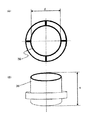
ライナー34の表面は、図6(A)及び(B)に示すように溝を有していることが、トナー粒子の表面改質を効率的におこなう上で好ましい。
The surface of the
分散ハンマー33の個数は、図3(A)及び(B)に示すように、回転バランスを考慮して、偶数個が好ましい。 As shown in FIGS. 3A and 3B, the number of the dispersion hammers 33 is preferably an even number in consideration of the rotational balance.
図1、図2及び図7に示す分級ローター35は、分散ローター32の回転方向と同方向に回転するのが、分級の効率を高め、トナー粒子の表面改質の効率を高める上で好ましい。分散ローターと分級ローターの回転方向を逆にすると、分級ローターに対する負荷が大きくなり、正常な運転が行えずトナー生産性という点から十分満足できるものではない。
The
微粉排出管は、分級ローター35により除去された微粉及び超微粉を装置外に排出するための微粉排出口45を有している。
The fine powder discharge pipe has a fine
該表面改質装置は、更に、図4(A)及び(B)に示すように、天板43に対して垂直な軸を有する案内手段としての円筒状のガイドリング36を本体ケーシング30内に有している。該ガイドリング36は、その上端が天板から所定距離離間して設けられており、分級ローター36の少なくとも一部を覆うようにガイドリングは、支持体により本体ケーシング30に固定されている。ガイドリング36の下端は分散ローター32の分散ハンマー33から所定距離離間して設けられる。該表面改質装置内において、分級ローター35と分散ローター32との間の空間が、ガイドリング36の外側の第一の空間47と、ガイドリング36の内側の第二の空間48とにガイドリング36によって二分される。第一の空間47は微粉砕物及び表面改質処理された粒子を分級ローター35へ導くための空間であり、第二の空間は微粉砕物及び表面改質処理された粒子を分散ローターへ導くための空間である。分散ローター32上に複数個設置された分散ハンマー33と、ライナー34との間隙部分が表面改質ゾーン49であり、該分級ローター35及び該分級ローター35の周辺部分が分級ゾーン50である。
The surface modification apparatus further includes a
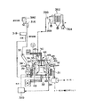
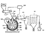
次に、本発明のトナーの製造方法に用いる回分式の表面改質装置による表面改質方法の概略を、図7を用いて説明する。 Next, an outline of a surface modification method using a batch type surface modification apparatus used in the toner production method of the present invention will be described with reference to FIG.
前述したように構成してなる回分式の表面改質装置は、図7に示す如く、原料ホッパー380に導入されら微粉砕物は、定量供給機315を経由して、投入管の原料投入口37から原料供給弁38を通って原料供給口39より装置内に供給される。表面改質装置には、冷風発生手段319で発生させた冷風を冷風導入口46から本体ケーシング内に供給し、さらに、冷水発生手段320からの冷水を冷水ジャッケト31に供給し、本体ケーシング内の温度を所定温度に調整する。供給された微粉砕物は、ブロアー364による吸引風量、分散ローター32の回転及び分級ローター35の回転により形成される旋回流により、円筒状のガイドリング36の外側の第一の空間47を旋回しながら分級ローター35近傍の分級ゾーン50に到達して分級処理が行われる。本体ケーシング30内に形成される旋回流の向きは、分散ローター32及び分級ローター35の回転方向と同じである。
As shown in FIG. 7, the batch type surface reforming apparatus configured as described above introduces the finely pulverized material introduced into the
分級ローター35によって除去されるべき微粉及び超微粉は、ブロワー364の吸引力より分級ローター35のスリット(図2参照)より吸引され微粉排出管の微粉排出口45及びサイクロン入口359を経由してサイクロン369及びバグ362に捕集される。微粉及び超微粉を除去された微粉砕物は第二の空間48を経由して分散ローター32近傍の表面改質ゾーン49に至り、分散ローター32に具備される分散ハンマー33と本体ケーシング30に具備されたライナー34によって粒子の表面改質処理が行われる。表面改質が行われた粒子はガイドリング36に沿って旋回しながら再び分級ローター35近傍に到達し、分級ローター35の分級により表面改質された粒子からの微粉及び超微粉の除去がおこなわれる。所定の時間処理を行った後、排出弁41を開き、表面改質装置から所定粒径以下の微粉及び超微粉が除かれた表面改質されたトナー粒子を取り出す。
The fine powder and super fine powder to be removed by the
所定の重量平均径に調整され、所定の粒度分布に調整され、さらに所定の円形度に表面改質されたトナー粒子は、トナー粒子の輸送手段321により外添剤の外添工程に移送される。 The toner particles adjusted to a predetermined weight average diameter, adjusted to a predetermined particle size distribution, and further surface-modified to a predetermined circularity are transferred to the external additive adding step by the toner particle transport means 321. .
本発明に用いられる表面改質装置は、鉛直方向下側より分散ローター32、微粉砕物(原料)の投入部39、分級ローター35及び微粉排出部を有している。従って、通常、分級ローター35の駆動部分(モーター等)は分級ローター35の更に上方に設けられ、分散ローター32の駆動部分は分散ローター32の更に下方に設ける。本発明で用いる表面改質装置は、例えば特開2001―259451号公報に記載されている分級ローター35のみを有するTSP分級機(ホソカワミクロン社製)の様に、微粉砕物(原料)を分級ローター35の鉛直上方向より供給することは困難である。
The surface reforming apparatus used in the present invention includes a
尚、該回分式の表面改質装置で発生した微粉体は、サイクロン、バグ等の捕集機器により回収し、トナー原料の配合工程に戻して再利用することがトナー生産性上好ましい。 It is preferable in terms of toner productivity that the fine powder generated by the batch-type surface reforming apparatus is collected by a collecting device such as a cyclone or a bag and returned to the toner raw material mixing step and reused.
本発明のトナーの製造方法の特徴は、
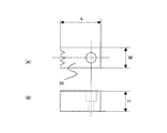
(1)図5に示す分散ハンマーの表面改質部=ライナーに対向している面に、複数の凹凸が設けられており、
(2)更には、該分散ハンマーの表面改質部に設けられている複数の凹凸は、その形状が波型形状であり、
(3)更には、該分散ハンマーの表面改質部に設けられている複数の凹凸は、複数の凸部と、該凸部と該凸部との間に形成される凹部とを有し、該凸部と該凸部との繰り返し距離が2.0mm以上8.0mm未満である回分式の表面改質機で、該微粉砕品(=被表面改質粒子)を表面改質することにより、
(4)小粒径で、円形度が高い表面改質粒子を収率良く得ることである。
The characteristics of the toner production method of the present invention are as follows:
(1) The surface modification portion of the dispersion hammer shown in FIG. 5 = a plurality of irregularities are provided on the surface facing the liner,
(2) Further, the plurality of irregularities provided in the surface modification portion of the dispersion hammer has a corrugated shape.
(3) Further, the plurality of irregularities provided in the surface modified portion of the dispersion hammer has a plurality of convex portions and concave portions formed between the convex portions and the convex portions, By surface-modifying the finely pulverized product (= surface-modified particles) with a batch-type surface reformer in which the repetition distance between the projections is 2.0 mm or more and less than 8.0 mm. ,
(4) To obtain surface-modified particles having a small particle size and high circularity with high yield.
即ち、本発明者が検討した結果、図5に示す分散ハンマーの表面改質部=ライナーに対向している面に複数の凹凸が設け、且つ、該分散ハンマーの表面改質部に設けられている複数の凹凸を、その形状が波型形状となるよう構成し、且つ、該分散ハンマーの表面改質部に設けられている複数の凹凸は、複数の凸部と、該凸部と該凸部との間に形成される凹部とを有し、該凸部と該凸部との繰り返し距離を2.0mm以上8.0mm未満とし、該分散ハンマーを組込んだ回分式の表面改質装置を適切な状態で運転することにより、シャープな粒度分布を持ち、且つ、円形度が高い表面改質粒子を収率良く得ることができる。更に、トナーの表面状態を任意にコントロールでき、良好な現像性、転写性並びにクリーニング性、及び安定した帯電性を有する、長寿命のトナーを得ることができる。 That is, as a result of examination by the present inventor, the surface modification portion of the dispersion hammer shown in FIG. 5 is provided with a plurality of irregularities on the surface facing the liner and provided on the surface modification portion of the dispersion hammer. The plurality of projections and depressions are configured so as to have a corrugated shape, and the plurality of projections and depressions provided on the surface modification portion of the dispersion hammer include a plurality of projections, the projections, and the projections. A batch-type surface reforming apparatus having a concave portion formed between the convex portion and the convex portion, the repetition distance between the convex portion and the convex portion being 2.0 mm or more and less than 8.0 mm, and incorporating the dispersion hammer Is operated in an appropriate state, surface-modified particles having a sharp particle size distribution and a high circularity can be obtained with high yield. Further, the surface state of the toner can be arbitrarily controlled, and a long-life toner having good developability, transferability, cleaning property, and stable chargeability can be obtained.
上記の理由として、表面改質粒子の表面形状状態は、表面改質装置内での表面改質粒子の運動状態に依存していると考えており、より円形度の高い表面改質粒子を、より収率良く得るためには、表面改質装置内の表面改質粒子の運動状態をコントロールすることが重要であると考えている。本発明において、表面改質工程で使用する表面改質装置を、図1に示す様な、回分式の表面改質装置とすることで、効率良く表面改質粒子が得られ、更に、該回分式表面改質装置内の分散ハンマー形状を前述した図5に示すようなタイプとすることにより、該回分式表面改質装置内における表面改質ゾーンでの被表面改質粒子の分散状態がより良好となると考えている。つまり該分散ハンマーの表面改質部に複数の凹凸部を設けることにより、該凹部内で気流の流れが発生し、この気流により、被表面改質粒子の分散状態が良好となり、該表面改質ゾーンでの表面改質が円滑に行われると考えている。更に、該回分式表面改質装置の各機器構成の関係や、表面改質ゾーンのおける運転条件を適切な状態に設定・制御することにより、所定粒径以下の微粉が除かれたシャープな粒度分布を持ち、且つ、円形度の高い表面改質粒子を、より収率良く得ることができる。 For the above reason, it is considered that the surface shape state of the surface modified particles depends on the motion state of the surface modified particles in the surface modifying apparatus. In order to obtain a higher yield, it is considered important to control the motion state of the surface modified particles in the surface modifying apparatus. In the present invention, the surface modification device used in the surface modification step is a batch type surface modification device as shown in FIG. 1, whereby surface modified particles can be obtained efficiently. By making the shape of the dispersion hammer in the surface modification device of the type shown in FIG. 5 described above, the dispersion state of the surface modified particles in the surface modification zone in the batch surface modification device is further improved. I think it will be good. That is, by providing a plurality of irregularities in the surface modification portion of the dispersion hammer, an air flow is generated in the recess, and this air flow improves the dispersion state of the surface modified particles, and the surface modification It is thought that surface modification in the zone is performed smoothly. In addition, by setting and controlling the relationship between each device configuration of the batch type surface reforming apparatus and the operating conditions in the surface reforming zone to an appropriate state, a sharp particle size from which fine particles of a predetermined particle size or less have been removed is removed. Surface-modified particles having a distribution and high circularity can be obtained with higher yield.
本発明者が検討した結果、該分散ハンマーと、該ライナーとの間の最小間隔を同じものとした場合において、該分散ハンマーの表面改質部に設けられている該凸部と該凸部との繰り返し距離及び凹部の深さを2.0mm未満とした場合、所望の平均円形度を持つ表面改質粒子が得られず、トナー生産性という点から十分満足できるものではない。これは、該分散ハンマーの表面改質部の該凸部と該凸部との繰り返し距離が狭く、該凹部の深さが浅いため、該凹部における気流の発生量が少なくなり、該表面改質ゾーンでの被表面改質粒子の分散が弱くなることで被表面改質粒子の運動量が低下するためと考えているまた、該凸部と該凸部との繰り返し距離及び凹部の深さが8.0mmを超えると、所望の平均円形度を持つ表面改質粒子が得られず、こちらもトナー生産性という点から十分満足できるものではない。これは、該分散ハンマーの表面改質部の該凸部と該凸部との繰り返し距離が広く、該凹部の深さが深いため、結果的に、該分散ハンマーと、該ライナーとの間の最小間隔が広い状態となり、表面改質ゾーンでの被表面改質粒子の運動量が低下するためと考えている As a result of the study by the present inventors, when the minimum distance between the dispersion hammer and the liner is the same, the projections and the projections provided in the surface modification portion of the dispersion hammer When the repeating distance and the depth of the recess are less than 2.0 mm, surface-modified particles having a desired average circularity cannot be obtained, which is not satisfactory from the viewpoint of toner productivity. This is because the repetition distance between the convex portion and the convex portion of the surface modification portion of the dispersion hammer is narrow and the depth of the concave portion is shallow, so that the amount of air flow in the concave portion is reduced, and the surface modification It is considered that the momentum of the surface modified particles decreases due to the weak dispersion of the surface modified particles in the zone. In addition, the repetition distance between the convex portions and the convex portions and the depth of the concave portions are 8 If the thickness exceeds 0.0 mm, surface-modified particles having a desired average circularity cannot be obtained, which is also not satisfactory from the viewpoint of toner productivity. This is because the repetitive distance between the convex portion and the convex portion of the surface modified portion of the dispersion hammer is wide and the depth of the concave portion is deep, and as a result, there is a gap between the dispersion hammer and the liner. This is because the minimum distance becomes wide and the momentum of the surface modified particles in the surface modification zone decreases.
従って、該分散ハンマーの表面改質部に設けられている該凸部と該凸部との繰り返し距離を2.0mm以上8.0mm以下とすることが好ましく、該凹部の深さhを2.0mm以上8.0mm以下とすることが、所定粒径以下の微粉が除かれたシャープな粒度分布を持ち、且つ、円形度の高い表面改質粒子を、より収率良く得る上で好ましい。 Therefore, it is preferable that the repetition distance between the convex portion provided on the surface modified portion of the dispersing hammer and the convex portion is 2.0 mm or more and 8.0 mm or less, and the depth h of the concave portion is 2. It is preferable that the particle size is 0 mm or more and 8.0 mm or less in order to obtain surface-modified particles having a sharp particle size distribution from which fine powder having a predetermined particle size or less is removed and having a high degree of circularity with higher yield.
更に本発明のトナーの製造方法においては、該分散ハンマー及び/又はライナーの表面が、少なくとも炭化クロムを含有するクロム合金めっきでコーティングされていることが好ましい。 Furthermore, in the toner production method of the present invention, it is preferable that the surface of the dispersing hammer and / or liner is coated with a chromium alloy plating containing at least chromium carbide.
該分散ハンマー及び/又はライナーの母材には、S45Cなどの炭素鋼やSCM材などのクロムモリブデン鋼などが用いられることが多い。これらの母材表面をクロム合金でコーティングすることにより、表面硬さが大きく、耐摩耗性が高くなり、長寿命の分散ハンマーやライナーとなる。ここで、クロム合金に存在する、分子間結合力の強い炭化クロム(Cr23C6)が表層からある程度の深度以上まで、具体的には5μm以上の深度まで、存在することで母材表面との密着性を高め、剥離やクラックといった現象の発生頻度を極力少なくすることができる。 As the base material of the dispersing hammer and / or liner, carbon steel such as S45C or chromium molybdenum steel such as SCM material is often used. By coating the surface of these base materials with a chromium alloy, the surface hardness is increased, the wear resistance is increased, and a long-life dispersion hammer or liner is obtained. Here, chromium carbide (Cr 23 C 6 ) present in the chromium alloy having a strong intermolecular bonding force exists from the surface layer to a certain depth or more, specifically, to a depth of 5 μm or more. It is possible to improve the adhesion of the film and to reduce the frequency of occurrence of phenomena such as peeling and cracking as much as possible.
本発明において、炭化クロムを含有するクロム合金の母材表面へのコーティングは「めっき」により処理し、表面を均一且つ滑らかに仕上げ、摩擦係数を小さくして耐摩耗性を向上させることが可能となる。このようなめっき処理としては、例えば、ダイクロン処理(千代田第一工業(株))があげられる。 In the present invention, the coating of the chromium alloy containing chromium carbide on the base material surface is processed by “plating”, and the surface can be finished uniformly and smoothly, and the friction coefficient can be reduced to improve the wear resistance. Become. An example of such a plating process is a dicron process (Chiyoda Daiichi Kogyo Co., Ltd.).
更に本発明のトナーの製造方法においては、表面改質装置の原料投入口37に供給される微粉砕物(原料)が特定の粒度分布を有していることが好ましい。更に、表面改質装置による処理後のトナー粒子(表面改質粒子)の超微粉量が所定量に制御されていることが好ましい。
Furthermore, in the toner production method of the present invention, it is preferable that the finely pulverized product (raw material) supplied to the
本発明では、微粉砕物の重量平均粒径が3.5〜9.0μmであり、且つ粒径が4.00μm以下の粒子の割合が50〜80個数%であり、得られるトナー粒子の重量平均粒径が4.5〜9.0μmであり且つ粒径が4.00μm以下の粒子(微粉)の割合が5〜40個数%であり、更に、トナー粒子のフロー式粒子像測定装置で計測される円相当径0.6μm以上400μm以下の粒子の個数基準の粒径分布において、円相当径が0.6μm以上2μm未満(超微粉)のトナー粒子の割合が0〜10個数%であることが好ましい。 In the present invention, the weight average particle diameter of the finely pulverized product is 3.5 to 9.0 μm, and the ratio of particles having a particle diameter of 4.00 μm or less is 50 to 80% by number. The ratio of particles (fine powder) having an average particle diameter of 4.5 to 9.0 μm and a particle diameter of 4.00 μm or less is 5 to 40% by number, and further measured with a flow particle image measuring device for toner particles. In the particle diameter distribution based on the number of particles having an equivalent circle diameter of 0.6 μm or more and 400 μm or less, the ratio of toner particles having an equivalent circle diameter of 0.6 μm or more and less than 2 μm (ultra fine powder) is 0 to 10% by number. Is preferred.
微粉砕物の粒度分布は分級効率に影響を与える。微粉砕物中に細かい粒子が多い場合は、分級時間が長くなり、本来分級除去しなくてもよい粒子までも分級により除去されるので分級収率の低下の原因となることがある。更には、分級を行う際に微粉砕物の凝集性が高くなり、トナー粒子中より本来除去すべき超微粉が除去できなくなる場合が生じやすく、得られるトナーは、かぶりが発生しやすくなる。 The particle size distribution of the finely pulverized product affects the classification efficiency. When there are many fine particles in the finely pulverized product, the classification time becomes long, and even particles that do not need to be classified and removed are removed by classification, which may cause a reduction in classification yield. Furthermore, the cohesiveness of the finely pulverized product becomes high when classification is performed, and it may be difficult to remove the ultrafine powder that should be removed from the toner particles, and the resulting toner is likely to be fogged.
従って、微粉砕物の重量平均粒径が3.5μmより小さい場合は粒子間の凝集性が高くなり効率的な分級が困難となることがある。また、微粉砕物の重量平均粒径が9.0μmより大きい場合は、得られるトナーは、鮮明な画質を形成することが難しくなり好ましくない。また、粒径が4.00μm以下の粒子の割合が50個数%未満の場合は、得られるトナーは鮮明な画質を形成することが難しくなり好ましくない。一方、粒径が4.00μm以下の粒子の割合が80個数%より多すぎる場合は微粉砕物の凝集性が高くなり良好な分級収率を得ることが困難となる。更に、粒径が4.00μm以下の粒子の割合が80個数%より多すぎる場合は、微粉砕物中の超微粉が増加する傾向にあり好ましくない。微粉砕物中における粒径が4.00μm以下の粒子の割合は、好ましくは55〜75個数%である。 Therefore, when the weight average particle size of the finely pulverized product is smaller than 3.5 μm, the cohesiveness between the particles becomes high and efficient classification may be difficult. On the other hand, when the weight average particle size of the finely pulverized product is larger than 9.0 μm, it is not preferable for the obtained toner to form a clear image quality. On the other hand, when the ratio of particles having a particle diameter of 4.00 μm or less is less than 50% by number, it is difficult to form a clear image with the obtained toner. On the other hand, when the proportion of particles having a particle size of 4.00 μm or less is more than 80% by number, the cohesiveness of the finely pulverized product becomes high and it is difficult to obtain a good classification yield. Furthermore, when the ratio of particles having a particle size of 4.00 μm or less is more than 80% by number, the ultra fine powder in the finely pulverized product tends to increase, which is not preferable. The proportion of particles having a particle size of 4.00 μm or less in the finely pulverized product is preferably 55 to 75% by number.
尚、粒度分布の測定は種々の方法によって測定できるが、本発明においてはコールターカウンターのマルチサイザーを用いて行った。 The particle size distribution can be measured by various methods, but in the present invention, a Coulter counter multisizer was used.
測定装置としては、コールターカウンターのマルチサイザーII型或いはIIe型(コールター社製)を用い、個数分布、体積分布を出力するインターフェイス(日科機製)及び一般的なパーソナルコンピューターを接続し、電解液は特級または1級塩化ナトリウムを用いて1%NaCl水溶液を調製する。測定法としては前記電解水溶液100〜150ml中に分散剤として界面活性剤(好ましくはアルキルベンゼンスルホン酸塩)を0.1〜5ml加え、更に測定試料を2〜20mg加える。試料を懸濁した電解液は超音波分散器で約1〜3分間分散処理を行い、前記コールターカウンターのマルチサイザーII型により、100μmアパーチャーを用いて測定する。トナーの体積、個数を測定して、体積分布と個数分布とを算出し、体積分布から求めた重量基準の重量平均径を求める。 As a measuring device, a multisizer type II or type IIe (manufactured by Coulter Co.) of a Coulter counter is used, and an interface (manufactured by Nikkiki) that outputs number distribution and volume distribution is connected to a general personal computer. A 1% NaCl aqueous solution is prepared using special grade or first grade sodium chloride. As a measuring method, 0.1 to 5 ml of a surfactant (preferably alkylbenzene sulfonate) is added as a dispersant to 100 to 150 ml of the electrolytic aqueous solution, and 2 to 20 mg of a measurement sample is further added. The electrolytic solution in which the sample is suspended is subjected to a dispersion treatment with an ultrasonic disperser for about 1 to 3 minutes, and measured using a Coulter counter Multisizer II type with a 100 μm aperture. The volume and number of toners are measured to calculate a volume distribution and a number distribution, and a weight-based weight average diameter obtained from the volume distribution is obtained.
更に本発明の表面改質装置により、処理がなされたトナー粒子のフロー式粒子像測定装置で計測される、円相当径が0.6μm以上400μm以下の粒子の個数基準の粒径分布において、円相当径が0.6μm以上2μm未満のトナー粒子(超微粉)の割合を0〜10個数%の範囲に制御することが好ましい。円相当径が0.6μm以上2μm未満のトナー粒子の割合が10個数%より多い場合は、得られるトナーはかぶり現象が発生しやすいため好ましくない。円相当径が0.6μm以上2μm未満のトナー粒子の割合は、より好ましくは8個数%以下である。 Further, in the particle size distribution based on the number of particles having an equivalent circle diameter of 0.6 μm or more and 400 μm or less, which is measured by a flow type particle image measuring apparatus for toner particles processed by the surface modification device of the present invention, It is preferable to control the ratio of toner particles (ultrafine powder) having an equivalent diameter of 0.6 μm or more and less than 2 μm to a range of 0 to 10% by number. When the proportion of toner particles having an equivalent circle diameter of 0.6 μm or more and less than 2 μm is more than 10% by number, the obtained toner is not preferable because fog phenomenon easily occurs. The ratio of toner particles having an equivalent circle diameter of 0.6 μm or more and less than 2 μm is more preferably 8% by number or less.
更に本発明の表面改質装置により、処理がなされたトナー粒子のフロー式粒子像測定装置で計測される平均円形度aは、0.935乃至0.980であることが好ましい。 Further, the average circularity a measured by the flow type particle image measuring apparatus for the toner particles processed by the surface modifying apparatus of the present invention is preferably 0.935 to 0.980.
本発明者が検討した結果、前記平均円形度aが0.935以上、好ましくは0.940以上、より好ましくは、0.945以上とすることにより、現像性を損なうことなく、転写効率が向上し、ドット再現性が良くなることが分かった。また外添剤による流動性付与の効果も大きくなることが分かった。 As a result of studies by the present inventors, the average circularity a is 0.935 or more, preferably 0.940 or more, more preferably 0.945 or more, thereby improving transfer efficiency without impairing developability. It was found that the dot reproducibility was improved. Moreover, it turned out that the effect of the fluidity | liquidity provision by an external additive becomes large.
前記平均円形度が0.935未満の場合は、外添剤による流動性付与の効果が小さくなるため、トナーの流動性が低下し、トナーの帯電量にバラツキが生じ、転写効率の低下やドット再現性の低下が生じやすくなる。 When the average circularity is less than 0.935, the fluidity imparting effect by the external additive is reduced, so that the toner fluidity is lowered, the toner charge amount varies, the transfer efficiency is lowered, and the dot A decrease in reproducibility tends to occur.
本発明における「表面改質」とは、粒子表面の凸凹を円滑にすることであり、粒子の外観形状を球形に近づけることをいう。このような本発明の表面改質粒子の表面改質の度合いを示すものとして、本発明においては平均円形度をその指標とする。 “Surface modification” in the present invention means smoothing the unevenness of the particle surface, and means that the appearance shape of the particle is close to a sphere. As an indicator of the degree of surface modification of the surface modified particles of the present invention, the average circularity is used as an index in the present invention.
本発明における平均円形度は、フロー式粒子像測定装置「FPIA−2100型」(シスメックス社製)を用いて測定を行い、下式を用いて算出する。 The average circularity in the present invention is measured using a flow type particle image measuring device “FPIA-2100 type” (manufactured by Sysmex Corporation), and is calculated using the following equation.

ここで、「粒子投影面積」とは二値化された粒子像の面積であり、「粒子投影像の周囲長」とは該粒子像のエッジ点を結んで得られる輪郭線の長さと定義する。測定は、512×512の画像処理解像度(0.3μm×0.3μmの画素)で画像処理した時の粒子像の周囲長を用いる。 Here, “particle projection area” is the area of the binarized particle image, and “perimeter of the particle projection image” is defined as the length of the contour line obtained by connecting the edge points of the particle image. . The measurement uses the perimeter of the particle image when image processing is performed at an image processing resolution of 512 × 512 (pixels of 0.3 μm × 0.3 μm).
本発明における円形度は粒子の凹凸の度合いを示す指標であり、粒子が完全な球形の場合に1.000を示し、表面形状が複雑になる程、円形度は小さな値となる。 In the present invention, the circularity is an index indicating the degree of unevenness of the particles, and is 1.000 when the particles are perfectly spherical. The more complicated the surface shape, the smaller the circularity.
また、円形度頻度分布の平均値を意味する平均円形度Cは、粒度分布の分割点iでの円形度(中心値)をci、測定粒子数をmとすると、次式から算出される。 The average circularity C, which means the average value of the circularity frequency distribution, is calculated from the following equation, where ci is the circularity (center value) at the dividing point i of the particle size distribution and m is the number of measured particles.
![]()
![]()
円形度標準偏差SDは、平均円形度C、各粒子における円形度ci、測定粒子数をmとすると次式から算出される。 The circularity standard deviation SD is calculated from the following equation where the average circularity C, the circularity ci of each particle, and the number of measured particles are m.
![]()
![]()
本発明で用いている測定装置である「FPIA−2100」は、各粒子の円形度を算出後、平均円形度及び円形度標準偏差の算出に当たって、得られた円形度によって、粒子を円形度0.4〜1.0を0.01ごとに等分割したクラスに分け、その分割点の中心値と測定粒子数を用いて平均円形度及び円形度標準偏差の算出を行う。 “FPIA-2100”, which is a measuring device used in the present invention, calculates the circularity of each particle, and then calculates the average circularity and the circularity standard deviation. .4 to 1.0 are divided into classes equally divided every 0.01, and the average circularity and the circularity standard deviation are calculated using the center value of the division points and the number of measured particles.
具体的な測定方法としては、容器中に予め不純固形物などを除去したイオン交換水10mlを用意し、その中に分散剤として界面活性剤(好ましくはアルキルベンゼンスルホン酸塩)を加えた後、更に測定試料を0.02g加え、均一に分散させる。分散させる手段としては、超音波分散機「Tetora150型」(日科機バイオス社製)を用い、2分間分散処理を行い、測定用の分散液とする。その際、該分散液の温度が40℃以上とならない様に適宜冷却する。また、円形度のバラツキを抑えるため、フロー式粒子像分析装置FPIA−2100の機内温度が26〜27℃になるよう装置の設置環境を23℃±0.5℃にコントロールし、一定時間おきに、好ましくは2時間おきに2μmラテックス粒子を用いて自動焦点調整を行う。 As a specific measuring method, 10 ml of ion-exchanged water from which impure solids have been removed in advance is prepared in a container, and after adding a surfactant (preferably alkylbenzene sulfonate) as a dispersant, Add 0.02 g of the measurement sample and disperse it uniformly. As a means for dispersion, an ultrasonic disperser “Tetora 150 type” (manufactured by Nikka Ki Bios Co., Ltd.) is used, and dispersion treatment is performed for 2 minutes to obtain a dispersion for measurement. In that case, it cools suitably so that the temperature of this dispersion may not be 40 degreeC or more. In order to suppress variation in circularity, the installation environment of the apparatus is controlled at 23 ° C. ± 0.5 ° C. so that the temperature inside the flow type particle image analyzer FPIA-2100 is 26 to 27 ° C. Preferably, autofocus is performed using 2 μm latex particles every 2 hours.
超音波発振器による分散条件
装置:UH−150(株式会社エス・エム・テー社製)
OUTPUT レベル:5
コンスタントモード
Dispersion condition device by ultrasonic oscillator : UH-150 (manufactured by SMT Co., Ltd.)
OUTPUT level: 5
Constant mode
粒子の円形度測定には、前記フロー式粒子像測定装置を用い、測定時のトナー粒子濃度が3000〜1万個/μlとなる様に該分散液濃度を再調整し、粒子を1000個以上計測する。計測後、このデータを用いて、円相当径2μm未満のデータをカットして、粒子の平均円形度を求める。 For the measurement of the circularity of the particles, the flow type particle image measuring device is used, the concentration of the dispersion is readjusted so that the toner particle concentration at the time of measurement is 3000 to 10,000 / μl, and 1000 or more particles are obtained. measure. After the measurement, using this data, data having an equivalent circle diameter of less than 2 μm is cut to determine the average circularity of the particles.
更に本発明で用いている測定装置「FPIA−2100」は、トナー又はトナー粒子の形状を算出するために用いられていた「FPIA−1000」と比較して、処理粒子画像の倍率の向上、さらに取り込んだ画像の処理解像度を向上(256×256→512×512)させることにより粒子の形状測定の精度が上がっており、それにより微粒子のより確実な補足を達成している装置である。従って、本発明のように、より正確に形状を測定する必要がある場合には、FPIA2100の方が有用である。 Furthermore, the measurement device “FPIA-2100” used in the present invention improves the magnification of the processed particle image as compared with “FPIA-1000” used to calculate the shape of the toner or toner particles. By improving the processing resolution of the captured image (256 × 256 → 512 × 512), the accuracy of particle shape measurement is improved, thereby achieving more reliable capture of fine particles. Therefore, the FPIA 2100 is more useful when the shape needs to be measured more accurately as in the present invention.
本発明における測定の概略は、以下の通りである。 The outline of the measurement in the present invention is as follows.
試料分散液は、フラットで扁平なフローセル(厚み約200μm)の流路(流れ方向に沿って広がっている)を通過させる。フローセルの厚みに対して交差して通過する光路を形成するように、ストロボとCCDカメラが、フローセルに対して、相互に反対側に位置するように装着される。試料分散液が流れている間に、ストロボ光がフローセルを流れている粒子の画像を得るために1/30秒間隔で照射され、その結果、それぞれの粒子は、フローセルに平行な一定範囲を有する2次元画像として撮影される。それぞれの粒子の2次元画像の面積から、同一の面積を有する円の直径を円相当径として算出する。それぞれの粒子の2次元画像の投影面積及び投影像の周囲長から上記の円形度算出式を用いて各粒子の円形度を算出する。 The sample dispersion is passed through a flow path (expanded along the flow direction) of a flat and flat flow cell (thickness: about 200 μm). The strobe and the CCD camera are mounted on the flow cell so as to be opposite to each other so as to form an optical path that passes through the thickness of the flow cell. While the sample dispersion is flowing, strobe light is irradiated at 1/30 second intervals to obtain an image of the particles flowing through the flow cell, so that each particle has a certain range parallel to the flow cell. Photographed as a two-dimensional image. From the area of the two-dimensional image of each particle, the diameter of a circle having the same area is calculated as the equivalent circle diameter. The circularity of each particle is calculated from the projected area of the two-dimensional image of each particle and the perimeter of the projected image using the above circularity calculation formula.
また、本発明においては、フロー式粒子像測定装置で計測される、円相当径が0.6μm以上400μm以下の(表面改質処理後の)トナー粒子の個数基準の粒径分布において、円相当径が0.6μm以上2μm未満のトナー粒子の割合が0〜10個数%であることが好ましい。このような円相当径を有するトナー粒子の割合は0〜10個数%であることが好ましく、0〜8個数%であることがより好ましく、0〜5個数%未満であることがさらに好ましい。円相当径が0.6μm以上2μm未満のトナー粒子は、トナーの現像性、特にカブリ特性に大きな影響を与える。このような微粒子トナーは過度に高い帯電性を有しており、トナーの現像時に過剰に現像されやすく、画像上にカブリとして現れる。しかし、本発明においてはこのような微粒子トナーの比率が少ないことによってカブリを低減することができる。 Further, in the present invention, in the particle size distribution based on the number of toner particles (after the surface modification treatment) having a circle equivalent diameter of 0.6 μm or more and 400 μm or less, which is measured by a flow type particle image measuring device, it is equivalent to a circle. The proportion of toner particles having a diameter of 0.6 μm or more and less than 2 μm is preferably 0 to 10% by number. The ratio of toner particles having such an equivalent circle diameter is preferably 0 to 10% by number, more preferably 0 to 8% by number, and further preferably 0 to less than 5% by number. Toner particles having an equivalent circle diameter of 0.6 μm or more and less than 2 μm have a great influence on the developability of the toner, in particular, the fog characteristics. Such a fine particle toner has an excessively high chargeability, is easily developed excessively at the time of developing the toner, and appears as fog on the image. However, in the present invention, the fog can be reduced by the small proportion of the fine particle toner.
また、本発明で好適に用いられる評価基準として、トナー粒子中の超微粉量を用いることができる。この超微粉量はトナー画像におけるかぶりと相関関係があることが認められているからである。超微粉量はFPIA−2100により測定された粒度分布における円相当径が2.0μm以下の粒子の個数%により判断する。円相当径が2.0μm以下の粒子の存在量が10個数%以下であることが、画像評価におけるかぶりのレベルを良好に維持していく上で好ましい。 Further, the amount of ultrafine powder in the toner particles can be used as an evaluation standard that is preferably used in the present invention. This is because it is recognized that the amount of ultrafine powder has a correlation with the fog in the toner image. The amount of ultrafine powder is determined by the number% of particles having an equivalent circle diameter of 2.0 μm or less in the particle size distribution measured by FPIA-2100. The abundance of particles having an equivalent circle diameter of 2.0 μm or less is preferably 10% by number or less in order to maintain a good fog level in image evaluation.
また、本発明においては、該回分式の表面改質装置によって得られた表面改質粒子であるトナー粒子の、メタノール45体積%水溶液における透過率(%)が、20%以上70%未満の範囲にあることにあることが好ましい。 Further, in the present invention, the transmittance (%) of the toner particles, which are the surface modified particles obtained by the batch type surface modifying apparatus, in a 45 volume% methanol aqueous solution is in the range of 20% or more and less than 70%. It is preferable that it exists in.
本発明のトナーは、トナー中にワックスを含有しているため、トナー粒子表面において、少なくともワックスが存在している。トナー表面のワックスが少ない場合、定着時における離型効果が現れにくく、省エネの観点から望まれる低温定着性の効果が減少する。また、トナー表面にワックスが多く存在する場合、帯電付与部材にワックスが汚染し、例えば現像スリーブ上に融着することで高抵抗化し、現像にかかる実際の現像バイアスの効力が下がり、しいては画像濃度が低下し現像耐久性が悪化する場合がある。このように、トナー中にワックスを含有させる場合、トナー表面のワックス量をコントロールすることが重要である。 Since the toner of the present invention contains a wax in the toner, at least the wax is present on the surface of the toner particles. When the wax on the toner surface is small, the releasing effect at the time of fixing hardly appears, and the low temperature fixing effect desired from the viewpoint of energy saving decreases. In addition, when there is a lot of wax on the toner surface, the charge imparting member is contaminated with wax, and, for example, the resistance is increased by fusing on the developing sleeve, and the effectiveness of the actual development bias for development is reduced. In some cases, the image density decreases and the development durability deteriorates. As described above, when the wax is contained in the toner, it is important to control the amount of wax on the toner surface.
本発明者が検討した結果、表面改質粒子であるトナー粒子の、メタノール45体積%水溶液における透過率(%)が、20%より小さい時には、トナー表面に結着樹脂と親水性着色剤、例えば染料やC.Bなどが偏って存在しているために、帯電の環境差が大きいものとなると考えられる。これは感光ドラムのコントラストを十分にとることができなくなるため、画像濃度変動が大きくなりやすく、且つ諧調性に乏しい画像となるため、フルカラーの画像においては、色再現性など非常に悪いものとなる。逆に、メタノール45体積%水溶液における透過率(%)が、70%より大きい時には、トナー表面に有機顔料やワックスなどの離型剤が多く存在しているために、絶縁性の物質同士が集まってはいるが帯電能がかなり違うため、トナーの帯電のブロード化を起こしてしまうと考えられる。これは連続複写しているうちに、トナー同士の電荷の授受も少ないため、帯電の高低差が開き、ついにはカブリやトナー飛散を生じてしまう。 As a result of the study by the present inventors, when the transmittance (%) of the toner particles as surface modified particles in a 45 volume% methanol aqueous solution is smaller than 20%, a binder resin and a hydrophilic colorant, for example, on the toner surface, for example, Dyes and C.I. Since B and the like are biased, it is considered that the difference in charging environment is large. This makes it impossible to obtain a sufficient contrast of the photosensitive drum, so that the image density fluctuation is likely to be large and the gradation is poor. Therefore, in a full-color image, color reproducibility is very poor. . Conversely, when the transmittance (%) in a 45% by volume methanol aqueous solution is greater than 70%, there are many release agents such as organic pigments and wax on the toner surface, so that insulating substances gather together. However, it is considered that the charging ability of the toner is broadened because the charging ability is quite different. This is because there is little transfer of charge between toners during continuous copying, so the difference in charge level opens, and eventually fogging and toner scattering occur.
即ち、表面改質粒子であるトナー粒子の、メタノール45体積%水溶液における透過率(%)が、20%以上70%未満の範囲にすることにより、トナー表面に各種材料をバランスよく存在させることで、良好な現像性、転写性並びにクリーニング性、及び安定した帯電性を有する、長寿命のトナーを得ることができる。 That is, by making the transmittance (%) of toner particles as surface modified particles in a 45 volume% methanol aqueous solution in a range of 20% or more and less than 70%, various materials can be present on the toner surface in a balanced manner. Thus, a long-life toner having good developability, transferability, cleaning property, and stable chargeability can be obtained.
トナー表面のワックス量は、メタノール45体積%水溶液における透過率(%)を測ることにより、簡易且つ精度の高く測定出来る。 The amount of wax on the toner surface can be measured easily and with high accuracy by measuring the transmittance (%) in a 45% by volume aqueous solution of methanol.
この測定方法は、トナー粒子を一度メタノール水混合溶媒中で強制分散させて、トナー粒子一粒一粒の表面ワックス量の特徴を出やすくした上で、一定時間後の透過率を測定することで、トナー表面のワックス量を正確に把握できるものである。 In this measurement method, toner particles are forcibly dispersed once in a methanol / water mixture solvent to easily reveal the characteristics of the surface wax amount of each toner particle, and then the transmittance after a certain time is measured. The amount of wax on the toner surface can be accurately grasped.
本発明においては、メタノール45体積%水溶液における透過率を、以下の手順で測定した。 In this invention, the transmittance | permeability in 45 volume% methanol aqueous solution was measured in the following procedures.
(1)トナー分散液の調製
メタノール:水の体積混合比が45:55の水溶液を作製する。この水溶液10mlを30mlのサンプルビン(日電理化硝子:SV−30)に入れ、トナー20mgを液面上に侵しビンのフタをする。その後、ヤヨイ式振とう器(モデル:YS−LD)により2.5S−1で5秒間振とうさせる。この時、振とうする角度は、振とう器の真上(垂直)を0度とすると、前方に15度、後方に20度、振とうする支柱が動くようにする。サンプルビンは支柱の先に取り付けた固定用ホルダー(サンプルビンの蓋が支柱中心の延長上に固定されたもの)に固定する。サンプルビンを取り出した後、30秒後の分散液を測定用分散液とする。
(1) Preparation of toner dispersion An aqueous solution having a volume mixing ratio of methanol: water of 45:55 is prepared. 10 ml of this aqueous solution is placed in a 30 ml sample bottle (Nippon Denka Glass: SV-30), and 20 mg of toner is impregnated on the liquid surface to cover the bottle. Then, it is made to shake at 2.5S-1 for 5 seconds with a Yayoi type shaker (model: YS-LD). At this time, the angle of shaking is such that the shaking column moves 15 degrees forward and 20 degrees backward, assuming that the vertical (vertical) of the shaker is 0 degree. The sample bottle is fixed to a fixing holder (with the sample bottle lid fixed on the extension at the center of the column) attached to the tip of the column. After removing the sample bottle, the dispersion after 30 seconds is used as a dispersion for measurement.
(2)透過率測定
(1)で得た分散液を1cm角の石英セルに入れて分光光度計MPS2000(島津製作所社製)を用いて、10分後の分散液の波長600nmにおける透過率(%)を測定する。
透過率(%)=I/I0×100 I:入射光束、I0:透過光束
(2) Transmittance measurement The dispersion obtained in (1) was placed in a 1 cm square quartz cell, and the transmittance at a wavelength of 600 nm of the dispersion after 10 minutes using a spectrophotometer MPS2000 (manufactured by Shimadzu Corporation) ( %).
Transmittance (%) = I / I0 × 100 I: incident light flux, I0: transmitted light flux
本発明のトナーの製造方法においては、該回分式の表面改質装置における表面改質時間としては、5秒以上180秒以下、より好ましくは15秒以上150秒以下、更に好ましくは15秒以上120秒以下であることが好ましい。該表面改質時間が5秒未満の場合、表面改質時間が短時間過ぎるため、所望の円形度及び平均面粗さを持つ表面改質粒子が得られずトナー品質上好ましくない。また、表面改質時間が180秒を超える場合、表面改質時間が長時間過ぎるため、表面改質時に発生する熱による表面変質や、機内融着の発生、及び処理能力の低下を招くので、トナー生産性という点から十分満足できるものではない。 In the toner production method of the present invention, the surface modification time in the batch type surface modification apparatus is 5 seconds or more and 180 seconds or less, more preferably 15 seconds or more and 150 seconds or less, and further preferably 15 seconds or more and 120 seconds. It is preferable that it is below second. When the surface modification time is less than 5 seconds, since the surface modification time is too short, surface modified particles having a desired circularity and average surface roughness cannot be obtained, which is not preferable in terms of toner quality. In addition, when the surface modification time exceeds 180 seconds, the surface modification time is too long, so it causes surface deterioration due to heat generated during surface modification, occurrence of in-machine fusion, and reduction in processing capacity. This is not satisfactory from the viewpoint of toner productivity.
更に、本発明のトナーの製造方法においては、該回分式表面改質装置内に導入する冷風温度T1を5℃以下、より好ましくは0℃以下、更に好ましくは−5℃以下とすることが好ましい。該回分式表面改質装置内に導入する冷風温度T1を5℃以下より好ましくは0℃以下、更に好ましくは−5℃以下とすることにより、表面改質時に発生する熱による表面変質や、機内融着を防止することができる。該回分式表面改質装置内に導入する冷風温度T1が5℃以上を超えるものとすると、表面改質時に発生する熱による表面変質や、機内融着を起こしやすいので、トナー生産性という点から十分満足できるものではない。 Further, in the toner production method of the present invention, the cold air temperature T1 introduced into the batch type surface reforming apparatus is preferably 5 ° C. or less, more preferably 0 ° C. or less, and further preferably −5 ° C. or less. . By setting the cold air temperature T1 introduced into the batch type surface reforming apparatus to 5 ° C. or less, preferably 0 ° C. or less, more preferably −5 ° C. or less, surface alteration due to heat generated during surface modification, Fusion can be prevented. If the cold air temperature T1 introduced into the batch-type surface reforming apparatus exceeds 5 ° C. or more, surface modification due to heat generated during the surface modification or in-machine fusion is likely to occur. It is not satisfactory enough.
また、該回分式表面改質装置内に導入する冷風の発生装置で使用する冷媒としては、地球全体の環境問題という点から代替フロンが好ましい。 In addition, as a refrigerant used in the cold air generator introduced into the batch type surface reforming apparatus, an alternative chlorofluorocarbon is preferable from the viewpoint of environmental problems of the entire earth.
代替フロンとしては、R134A、R404A、R407C、R410A、R507A、R717等が挙げられるが、この中で、省エネルギー性や安全性という点から、特にR404Aが好ましい。 Alternative CFCs include R134A, R404A, R407C, R410A, R507A, R717, etc. Among them, R404A is particularly preferable from the viewpoint of energy saving and safety.
尚、該回分式表面改質装置内に導入する冷風は、装置内の結露防止という面から、除湿したものであることがトナー生産性上好ましい。除湿装置としては公知のものが使用できる。給気露点温度としては、−15℃以下が好ましく、更には−20℃以下が好ましい。 The cold air introduced into the batch type surface reforming apparatus is preferably dehumidified from the viewpoint of preventing condensation in the apparatus from the viewpoint of toner productivity. A well-known thing can be used as a dehumidifier. The supply air dew point temperature is preferably −15 ° C. or lower, and more preferably −20 ° C. or lower.
更に、本発明のトナーの製造方法においては、該回分式表面改質装置内は、機内冷却用のジャケットを具備しており、該ジャケットに冷媒(好ましくは冷却水、更に好ましくはエチレングリコール等の不凍液)を通しながら被表面改質粒子を表面改質処理することが好ましい。該ジャケットによる機内冷却により、表面改質時における熱による表面変質や機内融着を防止することができる。 Further, in the toner production method of the present invention, the batch type surface reforming apparatus is provided with a jacket for cooling inside the apparatus, and a refrigerant (preferably cooling water, more preferably ethylene glycol or the like) is provided in the jacket. The surface-modified particles are preferably subjected to a surface modification treatment while passing through an antifreeze solution. In-machine cooling by the jacket can prevent surface alteration and in-machine fusion due to heat during surface modification.
尚、該回分式表面改質装置のジャケット内に通す冷媒の温度は5℃以下、より好ましくは0℃以下、更に好ましくは−5℃以下とすることが好ましい。該回分式表面改質装置内のジャケット内に通す冷媒の温度を5℃以下、より好ましくは0℃以下、更に好ましくは−5℃以下とすることにより、表面改質時に発生する熱による表面変質や、機内融着を防止することができる。該冷却ジャケット内に導入する冷媒の温度が5℃を超えるものとすると、表面改質時に発生する熱による表面変質や、機内融着を起こしやすいので、トナー生産性という点から十分満足できるものではない。 The temperature of the refrigerant passed through the jacket of the batch type surface reformer is preferably 5 ° C. or less, more preferably 0 ° C. or less, and further preferably −5 ° C. or less. By changing the temperature of the refrigerant passed through the jacket in the batch type surface reforming apparatus to 5 ° C. or less, more preferably 0 ° C. or less, and further preferably −5 ° C. or less, surface alteration due to heat generated during the surface modification In addition, in-machine fusion can be prevented. If the temperature of the refrigerant introduced into the cooling jacket exceeds 5 ° C., surface deterioration due to heat generated during surface modification and in-machine fusion are likely to occur. Absent.
更に、本発明のトナーの製造方法においては、該回分式表面改質装置内の分級ローター後方にある、微粉排出口内の温度T2を60℃以下、より好ましくは55℃以下、更に好ましくは50℃以下とすることが好ましい。該回分式表面改質装置内の分級ローター後方にある、微粉排出口内の温度T2を60℃以下、より好ましくは55℃以下、更に好ましくは50℃以下とすることにより、表面改質時に発生する熱によるの表面変質や、機内融着を防止することができる。該回分式表面改質装置内の分級ローター後方にある、微粉排出口内の温度T2を、60℃を超えるものとすると、表面改質ゾーンにおいては、それ以上の温度が影響していると推察され、表面改質時に発生する熱による表面変質や、機内融着を起こしやすいので、トナー生産性という点から十分満足できるものではない。 Furthermore, in the method for producing the toner of the present invention, the temperature T2 in the fine powder outlet located behind the classification rotor in the batch type surface reforming apparatus is 60 ° C. or less, more preferably 55 ° C. or less, and further preferably 50 ° C. The following is preferable. The temperature T2 in the fine powder outlet located behind the classification rotor in the batch type surface reforming apparatus is 60 ° C. or less, more preferably 55 ° C. or less, and even more preferably 50 ° C. or less. It can prevent surface deterioration due to heat and in-machine fusion. If the temperature T2 in the fine powder outlet located behind the classifying rotor in the batch type surface reforming apparatus exceeds 60 ° C, it is assumed that the temperature above the surface reforming zone has an effect. However, it is not satisfactory from the viewpoint of toner productivity because it easily causes surface deterioration due to heat generated during surface modification and in-machine fusion.
更に、本発明のトナーの製造方法においては、該回分式表面改質装置内の分級ローター後方にある、微粉排出口内の温度T2と、該回分式表面改質装置に導入する冷風温度T1との温度差ΔT(T2−T1)を100℃以下、より好ましくは90℃以下、更に好ましくは80℃以下とすることが好ましい。該回分式表面改質装置内の分級ローター後方にある、微粉排出口内の温度T2と、該回分式表面改質装置に導入する冷風温度T1との温度差ΔT(T2−T1)を100℃以下、より好ましくは90℃以下、更に好ましくは80℃以下とすることにより、表面改質時に発生する熱による表面変質や、機内融着を防止することができる。該回分式表面改質装置内の分級ローター後方にある、微粉排出口内の温度T2と、該回分式表面改質装置に導入する冷風温度T1との温度差ΔT(T2−T1)を、100℃を超えるものとすると、表面改質ゾーンにおいては、それ以上の温度が影響していると推察され、表面改質時に発生する熱による表面変質や、機内融着を起こしやすいので、トナー生産性という点から十分満足できるものではない。 Furthermore, in the method for producing the toner of the present invention, the temperature T2 in the fine powder outlet located behind the classification rotor in the batch type surface reformer and the cold air temperature T1 introduced into the batch type surface reformer. The temperature difference ΔT (T2−T1) is preferably 100 ° C. or less, more preferably 90 ° C. or less, and still more preferably 80 ° C. or less. The temperature difference ΔT (T2−T1) between the temperature T2 in the fine powder outlet located behind the classification rotor in the batch type surface reformer and the cold air temperature T1 introduced into the batch type surface reformer is 100 ° C. or less. More preferably, the temperature is set to 90 ° C. or less, and more preferably 80 ° C. or less, so that surface deterioration due to heat generated during surface modification and in-machine fusion can be prevented. A temperature difference ΔT (T2−T1) between the temperature T2 in the fine powder outlet located behind the classification rotor in the batch type surface reformer and the cold air temperature T1 introduced into the batch type surface reformer is 100 ° C. In the surface modification zone, it is presumed that a higher temperature has an effect on the surface modification zone, and it is easy to cause surface deterioration due to heat generated during surface modification and in-machine fusion. It is not satisfactory from the point of view.
更に、本発明のトナーの製造方法においては、該回分式表面改質装置内の分散ローター上の分散ハンマーと、ライナーとの間の最小間隔が0.5mm乃至15.0mmとすることが好ましく、更には、1.5mm乃至10.0mmとすることが好ましい。 Furthermore, in the toner production method of the present invention, it is preferable that the minimum distance between the dispersion hammer on the dispersion rotor and the liner in the batch type surface modification device is 0.5 mm to 15.0 mm. Furthermore, it is preferable to set it as 1.5 mm thru | or 10.0 mm.
本発明において、分級ローター35の最も径の大きい箇所の先端周速は30〜120m/secであることが好ましい。分級ローターの先端周速は50〜115m/secであることがより好ましく、70〜110m/secであることが更に好ましい。30m/secより遅い場合は、分級収率が低下しやすく、トナー粒子中に超微粉が増加する傾向にあり好ましくない。120m/secより速い場合は、装置の振動の増加の問題が生じやすい。
In the present invention, it is preferable that the tip peripheral speed of the
更に、分散ローター32の最も径の大きい箇所の先端周速は20〜150m/secであることが好ましい。分散ローター32の先端周速は40〜140m/secであることがより好ましく、50〜130m/secであることが更に好ましい。20m/secより遅い場合は、十分な円形度を有する表面改質粒子を得ることが困難であり好ましくない。150m/secより速い場合は、装置内部の昇温による装置内部での粒子の固着が生じやすく、トナー粒子の分級収率の低下が生じやすく好ましくない。分級ローター35及び分散ローター32の先端周速を上記範囲とすることにより、トナー粒子の分級収率を向上させ、効率良く粒子の表面改質を行うことができる。
Furthermore, it is preferable that the tip peripheral speed of the portion with the largest diameter of the
更に、該回分式表面改質装置内の該ガイドリングと、装置内壁との間の最小間隔が20.0mm乃至60.0mmとすることが好ましく、更には、25.0mm乃至55.0mmとすることが好ましい。 Furthermore, it is preferable that the minimum distance between the guide ring in the batch type surface reforming apparatus and the inner wall of the apparatus is 20.0 mm to 60.0 mm, and more preferably 25.0 mm to 55.0 mm. It is preferable.
更に、該回分式表面改質装置内の分散ローター上面に設置されている分散ハンマー上部と、該円筒型のガイドリングの下部との間の最小間隔が2.0mm乃至50.0mmとすることが好ましく、更には、5.0mm乃至45.0mmとすることが好ましい。 Furthermore, the minimum distance between the upper part of the dispersing hammer installed on the upper surface of the dispersing rotor in the batch type surface reforming apparatus and the lower part of the cylindrical guide ring may be 2.0 mm to 50.0 mm. More preferably, it is preferably 5.0 mm to 45.0 mm.
本発明者が検討した結果、該回分式表面改質装置内の分散ローターとライナーとの間の最小間隔を0.5mm未満とすると、装置自体の負荷が大きくなるのと同時に、表面改質時に過粉砕され熱による表面変質や機内融着を起こしやすいのでトナー生産性という点から十分満足できるものではない。また、該分散ローターとライナーとの間の最小間隔を、15.0mmを超えるものとすると、所望の平均円形度を持つ表面改質粒子を得るために処理能力を落とさなければならず、こちらもトナー生産性上十分満足できるものではない。 As a result of the study by the present inventors, when the minimum distance between the dispersion rotor and the liner in the batch type surface reforming apparatus is less than 0.5 mm, the load on the apparatus itself is increased, and at the same time during the surface modification. Since it is excessively pulverized and easily undergoes surface alteration and in-machine fusion due to heat, it is not satisfactory from the viewpoint of toner productivity. If the minimum distance between the dispersion rotor and the liner exceeds 15.0 mm, the processing capacity must be reduced to obtain surface-modified particles having a desired average circularity. This is not satisfactory in terms of toner productivity.
また、該回分式表面改質装置内の分散ローターの回転周速を30m/sec未満とすると、所定の円形度を得るためには処理能力を落とさなければならず、トナー生産性上十分満足できるものではない。また、該分散ローターの回転周速を175m/secを超えるものとすると、装置自体の負荷が大きくなるのと同時に、表面改質時に表面改質粒子が過粉砕されると同時に、熱による表面変質や機内融着を起こしやすいので、こちらもトナー生産性という点から十分満足できるものではない。 Further, if the rotational peripheral speed of the dispersion rotor in the batch type surface reforming apparatus is less than 30 m / sec, the processing capacity must be lowered to obtain a predetermined circularity, which is sufficiently satisfactory in terms of toner productivity. It is not a thing. Further, if the rotational speed of the dispersion rotor exceeds 175 m / sec, the load on the apparatus itself increases, and at the same time, the surface-modified particles are excessively pulverized during the surface modification, and at the same time, the surface is altered by heat. This is also not satisfactory from the standpoint of toner productivity.
また、該回分式表面改質装置内の該ガイドリングと、装置内壁との間の最小間隔が20.0mm未満とすると、ガイドリング外側の第二の空間での滞留時間が短くなり、表面改質粒子が十分に表面改質されない状態でガイドリング内側の第一の空間へ流出する可能性があり、トナー生産性上十分満足できるものではない。また、該回分式表面改質装置内の該ガイドリングと、装置内壁との間の最小間隔が60.0mmを超えるものとすると、分散ローター近傍での表面改質粒子の滞留時間が長くなり、表面改質時に過粉砕され熱による表面変質や機内融着を起こす可能性がありこちらもトナー生産性という点から十分満足できるものではない。 Further, if the minimum distance between the guide ring in the batch type surface reforming apparatus and the inner wall of the apparatus is less than 20.0 mm, the residence time in the second space outside the guide ring is shortened, and the surface modification is performed. There is a possibility that the fine particles may flow out to the first space inside the guide ring in a state where the surface is not sufficiently modified, which is not satisfactory in terms of toner productivity. Further, if the minimum distance between the guide ring in the batch type surface modification apparatus and the inner wall of the apparatus exceeds 60.0 mm, the residence time of the surface modification particles in the vicinity of the dispersion rotor becomes long, It may be excessively pulverized during surface modification and may cause surface deterioration due to heat or in-machine fusion, which is not satisfactory from the viewpoint of toner productivity.
また、該回分式表面改質装置内の分散ローター上面に設置されている分散ハンマー上部と、該円筒型のガイドリングの下部との間の最小間隔が2.0mm未満とすると、装置自体の負荷が大きくなるのと同時に、ガイドリング内側の第一の空間での滞留時間が長くなり、表面改質時に過粉砕され熱による表面変質や機内融着を起こしやすいのでトナー生産性という点から十分満足できるものではない。また、該分散ローター上面に設置されている分散ハンマー上部と、該円筒型のガイドリングの下部との間の最小間隔を、50.0mmを超えるものとすると、表面改質粒子が十分に表面改質されない状態でガイドリング外側の第二の空間へ流出するというショートパスを起こす可能性があり、こちらもトナー生産性上十分満足できるものではない。 Further, when the minimum distance between the upper part of the dispersing hammer installed on the upper surface of the dispersing rotor in the batch type surface reforming apparatus and the lower part of the cylindrical guide ring is less than 2.0 mm, the load on the apparatus itself is reduced. At the same time, the residence time in the first space inside the guide ring becomes longer, and it is sufficiently satisfied from the viewpoint of toner productivity because it is over-pulverized during surface modification and is likely to cause surface alteration and in-machine fusion due to heat. It is not possible. Further, if the minimum distance between the upper part of the dispersing hammer installed on the upper surface of the dispersing rotor and the lower part of the cylindrical guide ring exceeds 50.0 mm, the surface modified particles are sufficiently surface-modified. There is a possibility of causing a short path of flowing out into the second space outside the guide ring in an unfinished state, which is also not satisfactory in terms of toner productivity.
本発明者が検討した結果、該回分式表面改質装置の表面改質条件を上述の範囲に制御することにより、表面改質時における微粉の増加を防止し、表面改質時における熱の影響を少なくでき、表面改質粒子の表面状態を所望のものにコントロールでき、良好な現像性、転写性並びにクリーニング性、及び安定した帯電性を有する、長寿命のトナーを得ることができる。 As a result of the study by the present inventors, by controlling the surface modification conditions of the batch surface modification device within the above range, an increase in fine powder during the surface modification is prevented, and the influence of heat during the surface modification. Thus, the surface state of the surface-modified particles can be controlled to a desired level, and a long-life toner having good developability, transferability, cleaning property, and stable chargeability can be obtained.
即ち、本発明のトナー製造方法によれば、表面改質粒子の表面状態を所望のものにコントロールすることができる。これは、上述した通り、該表面改質装置の原料供給弁閉から製品排出弁開放までの表面改質時間、冷風温度T1、冷却水温度、微粉排出口温度T2、該微粉排出口温度T2と冷風温度T1とのΔT、分散ローター上の分散ハンマー形状、分散ハンマーとライナーとの最小間隔、分散ローターの回転周速、ガイドリングと装置内壁との間の最小間隔、分散ローター上面に設置されている分散ハンマー上部と、円筒型ガイドリング下部との間の最小間隔等を適切な状態に制御することにより、トナーの表面状態を任意にコントロールすることができるためである。 That is, according to the toner manufacturing method of the present invention, the surface state of the surface modified particles can be controlled to a desired one. As described above, this is because the surface reforming time from the closing of the raw material supply valve to the opening of the product discharge valve, the cold air temperature T1, the cooling water temperature, the fine powder outlet temperature T2, the fine powder outlet temperature T2 ΔT with cold air temperature T1, shape of dispersion hammer on dispersion rotor, minimum distance between dispersion hammer and liner, rotational peripheral speed of dispersion rotor, minimum distance between guide ring and device inner wall, installed on top of dispersion rotor This is because the surface state of the toner can be arbitrarily controlled by controlling the minimum distance between the upper portion of the dispersing hammer and the lower portion of the cylindrical guide ring to an appropriate state.
次に、本発明のトナーの製造方法に関して概説する。本発明においてトナーを製造するには、例えば、結着樹脂、着色剤及びワックス、さらに必要に応じて荷電制御剤、その他の添加剤をヘンシェルミキサー、ボールミルの如き混合器により十分混合してから加熱ロール、ニーダー、エクストルーダーの如き熱混練機を用いて溶融混練して結着樹脂中に着色剤及びワックスを分散又は溶解させて混練物を得る。得られた混練物を冷却固化し、固化物を粗粉砕した後、ジェットミルの如きエアー式衝撃粉砕機、又は、機械式衝撃粉砕機により微粉砕して微粉砕物を得る。エアー式衝撃粉砕機としては、I−DS型粉砕機(日本ニューマチック社製)、特開平2003−262981号公報の図1に記載されているジェットエアーを利用した衝突式気流粉砕機と、特開平2003−262981号公報の図7に記載されている分級機を使用して微粉砕物を得る方法が挙げられる。また、機械式粉砕機としては、ターボ工業(株)製ターボミル、川崎重工業(株)製クリプトロン、ホソカワミクロン(株)製イノマイザー、日清エンジニアリング(株)製スーパーローターが挙げられる。その後、上述した回分式の表面処理装置を用いて微粉砕物の分級と粒子の表面処理を同時に行うことにより、表面改質粒子として、所望の形状と所望の粒度分布を有するトナー粒子を得ることができる。本発明におけるトナーはトナー粒子に外添剤を外添することによって得られ外添剤を有するトナー粒子が好ましい。 Next, the method for producing the toner of the present invention will be outlined. In order to produce the toner in the present invention, for example, a binder resin, a colorant and a wax, and further, if necessary, a charge control agent and other additives are sufficiently mixed by a mixer such as a Henschel mixer or a ball mill and then heated. A kneaded product is obtained by melting or kneading using a heat kneader such as a roll, kneader or extruder to disperse or dissolve the colorant and wax in the binder resin. The obtained kneaded product is cooled and solidified, and the solidified product is roughly pulverized, and then finely pulverized by an air impact pulverizer such as a jet mill or a mechanical impact pulverizer to obtain a finely pulverized product. As an air-type impact pulverizer, an I-DS type pulverizer (manufactured by Nippon Pneumatic Co., Ltd.), a collision-type airflow pulverizer using jet air described in FIG. 1 of JP-A No. 2003-262981, A method of obtaining a finely pulverized product using a classifier described in FIG. 7 of Kaihei 2003-262981 is mentioned. Examples of the mechanical pulverizer include a turbo mill manufactured by Turbo Industry Co., Ltd., a kryptron manufactured by Kawasaki Heavy Industries, Ltd., an inomizer manufactured by Hosokawa Micron Co., Ltd., and a super rotor manufactured by Nisshin Engineering Co., Ltd. Thereafter, by performing the classification of finely pulverized product and the surface treatment of the particles simultaneously using the batch type surface treatment apparatus described above, toner particles having a desired shape and a desired particle size distribution are obtained as surface modified particles. Can do. The toner in the present invention is preferably toner particles obtained by externally adding an external additive to toner particles and having an external additive.
次に、本発明に係る結着樹脂、ワックス及び着色剤を含有するトナー粒子の構成材料について説明する。本発明では、従来知られている種々のトナー粒子の材料を用いることが可能である。 Next, the constituent material of the toner particles containing the binder resin, wax and colorant according to the present invention will be described. In the present invention, various known toner particle materials can be used.
トナー粒子を構成する結着樹脂としては、通常トナーに用いられ樹脂を使用することができる。以下のようなものが挙げられる。 As the binder resin constituting the toner particles, a resin usually used for toner can be used. The following are listed.
本発明に使用される結着樹脂としては、ポリスチレン;ポリ−p−クロルスチレン、ポリビニルトルエンの如きスチレン置換体の単重合体;スチレン−p−クロルスチレン共重合体、スチレン−ビニルトルエン共重合体、スチレン−ビニルナフタリン共重合体、スチレン−アクリル酸エステル共重合体、スチレン−メタクリル酸エステル共重合体、スチレン−α−クロルメタクリル酸メチル共重合体、スチレン−アクリロニトリル共重合体、スチレン−ビニルメチルエーテル共重合体、スチレン−ビニルエチルエーテル共重合体、スチレン−ビニルメチルケトン共重合体、スチレン−ブタジエン共重合体、スチレン−イソプレン共重合体、スチレン−アクリロニトリル−インデン共重合体の如きスチレン系共重合体;ポリ塩化ビニル、フェノール樹脂、天然変性フェノール樹脂、天然樹脂変性マレイン酸樹脂、アクリル樹脂、メタクリル樹脂、ポリ酢酸ビニル、シリコーン樹脂、ポリエステル樹脂、ポリウレタン、ポリアミド樹脂、フラン樹脂、エポキシ樹脂、キシレン樹脂、ポリビニルブチラール、テルペン樹脂、クマロンインデン樹脂及び石油系樹脂が挙げられる。本発明において、粒子の表面改質する上で、架橋されたスチレン系樹脂及び架橋されたポリエステある樹脂が好ましい結着樹脂である。 Examples of the binder resin used in the present invention include polystyrene; a styrene-substituted homopolymer such as poly-p-chlorostyrene and polyvinyltoluene; a styrene-p-chlorostyrene copolymer and a styrene-vinyltoluene copolymer. Styrene-vinyl naphthalene copolymer, styrene-acrylic acid ester copolymer, styrene-methacrylic acid ester copolymer, styrene-α-chloromethyl methacrylate copolymer, styrene-acrylonitrile copolymer, styrene-vinylmethyl Styrene copolymers such as ether copolymers, styrene-vinyl ethyl ether copolymers, styrene-vinyl methyl ketone copolymers, styrene-butadiene copolymers, styrene-isoprene copolymers, styrene-acrylonitrile-indene copolymers. Polymer; polyvinyl chloride, pheno Resin, natural modified phenolic resin, natural resin modified maleic acid resin, acrylic resin, methacrylic resin, polyvinyl acetate, silicone resin, polyester resin, polyurethane, polyamide resin, furan resin, epoxy resin, xylene resin, polyvinyl butyral, terpene resin , Coumarone indene resin and petroleum resin. In the present invention, a crosslinked styrene resin and a crosslinked polyester resin are preferred binder resins for surface modification of the particles.
スチレン系共重合体のスチレンモノマーに対するコモノマーとしては、アクリル酸、アクリル酸メチル、アクリル酸エチル、アクリル酸ブチル、アクリル酸ドデシル、アクリル酸オクチル、アクリル酸−2−エチルヘキシル、アクリル酸フェニル、メタクリル酸、メタクリル酸メチル、メタクリル酸エチル、メタクリル酸ブチル、メタクリル酸オクチル、アクリロニトリル、メタクリロニトリル、アクリルアミドのような二重結合を有するモノカルボン酸又はその誘導体;マレイン酸、マレイン酸ブチル、マレイン酸メチル、マレイン酸ジメチルのような二重結合を有するジカルボン酸又はその誘導体;塩化ビニル、酢酸ビニル、安息香酸ビニルのようなビニルエステル;エチレン、プロピレン、ブチレンのようなエチレン系オレフィン;ビニルメチルケトン、ビニルヘキシルケトンのようなビニルケトン;ビニルメチルエーテル、ビニルエチルエーテル、ビニルイソブチルエーテルのようなビニルエーテル;が挙げられる。これらのビニル単量体は、単独で又は2種以上を組み合わせて用いられる。 As a comonomer for the styrene monomer of the styrenic copolymer, acrylic acid, methyl acrylate, ethyl acrylate, butyl acrylate, dodecyl acrylate, octyl acrylate, 2-ethylhexyl acrylate, phenyl acrylate, methacrylic acid, Monocarboxylic acid having a double bond such as methyl methacrylate, ethyl methacrylate, butyl methacrylate, octyl methacrylate, acrylonitrile, methacrylonitrile, acrylamide or a derivative thereof; maleic acid, butyl maleate, methyl maleate, malee Dicarboxylic acids having a double bond such as dimethyl acid or derivatives thereof; vinyl esters such as vinyl chloride, vinyl acetate and vinyl benzoate; ethylene-based olefins such as ethylene, propylene and butylene; Rumechiruketon, vinyl ketones such as vinyl hexyl ketone; and the like; vinyl methyl ether, vinyl ethyl ether, vinyl ether such as vinyl isobutyl ether. These vinyl monomers are used alone or in combination of two or more.
架橋剤としては、主として二個以上の重合可能な二重結合を有する化合物が挙げられる。例えば、ジビニルベンゼン、ジビニルナフタレンのような芳香族ジビニル化合物;エチレングリコールジアクリレート、エチレングリコールジメタクリレート及び1,3−ブタンジオールジメタクリレートのような二重結合を二個有するカルボン酸エステル;ジビニルアニリン、ジビニルエーテル、ジビニルスルフィド及びジビニルスルホンのジビニル化合物;及び三個以上のビニル基を有する化合物が挙げられる。これらは、単独で若しくは2種以上の混合して使用できる。 Examples of the crosslinking agent mainly include compounds having two or more polymerizable double bonds. For example, aromatic divinyl compounds such as divinylbenzene and divinylnaphthalene; carboxylic acid esters having two double bonds such as ethylene glycol diacrylate, ethylene glycol dimethacrylate and 1,3-butanediol dimethacrylate; divinylaniline; And divinyl ether, divinyl sulfide and divinyl sulfone divinyl compounds; and compounds having three or more vinyl groups. These can be used alone or in admixture of two or more.
トナーの物性のうち、結着樹脂に起因するものとしては、テトラヒドロフラン(THF)可溶分のゲルパーミエーションクロマトグラフィ(GPC)により測定される分子量分布において、分子量2,000〜50,000の領域に少なくとも一つのピークを有し、分子量1000〜30000の成分が50〜90%存在する場合がより好ましい。 Among the physical properties of the toner, those resulting from the binder resin include a molecular weight distribution measured by gel permeation chromatography (GPC) soluble in tetrahydrofuran (THF) in a molecular weight range of 2,000 to 50,000. More preferably, 50 to 90% of the component having at least one peak and having a molecular weight of 1000 to 30000 is present.
本発明においては、定着時の定着部材からの離型性の向上、定着性の向上の点から次のようなワックスがトナー粒子の材料として用いられる。ワックスとしては、パラフィンワックス及びその誘導体、マイクロクリスタリンワックス及びその誘導体、フィッシャートロプシュワックス及びその誘導体、ポリオレフィンワックス及びその誘導体、カルナバワックス及びその誘導体が挙げられる。これらのワックスの誘導体として、酸化物や、ビニル系モノマーとのブロック共重合物、グラフト変性物を含む。そのワックスとして、アルコール、脂肪酸、酸アミド、エステル、ケトン、硬化ヒマシ油及びその誘導体、植物系ワックス、動物性ワックス、鉱物系ワックス、ペトロラクタムが挙げられる。 In the present invention, the following wax is used as the material for the toner particles from the viewpoint of improving the releasability from the fixing member during fixing and improving the fixing property. Examples of the wax include paraffin wax and derivatives thereof, microcrystalline wax and derivatives thereof, Fischer-Tropsch wax and derivatives thereof, polyolefin wax and derivatives thereof, and carnauba wax and derivatives thereof. Derivatives of these waxes include oxides, block copolymers with vinyl monomers, and graft modified products. Examples of the wax include alcohol, fatty acid, acid amide, ester, ketone, hydrogenated castor oil and derivatives thereof, plant wax, animal wax, mineral wax, and petrolactam.
本発明では、トナー粒子の材料として荷電制御剤をトナー粒子に配合(内添)、又はトナー粒子と混合(外添)して用いることが好ましい。荷電制御剤によって、現像システムに応じた最適の荷電量コントロールが可能となり、特に粒度分布と荷電量とのバランスが更に安定したトナーを製造することが可能である。 In the present invention, a charge control agent is preferably blended (internally added) into toner particles or mixed (externally added) with toner particles as a material for toner particles. The charge control agent makes it possible to control the optimum charge amount according to the development system, and in particular, it is possible to produce a toner with a more stable balance between the particle size distribution and the charge amount.
トナーを負荷電性に制御するための負荷電制御剤としては、有機金属錯体、キレート化合物が有効が挙げられる。有機金属錯体としては、モノアゾ金属錯体、アセチルアセトン金属錯体、芳香族ハイドロキシカルボン酸金属錯体、芳香族ジカルボン酸金属錯体が挙げられる。さらに、負荷電制御剤としては、芳香族ハイドロキシカルボン酸、芳香族モノカルボン酸及び芳香族ポリカルボン酸及びその金属塩;芳香族ハイドロキシカルボン酸、芳香族モノカルボン酸及び芳香族ポリカルボン酸の無水物;芳香族ハイドロキシカルボン酸、芳香族モノカルボン酸及び芳香族ポリカルボン酸のエステル化合物、ビスフェノールの如きフェノール誘導体が挙げられる。 As the negative charge control agent for controlling the toner to be negatively charged, organometallic complexes and chelate compounds are effective. Examples of the organometallic complex include a monoazo metal complex, an acetylacetone metal complex, an aromatic hydroxycarboxylic acid metal complex, and an aromatic dicarboxylic acid metal complex. Further, the negative charge control agent includes aromatic hydroxycarboxylic acid, aromatic monocarboxylic acid and aromatic polycarboxylic acid and metal salts thereof; anhydrous hydroxycarboxylic acid, aromatic monocarboxylic acid and aromatic polycarboxylic acid anhydride. Products; ester compounds of aromatic hydroxycarboxylic acids, aromatic monocarboxylic acids and aromatic polycarboxylic acids, and phenol derivatives such as bisphenol.
トナーを正荷電性に制御するための正荷電制御剤としては、ニグロシン及び脂肪酸金属塩によるニグロシンの変性物;トリブチルベンジルアンモニウム−1−ヒドロキシ−4−ナフトスルホン酸塩、テトラブチルアンモニウムテトラフルオロボレートの如き四級アンモニウム塩及びこれらのレーキ顔料;トリブチルベンジルホスホニウム−1−ヒドロキシ−4−ナフトスルホン酸塩、テトラブチルホスホニウムテトラフルオロボレートの如きホスホニウム塩及びこれらのレーキ顔料;トリフェニルメタン染料及びこれらのレーキ顔料(レーキ化剤としては、燐タングステン酸、燐モリブデン酸、燐タングステンモリブデン酸、タンニン酸、ラウリン酸、没食子酸、フェリシアン化物、フェロシアン化物等);高級脂肪酸の金属塩;ジブチルスズオキサイド、ジオクチルスズオキサイド、ジシクロヘキシルスズオキサイドの如きジオルガノスズオキサイド;ジブチルスズボレート、ジオクチルスズボレート、ジシクロヘキシルスズボレートの如きジオルガノスズボレートが挙げられる。これらの荷電制御剤は、単独で又は二種類以上を組み合わせて用いることができる。 Examples of positive charge control agents for controlling the toner to be positively charged include nigrosine and fatty acid metal salts modified from nigrosine; tributylbenzylammonium-1-hydroxy-4-naphthosulfonate, tetrabutylammonium tetrafluoroborate Quaternary ammonium salts and their lake pigments; phosphonium salts such as tributylbenzylphosphonium-1-hydroxy-4-naphthosulfonate and tetrabutylphosphonium tetrafluoroborate and lake pigments thereof; triphenylmethane dyes and lakes thereof Pigment (Phosphotungstic acid, phosphomolybdic acid, phosphotungstic molybdic acid, tannic acid, lauric acid, gallic acid, ferricyanide, ferrocyanide, etc.); metal salt of higher fatty acid; dibutyls Oxide, dioctyltin oxide, such as diorganotin oxide dicyclohexyl tin oxide; dibutyl tin borate, dioctyl tin borate, include such diorgano tin borate dicyclohexyl tin borate. These charge control agents can be used alone or in combination of two or more.
上述した荷電制御剤は微粒子状で用いることが好ましく、この場合これらの荷電制御剤の個数平均粒径は4μm以下であることがより好ましく、3μm以下であることが特に好ましい。これらの荷電制御剤をトナー粒子に内添する場合は、結着樹脂100質量部に対して0.1〜20質量部、特に0.2〜10質量部をトナー粒子に添加することが好ましい。 The charge control agent described above is preferably used in the form of fine particles. In this case, the number average particle diameter of these charge control agents is more preferably 4 μm or less, and particularly preferably 3 μm or less. When these charge control agents are internally added to the toner particles, it is preferable to add 0.1 to 20 parts by weight, particularly 0.2 to 10 parts by weight, to 100 parts by weight of the binder resin.
本発明では、トナー粒子の材料として、従来知られている種々の着色剤を用いることができる。本発明に用いられる着色剤は、黒色着色剤としては、カーボンブラックや磁性体、以下に示すイエロー着色剤、マゼンタ着色剤及びシアン着色剤の如き有彩色着色剤によって黒色に調色されるように組み合わせたものが用られる。 In the present invention, various conventionally known colorants can be used as the toner particle material. The colorant used in the present invention is adjusted to black by a chromatic colorant such as carbon black or a magnetic material, a yellow colorant, a magenta colorant, and a cyan colorant shown below as a black colorant. A combination is used.
イエロー着色剤としては、縮合アゾ化合物、イソインドリノン化合物、アンスラキノン化合物、アゾ金属錯体、メチン化合物、アリルアミド化合物に代表される化合物が用いられる。具体的には、C.I.ピグメントイエロー12、13、14、15、17、62、74、83、93、94、95、97、109、110、111、120、127、128、129、147、168、174、176、180、181、191が挙げられる。 As the yellow colorant, compounds represented by condensed azo compounds, isoindolinone compounds, anthraquinone compounds, azo metal complexes, methine compounds, and allylamide compounds are used. Specifically, C.I. I. Pigment Yellow 12, 13, 14, 15, 17, 62, 74, 83, 93, 94, 95, 97, 109, 110, 111, 120, 127, 128, 129, 147, 168, 174, 176, 180, 181 and 191.
マゼンタ着色剤としては、縮合アゾ化合物、ジケトピロロピロール化合物、アンスラキノン、キナクリドン化合物、塩基染料レーキ化合物、ナフトール化合物、ベンズイミダゾロン化合物、チオインジゴ化合物、ペリレン化合物が用いられる。具体的には、C.I.ピグメントレッド2、3、5、6、7、23、48;2、48;3、48;4、57;1、81;1、144、146、166、169、177、184、185、202、206、220、221、254が挙げられる。
As the magenta colorant, condensed azo compounds, diketopyrrolopyrrole compounds, anthraquinones, quinacridone compounds, basic dye lake compounds, naphthol compounds, benzimidazolone compounds, thioindigo compounds, and perylene compounds are used. Specifically, C.I. I.
シアン着色剤としては、銅フタロシアニン化合物及びその誘導体、アンスラキノン化合物、塩基染料レーキ化合物が用られる。具体的には、C.I.ピグメントブルー1、7、15、15:1、15:2、15:3、15:4、60、62、66が挙げられる。 As the cyan colorant, copper phthalocyanine compounds and derivatives thereof, anthraquinone compounds, basic dye lake compounds are used. Specifically, C.I. I. Pigment blue 1, 7, 15, 15: 1, 15: 2, 15: 3, 15: 4, 60, 62, 66.
これらの着色剤は、単独又は混合し更には固溶体の状態で用いることができる。本発明において、着色剤は、色相角、彩度、明度、耐候性、OHP透明性、トナー中への分散性を考慮して選択される。これらの有彩色に非磁性の着色剤は、結着樹脂100質量部に対し総量で1〜20質量部がトナー粒子中に含有される。 These colorants can be used alone or in combination and further in the form of a solid solution. In the present invention, the colorant is selected in consideration of hue angle, saturation, brightness, weather resistance, OHP transparency, and dispersibility in the toner. These chromatic non-magnetic colorants are contained in the toner particles in a total amount of 1 to 20 parts by mass with respect to 100 parts by mass of the binder resin.
更に、流動性、転写性等の向上のためにトナー粒子に公知の無機微粉末の如き外添剤を外添混合し、公知の篩工程を経ることによりトナーを得ることができる。 Furthermore, in order to improve fluidity, transferability and the like, a toner can be obtained by externally adding an external additive such as a known inorganic fine powder to the toner particles and passing through a known sieving step.
以下、具体的なトナーの製造方法、実施例及び比較例をもって本発明を更に具体的に説明するが、本発明はこれらの実施例にのみ限定されるものではない。 Hereinafter, the present invention will be described more specifically with specific toner production methods, examples, and comparative examples, but the present invention is not limited to these examples.
<実施例1>
不飽和ポリエステル樹脂〔ポリオキシプロピレン(2,2)−2,2ビス(4−ヒドロキシフェニル)プロパン/ポリオキシエチレン(2,2)−2,2ビス(4−ヒドロキシフェニル)プロパン/テレフタル酸/無水トリメリット酸/フマル酸からなる不飽和ポリエステル樹脂,Mw:17000、Mw/Mn:4.5、Tg:60℃〕:100質量部
銅フタロシアニン顔料(C.I.Pigment Blue15:3):4質量部
パラフィンワックス(最大吸熱ピーク73℃):5質量部
荷電制御剤(サリチル酸金属錯体E−88(オリエント社製)):4質量部
上記の材料をヘンシェルミキサー(FM−75型、三井三池化工機(株)製)でよく混合した後、温度110℃に設定した二軸混練機(PCM−30型、池貝鉄工(株)製)にて混練した。得られた混練物を冷却し、ハンマーミルにて1mm以下に粗粉砕し、粗砕物を得た。
<Example 1>
Unsaturated polyester resin [polyoxypropylene (2,2) -2,2 bis (4-hydroxyphenyl) propane / polyoxyethylene (2,2) -2,2 bis (4-hydroxyphenyl) propane / terephthalic acid / Unsaturated polyester resin consisting of trimellitic anhydride / fumaric acid, Mw: 17000, Mw / Mn: 4.5, Tg: 60 ° C.]: 100 parts by mass Copper phthalocyanine pigment (CI Pigment Blue 15: 3): 4 Part by mass Paraffin wax (maximum endothermic peak 73 ° C.): 5 parts by mass Charge control agent (salicylic acid metal complex E-88 (manufactured by Orient)): 4 parts by mass Henschel mixer (FM-75 type, Mitsui Miike Chemical) Machine), and then mixed at a temperature of 110 ° C. (PCM-30 type, Ikekai Tekko Co., Ltd.) ) Was kneaded in. The obtained kneaded material was cooled and coarsely pulverized to 1 mm or less with a hammer mill to obtain a coarsely pulverized material.
得られた粗砕物を、図9に示す、ジェットエアーを利用したジェットミル(IDS−5型粉砕機、日本ニューマチック社製)を用いて、フィード量:3kg/hr、エアー圧0.6MPaの条件で微粉砕することにより、微粉砕物を得た。微粉砕物は、重量平均径D4が5.0μmであり、粒径4.00μm以下の粒子の割合が75個数%であり、平均円形度が0.925であった。 Using the jet mill (IDS-5 type pulverizer, manufactured by Nippon Pneumatic Co., Ltd.) using jet air, the obtained coarsely crushed product is fed at a feed rate of 3 kg / hr and an air pressure of 0.6 MPa. By finely pulverizing under conditions, a finely pulverized product was obtained. The finely pulverized product had a weight average diameter D4 of 5.0 μm, a ratio of particles having a particle diameter of 4.00 μm or less was 75% by number, and an average circularity of 0.925.
得られた微粉砕物を、図1及び図7に示す回分式の表面改質処理装置に投入し、微粉砕物の分級及び表面改質を同時に行った。その際、本実施例においては、図3(A)に示す分散ローター32の外径Dを400mmとし、分散ローター32の上部に図5(A)及び(B)に示す分散ハンマー33を12個設置した。また、図8(B)に示す、分散ハンマー33表面改質部の凸部と凸部との繰り返し距離Cを3.0mmとし、分散ハンマー33表面改質部の凹部の深さhを3.0mmとし、該分散ハンマー33のL/W/Hをそれぞれ、40mm/20mm/30mmとした。上方から見て反時計方向に回転する分散ローター32の回転周速を121m/secとした。図4(A)及び(B)に示す円筒状のガイドリング36の内径dを350mmとし、図8(A)に示す、ガイドリング36の下部と分散ローター32の上端部にある分散ハンマー33の上部との間隔Aを5mmとし、図8(B)に示す、分散ローター32の上端部にある分散ハンマー33の三角歯の頂点とライナー34の三角歯の頂点との間隔Bを2mmとした。また、ライナー34の内径Dを、406mmとした。図2(A)及び(B)に示す分級ローター35の羽根径Dを240mmとし、分級ローター35の羽根長さLを130mmとし、上方から見て反時計方向に回転する分級ローター35回転周速を81m/secとした。図8(A)及び(B)に示すライナー34の高さHを80mmとした。微粉砕物の分級及び表面処理の1サイクルのタイムを60sec(投入時間:10sec、処理時間:30sec、排出時間20sec)とし、微粉砕物のフィード量を65/hr(従って、1サイクル辺りの仕込み量は、約1.08)とした。ブロワー364の吸引風量を22m3/minとし、冷風の温度T1を−20℃とし、冷却ジャケットに通す冷水の温度を−10℃とした。
The obtained finely pulverized product was put into a batch type surface modification treatment apparatus shown in FIGS. 1 and 7, and the finely pulverized product was classified and surface-modified at the same time. At this time, in this embodiment, the outer diameter D of the
この状態で12分間運転した結果、分級ローター35の後方の微粉排出管内の温度T2は35℃で安定していた。ΔT(T2−T1)は55℃であった。分級収率は72%であった。
As a result of operating for 12 minutes in this state, the temperature T2 in the fine powder discharge pipe behind the
得られた表面改質されたトナー粒子の粒度分布及び円形度を測定した結果、トナー粒子は、重量平均径D4が5.8μmであり、粒径4.00μm以下の粒子の割合が26個数%であり、円相当径0.6μm以上2μm未満の粒子の割合が1.5個数%であった。表面改質されたトナー粒子の平均円形度は0.954であった。 As a result of measuring the particle size distribution and the circularity of the obtained surface-modified toner particles, the toner particles have a weight average diameter D 4 of 5.8 μm and a ratio of 26 particles having a particle diameter of 4.00 μm or less. The ratio of particles having an equivalent circle diameter of 0.6 μm or more and less than 2 μm was 1.5% by number. The average circularity of the surface-modified toner particles was 0.954.
得られた表面改質されたトナー粒子100質量部に対して、疎水性シリカ微粉体1.2質量部を外添混合し、トナーを得た。得られたトナー5質量部と、アクリル樹脂コートされた磁性フェライトキャリア95質量部とを混合し、二成分現像剤を作製した。この二成分現像剤を用いて、キヤノン製フルカラー複写機CLC1000の改造機(定着ユニットのオイル塗布機構を取り外した)を用いて10,000枚の耐久画出しを行った。10,000枚の耐久画出し後のカブリレベルを下記評価基準に従い評価した。評価結果を表2に示す。 To 100 parts by mass of the obtained surface-modified toner particles, 1.2 parts by mass of hydrophobic silica fine powder was externally added and mixed to obtain a toner. 5 parts by mass of the obtained toner and 95 parts by mass of an acrylic resin-coated magnetic ferrite carrier were mixed to prepare a two-component developer. Using this two-component developer, 10,000 sheets of durable images were printed using a modified machine of Canon full color copier CLC1000 (with the oil application mechanism of the fixing unit removed). The fog level after 10,000 durable images were printed was evaluated according to the following evaluation criteria. The evaluation results are shown in Table 2.
カブリ評価は、以下の手順で行った。画出し前の普通紙の平均反射率Dr(%)をリフレクトメーター(東京電色(株)社製TC−6DS)によって測定した。一方、普通紙上にベタ白画像(Vback:150V)を画出しし、次いでベタ白画像の反射率Ds(%)を測定してDr−Dsを算出した。得られたDr−Dsの値をカブリの値とし、以下の評価基準に従って評価した。 The fog evaluation was performed according to the following procedure. The average reflectance Dr (%) of plain paper before image printing was measured with a reflectometer (TC-6DS manufactured by Tokyo Denshoku Co., Ltd.). On the other hand, a solid white image (Vback: 150 V) was drawn on plain paper, and then the reflectance Ds (%) of the solid white image was measured to calculate Dr-Ds. The obtained Dr-Ds value was taken as the fog value and evaluated according to the following evaluation criteria.
評価基準
A:非常に良好なレベル(0.3%未満)
B:良好なレベル(0.3%以上1.0%未満)
C:問題ないレベル(1.0%以上2.0%未満)
D:許容レベル(2.0%以上3.0%未満)
E:悪いレベル(3.5%以上)
Evaluation criteria A: very good level (less than 0.3%)
B: Good level (0.3% or more and less than 1.0%)
C: No problem level (1.0% or more and less than 2.0%)
D: Acceptable level (2.0% or more and less than 3.0%)
E: Bad level (3.5% or more)
<参考例>
該分散ハンマー33の表面改質部=ライナーに対向している面に複数の凹凸を設けず、フラット面とした以外は、実施例1と同様の方法を用いてトナー粒子を作製した。得られたトナー粒子を用いて実施例1と同様の方法により二成分現像剤を作製し、画出し評価を行った。結果を表2に示す。
<Reference example>
Toner particles were produced in the same manner as in Example 1 except that the surface modification portion of the
<実施例2>
該分散ハンマー33の凸部と凸部との繰り返し距離を5.0mmとし、凹部の深さhを5.0mmとした以外は、実施例1と同様の方法を用いてトナー粒子を作製した。得られたトナー粒子を用いて実施例1と同様の方法により二成分現像剤を作製し、画出し評価を行った。結果を表4に示す。
<Example 2>
Toner particles were prepared in the same manner as in Example 1 except that the distance between the convex portions of the dispersing
<実施例3>
該分散ハンマー33の凸部と凸部との繰り返し距離を7.0mmとし、凹部の深さhを7.0mmとした以外は、実施例1と同様の方法を用いてトナー粒子を作製した。得られたトナー粒子を用いて実施例1と同様の方法により二成分現像剤を作製し、画出し評価を行った。結果を表4に示す。
<Example 3>
Toner particles were prepared in the same manner as in Example 1 except that the repetition distance between the convex portions of the dispersing
<実施例4>
該分散ハンマー33の凸部と凸部との繰り返し距離を9.0mmとし、凹部の深さhを9.0mmとした以外は、実施例1と同様の方法を用いてトナー粒子を作製した。得られたトナー粒子を用いて実施例1と同様の方法により二成分現像剤を作製し、画出し評価を行った。結果を表4に示す。
<Example 4>
Toner particles were prepared in the same manner as in Example 1 except that the repetition distance between the convex portions of the dispersing
<比較例>
実施例1で使用した微粉砕品を多分割気流式分級機で分級し、図10に示す表面改質装置に導入して表面改質を行った。
<Comparative example>
The finely pulverized product used in Example 1 was classified by a multi-division airflow classifier and introduced into the surface modification apparatus shown in FIG. 10 to perform surface modification.
図10において151は本体ケーシング、158はステーター、177はステータージャケット、163はリサイクルパイプ、159は排出バルブ、219は排出シュート、164は原料投入シュートである。 In FIG. 10, 151 is a main body casing, 158 is a stator, 177 is a stator jacket, 163 is a recycling pipe, 159 is a discharge valve, 219 is a discharge chute, and 164 is a raw material charging chute.
該装置において、原料投入シュート164から供給された粉体粒子及び他の微小固体粒子は、衝撃室168内で主として高速で回転している回転ローター162に配置された複数のローターブレード155によって瞬間的な打撃作用を受け、更に周辺のステーター158に衝突して粉体粒子同士または、他の微小固体粒子同士の凝集をほぐしながら系内に分散させると同時に、粉体粒子表面に他の微小固体粒子を静電気力、ファンデルワールス力等により付着させるか、粉体粒子のみの場合は、粒子の角取りまたは球形化が行なわれる。この状態は粒子の飛行と衝突に伴って進んで行く。即ち、ローターブレード155の回転により発生する気流の流れに伴って、該粒子は、163のリサイクルパイプを複数回通過することにより処理される。更にローターブレード155及びステーター158から該粒子が繰り返し打撃作用を受けることにより、他の微小固体粒子は、粉体粒子表面またはその近傍に均一に分散し固定化されるか、粉体粒子のみの場合は、粒子の形状が球形化されていく。
In the apparatus, the powder particles and other fine solid particles supplied from the raw
固定化が完了した該粒子は、排出弁制御装置128により排出バルブ159を開くことにより、219の排出シュートを通過し吸引ブロアー364と連通しているバグフィルター362等により捕集される。
The particles that have been fixed are collected by the
本比較例においては、ローターブレード155を有する回転ローター162の最長径が242mmであるものを使用し、回転ローター162の回転周速は100m/secとした。また微粉砕品の投入量を150gとし、処理時間を180秒とした。これを10回程度繰り返し、表面改質粒子を得た。
In this comparative example, a rotating rotor 162 having a
得られた表面改質されたトナー粒子の粒度分布及び円形度を測定した結果、トナー粒子は、重量平均径D4が5.7μmであり、粒径4.00μm以下の粒子の割合が32個数%であり、円相当径0.6μm以上2μm未満の粒子の割合が6.2個数%であった。表面改質されたトナー粒子の平均円形度は0.948であった。 As a result of measuring the particle size distribution and the circularity of the resulting surface-modified toner particles, the toner particles have a weight average diameter D 4 of 5.7 μm and a ratio of 32 particles having a particle diameter of 4.00 μm or less. The ratio of particles having an equivalent circle diameter of 0.6 μm or more and less than 2 μm was 6.2% by number. The average circularity of the surface-modified toner particles was 0.948.
次に、得られたトナー粒子を用いて実施例1と同様の方法により二成分現像剤を作製し、画出し評価を行った。結果を表6に示すが、実施例と比べ劣る結果となった。 Next, using the obtained toner particles, a two-component developer was prepared in the same manner as in Example 1, and image output evaluation was performed. Although a result is shown in Table 6, it became a result inferior compared with an Example.
30 本体ケーシング
31 冷却ジャケット
32 分散ローター
33 分散ハンマー
34 ライナー
35 分級ローター
36 ガイドリング
37 原料投入口
38 原料供給弁
39 原料供給口
40 製品排出口
41 製品排出弁
42 製品抜取口
43 天板
44 微粉排出部
45 微粉排出口
46 冷風導入口
47 第一の空間
48 第二の空間
49 表面改質ゾーン
50 分級ゾーン
151 本体ケーシング
155 ローターブレード
158 ステーター
159 排出バルブ
163 リサイクルパイプ
164 原料投入シュート
168 衝撃室
177 ステータージャケット
315 定量供給機
319 冷風発生手段
320 冷水発生手段
321 トナー粒子の輸送手段
359 サイクロン
362 バグ
364 ブロアー
369 サイクロン
380 原料ホッパー
431 粉砕機
432 分級機
433 原料供給機
434 搬送管
435 ノズル
436 衝突板
437 粉砕室
438 コレクター
439 本体ホッパー部
440 センターコア
441 セパレートコア
442 排出管
443 二次エアー供給口
30 Main body casing 31
Claims (9)
表面改質工程を行ってトナー粒子を得る工程が、回分式の表面改質装置を用いて行われ、
該表面改質装置は、機械式衝撃力を用いて表面改質処理するための分散ローターと、該分散ローターの外周に、一定間隔を保持して配置された固定体であるライナーとを少なくとも有し、
該分散ローターは、その上面部に、表面改質粒子分散部材である分散ハンマーを有し、
該分散ハンマーは、該分散ローター上面部に複数個設置されており、該分散ハンマーは、該ライナーに対向している表面に、複数の凹凸が設けられていることを特徴とするトナーの製造方法。 A kneading step of melt-kneading a composition containing at least a binder resin and a colorant, a cooling step of cooling the obtained kneaded product, a step of pulverizing the cooled solidified product to obtain a finely pulverized product, and the obtained fine A step of performing a surface modification step for modifying the surface of the pulverized product to obtain toner particles,
The step of performing the surface modification step to obtain toner particles is performed using a batch type surface modification device,
The surface modification apparatus has at least a dispersion rotor for performing a surface modification treatment using a mechanical impact force, and a liner that is a fixed body arranged at a constant interval on the outer periphery of the dispersion rotor. And
The dispersion rotor has a dispersion hammer which is a surface-modified particle dispersion member on the upper surface portion thereof,
A plurality of the dispersion hammers are provided on the upper surface of the dispersion rotor, and the dispersion hammer is provided with a plurality of irregularities on the surface facing the liner. .
該表面改質工程と分級工程とを同時に行ってトナー粒子を得る工程が、回分式の表面改質装置を用いて行われ、
該表面改質装置は、円筒形状の本体ケーシング、該微粉砕物を本体ケーシング内に投入する投入部、該本体ケーシング内に投入された微粉砕物から所定粒径以下の微粉及び超微粉を装置外へ連続的に除去するために所定方向に回転する分級ローターを有する分級手段、該分級手段によって除去された該微粉及び該超微粉を本体ケーシング外に排出する微粉排出部、該微粉及び該超微粉が除去された微粉砕物に含まれる粒子を機械式衝撃力を用いて表面改質処理するための、該分級ローターの回転方向と同方向に回転する分散ローターと、該分散ローターの外周に、一定間隔を保持して配置されて、表面に多数の溝が設けられている固定体であるライナーとを有する表面改質手段、本体ケーシング内に第一の空間と第二の空間とを形成するための円筒形状の案内手段、及び、該分散ローターによって表面改質処理が行われたトナー粒子を本体ケーシング外に排出するためのトナー粒子排出部を少なくとも有し、
該本体ケーシングの内壁と円筒形状の該案内手段の外壁との間に設けられた該第一の空間は、該微粉砕物及び表面改質された該粒子を該分級ローターへ導くための空間であり、該第二の空間は、該微粉及び該超微粉が除去された微粉砕物及び表面改質された該粒子を分散ローターで処理するための空間であり、
該表面改質装置内において、該投入部より本体ケーシング内に投入された微粉砕物を第一の空間に導入し、該分級手段により所定粒径以下の微粉及び超微粉を除去して装置外へ連続的に排出しつつ微粉及び超微粉が除去された微粉砕物を第二の空間へ移動させて、該分散ローターで処理して微粉砕物中の粒子の表面改質処理を行い、再び表面改質された粒子を含む微粉砕物を第一の空間と第二の空間とへ循環させることにより該分級と該表面改質処理とを繰り返し、これにより所定粒径以下の微粉及び超微粉が所定量以下に除去されており且つ表面改質されたトナー粒子を得ることを特徴とする請求項1に記載のトナーの製造方法。 The surface modification step includes a surface modification step for performing surface modification of particles contained in the obtained finely pulverized product, and a classification for removing fine powder and ultrafine powder contained in the obtained finely pulverized product. And a step of obtaining toner particles by simultaneously performing a classification step of performing
The step of simultaneously performing the surface modification step and the classification step to obtain toner particles is performed using a batch type surface modification device,
The surface reforming apparatus includes a cylindrical main body casing, a charging unit for charging the finely pulverized material into the main body casing, and fine powder and ultrafine powder having a predetermined particle size or less from the finely pulverized material charged into the main body casing. Classifying means having a classification rotor that rotates in a predetermined direction for continuous removal to the outside, a fine powder discharger for discharging the fine powder and super fine powder removed by the classification means to the outside of the main body casing, the fine powder, and the super A dispersion rotor that rotates in the same direction as the rotation direction of the classification rotor for surface modification treatment using mechanical impact force on particles contained in the finely pulverized product from which fine powder has been removed, and an outer periphery of the dispersion rotor A surface modifying means having a liner which is a fixed body which is arranged at a constant interval and has a large number of grooves on the surface, and forms a first space and a second space in the main body casing To do Guiding means having a cylindrical shape, and the toner particles surface modification treatment is performed by the dispersing rotor has at least a toner particle discharging portion for discharging outside the main casing,
The first space provided between the inner wall of the main body casing and the outer wall of the cylindrical guide means is a space for guiding the finely pulverized product and the surface-modified particles to the classification rotor. And the second space is a space for treating the finely pulverized product from which the fine powder and the ultrafine powder have been removed and the surface-modified particles with a dispersion rotor,
In the surface reforming apparatus, the finely pulverized material charged into the main body casing from the charging portion is introduced into the first space, and the classification means removes fine powder and ultrafine powder having a predetermined particle size or less to remove the fine powder. The finely pulverized product from which fine powder and ultrafine powder have been removed while being continuously discharged is moved to the second space, and the surface of the finely pulverized product is subjected to surface modification treatment by the dispersion rotor. The classification and the surface modification treatment are repeated by circulating the finely pulverized product containing the surface-modified particles to the first space and the second space, whereby fine powder and ultrafine powder having a predetermined particle size or less are obtained. 2. The toner production method according to claim 1, wherein the toner particles are removed in a predetermined amount or less and surface-modified.
表面改質処理された該トナー粒子は、フロー式粒子像測定装置で計測される円相当径0.6μm以上400μm以下の粒子の個数基準の粒径分布において、円相当径が0.6μm以上2μm未満のトナー粒子の割合が0〜10個数%である請求項1乃至6のいずれかに記載のトナーの製造方法。 The surface-modified toner particles have a weight average particle diameter D4 of 3.5 to 9.0 μm and a ratio of particles having a particle diameter of 4.00 μm or less of 5 to 40% by number,
The surface-modified toner particles have a circle equivalent diameter of 0.6 μm or more and 2 μm in the number-based particle size distribution of the circle equivalent diameter of 0.6 μm or more and 400 μm or less measured by a flow type particle image measuring apparatus. The method for producing a toner according to any one of claims 1 to 6, wherein the proportion of the toner particles less than 0 is 0 to 10% by number.
平均円形度a=L0/L (1)
〔式中、L0は粒子像と同じ投影面積を持つ円の周囲長を示し、Lは512×512の画像処理解像度(0.3μm×0.3μmの画素)で画像処理した時の粒子像の周囲長を示す。〕より求められる平均円形度aが0.935乃至0.980であることを特徴とする請求項1乃至7のいずれかに記載のトナーの製造方法。 In the toner particles of 2 μm or more of the toner particles that are the surface modified particles obtained by the batch type surface modifying apparatus, the following formula (1)
Average circularity a = L 0 / L (1)
[In the formula, L 0 represents the perimeter of a circle having the same projected area as the particle image, and L represents a particle image when image processing is performed at an image processing resolution of 512 × 512 (pixels of 0.3 μm × 0.3 μm). The perimeter of is shown. The method for producing a toner according to any one of claims 1 to 7, wherein the average circularity a obtained from the formula is 0.935 to 0.980.
Priority Applications (1)
| Application Number | Priority Date | Filing Date | Title |
|---|---|---|---|
| JP2005127589A JP2006308640A (en) | 2005-04-26 | 2005-04-26 | Method for manufacturing toner |
Applications Claiming Priority (1)
| Application Number | Priority Date | Filing Date | Title |
|---|---|---|---|
| JP2005127589A JP2006308640A (en) | 2005-04-26 | 2005-04-26 | Method for manufacturing toner |
Publications (2)
| Publication Number | Publication Date |
|---|---|
| JP2006308640A true JP2006308640A (en) | 2006-11-09 |
| JP2006308640A5 JP2006308640A5 (en) | 2008-06-19 |
Family
ID=37475639
Family Applications (1)
| Application Number | Title | Priority Date | Filing Date |
|---|---|---|---|
| JP2005127589A Withdrawn JP2006308640A (en) | 2005-04-26 | 2005-04-26 | Method for manufacturing toner |
Country Status (1)
| Country | Link |
|---|---|
| JP (1) | JP2006308640A (en) |
Cited By (4)
| Publication number | Priority date | Publication date | Assignee | Title |
|---|---|---|---|---|
| JP2008233253A (en) * | 2007-03-16 | 2008-10-02 | Ricoh Co Ltd | Image forming apparatus |
| JP2009192616A (en) * | 2008-02-12 | 2009-08-27 | Canon Inc | Method of manufacturing toner |
| JP2014178463A (en) * | 2013-03-14 | 2014-09-25 | Ricoh Co Ltd | Developing device, process cartridge, image forming apparatus, and toner |
| JP2014215403A (en) * | 2013-04-24 | 2014-11-17 | 京セラドキュメントソリューションズ株式会社 | Manufacturing method of electrostatic latent image development toner and electrostatic latent image development toner |
-
2005
- 2005-04-26 JP JP2005127589A patent/JP2006308640A/en not_active Withdrawn
Cited By (4)
| Publication number | Priority date | Publication date | Assignee | Title |
|---|---|---|---|---|
| JP2008233253A (en) * | 2007-03-16 | 2008-10-02 | Ricoh Co Ltd | Image forming apparatus |
| JP2009192616A (en) * | 2008-02-12 | 2009-08-27 | Canon Inc | Method of manufacturing toner |
| JP2014178463A (en) * | 2013-03-14 | 2014-09-25 | Ricoh Co Ltd | Developing device, process cartridge, image forming apparatus, and toner |
| JP2014215403A (en) * | 2013-04-24 | 2014-11-17 | 京セラドキュメントソリューションズ株式会社 | Manufacturing method of electrostatic latent image development toner and electrostatic latent image development toner |
Similar Documents
| Publication | Publication Date | Title |
|---|---|---|
| US20110089085A1 (en) | Process for producing toner | |
| KR20140022099A (en) | Heat treating apparatus for powder particles and method of producing toner | |
| JPH1094734A (en) | Device and method for treating surface of solid particle, and production of toner | |
| EP0850690B1 (en) | Pneumatic impact pulverizer and process for producing toner | |
| JP4777063B2 (en) | Toner production method | |
| JP4544418B2 (en) | Method for producing negatively charged spherical toner | |
| JP2006308640A (en) | Method for manufacturing toner | |
| EP0545406B1 (en) | Process for producing toner | |
| JP2007148077A (en) | Method for manufacturing toner | |
| JP3890240B2 (en) | Toner production method | |
| JP5264109B2 (en) | Crusher and toner manufacturing method | |
| JP2008122754A (en) | Device for modification of toner surface and method for manufacturing toner | |
| JP3736744B2 (en) | Method for producing toner for electrophotography | |
| JP4143574B2 (en) | Toner production method and surface modification apparatus | |
| JP2002351141A (en) | Method of manufacturing electrophotographic toner and developing method | |
| JP4235590B2 (en) | Toner production method and surface modification apparatus | |
| JP3870032B2 (en) | Toner production method | |
| JP4474036B2 (en) | Toner and toner production method | |
| JP5383168B2 (en) | Toner particle manufacturing method and toner particle manufacturing apparatus | |
| JP3938478B2 (en) | Method for producing toner for electrophotography | |
| JP4194486B2 (en) | Toner manufacturing method and apparatus | |
| JP5371597B2 (en) | Toner production method | |
| JP3138379B2 (en) | Method for producing toner for developing electrostatic images | |
| JP2003140389A (en) | Method for manufacturing toner | |
| JPH11216377A (en) | Pulverizer and production of toner particle |
Legal Events
| Date | Code | Title | Description |
|---|---|---|---|
| A621 | Written request for application examination |
Free format text: JAPANESE INTERMEDIATE CODE: A621 Effective date: 20080425 |
|
| A521 | Written amendment |
Free format text: JAPANESE INTERMEDIATE CODE: A523 Effective date: 20080428 |
|
| A761 | Written withdrawal of application |
Free format text: JAPANESE INTERMEDIATE CODE: A761 Effective date: 20090608 |