JP4852271B2 - Optical pickup optical system, optical head, and optical disc apparatus - Google Patents
Optical pickup optical system, optical head, and optical disc apparatus Download PDFInfo
- Publication number
- JP4852271B2 JP4852271B2 JP2005208897A JP2005208897A JP4852271B2 JP 4852271 B2 JP4852271 B2 JP 4852271B2 JP 2005208897 A JP2005208897 A JP 2005208897A JP 2005208897 A JP2005208897 A JP 2005208897A JP 4852271 B2 JP4852271 B2 JP 4852271B2
- Authority
- JP
- Japan
- Prior art keywords
- optical
- wavelength
- objective lens
- light beam
- light
- Prior art date
- Legal status (The legal status is an assumption and is not a legal conclusion. Google has not performed a legal analysis and makes no representation as to the accuracy of the status listed.)
- Expired - Fee Related
Links
Images


Landscapes
- Optical Head (AREA)
- Lenses (AREA)
- Optical Filters (AREA)
Description
本発明は、光ピックアップ光学系、光ヘッド及び光ディスク装置に関する。 The present invention relates to an optical pickup optical system, an optical head, and an optical disc apparatus.
従来より、CD(Compact Disc)やDVD(Digital Versatile Disc)などの種類が異なる光ディスクをともに再生することができるようにした互換型光ディスク装置が提案されている。CDやDVDなど(以下、これらをまとめて光ディスクという)は、いずれも透明な基板が用いられ、この透明基板の一方の面に情報記録面が設けられている。そして、光ディスクは、透明基板を2枚、それらの情報記録面を向かい合わせにして貼り合わせた構成をなすか、あるいは、かかる透明基板を透明な保護基板と、透明基板の情報記録面が保護基板と向かい合うようにして貼り合わせた構成をなしている。 Conventionally, compatible optical disk devices have been proposed that can play back together optical disks of different types such as CD (Compact Disc) and DVD (Digital Versatile Disc). A CD or DVD (hereinafter collectively referred to as an optical disk) uses a transparent substrate, and an information recording surface is provided on one surface of the transparent substrate. The optical disk has a structure in which two transparent substrates are bonded together with their information recording surfaces facing each other, or such a transparent substrate is a transparent protective substrate, and the information recording surface of the transparent substrate is a protective substrate. It is configured to be pasted so as to face each other.
かかる構成の光ディスクに記憶された情報信号を再生する場合には、光ディスク装置は、透明基板を介して、光源からのレーザビームを光ディスクの情報記録面に集光させる必要がある。レーザビームの波長は、後に述べるようにCDにおいて用いられる場合とDVDにおいて用いられる場合とでは異なる。レーザビームを集光させるために、光ディスク装置では、通常、対物レンズが使用されている。ここで、光ディスクの種類(レーザビームの波長の違い)に応じて情報記録面が設けられている透明基板の厚さが異なる場合がある。例えば、CDにおいて用いられる透明基板の厚さは1.2mmであるのに対して、DVDにおいて用いられる透明基板の厚さは0.6mmとすることができる。 When reproducing the information signal stored in the optical disk having such a configuration, the optical disk apparatus needs to focus the laser beam from the light source on the information recording surface of the optical disk via the transparent substrate. The wavelength of the laser beam differs depending on whether it is used on a CD or a DVD as described later. In order to focus the laser beam, an objective lens is usually used in the optical disc apparatus. Here, the thickness of the transparent substrate on which the information recording surface is provided may vary depending on the type of optical disk (difference in the wavelength of the laser beam). For example, the thickness of the transparent substrate used in CD is 1.2 mm, whereas the thickness of the transparent substrate used in DVD can be 0.6 mm.
種類が異なる光ディスクを再生する光ディスク装置では、光ディスクの種類に応じて透明基板の厚さが異なっても、レーザビームを情報記録面に集光させる必要がある。また、近年提案されている新しい光ディスク装置は、情報の再生のために波長400nm程度の青色レーザーを用いることが提案されている。従って、光ディスク装置では、下位互換のためCD及び現行のDVDに加えて、そのような新しい光ディスクも同時に利用できることが期待されている。 In an optical disc apparatus that reproduces optical discs of different types, it is necessary to focus the laser beam on the information recording surface even if the thickness of the transparent substrate varies depending on the type of optical disc. In addition, it has been proposed that a new optical disc apparatus that has been proposed in recent years uses a blue laser having a wavelength of about 400 nm for reproducing information. Therefore, it is expected that such a new optical disc can be used simultaneously with the optical disc apparatus in addition to the CD and the current DVD for backward compatibility.
このような互換型光ディスク装置としては、ピックアップに光ディスクの種類毎に対物レンズを設け、使用する光ディスクの種類に応じて対物レンズを交換することが考えられる。あるいは、光ディスクの種類毎にピックアップを設け、使用する光ディスクの種類に応じてピックアップを交換することも考えられる。しかしながら、コストの面や装置の小型化を実現するためには、対物レンズとして、光ディスクのいずれの種類にも同じレンズを用いることができるのが望ましい。 As such a compatible optical disk device, it is conceivable to provide an objective lens for each type of optical disk in the pickup and replace the objective lens according to the type of optical disk to be used. Alternatively, it is conceivable that a pickup is provided for each type of optical disk, and the pickup is replaced according to the type of optical disk to be used. However, in order to realize cost reduction and downsizing of the apparatus, it is desirable that the same lens can be used for any kind of optical disk as the objective lens.
かかる対物レンズの一例が特許文献1に開示されている。この特許文献1に開示された対物レンズは、半径方向に3以上の輪帯状レンズ面に区分されている。それらの輪帯状レンズ面のうち、1つおきの輪帯状レンズ面の屈折力と他の1つおきの輪帯状レンズ面の屈折力とが異なっている。そして、1つおきの輪帯状レンズ面は、例えば、薄い透明基板(0.6mm)の光ディスク(DVD)の情報記録面にレーザビームを集光させる。他の1つおきの輪帯状レンズ面は、例えば、そのレーザビームの波長と同じ波長のレーザビームに対し、厚い透明基板(1.2mm)の光ディスク(CD)の情報記録面にレーザビームを集光させる。
An example of such an objective lens is disclosed in
また、他の一例が特許文献2に開示されている。この特許文献2に開示された光ディスク装置では、薄い透明基板のDVDに対しては、短波長(635nmまたは650nm)のレーザビームを使用し、厚い透明基板のCDに対しては、長波長(780nm)のレーザビームを使用している。
Another example is disclosed in
特許文献2に開示された光ディスク装置は、これらレーザビームに共通に使用される対物レンズを有している。そして、この対物レンズには、正のパワーを有する屈折レンズの一方の面に輪帯状の微細な段差が密に設けられた回折レンズ構造が形成されている。かかる回折レンズ構造は、薄い透明基板のDVDに対して短波長のレーザビームの回折光を、厚い透明基板のCDに対して長波長のレーザビームの回折光を情報記録面に集光するように設計されている。そして、いずれの回折光も同一次数の回折光を情報記録面に集光するように設計されている。なお、DVDに対して短波長のレーザビームを用いるのは、CDに比べてDVDの記録密度は高く、このために、ビームスポットを小さく絞る必要があるためである。よく知られているように、光スポットの大きさは、波長に比例し、開口数NAに反比例する。
The optical disc apparatus disclosed in
上記いずれの従来の光ディスク装置でも、DVD,CDともに共通の対物レンズを用いることができる。そのため、対物レンズを含めてDVD,CD毎に使用部材を交換するための手段などが不要となり、コストの面や構成の簡略化の点で有利となる。 In any of the conventional optical disc apparatuses described above, a common objective lens can be used for both DVD and CD. This eliminates the need for means for exchanging the members used for each DVD and CD including the objective lens, which is advantageous in terms of cost and simplification of the configuration.
また、CD、DVDに続く光学記録媒体としてブルーレイディスク(Blu-ray Disc)やHD DVD(High Definition DVD)が登場し、CD、DVDを含めた3つの光学記録媒体に対応した光ピックアップ装置が開発されている。このような光ピックアップ装置では、レーザー光源の出力を高効率で記録媒体のディスクに伝達することが求められており、それを実現する上での開発の上でポイントの一つとなっているのが、当該装置に含まれる対物レンズ等の光学部品に形成する反射防止膜である。 In addition, Blu-ray Disc (HD) and HD DVD (High Definition DVD) have emerged as optical recording media following CD and DVD, and an optical pickup device that supports three optical recording media including CD and DVD has been developed. Has been. In such an optical pickup device, it is required to transmit the output of the laser light source to the disk of the recording medium with high efficiency, which is one of the points in the development for realizing it. And an antireflection film formed on an optical component such as an objective lens included in the apparatus.
CDに用いられる光の波長は790nm程度であり、DVDに用いられる光の波長は655nm程度であり、ブルーレイディスクやHD DVDに用いられる光の波長は405nm程度である。従って、上記の光ピックアップ装置に備え付けられる対物レンズには、これら3波長の近傍において反射率が低いような光学特性を有する反射防止膜を形成することが望まれる。複数の波長に対応した反射防止膜として、DVD及びブルーレイディスクに用いられる光の波長に対応した反射防止膜が特許文献3に開示されている。
しかしながら、上記特許文献1では、DVD、CD毎に対物レンズでの利用する輪帯状レンズ面が異なるため、入射レーザビームに対して無効となる部分が多く、光利用効率が著しく低いという問題がある。
However, in
また、特許文献2では、回折レンズ構造による回折光を利用しているため、異なる波長の夫々に対する回折効率を同時に100%にすることはできないという問題がある。なお、この回折レンズでは、DVDに用いる短波長(635nmまたは650nm)のレーザビームとCDに用いる長波長(780nm)のレーザビームに対し、それらのほぼ中間の波長で回折効率が100%となるようにして、使用したレーザビームに対して回折効率がバランスするようにしている。
Further, in
また、特許文献2においては、レンズ面に回折レンズ構造を設けるため、微小な段差が必要になるが、製造上の誤差の影響を受け易く、回折構造が設計からずれた場合、回折効率の劣化を招くことになる。このように、回折効率の劣化やそもそも回折効率が100%に達しないということは、入射光の全てを光ディスクの透明基板に設けられた情報記録面に集光することはできないことを意味し、これが光量損失となる。
In
また、近時提案されている、さらに短波長の青色レーザーを使用するブルーレイ規格があるが、この場合においても下位互換が同様に求められる。この場合、DVD−CD間よりも波長差が大きくなり、また、それに基づきレンズでの屈折率の差異も大きくなる。そのため、上記のような従来の方法では、いずれの媒体においても良好な波面収差を確保するのがさらに困難となる。 In addition, there is a Blu-ray standard that uses a blue laser with a shorter wavelength, which has been proposed recently, but in this case, backward compatibility is also required. In this case, the wavelength difference is larger than that between DVD-CD, and the difference in refractive index between the lenses is also increased based on the wavelength difference. Therefore, in the conventional method as described above, it is more difficult to ensure a good wavefront aberration in any medium.
また、特許文献3に記載された反射防止膜は、DVDに用いられる光の波長と、ブルーレイディスクに用いられる光の波長との2種類の波長に絞って、光透過率を規定している。この場合、DVD及びブルーレイディスクに用いられる光の波長領域においては、反射率の低い反射防止膜が形成可能である。しかしながら、特許文献3において開示された実施例では、CDに用いられる光の波長領域の反射率が、反射防止膜を形成する前よりも高くなっているため、記録媒体としてCDを用いる場合に不具合が生じる可能性がある。
Further, the antireflection film described in
例えば、書き込み速度の倍率を高くしてCDに情報を書き込む際、CDに用いられる光の波長領域の反射率が高い反射防止膜を用いると、書き込みエラーが発生する可能性が高い。今日、CD−Rドライブの書き込み速度の倍率は向上しており、52倍速以上のものも登場しているため、高倍率での書き込みを行うことが想定される。 For example, when writing information on a CD at a high writing speed magnification, if an antireflection film having a high reflectance in the wavelength region of light used for the CD is used, there is a high possibility that a writing error will occur. Today, the writing speed magnification of the CD-R drive has been improved, and those having a speed of 52 times or more have appeared, and therefore it is assumed that writing at a high magnification is performed.
また、特許文献3においては、3層以上の反射防止膜も想定されている。製造工程における反射防止膜の成膜時間は反射防止膜の層数に比例するため、反射防止膜の層数は少ないことが好ましい。しかしながら、2種類以上の波長領域において反射率の低い膜を形成する場合、想定する2種類の波長領域が比較的近い領域であれば分光反射特性がV字状のVコートと呼ばれる2層の反射防止膜でも対応可能であるが、ブルーレイディスクに用いる光の波長領域と、DVD及びCDに用いる光の波長領域とは近い領域とは言えないため、Vコートで目的を達成することは不可能である。
In
更に、このような反射防止膜は主に光ピックアップ装置内の対物レンズ面に設けられるが、当該対物レンズは光学性能、コスト面の理由でプラスチック材料を用いることが多い。プラスチック材料のレンズは熱に弱いが、反射防止膜は蒸着やスパッタにより成膜するため、このとき成膜面の温度も上昇してしまう。上記の通り、成膜時間は反射防止膜の層数に比例するため、成膜時間を低減し、成膜面の熱変形等の悪影響を低減する目的においても、反射防止膜の層数は少ないことが好ましい。 Further, such an antireflection film is mainly provided on the objective lens surface in the optical pickup device, and the objective lens often uses a plastic material for reasons of optical performance and cost. Although the lens made of a plastic material is vulnerable to heat, the antireflection film is formed by vapor deposition or sputtering, so that the temperature of the film formation surface also increases at this time. As described above, since the film formation time is proportional to the number of layers of the antireflection film, the number of layers of the antireflection film is small for the purpose of reducing the film formation time and adverse effects such as thermal deformation of the film formation surface. It is preferable.
本発明はこのような問題点を解消するためになされたもので、使用波長が異なる複数種の光記録媒体夫々に対し、可及的に波面収差が低減された状態で、しかも、高い光利用効率で光ビームを情報記録面に集光させることができるようにした光ピックアップ光学系、光ヘッド、光ディスク装置を提供することを目的とする。特に、本発明は、3種類の光情報記憶媒体に対して最適な光ピックアップ光学系を提供することを第1の目的とする。 The present invention has been made to solve such problems, and in a state in which wavefront aberration is reduced as much as possible for each of a plurality of types of optical recording media having different wavelengths to be used, and high light utilization. It is an object of the present invention to provide an optical pickup optical system, an optical head, and an optical disc apparatus that are capable of efficiently condensing a light beam on an information recording surface. In particular, the first object of the present invention is to provide an optical pickup optical system that is optimal for three types of optical information storage media.
本発明にかかる対物レンズは、少なくとも3種類以上の光記録媒体毎に異なる波長λn(n≧3)の光ビームが入射され、該光記録媒体の該透明基板に設けられた情報記録面に該光ビームを屈折作用により集光させる正のパワーを有する対物レンズにおいて、それぞれの波長λn(n≧3)の対物レンズへの入射光ビームまたは入射光ビームの延長線が光軸と交わる点Pn(n≧3)と対物レンズの2つのレンズ面のうち前記光記録媒体から遠い側のレンズ面が光軸と交わる点Qとの距離をSn(n≧3)とし、前記点Pnの位置が前記点Qに対して光情報記録媒体と反対側に位置する場合には距離Snの符号をプラスとし、前記点Pnの位置が前記点Qに対して光情報記録媒体と同じ側に位置する場合には距離Snの符号をマイナスと前記距離Snの符号を定義した場合に、下記(1)(2)式を満足する入射光ビームが入射され、
λ1<λ3、かつ、(1/S1)<(1/S3) ・・・・・・・・・・・(1)
λ2<λ3(λ2>λ1)、かつ、(1/S2)<(1/S3) ・・・・・・・・・(2)
各光ビームがRMS波面収差0.035λRMS以下で前記情報記録面上に集光することを特徴とするものである。
In the objective lens according to the present invention, a light beam having a different wavelength λn (n ≧ 3) is incident on at least three types of optical recording media, and the information recording surface provided on the transparent substrate of the optical recording media In an objective lens having a positive power for condensing the light beam by refraction, an incident light beam or an extension line of the incident light beam to the objective lens having each wavelength λn (n ≧ 3) intersects the optical axis. n ≧ 3) and the distance from the point Q where the lens surface far from the optical recording medium of the two lens surfaces of the objective lens intersects the optical axis is Sn (n ≧ 3), and the position of the point Pn is the position of the point Pn When the point Q is located on the opposite side of the optical information recording medium, the sign of the distance Sn is set to plus, and the point Pn is located on the same side as the optical information recording medium with respect to the point Q. Defines the sign of the distance Sn minus the sign of the distance Sn In this case, an incident light beam that satisfies the following equations (1) and (2) is incident,
λ 1 <λ 3 and (1 / S 1 ) <(1 / S 3 ) (1)
λ 2 <λ 3 (λ 2 > λ 1 ) and (1 / S 2 ) <(1 / S 3 ) (2)
Each light beam is focused on the information recording surface with an RMS wavefront aberration of 0.035λ RMS or less.
ここで、前記対物レンズは少なくとも1面のレンズ面がその半径方向に区分した区間毎に分かれていることが好ましい。また、前記対物レンズの前記各区間を通る光線の光路長が他の区間を通る光路長と、第1の光ビーム、第2の光ビーム及び第3の光ビームのうちいずれかの光ビームについては略2mλ(mは整数)異なり、他の光ビームについて略mλ(mは整数)異なっているとよい。特に、前記略2mλ(mは整数)異なっている波長はλ1であることが望ましい。好適な実施の形態において、前記波長λ1は405nm近傍であり、前記波長λ2は655nm近傍であり、前記波長λ3は790nm近傍である。
特に、前記S1とS2は次の式を満足することが望ましい。
S1<0、S3>0
Here, it is preferable that the objective lens is divided into sections in which at least one lens surface is divided in the radial direction. Further, the optical path length of the light beam passing through each section of the objective lens is an optical path length passing through another section, and any one of the first light beam, the second light beam, and the third light beam. Are different by approximately 2 mλ (m is an integer), and other light beams may be approximately different by mλ (m is an integer). In particular, the substantially 2mλ (m is an integer) Mixed wavelength is preferably a lambda 1. In a preferred embodiment, the wavelength λ 1 is around 405 nm, the wavelength λ 2 is around 655 nm, and the wavelength λ 3 is around 790 nm.
In particular, it is desirable that S1 and S2 satisfy the following expression.
S1 <0, S3> 0
本発明にかかる光ピックアップ光学系は、第1の光記憶媒体に対応した波長λ1を有する第1の光ビームと、第2の光記憶媒体に対応した波長λ2を有する第2の光ビームと、第3の光記憶媒体に対応した波長λ3を有する第3の光ビームとが入射され、対物レンズにより第1の光ビームを前記第1の光記憶媒体に集光させ、第2の光ビームを前記第2の光記憶媒体に集光させ、さらに第3の光ビームを前記第3の光記憶媒体に集光させ、第1の光記憶媒体、第2の光記憶媒体及び第3の光記憶媒体に記憶された情報を読取可能な光ピックアップ光学系において、前記対物レンズは、前記光記録媒体の透明基板に設けられた情報記録面に前記光ビームを屈折作用により集光させる正のパワーを有するレンズであって、それぞれの波長λ1、λ2、λ3の光ビームのレンズへの入射光ビームまたは入射光ビームの延長線が光軸と交わる点P1、P2、P3と、対物レンズの2つのレンズ面のうち前記光記録媒体から遠い側のレンズ面が光軸と交わる点Qとの距離をS1、S2、S3とし、
前記点P1、P2、P3の位置が前記点Qに対して光情報記録媒体と反対側に位置する場合には前記距離S1、S2、S3の符号をプラスとし、前記点P1、P2、P3の位置が前記点Qに対して光情報記録媒体と同じ側に位置する場合には前記距離S1、S2、S3の符号をマイナスと前記距離S1、S2、S3の符号を定義した場合に、下記式(1)、(2)を満足することを特徴とするものである。
λ1<λ3、かつ、(1/S1)<(1/S3) ・・・・・・・・・・(1)
λ2<λ3(λ2>λ1)、かつ、(1/S2)<(1/S3) ・・・・・・・・・(2)
An optical pickup optical system according to the present invention includes a first light beam having a wavelength λ 1 corresponding to a first optical storage medium and a second light beam having a wavelength λ 2 corresponding to a second optical storage medium. And a third light beam having a wavelength λ 3 corresponding to the third optical storage medium is incident, the first light beam is condensed on the first optical storage medium by the objective lens, A light beam is condensed on the second optical storage medium, and a third light beam is condensed on the third optical storage medium. The first optical storage medium, the second optical storage medium, and the third optical storage medium In the optical pickup optical system capable of reading the information stored in the optical storage medium, the objective lens is a positive lens that focuses the light beam on the information recording surface provided on the transparent substrate of the optical recording medium by refraction. With the respective wavelengths λ 1 , λ 2 and λ 3 incident light beams to the lens or the extension lines of the incident light beams intersect with the optical axis P 1 , P 2 , P 3 and the optical recording medium of the two lens surfaces of the objective lens S 1 , S 2 , S 3 are distances from the point Q where the lens surface far from the point intersects the optical axis,
When the positions of the points P 1 , P 2 , P 3 are located on the opposite side of the point Q from the optical information recording medium, the signs of the distances S 1 , S 2 , S 3 are set to be positive, When the positions of P 1 , P 2 , and P 3 are located on the same side as the optical information recording medium with respect to the point Q, the signs of the distances S 1 , S 2 , and S 3 are minus and the distances S 1 , S 3 , When the signs of S 2 and S 3 are defined, the following expressions (1) and (2) are satisfied.
λ 1 <λ 3 and (1 / S 1 ) <(1 / S 3 ) (1)
λ 2 <λ 3 (λ 2 > λ 1 ) and (1 / S 2 ) <(1 / S 3 ) (2)
ここで、前記第1、第2及び第3の各光ビームは、RMS波面収差0.035λRMS以下で前記情報記録面上に集光することが好ましい。また、前記対物レンズは、少なくとも1面のレンズ面が、その半径方向に区分した区間毎に分かれ、当該各区間を通る光線の光路長が他の区間を通る光路長と、第1の光ビーム、第2の光ビーム及び第3の光ビームのうちいずれかの光ビームについては略mλ(mは整数)異なり、他の光ビームについて略2mλ(mは整数)異なっていることが望ましい。このとき、前記略2mλ(mは整数)異なっている波長は、λ1であることが好ましい。また、前記波長λ1は405nm近傍であり、前記波長λ2は655nm近傍であり、前記波長λ3は790nm近傍であることが望ましい。
このような構成のピックアップ光学系により光学ヘッドを構成でき、さらに、光ディスク装置を構成できる。
Here, the first, second and third light beams are preferably condensed on the information recording surface with an RMS wavefront aberration of 0.035λRMS or less. The objective lens has at least one lens surface divided into sections divided in the radial direction, the optical path length of the light beam passing through each section is the optical path length passing through the other section, and the first light beam. It is desirable that one of the second light beam and the third light beam is different by about mλ (m is an integer), and the other light beams are different by about 2 mλ (m is an integer). At this time, it is preferable that the wavelength different from about 2 mλ (m is an integer) is λ 1 . Further, it is desirable that the wavelength λ 1 is in the vicinity of 405 nm, the wavelength λ 2 is in the vicinity of 655 nm, and the wavelength λ 3 is in the vicinity of 790 nm.
An optical head can be configured by the pickup optical system having such a configuration, and an optical disc apparatus can be configured.
また、前記第1の光ビーム、前記第2の光ビーム及び前記第3の光ビームは、「前記第1の光ビームと前記第2の光ビームを透過させ、第3の光ビームを遮断する外側領域と、第1の光ビーム、第2の光ビーム及び第3の光ビームを透過させる内側領域を有する波長選択性フィルター」を透過して前記光記録媒体前に集光することが好ましい。 The first light beam, the second light beam, and the third light beam may be “transmit the first light beam and the second light beam, and block the third light beam. It is preferable that the light is transmitted through a wavelength selective filter having an outer region and an inner region that transmits the first light beam, the second light beam, and the third light beam, and is collected before the optical recording medium.
特に、前記対物レンズを通過した後の光ビームの開口数は、前記第1の光ビーム、第2の光ビーム、第3の光ビームの順に大きいことが望ましい。また、波長選択性フィルターは、第3の光ビームに対する透過率が10%以下であることが望ましく、第1の光ビーム及び第2の光ビームに対する透過率が90%以上であることがさらに望ましい In particular, it is desirable that the numerical aperture of the light beam after passing through the objective lens is larger in the order of the first light beam, the second light beam, and the third light beam. The wavelength selective filter preferably has a transmittance of 10% or less for the third light beam, and more preferably has a transmittance of 90% or more for the first light beam and the second light beam.
ここで、前記S1とS3は次の式を満足するとよい。
S1<0、S3>0
また、前記第1の光ビームの倍率m1、第3の光ビームの倍率m3としたとき、0<m1≦1/10、−1/10≦m3<0を満足するとよく、さらに、0<m1≦1/20、−1/20≦m3<0を満足することが望ましい。
Here, S1 and S3 should satisfy the following formula.
S1 <0, S3> 0
Further, when the magnification m1 of the first light beam and the magnification m3 of the third light beam are satisfied, 0 <m1 ≦ 1/10 and −1 / 10 ≦ m3 <0 are satisfied, and 0 <m1 It is desirable to satisfy ≦ 1/20 and −1 / 20 ≦ m3 <0.
ここで、前記波長選択性フィルターは前記対物レンズの表面に形成されていることが望ましい。また、波長選択性フィルターの屈折率は、前記対物レンズの屈折率に対して0.9から1.1の範囲にあるとよい。さらに、前記対物レンズは、屈折率が1.49から1.70のガラスを主成分とする材料により形成されていることが望ましい。 Here, it is preferable that the wavelength selective filter is formed on a surface of the objective lens. The refractive index of the wavelength selective filter is preferably in the range of 0.9 to 1.1 with respect to the refractive index of the objective lens. Further, it is desirable that the objective lens is formed of a material mainly composed of glass having a refractive index of 1.49 to 1.70.
本発明にかかる他の対物レンズは、少なくとも3種類以上の光記録媒体毎に異なる波長λn(n≧3)の光ビームが入射され、該光記録媒体の該透明基板に設けられた情報記録面に該光ビームを屈折作用により集光させる正のパワーを有する対物レンズにおいて、それぞれの波長λn(n≧3)の対物レンズへの入射光ビームまたは入射光ビームの延長線が光軸と交わる点Pn(n≧3)と対物レンズの2つのレンズ面のうち前記光記録媒体から遠い側のレンズ面が光軸と交わる点Qとの距離をSn(n≧3)とし、前記点Pnの位置が前記点Qに対して光情報記録媒体と反対側に位置する場合には距離Snの符号をプラスとし、前記点Pnの位置が前記点Qに対して光情報記録媒体と同じ側に位置する場合には距離Snの符号をマイナスと前記距離Snの符号を定義した場合に、下記(1)(2)式を満足する入射光ビームが入射され、
λ1<λ3、かつ、(1/S1)<(1/S3) ・・・・・・・・・・・・(1)
λ2<λ3(λ2>λ1)、かつ、(1/S2)<(1/S3) ・・・・・・・・・・・(2)
各光ビームがRMS波面収差0.050λRMS以下で前記情報記録面上に集光し、
前記対物レンズは、屈折率が1.49から1.70かつ熱変形温度が300度以下のガラスを主成分とする材料により形成されていることを特徴とするものである。
In another objective lens according to the present invention, a light beam having a different wavelength λn (n ≧ 3) is incident on at least three types of optical recording media, and an information recording surface provided on the transparent substrate of the optical recording media In the objective lens having a positive power for condensing the light beam by refraction, the incident light beam to the objective lens of each wavelength λn (n ≧ 3) or the extension line of the incident light beam intersects the optical axis. Sn (n ≧ 3) is the distance between Pn (n ≧ 3) and the point Q where the lens surface far from the optical recording medium of the two lens surfaces of the objective lens intersects the optical axis, and the position of the point Pn Is located on the opposite side of the optical information recording medium with respect to the point Q, the sign of the distance Sn is set to a plus, and the position of the point Pn is located on the same side as the optical information recording medium with respect to the point Q. In this case, the sign of the distance Sn is minus and the sign of the distance Sn is fixed. When defined, an incident light beam that satisfies the following equations (1) and (2) is incident:
λ 1 <λ 3 and (1 / S 1 ) <(1 / S 3 ) (1)
λ 2 <λ 3 (λ 2 > λ 1 ) and (1 / S 2 ) <(1 / S 3 ) (2)
Each light beam is focused on the information recording surface with an RMS wavefront aberration of 0.050λ RMS or less,
The objective lens is formed of a material mainly composed of glass having a refractive index of 1.49 to 1.70 and a heat distortion temperature of 300 degrees or less.
本発明によれば、使用波長が異なる複数種の光記録媒体夫々に対し、可及的に波面収差が低減された状態で、しかも、高い光利用効率で光ビームを情報記録面に集光させることができるようにした光ピックアップ光学系、光ヘッド、光ディスク装置を提供することができる。 According to the present invention, a light beam is condensed on an information recording surface with high light utilization efficiency in a state where wavefront aberration is reduced as much as possible for each of a plurality of types of optical recording media having different wavelengths used. It is possible to provide an optical pickup optical system, an optical head, and an optical disc apparatus that can be used.
本発明に係るレンズは、複数種類の単色光を用いる多波長用レンズであって、例えばCD(CD−RなどのCDも含む)やDVDやブルーレイディスクやAOD(Advanced Optical Disc)等、種類が異なる光記録媒体に対応できる互換型の記録再生装置に用いられうる汎用の多波長用レンズである。また、本発明に係る多波長用光学系、光ヘッド、及び光ディスク装置は、このような多波長用レンズを用いたものである。 The lens according to the present invention is a multi-wavelength lens that uses a plurality of types of monochromatic light, and includes various types such as CD (including CD such as CD-R), DVD, Blu-ray disc, and AOD (Advanced Optical Disc). This is a general-purpose multi-wavelength lens that can be used in a compatible recording / reproducing apparatus that can handle different optical recording media. The multi-wavelength optical system, the optical head, and the optical disc apparatus according to the present invention use such a multi-wavelength lens.
まず、本発明について概略的に説明する。
いま、厚さt1の透明基板を用いた第1の光ディスクに対して、これを用いる光ディスク装置での対物レンズが良好に収差補正され、この基板に設けられた情報記録面に波長λ1のレーザビームが良好に集光するものとする。かかる光ディスク装置に厚さt2の透明基板を用いた第2の光ディスクにλ1とは異なる波長λ2のレーザビームを集光しようとする。
First, the present invention will be schematically described.
Now, with respect to a first optical disk using a transparent substrate having a thickness t 1 , an objective lens in an optical disk apparatus using the same is corrected for aberration, and an information recording surface provided on the substrate has a wavelength λ 1 . It is assumed that the laser beam is focused well. An attempt is made to focus a laser beam having a wavelength λ 2 different from λ 1 on a second optical disc using a transparent substrate having a thickness t 2 in such an optical disc apparatus.
この場合、このレーザビームの波長λ1とλ2の違い、透明基板の厚さt2と厚さt1との違い、または厚みt2とt1が同じ場合でも波長λ1とλ2が異なる。そのために、これら透明基板の厚みの違いによる球面収差と、レーザビームの波長の違いにより対物レンズの屈折率が異なるために生じる色収差とが発生するか、または色収差のみが発生して、情報記録面にレーザビームが良好に集光しない。 In this case, even if the difference between the wavelengths λ 1 and λ 2 of the laser beam, the difference between the thickness t 2 and the thickness t 1 of the transparent substrate, or the thickness t 2 and t 1 are the same, the wavelengths λ 1 and λ 2 are Different. For this reason, spherical aberration due to the difference in thickness of the transparent substrate and chromatic aberration due to the difference in the refractive index of the objective lens due to the difference in the wavelength of the laser beam, or only chromatic aberration occurs, and the information recording surface However, the laser beam is not condensed well.
本発明は、異なる波長で異なる種類のディスクに対する全ての場合について、それぞれ任意の光線高さを通る光路長を収差が出ない、または少ない状態とするように対物レンズの非球面形状及び、対物レンズへの入射光線の発散度合いを設定する。これによって、それぞれの全ての光ディスクに対して収差を十分に低減した状態にすることができる。しかも、本発明では、回折作用が用いられることなく、屈折光線のみで実現するため、回折効率の光量ロスが生じない。 The present invention relates to an aspherical shape of an objective lens and an objective lens so that an optical path length passing through an arbitrary light beam height is free from aberration or less in all cases for different types of discs at different wavelengths. Sets the degree of divergence of incident light. As a result, aberrations can be sufficiently reduced for all the optical disks. In addition, in the present invention, since the diffraction effect is not used and only the refracted light beam is used, no light loss due to diffraction efficiency occurs.
なお、本発明の一実施形態のレンズは、後の実施形態において具体的に説明するように、そのレンズ面が複数の非球面に分割されて構成されている。 In addition, the lens of one embodiment of the present invention is configured by dividing the lens surface into a plurality of aspheric surfaces, as will be described in detail in the following embodiments.
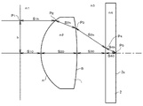
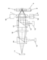
いま、図1において、対物レンズ1を用いて基板2の情報記録面2aにレーザビームを集光させる場合について説明する。ここで、対物レンズ1の面Aは光入射側面、面Bは光出射側面であり、基板2の情報記録面2aは対物レンズ1側とは反対側にある。
Now, a case where a laser beam is focused on the
図1に、対物レンズ1の光路が模式的に示されている。図1において、対物レンズ1に入射するレーザビームは平行光とする。従って、図1に示された光学系は、いわゆる無限光学系である。さらに、図1には、対物レンズ1の光軸OAからこれに垂直な方向の距離(光線高さ)hの位置P1を通る光線が、光軸OAを横切る点(集光点)P5に達するまでの光路が模式的に示されている。
FIG. 1 schematically shows the optical path of the
ここで、かかる光路での対物レンズ1への入射点をP2、対物レンズ1からの出射点をP3、透明基板2への入射点をP4とし、各点間の空間距離、屈折率を、
点P1〜入射点P2:空間距離=S1h,屈折率=n1、
入射点P2〜出射点P3:空間距離=S2h,屈折率=n2、
出射点P3〜入射点P4:空間距離=S3h,屈折率=n3、
入射点P4〜集光点P5:空間距離=S4h,屈折率=n4
とする。
このとき、点P1から集光点P5までの光路長Lhは、
Lh=n1×S1h+n2×S2h+n3×S3h+n4×S4h ・・・・(3)
で表わされる。なお、光軸OA上での光路長Lhは、この式(3)において、h=0の場合である。
Here, the incident point to the
Point P 1 to incident point P 2 : spatial distance = S 1h , refractive index = n 1 ,
Entrance point P 2 to exit point P 3 : spatial distance = S 2h , refractive index = n 2 ,
Outgoing point P 3 to incident point P 4 : spatial distance = S 3h , refractive index = n 3 ,
Incident point P 4 ~ focal point P 5: CLEARANCE = S 4h, refractive index = n 4
And
At this time, the optical path length L h from the point P 1 to the condensing point P 5 is
L h = n 1 × S 1h + n 2 × S 2h + n 3 × S 3h + n 4 × S 4h (3)
It is represented by The optical path length L h on the optical axis OA is a case where h = 0 in the equation (3).
この式(3)は、任意の光線高さhについて該当するものであり、収差補正されている場合には、任意の夫々の光線高さhに対する集光点P5が夫々の許容範囲内で情報記録面2a上にある。すなわち、本発明は、例えば厚さが異なる複数の基板夫々毎に異なる波長のレーザビームを用いることにより、色収差と球面収差とが相殺し合って任意の光線高さhに対する集光点P5が夫々の許容範囲内で情報記録面2a上にあるようにするものである。
The equation (3) is intended as applicable for any ray height h, when it is the aberration correction, the focal point P 5 is within the allowable range of each relative to a light ray with a height h of people any husband It is on the
また、平行光入射、いわゆる無限系について説明したが、対物レンズ1への入射光は発散光、すなわち、有限系としてもよい。またさらに、異なる光記録媒体、波長ごとに無限系と有限系を使い分けてもよい。あるいはまた、異なる光記録媒体ごとに同じ有限系でも入射する光線の発散度合いを変えるようにしてもよい。また、対物レンズへの入射光は収束光としてもよい。
Moreover, although the parallel light incidence, so-called infinite system has been described, the incident light to the
例えば、HDDVD(AOD)における405nmの単色光(λ1)と、DVDにおける655nmの単色光(λ2)と、CDにおける790nmの単色光(λ3)とが用いられたとする。このような場合に、これらの波長が共通して使用される領域を複数の非球面部に分割したレンズ面とすることができる。この手法では、その任意の非球面部の光路長が、他の非球面部の光路長と当該各単色光の波長λiのほぼ整数倍だけ異なり、なおかつ、この各非球面部における各単色光の波面収差の最大値と最小値の差を△Vd(λ1)と△Vd(λ2)(dは1,2・・・・の整数で各非球面部を意味する)とする。 For example, assume that 405 nm monochromatic light (λ 1 ) in HDDVD (AOD), 655 nm monochromatic light (λ 2 ) in DVD, and 790 nm monochromatic light (λ 3 ) in CD are used. In such a case, a lens surface in which these wavelengths are used in common can be divided into a plurality of aspherical surfaces. In this method, the optical path length of the arbitrary aspheric surface portion differs from the optical path length of the other aspheric surface portions by almost an integral multiple of the wavelength λ i of each monochromatic light, and each monochromatic light in each aspheric surface portion is different. Let ΔVd (λ 1 ) and ΔVd (λ 2 ) (d is an integer of 1, 2,..., Meaning each aspherical portion).
このときに、いずれの非球面部においても、各単色光の波面収差の最大値と最小値の差の比を0.4以上2.5以下、好ましくは0.5以上2.0以下とすることにより、全ての波長においてレンズ全体として許容範囲のRMS(Root Mean Square)波面収差を確保することができる。また更に、CDでのRMS波面収差値を良くするには、入射光線を発散光とするか、HDDVDやDVDに比べて発散度合いの強い入射光線とするように設定すればよい。これによって、基板厚が厚くなることによる球面収差と入射光線の発散度合いが強くなることによる球面収差とが相殺しあって、CDで発生している球面収差を補正することが可能である。 At this time, the ratio of the difference between the maximum value and the minimum value of the wavefront aberration of each monochromatic light is 0.4 or more and 2.5 or less, preferably 0.5 or more and 2.0 or less, in any aspheric part. As a result, RMS (Root Mean Square) wavefront aberration within an allowable range can be ensured for the entire lens at all wavelengths. Furthermore, in order to improve the RMS wavefront aberration value for a CD, the incident light beam may be set to be diverging light or set to be an incident light beam having a higher degree of divergence than HDDVD or DVD. Thereby, the spherical aberration due to the increase in the substrate thickness and the spherical aberration due to the increase in the degree of divergence of incident light cancel each other, and the spherical aberration occurring in the CD can be corrected.
なお、ここでいう波面収差は光線高さ(h)をh=0の場合の光路長をL0とし、各光線高さにおける光路長をLhとすると、波面収差Vhは、下記の式(4)で表される。
Vh=(Lh−L0)/λi ・・・・・・・・・・・・・・・・・・(4)
Incidentally, the wavefront aberration ray height here a (h) and the optical path length in the case of h = 0 and L 0, when the optical path length of each ray height and L h, wavefront aberration V h is the following formula It is represented by (4).
V h = (L h −L 0 ) / λ i (4)
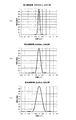
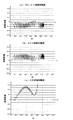
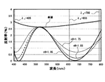
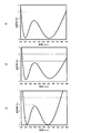
図2に、HDDVDとDVDとCDの波面収差が対比して示されている。この図2において、横軸は光線高さ、縦軸は波面収差である。図2(a)はHDDVDの各非球面部の波面収差を、図2(b)はDVDの各非球面部の波面収差を、図2(c)はCDの各非球面部の上記式で求められる波面収差を表している。 In FIG. 2, the wavefront aberrations of HDDVD, DVD, and CD are shown in contrast. In FIG. 2, the horizontal axis represents the light ray height, and the vertical axis represents the wavefront aberration. 2A shows the wavefront aberration of each aspheric part of the HDDVD, FIG. 2B shows the wavefront aberration of each aspheric part of the DVD, and FIG. 2C shows the above formula of each aspheric part of the CD. It shows the required wavefront aberration.
例えば、非球面部の第1領域におけるその非球面部内の波面収差の最大値と最小値の差は、△V1(λ1)、△V1(λ2)で定義される。本発明では、後に説明する発明の実施の形態で明らかにされるように、いずれの非球面部においても各波長の波面収差の最大値と最小値の差の比は0.4以上2.5以下である。すなわち、本発明は、いずれの波長においても各非球面部で波面収差に一定の分布を有する。本発明は、この点でも、従来の一方の波長を基準にレンズ面を構成し、他方の波長においてのみ位相ずれを利用して波面収差を補正する方式と異なる。 For example, the difference between the maximum value and the minimum value of the wavefront aberration in the aspherical portion in the first region of the aspherical portion is defined by ΔV 1 (λ 1 ) and ΔV 1 (λ 2 ). In the present invention, as will be clarified in the embodiments of the invention described later, the ratio of the difference between the maximum value and the minimum value of the wavefront aberration at each wavelength is 0.4 or more and 2.5 in any aspherical portion. It is as follows. That is, the present invention has a constant distribution of wavefront aberration at each aspherical portion at any wavelength. The present invention is also different from the conventional method in which the lens surface is configured based on one of the wavelengths and the wavefront aberration is corrected using the phase shift only at the other wavelength.
また、本発明の多波長用レンズでは、いずれの非球面部の各領域においても、各波長の波面収差の最大値と最小値の差を、0.14λi以下、好ましくは、0.12λi以下、さらに好ましくは0.10λi以下とすることができる。例えば、これら最大値と最小値の差が0.14λi以下である場合の一例として、波長が790nmである場合には110.6nm以下、波長が655nmである場合には91.7nm以下、波長が405nmである場合は56.7nm以下とすることができる。これにより、本発明の多波長用レンズは、各波長においてさらに良好な光学特性を確保することができる。 Further, in multi-wavelength lens of the present invention, even in the region of one of the non-spherical surface portion, the difference between the maximum value and the minimum value of the wavefront aberration of each wavelength, 0.14Ramuda i or less, preferably, 0.12Ramuda i Hereinafter, it is more preferably 0.10λ i or less. For example, as an example when the difference between the maximum value and the minimum value is 0.14λ i or less, when the wavelength is 790 nm, it is 110.6 nm or less, and when the wavelength is 655 nm, the wavelength is 91.7 nm or less. Can be set to 56.7 nm or less. Thereby, the multi-wavelength lens of the present invention can secure even better optical characteristics at each wavelength.
さらに、本発明では、二波長用光学系の場合、各波長の波面収差をそれらがほぼ対称形となる多波長用レンズを用いることにより、二波長のバランスが取れ、さらにRMS波面収差を低減することができる。
この結果、RMS波面収差は、HDDVDでは0.03152λ1RMS、DVDでは0.03237λ2RMSとなり、HDDVDのRMS波面収差もDVDのRMD波面収差もほぼ等しい値となっている。なお、CDのRMS波面収差については0.01764λ3RMSと、HDDVDやDVDに比べると小さい値となっている。
Furthermore, in the present invention, in the case of a two-wavelength optical system, by using a multi-wavelength lens in which the wavefront aberrations of the respective wavelengths are almost symmetrical, the two wavelengths are balanced, and the RMS wavefront aberration is further reduced. be able to.
As a result, the RMS wavefront aberration is 0.03152λ 1 RMS for HDDVD and 0.03237λ 2 RMS for DVD, and the RMS wavefront aberration of HDDVD and the RMD wavefront aberration of DVD are almost equal. Note that the RMS wavefront aberration of the CD is 0.01764λ 3 RMS, which is smaller than that of HDDVD or DVD.
790nmのCDの記録再生については、対物レンズへ入射する入射光の発散度合い、幾何光学的な意味でのいわゆる対物レンズにとっての物体距離を変えることができる。これは、入射光線の発散度合いが異なることによって発生する球面収差が変化するので、球面収差の補正手段としては有効である。このことは、以下に発明の実施の形態で説明されている。 For recording and reproduction of a 790 nm CD, the degree of divergence of incident light incident on the objective lens and the object distance for the so-called objective lens in terms of geometric optics can be changed. This is effective as a means for correcting spherical aberration because the spherical aberration that occurs due to the degree of divergence of incident light varies. This is described below in the embodiments of the invention.
また、以下に説明する本発明の実施の形態では、波長405nmと655nmの入射光線を無限系とし、波長790nmの入射光線を有限系としている。すなわち、波長405nmと655nmの入射光線の発散度合いを同じにし、波長790nmの入射光線の発散度合いを変えている。ここで、使用波長や基板厚みによって、どの波長の入射光線の発散度合いを変えるか、または変えずに同じにしておくかは、その都度、収差が低減するように決めることができる。また、全ての波長の光線を発散光線で入射させてもよいし、逆に収束光線で入射させてもよい。 In the embodiment of the present invention described below, incident light beams with wavelengths of 405 nm and 655 nm are infinite systems, and incident light beams with wavelengths of 790 nm are finite systems. That is, the divergence degree of incident light with a wavelength of 405 nm is made the same as the divergence degree of incident light with a wavelength of 790 nm. Here, depending on the wavelength used and the thickness of the substrate, it is possible to determine which wavelength of incident light divergence is to be changed or not to be changed so as to reduce aberration each time. Further, light beams of all wavelengths may be incident as divergent light beams, or conversely, they may be incident as convergent light beams.
以下に説明する本発明の実施の形態により、例えば基板の厚さが異なるいずれの光ディスクに対しても、情報記録面に良好な光スポットを形成することが可能となる。なお、このことは、ディスク基板の厚みが異なっていなくても、つまり、厚みが同じで波長が異なるような場合であっても、図1に示す集光点P5を夫々の許容範囲内にすることにより適用可能である。また、本発明は、光記録媒体に限らず、光通信などで異なる波長のレーザビームを同一のレンズもしくは光学系を通過させるような場合にも適用可能である。 The embodiment of the present invention described below makes it possible to form a good light spot on the information recording surface, for example, for any optical disk having a different substrate thickness. Note that the same is not different in thickness of the disc substrate, that is, even if the thickness is different, such as the same wavelength, within the allowable range of people each converging point P 5 shown in FIG. 1 This is applicable. The present invention is not limited to an optical recording medium, and can also be applied to cases where laser beams having different wavelengths are allowed to pass through the same lens or optical system in optical communication or the like.
以下、本発明を実施するための最良の形態について具体的に説明する。
発明の実施の形態1.
発明の実施の形態1(第1の実施形態)では、3種類の光ディスク、即ち、HDDVD(λ1=405nm)とDVD(λ2=655nm)とCD(λ3=790nm)とを例に、図面を用いて説明する。第1の実施形態におけるレンズは、プラスチック樹脂相当の屈折率のものであるが、レンズ材質をガラスとしたい場合にはガラスの屈折率で設計すればよい。
The best mode for carrying out the present invention will be specifically described below.
In the first embodiment of the invention (first embodiment), three types of optical disks, ie, HDDVD (λ 1 = 405 nm), DVD (λ 2 = 655 nm), and CD (λ 3 = 790 nm) are taken as examples. This will be described with reference to the drawings. The lens in the first embodiment has a refractive index equivalent to that of a plastic resin. However, if the lens material is glass, it may be designed with the refractive index of glass.
図3は、本発明に係る対物レンズの作用の一例を示す模式図であり、図3(a)はHDDVDに対するもの、図3(b)はDVDに対するもの、図3(c)はCDに対するものである。図3において、1は第1の実施形態における対物レンズ、2はHDDVDの透明基板、3はDVDの透明基板、4はCDの透明基板、5は絞り、6は波長選択性絞りである。 FIG. 3 is a schematic diagram showing an example of the action of the objective lens according to the present invention. FIG. 3 (a) is for HDDVD, FIG. 3 (b) is for DVD, and FIG. 3 (c) is for CD. It is. In FIG. 3, 1 is the objective lens in the first embodiment, 2 is an HDDVD transparent substrate, 3 is a DVD transparent substrate, 4 is a CD transparent substrate, 5 is a stop, and 6 is a wavelength selective stop.
まず、図3(a)において、対物レンズ1は、図示しない光ディスク装置の光ヘッドに設けられ、HDDVDが、この光ディスク装置に装着されている。平行光として入射されるレーザビームは、この対物レンズ1によって集光され、これにより、記録再生が行なわれる。ここで、HDDVD基板2の厚さt1は0.6mmであり、このときのレーザビーム5は、波長λ1=405nmのレーザビームが開口数NA=0.650の光束として用いられる。かかる条件のもとに、このようなレーザビームは、HDDVD基板2の対物レンズ1側とは反対側の面の情報記録面2aに集光される。
First, in FIG. 3A, the
図3(b)は、上記と同じ図示しない光ディスク装置にDVDが装着され、同じ対物レンズ1を用いて記録再生が行なわれる場合を示している。ここで、DVD基板3の厚さt2は0.6mmであり、このときのレーザビーム5は、波長λ2=655nmのレーザビームが開口数NA=0.628の光束として用いられる。なお、HDDVDとDVDにおいて、絞り5の直径がHDDVDとDVDで同じなのに、NAが0.650と0.628と異なっている。これは、波長が405nmと655nmと異なっているために、対物レンズ1の屈折率が異なり、それにより焦点距離がそれぞれ違うからである。
FIG. 3B shows a case where a DVD is mounted on the same optical disk device (not shown) as described above, and recording / reproduction is performed using the same
図3(c)は、上記と同じ図示しない光ディスク装置にCDが装着され、同じ対物レンズ1を用いて記録再生が行なわれる場合を示している。ここで、CD基板4の厚さt3は1.2mmであり、このときのレーザビームは、波長λ3=790nmのレーザビームが発散光の状態で対物レンズ1に入射し、ほぼ開口数NA=0.470の光束として用いられる。
FIG. 3C shows a case where a CD is mounted on the same optical disk apparatus (not shown) as described above, and recording / reproduction is performed using the same
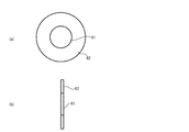
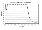
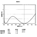
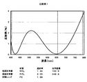
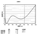
なお、図3(a)(b)(c)に示している波長選択性フィルター6については、図4に示すように、内側の全光透過領域と外側のCD(790nm)光遮断領域とに区分けされている。具体的には、内側にマスクをして750nm以上の光を反射するようなダイクロイックコーティングを施せばよい。
As shown in FIG. 4, the wavelength
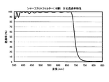
より具体的には、例えば、図5に示すような分光透過率特性を示すダイクロイックコートをCD光遮断領域に施せばよい。これによって、例えば、外側のCD光遮断領域については、図5に示す分光透過率特性を有する波長選択性フィルター6を得ることができる。これによって、外側領域においてCD光のみを遮断し、DVDとHDDVD光は透過する、という目的を達成することができる。その結果、HDDVDのNA(開口数)は0.650、DVDのNAは0.628、CDのNAは0.470とすることができる。
More specifically, for example, a dichroic coat exhibiting spectral transmittance characteristics as shown in FIG. 5 may be applied to the CD light blocking region. Thereby, for example, the wavelength
また、図5に示す分光透過率特性は、波長750nm以下において100%の透過率になり、波長750nm以上において0%の透過率になるという理想状態に対して、99%と0.2%と、理想状態に近いものである。これが現実のフィルター特性で実現不可能であるならば、例えば、波長700nm以下での透過率が90%以上で、波長770nm以上で透過率が5%以下程度のものとすることができる。この場合でも、光ディスク装置の信号レベルがやや下がるとか、CDジッター特性が若干劣化するという副作用は発生するが、使用不可能というレベルではなく、使用可能である。 The spectral transmittance characteristics shown in FIG. 5 are 99% and 0.2% with respect to the ideal state where the transmittance is 100% at a wavelength of 750 nm or less and 0% at a wavelength of 750 nm or more. It is close to the ideal state. If this cannot be realized with actual filter characteristics, for example, the transmittance at a wavelength of 700 nm or less is 90% or more, and the transmittance is about 5% or less at a wavelength of 770 nm or more. Even in this case, there is a side effect that the signal level of the optical disk device is slightly lowered or the CD jitter characteristic is slightly deteriorated, but it is not at a level where it cannot be used but can be used.
このような第1の実施形態では、HDDVD、DVD,CDの両方共に、任意の光線高さhに対して上記した式(3)で示す光路長Lhが収差を低減して許容値内とするような値とするように、対物レンズ1のレンズ面形状が設定されている。これによって、HDDVD、DVD,CDともに、収差が良好に低減されて、それぞれの情報記録面上で良好な光スポットを得ることができる。
In such a first embodiment, the optical path length L h shown in the above equation (3) is within the allowable value by reducing the aberration with respect to an arbitrary light beam height h in both of the HDDVD, DVD, and CD. The lens surface shape of the
第1の実施形態では、光入射面Aを光軸から半径方向に複数の区間に区分し、夫々の区間の面形状を、HDDVD、DVD、CDともに収差が許容値内に良好に低減されるように設定している。 In the first embodiment, the light incident surface A is divided into a plurality of sections in the radial direction from the optical axis, and the aberration of each section of the HDDVD, DVD, and CD is satisfactorily reduced within an allowable value. It is set as follows.
図6を用いて、第1の実施形態における光入射面Aの面形状について説明する。いま、この光入射面Aの光線高さh方向(半径方向)の光軸OA側からj番目の区間での点a,b間の距離を次の関数ZAj、即ち、

図6において、対物レンズ1の光出射側面Bについて、光線高さhの点をc、この点cから光軸OAに平行な方向での光出射側面B上の点をdとする。このとき、この光出射側面Bの面形状は、任意の光線高さhに対する点c,d間の距離ZBにより、次式で表わされるように設定する。
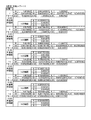
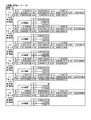
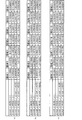
そして、HDDVD、DVD、CDともに、収差を許容値内に良好に低減するための式(5)での区間毎に、その範囲(hの範囲)とその各定数B,C,K,A4,A6,A8,A10,A12,A14,A16の値を算出する。この算出結果が図7の表に示されている。さらに、式(6)の各係数の値についても算出し、この算出結果が、図8の表に示されている。 For each of HDDVD, DVD, and CD, the range (range of h) and its constants B, C, K, and A 4 for each section in Equation (5) for satisfactorily reducing the aberration within an allowable value. , A 6 , A 8 , A 10 , A 12 , A 14 , A 16 are calculated. The calculation results are shown in the table of FIG. Further, the value of each coefficient in the equation (6) is also calculated, and the calculation result is shown in the table of FIG.
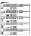
また、図9の表に、HDDVD、DVD、CDにおいて対物レンズを基準とした図3に相当する光学系における、各光学要素間の距離、配置が示さている。 Further, the table of FIG. 9 shows the distance and arrangement between the optical elements in the optical system corresponding to FIG. 3 with respect to the objective lens in HDDVD, DVD, and CD.
対物レンズ1の光軸上の面頂点f,e間の距離、即ち、中心厚さt0は1.94mmである。さらに、波長λ1=405nm(ブルーレイディスク)での屈折率nは1.54972、波長λ2=655nm(DVD)での屈折率nは1.53、波長λ3=790nm(CD)での屈折率nは1.5263653である。
The distance between the surface vertices f and e on the optical axis of the
透明基板の厚さと屈折率は、波長λ1=405nm(ブルーレイディスク)では厚み0.6mmで屈折率は1.6235、波長λ2=655nm(DVD)では厚み0.6mmで屈折率は1.58であり、波長λ3=790nm(CD)では厚み1.2mmで屈折率は1.57163である。 The thickness and refractive index of the transparent substrate are 0.6 mm and 1.6235 for the wavelength λ 1 = 405 nm (Blu-ray disc), and 0.6 mm and the refractive index is 1.5 for the wavelength λ 2 = 655 nm (DVD). 58, and the wavelength λ 3 = 790 nm (CD) has a thickness of 1.2 mm and a refractive index of 1.57163.
また、波長405nmのHDDVDの場合、NAは0.650、焦点距離は3.1015mmであり、波長655nmのDVDの場合、NAは0.628で、焦点距離は3.2116mmである。入射平行光束有効直径は、HDDVDでもDVDでもφ4.032である。また、φ4.032のA面側レンズ全面が、HDDVD/DVD共通使用領域である。波長790nmのCDの場合、NAは0.470で、焦点距離は3.2327mmである。 In the case of HDDVD having a wavelength of 405 nm, NA is 0.650 and the focal length is 3.1015 mm. In the case of DVD having a wavelength of 655 nm, NA is 0.628 and the focal length is 3.2116 mm. The effective diameter of the incident parallel light beam is φ4.032 for both HDDVD and DVD. Further, the entire surface of the A-side lens with φ4.032 is the HDDVD / DVD common use area. For a CD with a wavelength of 790 nm, the NA is 0.470 and the focal length is 3.2327 mm.
図9は、絞り、対物レンズ、ディスクについて、また対物レンズにとっての物体面を表している。図9に示すように、例えば、HDDVDやDVDでは、対物レンズへの入射光は平行光、つまり対物レンズにとっての物体面と対物レンズとの距離は∞となっている。現実の光学系の場合には、コリメータレンズの焦点位置にHDDVDレーザー、DVDレーザーを配置してコリメータレンズ出射光を平行光として対物レンズに入射させる。 FIG. 9 shows the object plane for the stop, objective lens, disk and for the objective lens. As shown in FIG. 9, for example, in HDDVD and DVD, the incident light to the objective lens is parallel light, that is, the distance between the object plane for the objective lens and the objective lens is ∞. In the case of an actual optical system, an HDDVD laser and a DVD laser are arranged at the focal position of the collimator lens, and collimator lens emission light is incident on the objective lens as parallel light.
CDの場合には、物体面から対物レンズまでの距離は49.4mmであり、発散光を対物レンズに入射させる。このCDについても、現実の光学系の場合には、CDレーザーの発光点から対物レンズの光源側の面頂点までの距離を49.4mmとしてもよい。この場合には、光ピックアップが大型化してしまうことが懸念される。 In the case of CD, the distance from the object surface to the objective lens is 49.4 mm, and divergent light is incident on the objective lens. Also for this CD, in the case of an actual optical system, the distance from the light emitting point of the CD laser to the surface vertex on the light source side of the objective lens may be 49.4 mm. In this case, there is a concern that the optical pickup becomes large.
このような場合には、コリメータレンズをCDレーザー光源と対物レンズとの間に配置し、CDレーザーの発光点の位置をコリメータレンズの焦点位置よりもコリメータレンズに近いところに配置すればよい。これによって、CDレーザーを発してコリメータレンズを通過した光は発散光となり、対物レンズに入射する。その際、対物レンズへの入射光が、コリメータレンズ無しの状態で49.4mmの距離から発せられた光線入射状態と同じになるように、コリメータレンズとCDレーザーを配置すればよい。 In such a case, the collimator lens may be disposed between the CD laser light source and the objective lens, and the position of the light emission point of the CD laser may be disposed closer to the collimator lens than the focal position of the collimator lens. As a result, the light emitted from the CD laser and passed through the collimator lens becomes divergent light and enters the objective lens. At this time, the collimator lens and the CD laser may be arranged so that the incident light to the objective lens is the same as the light incident state emitted from a distance of 49.4 mm without the collimator lens.
また図9に、絞り面の有効直径が示されているが、上記の図4に示されるような波長選択性フィルターを用いている。すなわち、図4において、全光透過領域の外径=CD光遮断領域の内径をφ3.15とし、CD光遮断領域の外径をHDDVDやDVDの有効直径以上のφ4.032以上としている。具体的には、絞り面の有効直径を、鏡枠による保持に必要な寸法も考慮して、例えばφ4.8にしている。 FIG. 9 shows the effective diameter of the diaphragm surface, and a wavelength selective filter as shown in FIG. 4 is used. That is, in FIG. 4, the outer diameter of the total light transmission region = the inner diameter of the CD light blocking region is set to φ3.15, and the outer diameter of the CD light blocking region is set to φ4.032 or more which is larger than the effective diameter of HDDVD or DVD. Specifically, the effective diameter of the diaphragm surface is set to φ4.8, for example, in consideration of the dimensions necessary for holding by the lens frame.
波長選択性フィルターの厚みについては、入射光線が0度入射することが基本である。この入射光線は、レーザーや各種ミラーなどの部品取り付け位置、精度のバラツキや、2波長レーザーや3波長レーザーによる発光点の光軸直角方向の位置ズレなども考慮すると、斜入射になることもある。それ故、波長選択性フィルターの厚みは、薄い方が望ましいが、第1の実施形態では0.5mmとしている。 Regarding the thickness of the wavelength selective filter, it is fundamental that incident light is incident at 0 degree. This incident light beam may be obliquely incident in consideration of the mounting position of parts such as lasers and various mirrors, the variation in accuracy, and the positional deviation in the direction perpendicular to the optical axis of the emission point by the two-wavelength laser or the three-wavelength laser. . Therefore, the thickness of the wavelength selective filter is desirably thin, but is 0.5 mm in the first embodiment.
図9に示された第1の実施形態について、式(1)、(2)に示すS1、S2、S3の関係について見てみると、
HDDVD;λ1=405nm,S1=∞、
DVD ;λ2=655nm,S2=∞、
CD ;λ3=790nm,S3=49.4mm
であるから、
405nm(λ1)<790nm(λ3)
であり、
(1/S1)=(1/∞)=0、
(1/S3)=(1/49.4)=0.0202429
であるから、
0<0.0202429、すなわち(1/S1)<(1/S3)
となる。
つまりHDDVDとCDにおいて、
λ1<λ3、かつ、(1/S1)<(1/S3)
が成立している。
Regarding the first embodiment shown in FIG. 9, when looking at the relationship between S 1 , S 2 , and S 3 shown in equations (1) and (2),
HDDVD; λ 1 = 405 nm, S 1 = ∞,
DVD; λ 2 = 655 nm, S 2 = ∞,
CD: λ 3 = 790 nm, S 3 = 49.4 mm
Because
405 nm (λ 1 ) <790 nm (λ 3 )
And
(1 / S 1 ) = (1 / ∞) = 0,
(1 / S 3 ) = (1 / 49.4) = 0.0202429
Because
0 <0.0202429, ie (1 / S 1 ) <(1 / S 3 )
It becomes.
In other words, in HDDVD and CD,
λ 1 <λ 3 and (1 / S 1 ) <(1 / S 3 )
Is established.
また、
655nm(λ2)<790nm(λ3)
であり、
(1/S2)=(1/∞)=0、
(1/S3)=(1/49.4)=0.0202429
であるから、
0<0.0202429、すなわち(1/S2)<(1/S3)
となる。
つまり、DVDとCDにおいて、
λ2<λ3 かつ (1/S2)<(1/S3)
が成立している。
Also,
655 nm (λ 2 ) <790 nm (λ 3 )
And
(1 / S 2 ) = (1 / ∞) = 0,
(1 / S 3 ) = (1 / 49.4) = 0.0202429
Because
0 <0.0202429, ie (1 / S 2 ) <(1 / S 3 )
It becomes.
In other words, in DVD and CD,
λ 2 <λ 3 and (1 / S 2 ) <(1 / S 3 )
Is established.
ちなみに、上記対物レンズの屈折率は、プラスチック樹脂の屈折率に近い値である。例えば、ポリオレフィン樹脂やアクリル系の樹脂などを適用する場合には、その樹脂の屈折率の値を用いて対物レンズを設計して各非球面形状やレンズの中心厚を設定すればよい。特に、ポリオレフィン系樹脂は高湿環境においても水をほとんど吸わないことから、屈折率の変化がない点で有利である。アクリル系樹脂はブルーレイの透過率が良い点や、ブルーレイ(405nm)付近の透過率の経時変化が少ない点などで有利である。 Incidentally, the refractive index of the objective lens is close to the refractive index of the plastic resin. For example, when a polyolefin resin, an acrylic resin, or the like is applied, an objective lens may be designed using the refractive index value of the resin to set each aspheric shape and the center thickness of the lens. In particular, polyolefin resins are advantageous in that they do not absorb water even in a high humidity environment, and therefore there is no change in refractive index. The acrylic resin is advantageous in that the transmittance of Blu-ray is good and the change with time of the transmittance in the vicinity of Blu-ray (405 nm) is small.
また、対物レンズの材料としては、複屈折が少ない材料を選んだ方が、射出成形や注型等でレンズを製作した際に波面収差として良い値を得やすいので有利である。さらに、上記のようにアクリル系材料を使用する際には、高湿環境下での吸水率の変化が問題となる場合がある。従って、アクリル系材料を使用する場合には、予め調湿を行ってある程度吸水させておくことが、その後の絶乾に近い環境下や高湿に近い環境下に置かれる場合などを考慮すると有効である。その場合には、調湿を行った後の、ある程度吸水した状態での樹脂の屈折率の値を用いて設計すればよい。 Further, it is advantageous to select a material with low birefringence as the material of the objective lens, since it is easy to obtain a good value as wavefront aberration when a lens is manufactured by injection molding or casting. Furthermore, when an acrylic material is used as described above, a change in water absorption rate under a high humidity environment may be a problem. Therefore, when using acrylic materials, it is effective to adjust the humidity in advance and absorb water to some extent, considering the case where it is placed in an environment close to absolutely dry or in an environment close to high humidity. It is. In that case, the design may be performed using the value of the refractive index of the resin in a state where water has been absorbed to some extent after humidity control.
なお、式(6)において、上記係数C,K,A4,A6,A8,A10の値を代入して任意の光線高さh(≠0)に対する距離ZBを求めると、その値は負の値となる。これは光出射側面B上の点dが点c、従って、この光出射側面Bの光軸OAが通る面頂点eよりも出射面側(図6での左側)に位置することを示している。逆に、距離ZBが正の値である場合には、逆の右側に位置することを示している。 In the equation (6), when the values of the coefficients C, K, A 4 , A 6 , A 8 , A 10 are substituted to obtain the distance Z B for an arbitrary ray height h (≠ 0), The value is negative. This indicates that the point d on the light emission side surface B is located at the point c, and therefore is located on the emission surface side (left side in FIG. 6) from the surface vertex e through which the optical axis OA of the light emission side surface B passes. . On the other hand, when the distance Z B is a positive value, it indicates that the distance is on the right side.
(i)ここで、収差を評価するための上記の収差の許容値としては、対物レンズ1への入射レーザビームが入射角0゜である場合(即ち、光軸OAに平行な平行光)について、HDDVD(波長λ1=405nm),DVD(波長λ2=655nm),CD(波長λ3=790nm)ともに、RMS波面収差で0.035λ、好ましくは、0.033λ、とする。第1の実施形態では、HDDVD,DVD,CDの波面収差がかかる許容値以下となるように、光出射面Bと光入射面Aとが上記の面形状に設定されている。
(I) Here, as an allowable value of the aberration for evaluating the aberration, the incident laser beam to the
第1の実施形態では、3種類の異なる波長λ1,λ2、λ3を用いた場合を示しているが、一般に、n種類(但し、nは2以上の整数)の異なる波長λi(但し、i=1,2,・・・,n)を用いる場合も、同様である。 In the first embodiment, a case where three different wavelengths λ 1 , λ 2, and λ 3 are used is shown, but in general, n types (where n is an integer of 2 or more) different wavelengths λ i (where n is an integer of 2 or more). However, the same applies to the case of using i = 1, 2,..., N).
(ii)また、このようにn種類の波長λiを用いた場合について、これら波長λiの入射レーザビームが入射角0゜である場合の夫々のRMS波面収差をWi・λiとすると、これら収差は、
ただし、式(7)において、i番目の該光ビームの波長をλi(i=1,2,・・・)、全ての波長にわたる個々のRMS波面収差の二乗の総和をΣWi 2、波長λiの光ビームのRMS波面収差をWi・λiとする。 However, in equation (7), the wavelength of the i-th light beam is λ i (i = 1, 2,...), The sum of the squares of individual RMS wavefront aberrations over all wavelengths is ΣW i 2 , the wavelength the RMS wavefront aberration of the light beam of λ i and W i · λ i.
(iii)あるいはまた、異なるn種類の波長λiのレーザビームを用いる場合、夫々の波長λiのうちで最大のRMS波面収差をWmax、最小のRMS波面収差をWminとすると、
1≦Wmax/Wmin<Wth
とする。この場合の許容値Wthとしては、1.8、好ましくは1.6、さらに好ましくは1.4とする。第1の実施形態の場合には、DVDのRMS波面収差W1とCDのRMS波面収差W2とのいずれか一方が最大のRMS波面収差Wmaxとなり、他方が最小のRMS波面収差Wminとする。
(iii) Alternatively, when using a laser beam of different n types of wavelengths lambda i, and the maximum of the RMS wavefront aberration among the wavelengths of respective lambda i W max, the minimum RMS wavefront aberration and W min,
1 ≦ W max / W min <W th
And In this case, the allowable value Wth is 1.8, preferably 1.6, and more preferably 1.4. In the case of the first embodiment, the RMS wavefront aberration W min of either the maximum RMS wavefront aberration W max, and the other is a minimum with the RMS wavefront aberration W 2 of RMS wavefront aberration W 1 and CD of DVD To do.
図2に、第1の実施形態の波面収差図が示されている。HDDVDのRMS波面収差が0.03152λRMSであり、DVDのRMS波面収差が0.03237λRMS、CDのRMS波面収差が0.01764λRMSである。これらHDDVDもDVDもCDも0.035λRMS以下、さらに0.033λRMS以下となっている。
式(7)の値については、
For the value of equation (7),
また、図10に、第1の実施形態の光スポット図が示されている。1/e2(=0.135)の相対光強度となる光スポット直径は、405nmのHDDVDのときで0.5149μm、655nmのDVDで0.8606μm、790nmのCDで1.3979μmとなっている。 FIG. 10 shows a light spot diagram of the first embodiment. The light spot diameter at 1 / e 2 (= 0.135) relative light intensity is 0.5149 μm for 405 nm HDDVD , 0.8606 μm for 655 nm DVD, and 1.3979 μm for 790 nm CD. .
なお、上記の光SPOT径は、無収差の理想的な光学系においては、ほぼ0.82×波長/NAとなり、現実のレンズでは、一般的には小さい方が望ましい。また、この光SPOT径が、小さすぎても他の副作用が考えられるので、0.82×波長/NAの値の0.9倍〜1.03倍位の値となっていることが望ましい。またさらに、光SPOT径が小さすぎると、超解像などの副作用が出ているおそれがあり、大きすぎると光SPOTの集光特性が悪いことになり、結局絞れていないことになり、ジッター特性などへの悪影響が考えられる。 Note that the above optical spot diameter is approximately 0.82 × wavelength / NA in an ideal optical system having no aberration, and it is generally desirable for an actual lens to be small. In addition, even if the optical SPOT diameter is too small, other side effects can be considered. Therefore, it is desirable that the value is 0.9 times to 1.03 times the value of 0.82 × wavelength / NA. Furthermore, if the optical spot diameter is too small, side effects such as super-resolution may occur. If the optical spot diameter is too large, the light SPOT condensing characteristic will be poor, and the optical spot will not be narrowed down. Adverse effects on the
ちなみに、第1の実施形態について評価すると、次のようになる。
HDDVD(波長405nm、NA0.650)では、0.82×波長/NA=0.5109μmである。現実のSPOT径は、0.5149μmなので、0.82×波長/NAによるSPOT径の1.0078倍であり、0.9〜1.02倍の間に入っている。
DVD(波長655nm、NA0.628)では、0.82×波長/NA=0.8553μmである。現実のSPOT径は、0.8606μmなので、0.82×波長/NAによるSPOT径の1.0062倍で、0.9〜1.02倍の間に入っている。
CD(波長790nm、NA0.470)では、0.82×波長/NA=1.3783μmである。現実のSPOT径は、1.3979μmなので、0.82×波長/NAによるSPOT径の1.0142倍で、0.9〜1.02倍の間に入っている。
Incidentally, the evaluation of the first embodiment is as follows.
In HDDVD (
In DVD (
For CD (
また、このレンズでは、波面収差がDVD655nmの波長において+側に、HDDVD405nmの波長において−側に現れるように設定され、両波面収差がほぼ対称形となる。
なお、光軸を中心に分割された隣接する各非球面部で光路長の差が生じているが、その差はDVDとCD波長に対応してほぼ整数倍に、HDDVD(ブルーレイ、405nm)波長に対応してほぼ整数の2倍になるように設計されている。
In this lens, the wavefront aberration is set so as to appear on the + side at the wavelength of DVD655 nm and on the-side at the wavelength of HDDVD405 nm, and both wavefront aberrations are substantially symmetrical.
Note that there is a difference in optical path length between adjacent aspherical surfaces divided about the optical axis, and the difference is approximately an integer multiple corresponding to the DVD and CD wavelengths, and the HDDVD (Blu-ray, 405 nm) wavelength. Is designed so as to be almost twice the integer corresponding to.
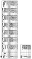
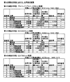
図11の表に、第1区間の概略光路長と、第2〜第9区間の概略光路長との差が示されている。第2〜8区間の概略光路長と第1区間の概略光路長との差は、波長655nmのDVD及び波長790nmのCDに対して、それぞれmλ(mは整数)となっており、波長405nmのHDDVDに対して、2mλ(mは整数)となっている。 The table of FIG. 11 shows the difference between the approximate optical path length of the first section and the approximate optical path length of the second to ninth sections. The difference between the approximate optical path length of the second to eighth sections and the approximate optical path length of the first section is mλ (m is an integer) for a DVD with a wavelength of 655 nm and a CD with a wavelength of 790 nm. For HDDVD, it is 2 mλ (m is an integer).
このように、第1の実施形態は、収差を上記の許容値内に抑えることができる。これは、各波長と各基板厚を考慮して、収差がかかる許容値内に収まるようなレンズ面形状及び、対物レンズへの入射光線の発散度合いを設定していることによる。
第1の実施形態では、総合的な収差が低減されていることが、図10に示す光スポット及び図2に示す波面収差のグラフから明らかである。また、第1の実施形態では、対物レンズ1の光入射側面Aの面形状は式(5)及び図7で与えられ、光出射側面Bの面形状は式(6)及び図8に示す非球面の式により与えられる。それ故、先に説明した従来のレンズ(例えば、特許文献1、2におけるレンズ)のような回折レンズ構造が採用されていない。また、第1の実施形態では、記録または再生に必要な開口(NA)に対してほぼ全ての光束を集光することができるので、高い光利用効率が得られることになる。
Thus, the first embodiment can suppress the aberration within the allowable value. This is because in consideration of each wavelength and each substrate thickness, the lens surface shape is set so that the aberration falls within the allowable value, and the degree of divergence of the incident light to the objective lens is set.
In the first embodiment, it is clear from the graph of the light spot shown in FIG. 10 and the wavefront aberration shown in FIG. 2 that the total aberration is reduced. Further, in the first embodiment, the surface shape of the light incident side surface A of the
なお、第1の実施形態では、HDDVDとDVDとCDとの3種類の光ディスクを例としたが、本発明は、これに限らず、これら以外の種類が異なる光ディスクであってもよい。またなお、第1の実施形態は、基板の厚みが同じや異なる光ディスクに対しても、適用可能であり、夫々毎に使用するレーザビームの波長を異ならせて、これらに応じて、総合収差が低減するように、レンズ面形状を設定すればよい。 In the first embodiment, three types of optical discs of HDDVD, DVD, and CD are used as examples. However, the present invention is not limited to this, and other types of optical discs may be used. The first embodiment can also be applied to optical discs having the same or different substrate thicknesses. The wavelength of the laser beam used for each of the optical discs is different, and the total aberration is accordingly changed. What is necessary is just to set a lens surface shape so that it may reduce.
発明の実施の形態2.
発明の実施の形態2(第2の実施形態)では、基板厚が異なり波長が405nmと655nmと790nmと異なる場合について説明する。詳細には、第2の実施形態は、いわゆるブルーレイ、ブルーレーザー使用の波長405nmで基板厚0.1mmである場合と、いわゆるDVD、波長655nmで基板厚0.6mmである場合と、いわゆるCD、波長790nmで基板厚1.2mmである場合に関するものである。
In the second embodiment (second embodiment) of the invention, a case where the substrate thickness is different and the wavelengths are different from 405 nm, 655 nm, and 790 nm will be described. Specifically, in the second embodiment, when using a so-called Blu-ray or blue laser with a wavelength of 405 nm and a substrate thickness of 0.1 mm, so-called DVD, when the wavelength is 655 nm and the substrate thickness is 0.6 mm, so-called CD, This relates to a case where the wavelength is 790 nm and the substrate thickness is 1.2 mm.
第2の実施形態では、基本的なレンズ構成は図6に示された第1の実施形態と同じである。すなわち、ブルーレイとDVDについては、A面側より平行光を入射させてB面側にあるディスク基板(図示しない)の記録面上に良好な光スポットが形成されている。CDについては、A面側より発散光を入射させてB面側にあるディスク基板(図示しない)の記録面上に良好な光スポットが形成されている。 In the second embodiment, the basic lens configuration is the same as that of the first embodiment shown in FIG. That is, for Blu-ray and DVD, parallel light is incident from the A side and a good light spot is formed on the recording surface of the disk substrate (not shown) on the B side. For CD, divergent light is incident from the A side, and a good light spot is formed on the recording surface of a disk substrate (not shown) on the B side.
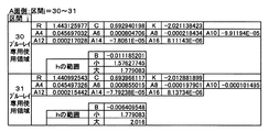
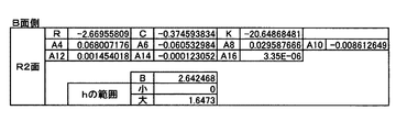
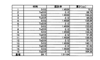
光源側のA面は、式(5)によりZAとhの関係が表される。その具体的な数値は、図12乃至図15の表に区間1〜22ごとに示されている。また光源と反対側、ディスク側のB面は、式(6)でZBとhの関係が表される。その具体的な数値は、図16に示されている。なお、図12乃至図16において、Rは曲率半径を、「小」は光軸側を、「大」は光軸から離れた側をそれぞれ示す。 A surface of the light source side, the relationship between Z A and h is represented by the formula (5). The specific numerical value is shown for every section 1-22 in the table | surface of FIG. 12 thru | or FIG. Further, the B surface on the side opposite to the light source and on the disk side represents the relationship between Z B and h in Expression (6). The specific numerical values are shown in FIG. 12 to 16, R represents a radius of curvature, “small” represents the optical axis side, and “large” represents the side away from the optical axis.
ちなみに、第2実施形態の対物レンズの屈折率は、高屈折率なガラス、例えばVC89の屈折率に近い値である。
また、対物レンズの光軸上の面頂点f,e間の距離、即ち、中心厚さt0は2.076mmである。さらに、波長λ1=405nm(ブルーレイディスク)での屈折率nは1.83164であり、波長λ2=655nm(DVD)での屈折率nは1.7911であり、λ3=790nm(CD)での屈折率nは1.783555である。
Incidentally, the refractive index of the objective lens of the second embodiment is a value close to the refractive index of glass having a high refractive index, for example, VC89.
Further, the surface vertex f of the optical axis of the objective lens, the distance between the e, that is, the center thickness t 0 is 2.076Mm. Further, the refractive index n at the wavelength λ 1 = 405 nm (Blu-ray Disc) is 1.83164, the refractive index n at the wavelength λ 2 = 655 nm (DVD) is 1.7911, and λ 3 = 790 nm (CD). The refractive index n is 1.783555.
透明基板の厚さと屈折率は、波長λ1=405nm(ブルーレイディスク)では、厚み0.6mmで屈折率1.6235である。さらに、波長λ2=655nm(DVD)では厚み0.6mmで屈折率は1.58であり、波長λ3=790nm(CD)では厚み1.2mmで屈折率は1.573である。従って、波長λ1=405nm(ブルーレイディスク)と波長λ2=655nm(DVD)のそれぞれの屈折率の差は0.03以上あり、波長λ1=405nm(ブルーレイディスク)と波長λ3=790nm(CD)のそれぞれの屈折率の差も0.03以上ある。 The thickness and refractive index of the transparent substrate are 0.6 mm and a refractive index of 1.6235 at a wavelength of λ 1 = 405 nm (Blu-ray Disc). Furthermore, the wavelength λ 2 = 655 nm (DVD) has a thickness of 0.6 mm and a refractive index of 1.58, and the wavelength λ 3 = 790 nm (CD) has a thickness of 1.2 mm and a refractive index of 1.573. Therefore, the difference in refractive index between the wavelength λ 1 = 405 nm (Blu-ray disc) and the wavelength λ 2 = 655 nm (DVD) is 0.03 or more, and the wavelength λ 1 = 405 nm (Blu-ray disc) and the wavelength λ 3 = 790 nm ( The difference in refractive index between CD) is also 0.03 or more.
また、波長405nmのブルーレイディスクの場合、NAは0.850、焦点距離は1.765mmであり、波長655nmのDVDの場合、NAは0.600で、焦点距離は1.8564mmであり、波長790nmのCDの場合、NAは0.469で、焦点距離は1.8745mmである。また各絞り径については、図17に示す通りであり、絞りについては第1実施形態と同様に波長選択性フィルターを用いている。 In the case of a 405 nm wavelength Blu-ray disc, the NA is 0.850 and the focal length is 1.765 mm. In the case of a DVD with a wavelength of 655 nm, the NA is 0.600, the focal length is 1.8564 mm, and the wavelength is 790 nm. In the case of CD, NA is 0.469 and the focal length is 1.8745 mm. Further, each aperture diameter is as shown in FIG. 17, and a wavelength selective filter is used for the aperture as in the first embodiment.
図17の表に、ブルーレイ、DVD、CDにおいて対物レンズを基準とした図12乃至図16に相当する光学系における、各光学要素間の距離、配置が示されている。図17は、絞り、対物レンズ、ディスクについて、また対物レンズにとっての物体面を表している。図17に示すように、例えば、ブルーレイやDVDでは、対物レンズへの入射光は平行光、つまり対物レンズにとっての物体面と対物レンズとの距離は∞となっている。現実の光学系の場合には、コリメータレンズの焦点位置にブルーレーザー、DVDレーザーを配置してコリメータレンズ出射光を平行光として対物レンズに入射させるようにする。 The table of FIG. 17 shows the distance and arrangement between the optical elements in the optical system corresponding to FIGS. 12 to 16 with reference to the objective lens in Blu-ray, DVD and CD. FIG. 17 shows the object plane for the stop, objective lens, disk and for the objective lens. As shown in FIG. 17, for example, in Blu-ray or DVD, the incident light to the objective lens is parallel light, that is, the distance between the object plane and the objective lens for the objective lens is ∞. In the case of an actual optical system, a blue laser and a DVD laser are arranged at the focal position of the collimator lens so that the collimator lens emission light enters the objective lens as parallel light.
CDの場合には、対物レンズとしては、物体面から対物レンズまでの距離は15.5mmであり、発散光を対物レンズに入射するようにする。このCDについても、現実の光学系の場合には、CDレーザーの発光点から対物レンズの光源側の面頂点までの距離を15.5mmとしてもよい。この場合には、光ピックアップが大型化してしまうことが懸念される。 In the case of CD, the objective lens has a distance of 15.5 mm from the object surface to the objective lens, and divergent light is incident on the objective lens. Also for this CD, in the case of an actual optical system, the distance from the light emitting point of the CD laser to the surface vertex on the light source side of the objective lens may be 15.5 mm. In this case, there is a concern that the optical pickup becomes large.
このような場合には、コリメータレンズをCDレーザー光源と対物レンズとの間に配置し、CDレーザーの発光点の位置をコリメータレンズの焦点位置よりもコリメータレンズに近いところに配置すればよい。これによって、CDレーザーを発してコリメータレンズを通過した光は発散光となり、対物レンズに入射する。その際、対物レンズへの入射光が、コリメータレンズ無しの状態で15.5mmの距離から発せられた光線入射状態と同じになるように、コリメータレンズとCDレーザーを配置すればよい。 In such a case, the collimator lens may be disposed between the CD laser light source and the objective lens, and the position of the light emission point of the CD laser may be disposed closer to the collimator lens than the focal position of the collimator lens. As a result, the light emitted from the CD laser and passed through the collimator lens becomes divergent light and enters the objective lens. At this time, the collimator lens and the CD laser may be arranged so that the incident light to the objective lens is the same as the light incident state emitted from a distance of 15.5 mm without the collimator lens.
図17に示された第2の実施形態について、式(1)、(2)に示すS1、S2、S3の関係について見てみると、
ブルーレイ;λ1=405nm S1=∞,
DVD ;λ2=655nm S2=∞,
CD ;λ3=790nm S3=15.5mm
であるから、
405nm(λ1)<790nm(λ3)
であり、
(1/S1)=(1/∞)=0、
(1/S3)=(1/15.5)=0.064516129
なので、
0<0.064516129、すなわち(1/S1)<(1/S3)
となる。
つまりブルーレイとCDにおいて、
λ1<λ3、かつ(1/S1)<(1/S3)
が成立している。
Regarding the second embodiment shown in FIG. 17, when looking at the relationship between S 1 , S 2 , and S 3 shown in equations (1) and (2),
Blu-ray; λ 1 = 405 nm S 1 = ∞,
DVD; λ 2 = 655 nm S 2 = ∞,
CD: λ 3 = 790 nm S 3 = 15.5 mm
Because
405 nm (λ 1 ) <790 nm (λ 3 )
And
(1 / S 1 ) = (1 / ∞) = 0,
(1 / S 3 ) = (1 / 15.5) = 0.0645516129
So,
0 <0.0645516129, ie (1 / S 1 ) <(1 / S 3 )
It becomes.
So in Blu-ray and CD,
λ 1 <λ 3 and (1 / S 1 ) <(1 / S 3 )
Is established.
また、
655nm(λ2)<790nm(λ3)
であり、
(1/S2)=(1/∞)=0,
(1/S3)=(1/15.5)=0.064516129
なので、
0<0.064516129、すなわち(1/S2)<(1/S3)
となる。
つまりDVDとCDにおいて、
λ2<λ3、かつ(1/S2)<(1/S3)
が成立している。
Also,
655 nm (λ 2 ) <790 nm (λ 3 )
And
(1 / S 2 ) = (1 / ∞) = 0,
(1 / S 3 ) = (1 / 15.5) = 0.0645516129
So,
0 <0.0645516129, ie (1 / S 2 ) <(1 / S 3 )
It becomes.
In other words, in DVD and CD,
λ 2 <λ 3 and (1 / S 2 ) <(1 / S 3 )
Is established.
図18からもわかるように、A面側の有効直径φ2.228まで、すなわちhの範囲で0〜1.114まで、つまり図18に示された区間1〜21までがDVDでもブルーレイでも使用する共通使用領域である。これに対して、φ2.228よりも外側の区間、すなわちhの範囲で1.114よりも大きい区間、つまり図18に示された区間22はブルーレイ専用使用領域である。
As can be seen from FIG. 18, the effective diameter on the A side is φ2.228, that is, 0 to 1.114 in the range of h, that is, the
しかし、このブルーレイ専用使用領域にも、DVDの場合にも、波長選択性フィルターではDVDの655nm光は透過する。このことから、入射レーザビーム光は入射し、その入射した光は、DVDの情報記録面上で収差が非常に大きい、いわゆるフレア光となって、有害な影響を与えないものとなっている。
このことは後述の図21の光スポット図からも説明される。
However, the wavelength selective filter transmits the 655 nm light of the DVD in both the Blu-ray exclusive use area and the DVD. For this reason, the incident laser beam light is incident, and the incident light becomes so-called flare light having very large aberration on the information recording surface of the DVD, and does not have a harmful effect.
This is also explained from the light spot diagram of FIG.
図19に、第2の実施形態の波面収差図が示されている。
なお、RMS波面収差値としては、ブルーレイのRMS波面収差が0.02410λRMSであり、DVDのRMS波面収差が0.02753λRMS、CDのRMS波面収差が0.02127λRMS、である。これらブルーレイディスクもDVDもCDも、それらのRMS波面収差が0.035λRMS以下、さらに0.033λRMS以下となっている。
式(7)の値については、
As the RMS wavefront aberration value, the RMS wavefront aberration of Blu-ray is 0.02410λRMS, the RMS wavefront aberration of DVD is 0.02753λRMS, and the RMS wavefront aberration of CD is 0.02127λRMS. These Blu-ray Discs, DVDs, and CDs have RMS wavefront aberrations of 0.035λ RMS or less, and further 0.033λ RMS or less.
For the value of equation (7),
また、図18には、図17に示した各非球面部において、第1区間の概略の光路長を基準とした時にブルーレイ/DVD共通使用領域第2〜21区間の概略光路長が、それぞれ概略で波長λの何倍ずれているかが示されている。 FIG. 18 also shows the approximate optical path lengths of the Blu-ray / DVD common use area Nos. 2 to 21 with respect to the approximate optical path length of the first period in each aspherical part shown in FIG. The figure shows how many times the wavelength λ is shifted.
図18よりわかるように、第2〜21区間が波長405nmのブルーレイに対しては2mλの差、波長655nmのDVD及び波長790nmのCDに対してはmλの差(mは整数)となっている。これは、短い方の波長λ1が380〜430nmの間に、長い方の波長λ2が波長630〜680nmの間にあり、λ3が波長790nm付近にあるので、上記した概略光路長の差の関係を満足しやすく、また図19に示す良好な波面収差を得やすくなっている。
As can be seen from FIG. 18, the second to 21st sections have a difference of 2 mλ for Blu-ray with a wavelength of 405 nm, and a difference of mλ with respect to a DVD with a wavelength of 655 nm and a CD with a wavelength of 790 nm (m is an integer). . This is because the shorter wavelength λ 1 is between 380 and 430 nm, the longer wavelength λ 2 is between wavelengths 630 and 680 nm, and λ 3 is in the vicinity of
また、レンズの屈折率が上記に示した値であることからも、概略光路長の差や良好な波面収差を得やすい。具体的には、405nm時の屈折率と655nm時の屈折率との差が0.04054であり、405nm時の屈折率と790nm時の屈折率の差が0.048085である。これらの値の両者が0.03よりも大きいことから、概略光路長の差や良好な波面収差を得やすくなっている。 In addition, since the refractive index of the lens is the value shown above, it is easy to obtain an approximate difference in optical path length and good wavefront aberration. Specifically, the difference between the refractive index at 405 nm and the refractive index at 655 nm is 0.04054, and the difference between the refractive index at 405 nm and the refractive index at 790 nm is 0.048085. Since both of these values are larger than 0.03, it is easy to obtain an approximate difference in optical path length and good wavefront aberration.
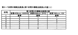
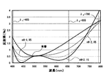
図20に、図17に示す各非球面部における405nmのブルーレイと655nmのDVDとの波面収差の差及びその比が示されている。
図20に示すように、655nmと405nmの共通使用領域において各波面収差の差の比ΔVd(λ655)/ΔVd(λ405)は、0.90〜1.65の間に入っている。また、比ΔVd(λ405)/ΔVd(λ655)は、0.60〜1.11の間に入っている。そして、その各領域の波面収差自体も両波長において0.14λ以下となっている。
FIG. 20 shows the difference in wavefront aberration between the 405 nm Blu-ray and the 655 nm DVD and the ratio thereof in each aspherical part shown in FIG.
As shown in FIG. 20, the ratio ΔVd (λ655) / ΔVd (λ405) of the difference between the wavefront aberrations in the common use region of 655 nm and 405 nm is between 0.90 and 1.65. The ratio ΔVd (λ405) / ΔVd (λ655) is between 0.60 and 1.11. The wavefront aberration of each region is also 0.14λ or less at both wavelengths.
図21に、第2の実施形態の光スポット図が示されている。図21に示すように、1/e2(=0.135)の相対光強度となる光スポット直径は、405nmのブルーレイのときで0.3836μm、655nmのDVDで0.8570μm、790nmのCDで1.4112μmとなっており、問題ない光スポット形状となっている。 FIG. 21 shows a light spot diagram of the second embodiment. As shown in FIG. 21, the diameter of the light spot with a relative light intensity of 1 / e 2 (= 0.135) is 0.3836 μm for 405 nm Blu-ray, 0.8570 μm for 655 nm DVD, and 570 nm for 790 nm CD. The light spot shape is 1.4112 μm and has no problem.
この光SPOT径を、第1実施形態のところで示した0.82×波長/NAの値と比較評価すると、次のようになる。
ブルーレイ(波長405nm、NA0.850)では、0.82×波長/NA=0.3907μmである。現実のSPOT径は、0.3836μmなので、0.82×波長/NAによるSPOT径の0.9818倍で、0.9〜1.02倍の間に入っている。
When this optical SPOT diameter is compared with the value of 0.82 × wavelength / NA shown in the first embodiment, it is as follows.
In Blu-ray (
DVD(波長655nm、NA0.600)では、0.82×波長/NA=0.8952μmである。現実のSPOT径は、0.8570μmなので、0.82×波長/NAによるSPOT径の0.9574倍で、0.9〜1.02倍の間に入っている。なお、このDVDでは約4%(0.04倍)も理想レンズに比べて光SPOT径が小さくなっている。これは、ブルーレイ専用領域部もDVD光が通過していて、その影響を受けて光SPOT径が小さくなっているためである。
For DVD (
CD(波長790nm、NA0.469)では、0.82×波長/NA=1.3812μmである。現実のSPOT径は、1.4084μmなので、0.82×波長/NAによるSPOT径の1.0197倍で、0.9〜1.02倍の間に入っている。
For CD (
なお、第2の実施形態では、一方の単色光の波長が405nm、他方が655nm、790nmであったが、一方が380〜430nm、他方が630〜680nm、770nm〜820nmでもよい。その場合には、屈折率が異なった値となるが、その値に合わせて設計すればよい。 In the second embodiment, the wavelength of one monochromatic light is 405 nm and the other is 655 nm and 790 nm, but one may be 380 to 430 nm and the other may be 630 to 680 nm and 770 to 820 nm. In that case, the refractive index becomes a different value, but it may be designed according to that value.
発明の実施の形態3.
発明の実施の形態3(第3の実施形態)では、3種類の光ディスク、即ち、HDDVD(λ1=408nm)とDVD(λ2=658nm)とCD(λ3=785nm)とを例に、図面を用いて説明する。第1の実施形態では対物レンズへの入射光線がHDDVD、DVDでは平行光、CDでは発散光であった。第3の実施形態では対物レンズへの入射光線がHDDVDでは収束光、DVDでは平行光、CDでは発散光の場合について説明する。なお、第3の実施形態の構成(HDDVD:収束光入射)は、第1の実施形態(HDDVD:平行光入射)と比べて、CDに対する物体距離を長くできる。対物レンズに発散光を入射させて使用する場合は、平行光を入射させて使用する場合に比べて、軸外で発生するコマ収差は大きくなる。従って、トラッキングのために対物レンズを光軸に略直交する面内で横ずれ(以下、対物レンズシフト)させた場合、コマ収差の発生量が大きくなってしまう問題が生じる。このコマ収差の発生量は光線の発散度が大きく影響する。発散度が小さい、すなわち物体距離が長いほうが、対物レンズシフト時のコマ収差の発生量を抑制できる。従って、第3の実施形態にかかる光学系の構成は、第1の実施形態の構成と比較して、CDの対物レンズシフトに対して有利である。ただし、HDDVDに対して収束光を入射させる構成としたので、HDDVDでも対物レンズシフト時にコマ収差がしてしまう。従って、HDDVD、CDでの物体距離(倍率)のバランスを考慮するのがよい。HDDVDの倍率m1、CDの倍率m3としたとき、
0<m1≦1/10、−1/10≦m3<0
を満足するのが好ましい。
上記範囲を外れると、対物レンズシフト時のコマ収差発生量が大きくなる。さらに好ましくは、次の範囲がよい。
0<m1≦1/20、−1/20≦m3<0
なお、第3の実施形態におけるレンズは、プラスチック樹脂相当の屈折率のものであるが、レンズ材質をガラスとしたい場合にはガラスの屈折率で設計すればよい。
In Embodiment 3 (Third Embodiment) of the invention, three types of optical disks, namely, HDDVD (λ 1 = 408 nm), DVD (λ 2 = 658 nm), and CD (λ 3 = 785 nm) are taken as examples. This will be described with reference to the drawings. In the first embodiment, light incident on the objective lens is parallel light on HDDVD and DVD, and divergent light on CD. In the third embodiment, a case will be described in which the incident light beam to the objective lens is convergent light in HDDVD, parallel light in DVD, and divergent light in CD. Note that the configuration of the third embodiment (HDDVD: convergent light incidence) can increase the object distance with respect to the CD as compared with the first embodiment (HDDVD: parallel light incidence). When the diverging light is incident on the objective lens and used, coma aberration generated off the axis is larger than when the parallel light is used. Therefore, when the objective lens is laterally shifted (hereinafter referred to as objective lens shift) in a plane substantially orthogonal to the optical axis for tracking, there arises a problem that the amount of coma aberration increases. The amount of coma aberration is greatly affected by the divergence of light rays. A smaller divergence, that is, a longer object distance, can suppress the amount of coma generated when the objective lens is shifted. Therefore, the configuration of the optical system according to the third embodiment is more advantageous for CD objective lens shift than the configuration of the first embodiment. However, since the converging light is made incident on the HDDVD, coma aberration occurs when the objective lens is shifted even in the HDDVD. Therefore, it is preferable to consider the balance of object distance (magnification) in HDDVD and CD. When the magnification of HDDVD is m1 and the magnification of CD is m3,
0 <m1 ≦ 1/10, −1 / 10 ≦ m3 <0
It is preferable to satisfy
Outside the above range, the amount of coma generated when the objective lens is shifted increases. More preferably, the following range is good.
0 <m1 ≦ 1/20, −1 / 20 ≦ m3 <0
The lens in the third embodiment has a refractive index equivalent to that of a plastic resin. However, when the lens material is glass, it may be designed with the refractive index of glass.
第3の実施形態の基本的なレンズ構成を第1の実施形態で示した図6にて説明する。第3の実施形態では、HDDVDはA面側より収束光を入射させてB面側にあるディスク基板(図示しない)の記録面上に良好な光スポットを形成している。DVDについては、A面側より平行光を入射させて、B面側にあるディスク基板(図示しない)の記録面上に良好な光スポットを形成している。CDについては、A面側より発散光を入射させてB面側にあるディスク基板(図示しない)の記録面上に良好な光スポットを形成している。
光源側のA面は、式(5)によりZAとhの関係が表される。その具体的な数値は、図22の表に区間1〜7ごとに示されている。
The basic lens configuration of the third embodiment will be described with reference to FIG. 6 shown in the first embodiment. In the third embodiment, in the HDDVD, convergent light is incident from the A side to form a good light spot on the recording surface of a disk substrate (not shown) on the B side. For DVD, parallel light is incident from the A side, and a good light spot is formed on the recording surface of a disk substrate (not shown) on the B side. For the CD, divergent light is incident from the A side to form a good light spot on the recording surface of the disk substrate (not shown) on the B side.
A surface of the light source side, the relationship between Z A and h is represented by the formula (5). The specific numerical values are shown for each of the
また、対物レンズの光軸上の面頂点f,e間の距離、即ち、中心厚さt0は1.92mmである。さらに、波長λ1=408nm(HDDVD)での屈折率nは1.5229であり、波長λ2=658nm(DVD)での屈折率nは1.5048であり、λ3=785nm(CD)での屈折率nは1.5018である。 Further, the distance between the surface vertices f and e on the optical axis of the objective lens, that is, the center thickness t 0 is 1.92 mm. Further, the refractive index n at the wavelength λ 1 = 408 nm (HDDVD) is 1.5229, the refractive index n at the wavelength λ 2 = 658 nm (DVD) is 1.5048, and λ 3 = 785 nm (CD). Has a refractive index n of 1.5018.
透明基板の厚さと屈折率は、波長λ1=408nm(HDDVD)では、厚み0.6mmで屈折率1.622である。さらに、波長λ2=658nm(DVD)では厚み0.6mmで屈折率は1.577であり、波長λ3=785nm(CD)では厚み1.2mmで屈折率は1.5720である。 The thickness and refractive index of the transparent substrate are 0.6 mm and a refractive index of 1.622 at a wavelength λ 1 = 408 nm (HDDVD). Furthermore, the wavelength λ 2 = 658 nm (DVD) has a thickness of 0.6 mm and a refractive index of 1.577, and the wavelength λ 3 = 785 nm (CD) has a thickness of 1.2 mm and a refractive index of 1.5720.
また、波長408nmのHDDVDの場合、NAは0.650、焦点距離は3.101mmであり、波長658nmのDVDの場合、NAは0.650で、焦点距離は3.2059mmであり、波長785nmのCDの場合、NAは0.470で、焦点距離は3.2246mmである。また各絞り径については、図23に示す通りであり、絞りについては第1実施形態と同様に波長選択性フィルターを用いている。 In the case of an HDDVD having a wavelength of 408 nm, the NA is 0.650 and the focal length is 3.101 mm. In the case of a DVD having a wavelength of 658 nm, the NA is 0.650, the focal length is 3.2059 mm, and the wavelength is 785 nm. In the case of CD, NA is 0.470 and the focal length is 3.2246 mm. Each aperture diameter is as shown in FIG. 23, and a wavelength selective filter is used for the aperture as in the first embodiment.
図23の表に、HDDVD、DVD、CDにおいて対物レンズを基準とした図1に相当する光学系における、各光学要素間の距離、配置が示されている。図23は、絞り、対物レンズ、ディスクについて、また対物レンズにとっての物体面を表している。図23に示すように、例えば、HDDVDでは対物レンズへの入射光は収束光である。従って、対物レンズにとっての物体面と対物レンズとの距離は負で表せ、−93.9mmとなる。現実の光学系ではコリメータレンズをHDDVDレーザー光源と対物レンズとの間に配置し、HDDVDレーザーの発光点の位置をコリメータレンズの焦点位置よりもコリメータレンズから遠いところに配置すればよい。これによって、HDDVDレーザーを発してコリメータレンズを通過した光は収束光となり、対物レンズに入射する。DVDでは、対物レンズへの入射光は平行光、つまり対物レンズにとっての物体面と対物レンズとの距離は∞となっている。現実の光学系の場合には、コリメータレンズの焦点位置に、DVDレーザーを配置してコリメータレンズの出射光を平行光として対物レンズに入射させるようにしている。 The table of FIG. 23 shows the distance and arrangement between the optical elements in the optical system corresponding to FIG. 1 with respect to the objective lens in HDDVD, DVD, and CD. FIG. 23 shows the object plane for the stop, objective lens, disk and for the objective lens. As shown in FIG. 23, for example, in HDDVD, the incident light to the objective lens is convergent light. Therefore, the distance between the object plane and the objective lens for the objective lens can be expressed as a negative value, which is -93.9 mm. In an actual optical system, a collimator lens may be disposed between the HDDVD laser light source and the objective lens, and the position of the light emitting point of the HDDVD laser may be disposed farther from the collimator lens than the focal position of the collimator lens. As a result, the light emitted from the HDDVD laser and passing through the collimator lens becomes convergent light and enters the objective lens. In DVD, the incident light to the objective lens is parallel light, that is, the distance between the object plane and the objective lens for the objective lens is ∞. In the case of an actual optical system, a DVD laser is arranged at the focal position of the collimator lens so that the light emitted from the collimator lens enters the objective lens as parallel light.
CDの場合には、物体面から対物レンズまでの距離は98.9mmであり、発散光が対物レンズに入射するようなレンズ構成としている。現実の光学系の場合に、CDレーザーの発光点から対物レンズの光源側の面頂点までの距離を98.9mmとするのでは、光ピックアップが大型化してしまう。従って、コリメータレンズをCDレーザー光源と対物レンズとの間に配置し、CDレーザーの発光点の位置をコリメータレンズの焦点位置よりもコリメータレンズに近いところに配置するのがよい。これによって、CDレーザーを発してコリメータレンズを通過した光は発散光となり、対物レンズに入射する。その際、対物レンズへの入射光が、コリメータレンズ無しの状態で98.9mmの距離から発せられた光線入射状態と同じになるように、コリメータレンズとCDレーザーを配置すればよい。 In the case of CD, the distance from the object surface to the objective lens is 98.9 mm, and the lens configuration is such that divergent light enters the objective lens. In the case of an actual optical system, if the distance from the light emitting point of the CD laser to the surface vertex on the light source side of the objective lens is 98.9 mm, the optical pickup becomes large. Therefore, it is preferable to dispose the collimator lens between the CD laser light source and the objective lens, and to arrange the emission point of the CD laser closer to the collimator lens than the focal position of the collimator lens. As a result, the light emitted from the CD laser and passed through the collimator lens becomes divergent light and enters the objective lens. At this time, the collimator lens and the CD laser may be arranged so that the incident light to the objective lens is the same as the light incident state emitted from a distance of 98.9 mm without the collimator lens.
図23に示された第3の実施形態について、式(1)、(2)に示すS1、S2、S3の関係について見てみると、
HDDVD;λ1=408nm S1=−93.9mm,
DVD ;λ2=658nm S2=∞,
CD ;λ3=785nm S3=113.0mm
であるから、
408nm(λ1)<785nm(λ3)
であり、
(1/S1)=(1/(−93.9))=−0.010649627
(1/S3)=(1/113.0)=0.008849557
なので、
−0.010649627<0.008849557、すなわち(1/S1)<(1/S3)
となる。
Regarding the third embodiment shown in FIG. 23, the relationship between S 1 , S 2 , and S 3 shown in equations (1) and (2) is as follows.
HDDVD; λ 1 = 408 nm S 1 = −93.9 mm,
DVD; λ 2 = 658 nm S 2 = ∞,
CD: λ 3 = 785 nm S 3 = 113.0 mm
Because
408 nm (λ 1 ) <785 nm (λ 3 )
And
(1 / S 1 ) = (1 / (− 93.9)) = − 0.010649627
(1 / S 3 ) = (1 / 113.0) = 0.008849557
So,
−0.010649627 <0.008849557, ie (1 / S 1 ) <(1 / S 3 )
It becomes.
つまりHDDVDとCDにおいて、
λ1<λ3、かつ(1/S1)<(1/S3)
が成立している。
また、HDDVDの倍率m1は、1/31.2、CDの倍率m3は−1/34.1となり、0<m1≦1/20、−1/20≦m3<0
を満足している。
In other words, in HDDVD and CD,
λ 1 <λ 3 and (1 / S 1 ) <(1 / S 3 )
Is established.
In addition, the magnification m1 of HDDVD is 1 / 31.2, and the magnification m3 of CD is −1 / 34.1, and 0 <m1 ≦ 1/20 and −1 / 20 ≦ m3 <0.
Is satisfied.
また、
658nm(λ2)<785nm(λ3)
であり、
(1/S2)=(1/∞)=0,
(1/S3)=(1/113.0)=0.008849557
なので、
0<0.008849557、すなわち(1/S2)<(1/S3)
となる。
Also,
658 nm (λ 2 ) <785 nm (λ 3 )
And
(1 / S 2 ) = (1 / ∞) = 0,
(1 / S 3 ) = (1 / 113.0) = 0.008849557
So,
0 <0.008849557, ie (1 / S 2 ) <(1 / S 3 )
It becomes.
つまりDVDとCDにおいて、
λ2<λ3、かつ(1/S2)<(1/S3)
が成立している。
In other words, in DVD and CD,
λ 2 <λ 3 and (1 / S 2 ) <(1 / S 3 )
Is established.
図22からもわかるように、A面側の有効直径φ3.8932mmまで、すなわちhの範囲で0〜1.94658まで、つまり図22に示された区間1〜6までがDVDでもHDDVDでも使用する共通使用領域である。これに対して、φ3.8932よりも外側の区間、すなわちhの範囲で1.94658よりも大きい区間、つまり図22に示された区間7はDVD専用使用領域である。
As can be seen from FIG. 22, the effective diameter on the A side is φ3.8932 mm, that is, 0 to 1.94658 in the range of h, that is, the
しかし、このDVD専用使用領域にも、HDDVDの場合にも、波長選択性フィルターではHDDVDの408nm光は透過する。このことから、HDDVDの場合においてレーザーから出射したレーザビーム光は対物レンズを経てHDDVDに入射することになるが、入射した光は、HDDVDの情報記録面上で収差が非常に大きい、いわゆるフレア光となるため悪影響を与えない。 However, the wavelength selective filter transmits the 408 nm light of HDDVD in both the DVD dedicated use area and HDDVD. Therefore, in the case of HDDVD, the laser beam emitted from the laser enters the HDDVD through the objective lens, but the incident light has a very large aberration on the information recording surface of the HDDVD, so-called flare light. It will not adversely affect.
あるいは、図24に示すような波長選択性フィルターを用いてもよい。波長選択性フィルターは図24に示すように、内側の全光透過領域61と中間のCD(785nm)光遮断領域62、さらに外側のHDDVD(408nm)、CD(785nm)光遮断領域63とに区分けされている。例えば、中間のCD光遮断領域62には750nm以上の光を反射するようなダイクロイックコーティング、外側のHDDVD、CD光遮断領域63には600〜700nmの光線のみ透過させるようなダイクロイックコーティングを施せばよい。
これによって、HDDVDのNA(開口数)は0.650、DVDのNAは0.650、CDのNAは0.470とすることができる。
Alternatively, a wavelength selective filter as shown in FIG. 24 may be used. As shown in FIG. 24, the wavelength selective filter is divided into an inner total
As a result, the NA (numerical aperture) of HDDVD can be 0.650, the NA of DVD can be 0.650, and the NA of CD can be 0.470.
図25に、第3の実施形態の波面収差図が示されている。
なお、RMS波面収差値としては、HDDVDのRMS波面収差が0.03253λRMSであり、DVDのRMS波面収差が0.03178λRMS、CDのRMS波面収差が0.02091λRMS、である。これらHDDVDもDVDもCDも、それらのRMS波面収差が0.035λRMS以下、さらに0.033λRMS以下となっている。
式(7)の値については、
As the RMS wavefront aberration value, the RMS wavefront aberration of HDDVD is 0.03253λRMS, the RMS wavefront aberration of DVD is 0.03178λRMS, and the RMS wavefront aberration of CD is 0.02091λRMS. These HDDVDs, DVDs, and CDs have RMS wavefront aberrations of 0.035λ RMS or less, and further 0.033λ RMS or less.
For the value of equation (7),
図26に第1の実施形態の対物レンズと第3の実施形態の対物レンズでのCD(NA0.470)対物レンズシフト0.3mm時におけるコマ収差(3次)の発生量を示す。第1の実施形態では対物レンズへの入射光線がHDDVD、DVDでは平行光、CDでは発散光の構成でCDの物体距離は49.4mmであった。第3の実施形態では対物レンズへの入射光線がHDDVDでは収束、DVDでは平行、CDでは発散の構成としたことで、CDの物体距離は113.0mmと第1の実施形態と比べて長くなっている。この結果、図26に示されるように、第1の実施形態の対物レンズでは0.0469λRMSあったCDの対物レンズシフト時のコマ収差発生量が、第3の実施形態の対物レンズでは0.0177λRMSに低減されている。 FIG. 26 shows the amount of coma aberration (third order) generated when the objective lens of the first embodiment and the objective lens of the third embodiment have a CD (NA 0.470) objective lens shift of 0.3 mm. In the first embodiment, the incident light to the objective lens is parallel light for HDDVD and DVD, and divergent light for CD, and the object distance of the CD is 49.4 mm. In the third embodiment, the incident light to the objective lens is converged in HDDVD, parallel in DVD, and divergent in CD, so that the object distance of CD is 113.0 mm, which is longer than that in the first embodiment. ing. As a result, as shown in FIG. 26, the amount of coma generated when the objective lens of the CD, which was 0.0469 λRMS in the objective lens of the first embodiment, is 0.0177 λRMS in the objective lens of the third embodiment. Has been reduced.
また、図27には、図22に示した各非球面部において、第1区間の概略の光路長を基準とした時にHDDVD/DVD共通使用領域第2〜6区間の概略光路長が、それぞれ概略で波長λの何倍ずれているかが示されている。 In addition, FIG. 27 shows the approximate optical path lengths of the HDDVD / DVD common use area in the second to sixth sections with reference to the approximate optical path length of the first section in each aspherical part shown in FIG. The figure shows how many times the wavelength λ is shifted.
図27よりわかるように、第2〜6区間が波長408nmのHDDVDに対しては2mλの差、波長658nmのDVD及び波長785nmのCDに対してはmλの差(mは整数)となっている。これは、短い方の波長λ1が380〜430nmの間に、長い方の波長λ2が波長630〜680nmの間にあり、λ3が波長785nm付近にあるので、上記した概略光路長の差の関係を満足しやすく、また図25に示す良好な波面収差を得やすくなっている。 As can be seen from FIG. 27, the second to sixth sections have a difference of 2 mλ for HD DVD having a wavelength of 408 nm, and a difference of mλ for DVD having a wavelength of 658 nm and a CD having a wavelength of 785 nm (m is an integer). . This is because the shorter wavelength λ 1 is between 380 and 430 nm, the longer wavelength λ 2 is between 630 and 680 nm, and λ 3 is near the wavelength of 785 nm. It is easy to satisfy this relationship, and it is easy to obtain the favorable wavefront aberration shown in FIG.
図28に、第3の実施形態の光スポット図が示されている。図28に示すように、1/e2(=0.135)の相対光強度となる光スポット直径は、408nmのHDDVDのときで0.5029μm、658nmのDVDで0.8236μm、785nmのCDで1.3811μmとなっており、問題ない光スポット形状となっている。 FIG. 28 shows a light spot diagram of the third embodiment. As shown in FIG. 28, the light spot diameter with a relative light intensity of 1 / e 2 (= 0.135) is 0.5029 μm for a 408 nm HDDVD, 0.8236 μm for a 658 nm DVD, and a CD of 785 nm. It is 1.3811 μm, and it has a light spot shape with no problem.
この光SPOT径を、第1の実施形態のところで示した0.82×波長/NAの値と比較評価すると、次のようになる。
HDDVD(波長408nm、NA0.650)では、0.82×波長/NA=0.5147μmである。現実のSPOT径は、0.5029μmなので、0.82×波長/NAによるSPOT径の0.9771倍で、0.9〜1.02倍の間に入っている。なお、このHDDVDでは約2.3%(0.023倍)も理想レンズに比べて光SPOT径が小さくなっている。これは、DVD専用領域部もHDDVD光が通過していて、その影響を受けて光SPOT径が小さくなっているためである。
When this optical SPOT diameter is compared with the value of 0.82 × wavelength / NA shown in the first embodiment, it is as follows.
In HDDVD (wavelength 408 nm, NA 0.650), 0.82 × wavelength / NA = 0.5147 μm. Since the actual SPOT diameter is 0.5029 μm, it is 0.9771 times the SPOT diameter of 0.82 × wavelength / NA and is in the range of 0.9 to 1.02. In this HDDVD, the optical spot diameter is about 2.3% (0.023 times) smaller than that of the ideal lens. This is because HDDVD light also passes through the DVD dedicated area, and the optical spot diameter is reduced due to the influence.
DVD(波長658nm、NA0.65)では、0.82×波長/NA=0.8301μmである。現実のSPOT径は、0.8236μmなので、0.82×波長/NAによるSPOT径の0.9922倍で、0.9〜1.02倍の間に入っている。
CD(波長785nm、NA0.470)では、0.82×波長/NA=1.3696μmである。現実のSPOT径は、1.3811μmなので、0.82×波長/NAによるSPOT径の1.0084倍で、0.9〜1.02倍の間に入っている。
In DVD (wavelength 658 nm, NA 0.65), 0.82 × wavelength / NA = 0.8301 μm. Since the actual SPOT diameter is 0.8236 μm, it is 0.9922 times the SPOT diameter by 0.82 × wavelength / NA and is in the range of 0.9 to 1.02.
For CD (wavelength 785 nm, NA 0.470), 0.82 × wavelength / NA = 1.696 μm. Since the actual SPOT diameter is 1.3811 μm, it is 1.0084 times the SPOT diameter of 0.82 × wavelength / NA and is in the range of 0.9 to 1.02.
なお、第3の実施形態では、単色光の波長は、それぞれ408nm、658nm、785nmであったが、380〜430nm、630〜680nm、770nm〜820nmでもよい。その場合には、屈折率が異なった値となるが、その値に合わせて設計すればよい。また、第1の実施形態では対物レンズへの入射光線がHDDVD、DVDでは平行光、CDでは発散光、第3の実施形態では対物レンズへの入射光線がHDDVDでは収束光、DVDでは平行光、CDでは発散光の構成としたが、この構成の組み合わせはこの限りではない。例えば、HDDVD収束、DVD収束、CD発散の構成をとることも可能である。ここで、HDDVD、DVDの物体距離を同じにしておけばHDDVD、DVDで同一の光検出器とすることも可能となる。 In the third embodiment, the wavelengths of monochromatic light are 408 nm, 658 nm, and 785 nm, respectively, but may be 380 to 430 nm, 630 to 680 nm, and 770 nm to 820 nm. In that case, the refractive index becomes a different value, but it may be designed according to that value. Further, in the first embodiment, the incident light beam to the objective lens is HDDVD and DVD, collimated light, CD is divergent light, in the third embodiment the incident light beam to the objective lens is HDDVD and convergent light, DVD is parallel light, The CD has a divergent light configuration, but this combination of configurations is not limited to this. For example, it is possible to adopt a configuration of HDDVD convergence, DVD convergence, and CD divergence. Here, if the object distance of HDDVD and DVD is the same, the same photodetector can be used for HDDVD and DVD.
発明の実施の形態4.
発明の実施の形態4(第4の実施形態)では、第2の実施形態と同じく基板厚が異なり、波長が408nmと655nmと790nmと異なる例であって、第2の実施形態で示した対物レンズの材質とは異なる材質のレンズを用いて対物レンズを実施した場合について説明する。
The fourth embodiment of the invention (fourth embodiment) is an example in which the substrate thickness is different from the second embodiment and the wavelengths are different from 408 nm, 655 nm, and 790 nm, and the objective shown in the second embodiment is shown. A case where the objective lens is implemented using a lens made of a material different from the lens material will be described.
第2の実施形態では、対物レンズの材質として、例えばVC89のような融点・熱変形温度(Tg=528℃)の高いガラスを念頭においている。それに対して、第4の実施形態では、対物レンズの材質として、例えば住田光学ガラス社製のK−PG325のような融点・熱変形温度(Tg=288℃)の低いガラスを念頭においている。このような第2の実施形態と第4の実施形態における対物レンズの材質の違いについて、以下に比較説明する。 In the second embodiment, as a material of the objective lens, for example, glass having a high melting point / heat distortion temperature (Tg = 528 ° C.) such as VC89 is considered. On the other hand, in the fourth embodiment, as a material of the objective lens, for example, a glass having a low melting point and heat distortion temperature (Tg = 288 ° C.) such as K-PG325 manufactured by Sumita Optical Glass Co., Ltd. is considered. The difference in the material of the objective lens between the second embodiment and the fourth embodiment will be described below in comparison.
VC89のような高屈折率なガラスは、その材質の融点が600度以上と高いため、その温度に耐えうるレンズ成型の金型として、金型表面に微細構造を刻むことが難しい超硬の金型を必要とする。またレンズ成型後、常温までの温度低下に相当の時間を要するため、時間当たりの生産性が低いといった問題もある。一方、K−PG325のような屈折率の低いガラスは、その材質の融点が300度程度と低いので、レンズ成型の金型としてプラスチック系の材質で用いる金型と同等のものが流用でき、金型に輪帯のような微細構造を刻むことが容易である。また、常温までの温度低下に要する時間も短いため、時間当たりの生産性が高いといった利点もある。以下では、K−PG325のような屈折率が1.49から1.70かつ熱変形温度が300度以下のガラスを主成分とする材料を低融点ガラスと呼ぶことにする。 A high refractive index glass such as VC89 has a high melting point of 600 ° C. or more, so that it is difficult to engrave a fine structure on the mold surface as a lens mold that can withstand that temperature. Requires a type. Moreover, since it takes a considerable time to lower the temperature to room temperature after molding the lens, there is a problem that productivity per hour is low. On the other hand, a glass having a low refractive index such as K-PG325 has a low melting point of about 300 ° C., so that the same mold as that used for plastic materials can be used as a mold for lens molding. It is easy to engrave a fine structure such as a ring zone in the mold. In addition, since the time required for temperature reduction to room temperature is short, there is an advantage that productivity per hour is high. Hereinafter, a material mainly composed of glass having a refractive index of 1.49 to 1.70 and a heat distortion temperature of 300 ° C. or lower, such as K-PG325, will be referred to as low melting point glass.
しかしながら、低融点ガラスの屈折率は、例えば、408nmの光線に対して1.49〜1.70であり、一般的なVC89のようなガラスと比べると屈折率が小さい点に難がある。従って、低融点ガラスは、屈折率が小さいので、高NAのレンズを光学設計しにくい。本実施の形態では、レンズ中心の厚さを2.642mmと通常よりも大きくすることで、低融点ガラスを対物レンズの材質として用いた場合の特性を確保している。なお、低融点ガラスの屈折率はプラスチック系の材質とほぼ同等であるが、低融点ガラスは特にプラスチック系の材質に比べて高い温度湿度特性を有する点で、対物レンズの材質としてプラスチック系の材質に比べて有利である。 However, the refractive index of the low-melting glass is, for example, 1.49 to 1.70 with respect to a light beam having a wavelength of 408 nm, and there is a difficulty in that the refractive index is small compared to a glass such as a general VC89. Therefore, since the low melting point glass has a small refractive index, it is difficult to optically design a high NA lens. In the present embodiment, the thickness at the center of the lens is set to 2.642 mm, which is larger than usual, to ensure the characteristics when the low melting point glass is used as the material of the objective lens. The refractive index of low-melting glass is almost the same as that of plastic materials. However, low-melting glass has high temperature and humidity characteristics compared to plastic materials. It is advantageous compared to
詳細には、第4の実施形態は、いわゆるブルーレイ、ブルーレーザー使用の波長408nmで基板厚0.0875mmである場合と、いわゆるDVD、波長655nmで基板厚0.6mmである場合と、いわゆるCD、波長790nmで基板厚1.2mmである場合に関するものであり、レンズの材質として上記低融点ガラスを用いることを特徴とする。 Specifically, the fourth embodiment includes a so-called Blu-ray and blue laser using a wavelength of 408 nm and a substrate thickness of 0.0875 mm, a so-called DVD, a wavelength of 655 nm and a substrate thickness of 0.6 mm, and a so-called CD. This relates to a case where the wavelength is 790 nm and the substrate thickness is 1.2 mm, and the low-melting glass is used as the material of the lens.
第4の実施形態では、基本的なレンズ構成は図6に示された第1の実施形態と同じである。すなわち、ブルーレイとDVDについては、A面側より平行光を入射させてB面側にあるディスク基板(図示しない)の記録面上に良好な光スポットが形成されている。CDについては、A面側より発散光を入射させてB面側にあるディスク基板(図示しない)の記録面上に良好な光スポットが形成されている。 In the fourth embodiment, the basic lens configuration is the same as that of the first embodiment shown in FIG. That is, for Blu-ray and DVD, parallel light is incident from the A side and a good light spot is formed on the recording surface of the disk substrate (not shown) on the B side. For CD, divergent light is incident from the A side, and a good light spot is formed on the recording surface of a disk substrate (not shown) on the B side.
光源側のA面は、式(5)によりZAとhの関係が表される。その具体的な数値は、図29、図30、図31、図32、図33、図34の表に区間ごとに示されている。また光源と反対側、ディスク側のB面は、式(6)でZBとhの関係が表される。その具体的な数値は、図35に示されている。なお、図29乃至図35において、Rは曲率半径を、「小」は光軸側を、「大」は光軸から離れた側をそれぞれ示す。
また、対物レンズの光軸上の面頂点f,e間の距離、即ち、中心厚さt0は2.642mmである。さらに、波長λ1=408nm(ブルーレイディスク)での屈折率nは1.5126であり、波長λ2=655nm(DVD)での屈折率nは1.4987であり、λ3=790nm(CD)での屈折率nは1.4958である。
A surface of the light source side, the relationship between Z A and h is represented by the formula (5). The specific numerical values are shown for each section in the tables of FIGS. 29, 30, 31, 32, 33, and 34. Further, the B surface on the side opposite to the light source and on the disk side represents the relationship between Z B and h in Expression (6). The specific numerical values are shown in FIG. 29 to 35, R represents a radius of curvature, “small” represents the optical axis side, and “large” represents the side away from the optical axis.
Further, the distance between the surface vertices f and e on the optical axis of the objective lens, that is, the center thickness t 0 is 2.642 mm. Further, the refractive index n at the wavelength λ 1 = 408 nm (Blu-ray Disc) is 1.5126, the refractive index n at the wavelength λ 2 = 655 nm (DVD) is 1.4987, and λ 3 = 790 nm (CD). The refractive index n is 1.4958.
透明基板の厚さと屈折率は、波長λ1=408nm(ブルーレイディスク)では、厚み0.0875mmで屈折率1.6205である。さらに、波長λ2=655nm(DVD)では厚み0.6mmで屈折率は1.5794であり、波長λ3=790nm(CD)では厚み1.2mmで屈折率は1.5725である。従って、波長λ1=408nm(ブルーレイディスク)と波長λ2=655nm(DVD)のそれぞれの屈折率の差は0.03以上あり、波長λ1=408nm(ブルーレイディスク)と波長λ3=790nm(CD)のそれぞれの屈折率の差も0.03以上ある。 The thickness and refractive index of the transparent substrate are 0.0875 mm and a refractive index of 1.6205 at the wavelength λ 1 = 408 nm (Blu-ray Disc). Furthermore, the wavelength λ 2 = 655 nm (DVD) has a thickness of 0.6 mm and a refractive index of 1.5794, and the wavelength λ 3 = 790 nm (CD) has a thickness of 1.2 mm and a refractive index of 1.5725. Thus, the difference in the respective refractive index of the wavelength lambda 1 = 408 nm (Blu-ray Disc) and wavelength lambda 2 = 655 nm (DVD) is 0.03, the wavelength lambda 1 = 408 nm and (Blu-ray Disc) wavelength lambda 3 = 790 nm ( The difference in refractive index between CD) is also 0.03 or more.
また、波長408nmのブルーレイディスクの場合、NAは0.850、焦点距離は2.3721mmであり、波長655nmのDVDの場合、NAは0.650で、焦点距離は2.4262mmであり、波長790nmのCDの場合、NAは0.510で、焦点距離は2.4378mmである。また各絞り径については、図36に示す通りであり、絞りについては第1実施形態と同様に波長選択性フィルターを用いている。 In the case of a Blu-ray disc having a wavelength of 408 nm, NA is 0.850 and the focal length is 2.3721 mm. In the case of a DVD having a wavelength of 655 nm, the NA is 0.650, the focal length is 2.4262 mm, and the wavelength is 790 nm. In the case of CD, NA is 0.510 and the focal length is 2.4378 mm. In addition, each aperture diameter is as shown in FIG. 36, and a wavelength selective filter is used for the aperture as in the first embodiment.
図36の表に、ブルーレイ、DVD、CDにおいて対物レンズを基準とした図29乃至図35に相当する光学系における、各光学要素間の距離、配置が示されている。図47は、絞り、対物レンズ、ディスクについて、また対物レンズにとっての物体面を表している。図36に示すように、例えば、ブルーレイやDVDでは、対物レンズへの入射光は平行光、つまり対物レンズにとっての物体面と対物レンズとの距離は∞となっている。現実の光学系の場合には、コリメータレンズの焦点位置にブルーレーザー、DVDレーザーを配置してコリメータレンズの出射光を平行光として対物レンズに入射させるようにする。 The table of FIG. 36 shows the distance and arrangement between the optical elements in the optical system corresponding to FIGS. 29 to 35 with reference to the objective lens in Blu-ray, DVD, and CD. FIG. 47 represents the object plane for the stop, objective lens, disk and for the objective lens. As shown in FIG. 36, for example, in Blu-ray or DVD, the incident light to the objective lens is parallel light, that is, the distance between the object plane for the objective lens and the objective lens is ∞. In the case of an actual optical system, a blue laser and a DVD laser are arranged at the focal position of the collimator lens so that the light emitted from the collimator lens enters the objective lens as parallel light.
CDの場合には、対物レンズとしては、物体面から対物レンズまでの距離は19.35mmであり、発散光を対物レンズに入射するようにする。このCDについても、現実の光学系の場合には、CDレーザーの発光点から対物レンズの光源側の面頂点までの距離を19.35mmとしてもよい。この場合には、光ピックアップが大型化してしまうことが懸念される。 In the case of CD, the objective lens has a distance from the object plane to the objective lens of 19.35 mm, and divergent light is incident on the objective lens. Also for this CD, in the case of an actual optical system, the distance from the light emitting point of the CD laser to the surface vertex on the light source side of the objective lens may be 19.35 mm. In this case, there is a concern that the optical pickup becomes large.
このような場合には、コリメータレンズをCDレーザー光源と対物レンズとの間に配置し、CDレーザーの発光点の位置をコリメータレンズの焦点位置よりもコリメータレンズに近いところに配置すればよい。これによって、CDレーザーを発してコリメータレンズを通過した光は発散光となり、対物レンズに入射する。その際、対物レンズへの入射光が、コリメータレンズ無しの状態で19.35mmの距離から発せられた光線入射状態と同じになるように、コリメータレンズとCDレーザーを配置すればよい。 In such a case, the collimator lens may be disposed between the CD laser light source and the objective lens, and the position of the light emission point of the CD laser may be disposed closer to the collimator lens than the focal position of the collimator lens. As a result, the light emitted from the CD laser and passed through the collimator lens becomes divergent light and enters the objective lens. At this time, the collimator lens and the CD laser may be arranged so that the incident light to the objective lens is the same as the light incident state emitted from a distance of 19.35 mm without the collimator lens.
図36に示された第4の実施形態について、式(1)、(2)に示すS1、S2、S3の関係について見てみると、
ブルーレイ;λ1=408nm S1=∞,
DVD ;λ2=655nm S2=∞,
CD ;λ3=790nm S3=19.35mm
であるから、
408nm(λ1)<790nm(λ3)
であり、
(1/S1)=(1/∞)=0,
(1/S3)=(1/19.35)=0.05168
なので、
0<0.05168、すなわち(1/S1)<(1/S3)
となる。
つまりブルーレイとCDにおいて、
λ1<λ3、かつ(1/S1)<(1/S3)
が成立している。
With regard to the fourth embodiment shown in FIG. 36, the relationship between S 1 , S 2 , and S 3 shown in equations (1) and (2) is as follows.
Blu-ray; λ 1 = 408 nm S 1 = ∞,
DVD; λ 2 = 655 nm S 2 = ∞,
CD: λ 3 = 790 nm S 3 = 19.35 mm
Because
408 nm (λ 1 ) <790 nm (λ 3 )
And
(1 / S 1 ) = (1 / ∞) = 0,
(1 / S 3 ) = (1 / 19.35) = 0.05168
So,
0 <0.05168, ie (1 / S 1 ) <(1 / S 3 )
It becomes.
So in Blu-ray and CD,
λ 1 <λ 3 and (1 / S 1 ) <(1 / S 3 )
Is established.
また、
655nm(λ2)<790nm(λ3)
であり、
(1/S2)=(1/∞)=0,
(1/S3)=(1/19.35)=0.05168
なので、
0<0.05168、すなわち(1/S2)<(1/S3)
となる。
つまりDVDとCDにおいて、
λ2<λ3、かつ(1/S2)<(1/S3)
が成立している。
Also,
655 nm (λ 2 ) <790 nm (λ 3 )
And
(1 / S 2 ) = (1 / ∞) = 0,
(1 / S 3 ) = (1 / 19.35) = 0.05168
So,
0 <0.05168, ie (1 / S 2 ) <(1 / S 3 )
It becomes.
In other words, in DVD and CD,
λ 2 <λ 3 and (1 / S 2 ) <(1 / S 3 )
Is established.
図37からもわかるように、A面側の有効直径φ3.153まで、すなわちhの範囲で0〜1.5765まで、つまり図37に示された区間1〜29までがDVDでもブルーレイでも使用する共通使用領域である。これに対して、φ3.153よりも外側の区間、すなわちhの範囲で1.5765よりも大きい区間、つまり図37に示された区間30及び区間31はブルーレイ専用使用領域である。
しかし、このブルーレイ専用使用領域にも、DVDの場合にも、波長選択性フィルターではDVDの655nm光は透過する。このことから、入射レーザビーム光は入射し、その入射した光は、DVDの情報記録面上で収差が非常に大きい、いわゆるフレア光となっているので悪影響を与えない。
As can be seen from FIG. 37, the effective diameter on the A side is φ3.153, that is, 0 to 1.5765 in the range of h, that is, the
However, the wavelength selective filter transmits the 655 nm light of the DVD in both the Blu-ray exclusive use area and the DVD. For this reason, incident laser beam light is incident, and the incident light is so-called flare light that has a very large aberration on the information recording surface of the DVD, so that it does not have an adverse effect.
図38に、第4の実施形態の波面収差図が示されている。
なお、RMS波面収差値としては、ブルーレイのRMS波面収差が0.03210λRMSであり、DVDのRMS波面収差が0.03740λRMS、CDのRMS波面収差が0.04320λRMS、である。これらブルーレイディスクもDVDもCDも、それらのRMS波面収差が0.045λRMS以下となっている。
また、図37には、図36に示した各非球面部において、第1区間の概略の光路長を基準とした時にブルーレイ/DVD共通使用領域第2〜29区間の概略光路長が、それぞれ概略で波長λの何倍ずれているかが示されている。
FIG. 38 shows a wavefront aberration diagram of the fourth embodiment.
As the RMS wavefront aberration value, the RMS wavefront aberration of Blu-ray is 0.03210λRMS, the RMS wavefront aberration of DVD is 0.03740λRMS, and the RMS wavefront aberration of CD is 0.04320λRMS. These Blu-ray Discs, DVDs and CDs have RMS wavefront aberrations of 0.045λ RMS or less.
FIG. 37 also shows the approximate optical path lengths of the Blu-ray / DVD common use area Nos. 2 to 29 with reference to the approximate optical path length of the first period in each aspherical portion shown in FIG. The figure shows how many times the wavelength λ is shifted.
図37よりわかるように、第2〜21区間が波長408nmのブルーレイに対しては2mλの差、波長655nmのDVD及び波長790nmのCDに対してはmλの差(mは整数)となっている。これは、短い方の波長λ1が380〜430nmの間に、長い方の波長λ2が波長630〜680nmの間にあり、λ3が波長790nm付近にあるので、上記した概略光路長の差の関係を満足しやすく、また図38に示す良好な波面収差を得やすくなっている。
As can be seen from FIG. 37, the second to 21st sections have a difference of 2 mλ for Blu-ray with a wavelength of 408 nm, and a difference of mλ with respect to a DVD with a wavelength of 655 nm and a CD with a wavelength of 790 nm (m is an integer). . This is because the shorter wavelength λ 1 is between 380 and 430 nm, the longer wavelength λ 2 is between wavelengths 630 and 680 nm, and λ 3 is in the vicinity of
なお、第4の実施形態では、単色光の波長は、408nm、655nm、790nmであったが、380〜430nm、630〜680nm、770nm〜820nmでもよい。その場合には、屈折率が異なった値となるが、その値に合わせて設計すればよい。 In the fourth embodiment, the wavelength of monochromatic light is 408 nm, 655 nm, and 790 nm, but may be 380 to 430 nm, 630 to 680 nm, and 770 nm to 820 nm. In that case, the refractive index becomes a different value, but it may be designed according to that value.
以上、説明したように、第4の実施形態では、408nmの光線に対する屈折率が1.49から1.70のガラスを主成分とする材料によりNA=0.85の対物レンズを形成する点に特徴を有する、このような低屈折率の材料として、例えば、300度程度の融点が低い材料を用いることができるので、通常の金型を使用して製造でき、生産性を高めることができる。 As described above, in the fourth embodiment, an objective lens with NA = 0.85 is formed of a material mainly composed of glass having a refractive index of 1.49 to 1.70 with respect to a light beam of 408 nm. As such a low refractive index material having characteristics, for example, a material having a low melting point of about 300 degrees can be used, so that it can be manufactured using a normal mold and productivity can be increased.
発明の実施の形態5.
図39は16層コートによる波長選択性フィルター(シャープカットフィルター)の膜構成を示す図である。図に示されるように、この波長選択性フィルターは、SiO2の層とTa2O5の層が交互にBK7からなるガラス基板上に積層されて構成されている。図39に示す屈折率は、780nmの光線に対する値である。図40に、図39に示す構成を有する波長選択性フィルターの分光特性を示す。図に示されるように、CD波長の780nm〜790nmの透過率は、1%程度に抑えられており、良好な特性を有する。なお、図40に示す分光特性については、図39に示す膜構成の屈折率や膜厚が0.5〜1%程度、製造誤差等によりズレていても、同様の分光透過率特性を得ることが可能である。
FIG. 39 is a diagram showing a film configuration of a wavelength selective filter (sharp cut filter) by 16-layer coating. As shown in the figure, this wavelength selective filter is configured by laminating SiO 2 layers and Ta 2 O 5 layers alternately on a glass substrate made of BK7. The refractive index shown in FIG. 39 is a value for a light beam of 780 nm. FIG. 40 shows the spectral characteristics of the wavelength selective filter having the configuration shown in FIG. As shown in the figure, the transmittance of the CD wavelength from 780 nm to 790 nm is suppressed to about 1%, and has good characteristics. Note that the spectral characteristics shown in FIG. 40 can be obtained even if the refractive index and film thickness of the film configuration shown in FIG. 39 are about 0.5 to 1% and are shifted due to manufacturing errors. Is possible.
その一方で、16層コートの場合には、コート数が多いためコスト高になる。図41は、10層コートによる波長選択性フィルターの膜構成を示す図である。図41に示す屈折率は、810nmの光線に対する値である。図42に、図41に示す構成を有する波長選択性フィルターの分光特性を示す。図に示されるように、CD波長の780nm〜790nmの透過率は7〜8%程度であるため、16層コートの波長選択性フィルターに比べてその特性は劣化しているが、CDの記録再生特性に悪影響を与えるほどではなく、実用に耐える程度である。10層コートによる波長選択性フィルターは、16層コートによる波長選択性フィルターに比べて原価低減を実現できる。なお、図42に示す分光特性については、図41に示す膜構成の屈折率や膜厚が0.5〜1%程度、製造誤差等によりズレていても、同様の分光透過率特性を得ることが可能である。 On the other hand, in the case of a 16-layer coat, the cost is high because the number of coats is large. FIG. 41 is a diagram showing a film configuration of a wavelength selective filter using a 10-layer coat. The refractive index shown in FIG. 41 is a value for a light beam of 810 nm. FIG. 42 shows spectral characteristics of the wavelength selective filter having the configuration shown in FIG. As shown in the figure, since the transmittance of CD wavelength from 780 nm to 790 nm is about 7 to 8%, the characteristics are deteriorated as compared with the 16-layer coated wavelength selective filter, but CD recording / reproduction is performed. It does not adversely affect the characteristics, but is practical enough to withstand. The wavelength selective filter with 10-layer coating can realize cost reduction compared to the wavelength-selective filter with 16-layer coating. Note that the spectral characteristics shown in FIG. 42 can be obtained even if the refractive index and film thickness of the film configuration shown in FIG. Is possible.
このように、波長選択性フィルターとしては、CD波長(770nm〜800nm)において、透過率が10%以下であることが好ましい。さらに好ましい範囲は、5%以下であり、最適な範囲は2%以下である。 Thus, as a wavelength selective filter, it is preferable that the transmittance | permeability is 10% or less in CD wavelength (770 nm-800 nm). A more preferable range is 5% or less, and an optimal range is 2% or less.
また、波長選択性フィルターとしては、ブルーレイやDVDの波長(380nm〜700nm)において、透過率が85%以上であることが好ましい。より好ましい範囲は、90%以上であり、95%以上であるとさらによい。最適な範囲は、97%以上である。 Moreover, as a wavelength selective filter, it is preferable that the transmittance | permeability is 85% or more in the wavelength (380 nm-700 nm) of Blu-ray or DVD. A more preferable range is 90% or more, and even more preferably 95% or more. The optimum range is 97% or more.
尚、図39〜図42に示す波長選択性フィルターは、対物レンズとは別に、ガラス基板上に形成したが、対物レンズの片方の面にコーティングすることによって形成してもよい。この場合、対物レンズの面のうち、平面に近いディスク側の面にコーティングすることが好ましい。これにより、均一な膜を容易に形成することができる。また、この際、波長選択性フィルターの屈折率とコーティングされる対物レンズの屈折率をほぼ等しくすることにより、図39〜図42で示した実施例におけるコーティング設計と同等の設計が実現可能となり、製作が容易となる。本実施例においてはプラスチック等の対物レンズの屈折率は1.54〜1.55であるのに対して、BK7の屈折率1.51となっており、両屈折率はほぼ等しい。波長選択性フィルターの屈折率は対物レンズの屈折率に対して、0.9から1.1の範囲にあるのが好ましい。 The wavelength selective filters shown in FIGS. 39 to 42 are formed on the glass substrate separately from the objective lens, but may be formed by coating on one surface of the objective lens. In this case, it is preferable to coat the surface on the disk side close to a flat surface among the surfaces of the objective lens. Thereby, a uniform film can be easily formed. At this time, by making the refractive index of the wavelength selective filter and the refractive index of the objective lens to be coated substantially equal, it becomes possible to realize a design equivalent to the coating design in the embodiments shown in FIGS. Manufacture is easy. In this embodiment, the refractive index of an objective lens such as plastic is 1.54 to 1.55, whereas the refractive index of BK7 is 1.51, and both refractive indexes are substantially equal. The refractive index of the wavelength selective filter is preferably in the range of 0.9 to 1.1 with respect to the refractive index of the objective lens.
発明の実施の形態6.
以下に、発明の実施の形態6(第6の実施形態)を図面を用いて詳細に説明する。本実施形態においては、光ピックアップ装置に含まれる光学部品として、光記憶媒体上にレーザー光を集光する対物レンズを例に説明する。また、当該光ピックアップ装置はCD,DVD及びブルーレイディスクに対応している。光学部品としては、対物レンズに限定されず、3種類の波長領域の光が通過する光学部材であれば本発明の効果を奏することができる。
The sixth embodiment (sixth embodiment) of the invention will be described below in detail with reference to the drawings. In the present embodiment, as an optical component included in the optical pickup device, an objective lens that focuses laser light on an optical storage medium will be described as an example. The optical pickup device is compatible with CDs, DVDs, and Blu-ray discs. The optical component is not limited to an objective lens, and the effect of the present invention can be achieved as long as it is an optical member through which light of three types of wavelength regions passes.
本発明に用いられる反射防止膜は光学部品上に高屈折率膜と低屈折率膜を順番に積層した構造からなる。高屈折率膜の材料としては、酸化アルミニウム、酸化ジルコニウム、酸化チタン、酸化タンタル、酸化ニオブ、酸化アンチモン、酸化セリウム、酸化イットリウム、酸化ハフニウム、酸化マグネシウム等の酸化物、窒化シリコン、窒化ゲルマニウム等の窒化物、炭化シリコン等の炭化物、硫化亜鉛等の硫化物、およびこれらの混合材から選ばれる少なくとも1種が、低屈折率膜の材料としては酸化シリコン、およびフッ化マグネシウム、フッ化アルミニウム、フッ化バリウム、フッ化カルシウム、フッ化リチウム、フッ化ナトリウム、フッ化ストロンチウム、フッ化イットリウム、チオライト、クライオライト(氷晶石)などのフッ化物、およびこれらの混合材から選ばれる少なくとも1種がある。また、高温高湿環境下での保存特性向上のためには、酸化物、窒化物、炭化物、フッ化物を用いることが望ましい。 The antireflection film used in the present invention has a structure in which a high refractive index film and a low refractive index film are sequentially laminated on an optical component. Materials for the high refractive index film include oxides such as aluminum oxide, zirconium oxide, titanium oxide, tantalum oxide, niobium oxide, antimony oxide, cerium oxide, yttrium oxide, hafnium oxide, magnesium oxide, silicon nitride, germanium nitride, etc. At least one selected from nitrides, carbides such as silicon carbide, sulfides such as zinc sulfide, and mixed materials thereof is used as a material for the low refractive index film, such as silicon oxide, magnesium fluoride, aluminum fluoride, fluorine. There is at least one selected from fluorides such as barium fluoride, calcium fluoride, lithium fluoride, sodium fluoride, strontium fluoride, yttrium fluoride, thiolite, cryolite (cryolite), and mixtures thereof . In addition, it is desirable to use oxides, nitrides, carbides, and fluorides in order to improve storage characteristics in a high temperature and high humidity environment.
本発明の反射防止膜は、例えば真空成膜法で作製される。真空成膜法には、真空蒸着法、スパッタ法、化学気相成長法、レーザブレイション法など各種成膜法を用いることができる。真空蒸着法を用いる場合、膜質を改善するため蒸気流の一部をイオン化するとともに基板側にバイアスを印加するイオンプレーティング法、クラスタイオンビーム法、別イオン銃を用いて基板にイオンを照射するイオンアシスト蒸着法を用いると有効である。スパッタ法としては、DC反応性スパッタ法、RFスパッタ法、イオンビームスパッタ法などがある。また、化学的気相法としては、プラズマ重合法、光アシスト気相法、熱分解法、有機金属化学気相法などがある。なお、各屈折率膜の膜厚は膜形成時の蒸着時間等を変えることで、所望の膜厚とすることができる。 The antireflection film of the present invention is produced by, for example, a vacuum film forming method. As the vacuum film forming method, various film forming methods such as a vacuum evaporation method, a sputtering method, a chemical vapor deposition method, and a laser brazing method can be used. When using vacuum deposition, ion is applied to the substrate using ion plating, a cluster ion beam method, or another ion gun that ionizes part of the vapor flow and applies a bias to the substrate to improve film quality. It is effective to use ion-assisted deposition. Examples of the sputtering method include a DC reactive sputtering method, an RF sputtering method, and an ion beam sputtering method. Further, examples of the chemical vapor phase method include a plasma polymerization method, a light-assisted vapor phase method, a thermal decomposition method, and a metal organic chemical vapor phase method. In addition, the film thickness of each refractive index film | membrane can be made into a desired film thickness by changing the vapor deposition time etc. at the time of film formation.
また、光学部品にはポリオレフィン系樹脂、シクロオレフィン系樹脂、メタクリル樹脂、ポリカーボネート樹脂等のプラスチック以外にも、石英ガラス、硼珪酸ガラスなどの光学ガラス、Al2O3、MgOなどの酸化物単結晶、多結晶基板、CaF2、MgF2、BaF2、LiFなどのフッ化物単結晶基板、多結晶基板、NaCl、KBr、KClなどの塩化物、臭化物単結晶、他結晶基板等の、使用帯域で透明な光学材料であれば、何れでも適用できる。このような反射防止膜の効果の原理を図43を用いて説明する。図43は上記のような、2層からなる反射防止膜を表面に設けた対物レンズ1を模式的に示した断面図である。反射防止膜は高屈折率層8及び低屈折率層7を有する。
In addition to plastics such as polyolefin resin, cycloolefin resin, methacrylic resin, and polycarbonate resin, optical parts include optical glass such as quartz glass and borosilicate glass, and oxide single crystals such as Al 2 O 3 and MgO. , Polycrystalline substrates, fluoride single crystal substrates such as CaF 2 , MgF 2 , BaF 2 , LiF, etc., polycrystalline substrates, chlorides such as NaCl, KBr, KCl, bromide single crystals, other crystal substrates, etc. Any transparent optical material can be applied. The principle of the effect of such an antireflection film will be described with reference to FIG. FIG. 43 is a cross-sectional view schematically showing the
このような対物レンズ1に光束Oが入射した場合の、反射光Rについて説明する。ここで、図43においては、便宜上光束Oに角度を付けて示しているが、光束Oは対物レンズ1の光軸に対して平行に入射する。光束Oは、まず低屈折率層7に入射する。低屈折率層7の表面で光束Oは透過光Pと反射光R1とに分かれる。次に透過光Pは低屈折率層7から高屈折率層8へ入射する。低屈折率層7と高屈折率層8との境界において、透過光Pは透過光Qと反射光R2とに分かれる。そして、透過光Qは高屈折率層8から対物レンズ1に達し、高屈折率層8と対物レンズ1との境界で反射し、反射光R3となる。
The reflected light R when the light beam O enters the
ここで、高屈折率層8と対物レンズ1との境界において、反射光R3とならずに対物レンズ1に入射する光束も存在するが、反射光Rを論じる上では必要ないので説明を省略する。また、反射光R2は低屈折率層7の上下の界面で反射率5%程度で多重反射する成分、および反射光R3は高屈折率層8の上下の界面で反射率5%程度で多重反射する成分とがあるが、これらの成分の光は2回以上反射すると光の強度は0.25%以下と微弱になるため、ここでは省略する。
Here, at the boundary between the high-
反射光Rは図43に示す反射光R1〜R3の合成波となる。従って、反射光R1〜R3の位相差によって、反射光Rの状態は変化する。反射光R1〜R2の位相差は、対物レンズ1、高屈折率層8の屈折率nH及び低屈折率層7の屈折率nLと、高屈折率層8及び低屈折率層7の光学膜厚と、光束Oの波長との関係により規定される。
The reflected light R is a composite wave of the reflected lights R1 to R3 shown in FIG. Therefore, the state of the reflected light R changes depending on the phase difference between the reflected lights R1 to R3. The phase difference between the reflected lights R1 and R2 is as follows: the
基本的な原理を説明すると、例えば低屈折率層7の光学膜厚が光束Oの波長の1/4であるとする。その場合、反射光R1と反射光R2との位相差は光束Oの1/2波長分であるため、反射光R1と反射光R2とは互いに打ち消し合う。結果的に反射光R3のみが反射光Rとなる。従って、当該波長領域においては光束Oに対する反射光R3の光強度の割合が反射率となる。他方、対物レンズ1、高屈折率層8及び低屈折率層7の条件はそのままに、光束Oの波長を変化させると、反射光R1〜R3が丁度打ち消し合う場合がある。当該波長領域においては反射率が低くなる。
The basic principle will be explained. For example, it is assumed that the optical film thickness of the low
このような原理を利用して、少なくともブルーレイディスクに用いられる光の波長(405nm程度)に対応する波長領域近傍と、DVDに用いられる光の波長(655nm程度)に対応する波長領域近傍とにおいて反射率が極小値を有し、CDに用いられる光の波長(790nm程度)に対応する波長領域においても低い反射率を示す反射防止膜を対物レンズ1表面に形成すれば、上記の3種類の光記憶媒体に対応する光ピックアップ装置として良好な性能を有することが期待できる。
Utilizing such a principle, reflection occurs at least in the vicinity of the wavelength region corresponding to the wavelength of light used for Blu-ray Disc (about 405 nm) and in the vicinity of the wavelength region corresponding to the wavelength of light used for DVD (about 655 nm). If an antireflection film having a minimum value and having a low reflectance in the wavelength region corresponding to the wavelength of light used for CD (about 790 nm) is formed on the surface of the
以下、上記した原理に基づき、対物レンズ1、高屈折率層8及び低屈折率層7の条件を設定し、シミュレーションした例を示す。以下に説明するシミュレーション例及び実施例において、高屈折率層8の膜厚dH及び低屈折率層の膜厚dLは所定の波長の1/4波長(QW)を基準に定められている。ここで言う所定の波長とは図43に示す光束Oの波長に相当し、本実施形態においては500nmである。本実施形態においては図43における説明と同様にnHdH(高屈折率層8の光学膜厚)=1QW程度であり、nLdL(低屈折率層7の光学膜厚)=2QW程度である。即ち、225nm≦nHdH≦275nm、100nm≦nLdL≦150nmである。
Hereinafter, based on the principle described above, an example in which the conditions of the
図44は対物レンズ1、低屈折率層7に対し、高屈折率層8の屈折率の変化に伴う上記の3種類の波長領域における反射率の変化をシミュレーションしたものである。夫々の波長領域における反射率の値は、波長405±5nm(以下、λ1とする)における反射率の最大値、波長655±20nm(以下、λ2とする)における反射率の最大値及び波長790±20nm(以下、λ3とする)における反射率の最小値を示す。また、nSは対物レンズの屈折率、nLは低屈折率層の屈折率、nHは高屈折率層の屈折率をそれぞれ示す。
FIG. 44 shows a simulation of the change in reflectivity in the above-described three types of wavelength regions with respect to the
図44(a)は対物レンズに三井化学株式会社製のAPEL(登録商標)を用い、低屈折率層としてSiO2を用いた場合の例である。図中、太線で囲われたデータは最も好ましいシミュレーション結果を示している。図45に、図44(a)の条件におけるnH=1.75、1.85、1.95及び低屈折率層単層の場合の波長に対する反射率の値のグラフを示す。図45に示すように、波長に対する反射率の値は、λ1近傍及びλ2近傍において極小値を有する二こぶの曲線であり、λ3においても、低い値を示している。アペル単体での反射率は4.5%であるため、反射防止膜を設けることによって所望の波長領域において反射率の低減が図られている。また、低屈折率層単層によるグラフを比較例としても、上記の3種類の波長領域において、いずれも反射率の低減が図られている。 FIG. 44A shows an example in which APEL (registered trademark) manufactured by Mitsui Chemicals, Inc. is used for the objective lens, and SiO 2 is used as the low refractive index layer. In the figure, the data surrounded by a thick line shows the most preferable simulation result. FIG. 45 shows a graph of reflectance values with respect to wavelength in the case of n H = 1.75, 1.85, 1.95 and a single low refractive index layer under the conditions of FIG. As shown in FIG. 45, the reflectance value with respect to the wavelength is a double-humped curve having a minimum value in the vicinity of λ 1 and λ 2 , and also shows a low value in λ 3 . Since the reflectance of the single apel is 4.5%, the reflectance is reduced in a desired wavelength region by providing an antireflection film. Moreover, even if the graph by a low refractive index layer single layer is used as a comparative example, the reflectance is reduced in each of the three types of wavelength regions.
図44(b)は、nS=1.70であり、これ以外の条件は図44(a)と同様である場合のシミュレーションである。図44(c)も同様であり、nS=1.85の場合のシミュレーションである。nHはnSよりも高くなければならないため、nS=1.54の場合に比べ、使用可能なnHの下限値が上がっており、データ量が減っている。 FIG. 44B is a simulation in the case where n S = 1.70 and other conditions are the same as those in FIG. The same applies to FIG. 44C, which is a simulation in the case of n S = 1.85. Since n H must be higher than n S , the lower limit value of n H that can be used is increased and the amount of data is reduced as compared to the case of n S = 1.54.
図46に、図44(c)の条件におけるnH=1.95、2.05、2.15及び低屈折率層単層の場合の波長に対する反射率の値のグラフを示す。図46に示すように、波長に対する反射率の値は、λ1近傍及びλ2近傍において極小値を有する。しかしながら、図45に示す曲線と比べて、λ2からλ3及びそれ以上の波長領域における反射率の変化が急峻であり、λ3においては、反射率がかなり高い値を示している。但し、図46における対物レンズ1の反射率は8.9%であるため、反射防止膜を設けることにより、反射率の低減は図られている。
FIG. 46 shows a graph of reflectance values with respect to wavelength in the case of n H = 1.95, 2.05, 2.15 and a low refractive index layer single layer under the conditions of FIG. As shown in FIG. 46, the reflectance with respect to the wavelength has a minimum value in the vicinity of λ 1 and in the vicinity of λ 2 . However, compared to the curve shown in FIG. 45, the change in reflectance in the wavelength region from λ 2 to λ 3 and beyond is steep, and the reflectance is considerably high at λ 3 . However, since the reflectance of the
また、図44(d)〜(f)は低屈折率層にMgF2を用い、nL=1.38とした場合である。図44(d)〜(f)においても、nS=1.54、1.70、1.85の夫々の場合におけるシミュレーションを行っている。図47に図44(d)の場合におけるnH=1.65、1.75、1.85及び低屈折率層単層の場合の波長に対する反射率の値のグラフを示す。図45と同様に、波長に対する反射率の値は、λ1近傍及びλ2近傍において極小値を示している。しかしながら、図45に示す曲線と比べて、nH=1.85の場合にλ2からλ3及びそれ以上の波長領域における反射率の変化が急峻であり、λ3においては、反射率がかなり高い値を示している。しかしながら図47における対物レンズ1の反射率は4.5%であるため、反射防止膜を設けることにより、反射率の低減は図られている。
44D to 44F show the case where MgF 2 is used for the low refractive index layer and n L = 1.38. Also in FIGS. 44D to 44F, simulations are performed in the cases of n S = 1.54, 1.70, and 1.85. FIG. 47 shows a graph of reflectance values with respect to wavelength in the case of n H = 1.65, 1.75, 1.85 and a single low refractive index layer in the case of FIG. Similarly to FIG. 45, the value of the reflectance with respect to the wavelength shows a minimum value in the vicinity of λ 1 and in the vicinity of λ 2 . However, compared to the curve shown in FIG. 45, the change in reflectance in the wavelength region from λ 2 to λ 3 and beyond is sharp when n H = 1.85, and the reflectance is considerably large at λ 3 . It shows a high value. However, since the reflectance of the
ここで、図44(a)〜(f)において、反射率の値が低屈折率層の単層とした場合を上回るデータはセルをグレーで示している。更に、反射率の値が対物レンズ単体の反射率を上回るデータはセルを反転させている。即ち、グレーで示されているセルや、反転して示されているセルを含むnHは、光学特性上好ましくないということが言える。図44(a)〜(c)においては、nH=2.15においてグレーのセルが現れ、図44(d)〜(f)においては、nH=1.95においてグレーのセルが現れている。 Here, in FIGS. 44A to 44F, data exceeding the case where the reflectance value is a single layer of the low refractive index layer indicates the cell in gray. Furthermore, the data in which the reflectance value exceeds the reflectance of the objective lens alone inverts the cell. That is, it can be said that n H including a cell shown in gray or a cell shown inverted is not preferable in terms of optical characteristics. 44 (a) to (c), a gray cell appears at n H = 2.15, and in FIGS. 44 (d) to (f), a gray cell appears at n H = 1.95. Yes.
本発明者は、図44に示される表においてグレーのセルが現れるnHや最適なnHを解析することによって、nS、nH及びnLの値の関係性を見出した。グレーのセルが現れるnHの値はnLの値を2乗した値に近いため、最適なnHの値の上限は少なくともnH≦nL×nLの条件を満たすと考えられる。また、nHの値はnSよりも高い値である必要があるため、少なくともnS<nHの条件を満たすと考えられる。 The present inventors have discovered that by analyzing the n H and optimum n H where gray cell appears in the table shown in FIG. 44 found n S, the relationship between the value of n H and n L. Since the value of n H where gray cell appears close to a value obtained by squaring the value of n L, the upper limit of the optimal value of n H is considered to meet the least n H ≦ n L × n L . The value of n H is because there must be a higher value than n S, believed to satisfy at least n S <n H.
従って、最適なnHの値の最低条件として、nS<nH≦nL×nLの条件を導くことができ、この範囲に存在する最適なnHの値はa、bを任意の定数とすると、(a×nS+b×nL×nL)/2で導くことができる。図44に示したようなシミュレーション解析の結果、a、bの値は1.00≦a≦1.4、0.65≦b≦1.00の範囲が良く、最も好適な組み合わせの例としてはa=1.21、b=0.84である。これらから、nS、nLの値に対する最適なnHの値をパラメータAとし、A=(1.21×nS+0.84×nL×nL)/2とすることができる。 Therefore, the optimal value of n H As a minimum, n S <can be guided n H ≦ n condition L × n L, the optimum value of n H present in this range a, b and any If it is a constant, it can be derived by (a × n S + b × n L × n L ) / 2. As a result of the simulation analysis as shown in FIG. 44, the values of a and b are preferably in the range of 1.00 ≦ a ≦ 1.4 and 0.65 ≦ b ≦ 1.00. a = 1.21 and b = 0.84. From these, the optimum value of n H with respect to the values of n S and n L can be set as parameter A, and A = (1.21 × n S + 0.84 × n L × n L ) / 2.
また、図51の表が示す通り、nSの値が大きくなると、nHとして有効な範囲が狭まり、図53に示されるように波長790nm近傍における反射率が高くなってしまう。また、nSの値が小さくなると実現可能な物質が限られてしまう。従って、nSの値は1.46≦nS≦1.65の条件を満たすことが好ましい。同様に、nLの値が大きくなるとλ1・λ2間に存在する反射率の極大値が高くなることにより反射率が低い帯域幅が狭くなり、nLの値が1.3よりも小さくなると安定な成膜材を得ることが難しくなる。従って、nLの値は1.3≦nL≦1.55の条件を満たすことが好ましい。 In addition, as shown in the table of FIG. 51, the value of n S increases, narrows the effective range as n H, the reflectance becomes high at a wavelength near 790nm as shown in Figure 53. In addition, when the value of n S is decreased, the realizable substance is limited. Therefore, the value of n S is preferably satisfies the condition 1.46 ≦ n S ≦ 1.65. Similarly, when the value of n L increases, the maximum value of the reflectance existing between λ 1 and λ 2 increases, so that the bandwidth with low reflectance is narrowed, and the value of n L is smaller than 1.3. Then, it becomes difficult to obtain a stable film forming material. Therefore, the value of n L is preferably satisfies the condition 1.3 ≦ n L ≦ 1.55.
これらの条件を考慮し、具体的な実施例を示す。次の実施例1、2、3に示すような3種類のうちのいずれかのARコートを施すことによって、上記の3波長において、比較的高い透過率特性を得ることができる。それに加え、層数も2層と少ないことから、比較的低コストでARコートをすることが可能となる。これらのARコートの設計例が、図48の表に示されている。 Considering these conditions, specific examples will be described. By applying any one of the three types of AR coating as shown in the following Examples 1, 2, and 3, relatively high transmittance characteristics can be obtained at the above three wavelengths. In addition, since the number of layers is as small as two, AR coating can be performed at a relatively low cost. Examples of these AR coat designs are shown in the table of FIG.
実施例1.
レンズ、屈折率1.53上に、屈折率を1.85としたAl2O3(n=1.68)とZrO2(n=2.07)の混合材を135.1nm(光学膜厚λ/2相当)、及び屈折率1.46のSiO2を85.5nm(光学膜厚λ/4相当)をコーティングした。ARコート光学膜厚の基準波長は500nmである。
Example 1.
A mixed material of Al 2 O 3 (n = 1.68) and ZrO 2 (n = 2.07) having a refractive index of 1.85 on a lens, a refractive index of 1.53, 135.1 nm (optical film thickness) λ / 2), and SiO 2 having a refractive index of 1.46 was coated to 85.5 nm (equivalent to optical film thickness λ / 4). The reference wavelength of the AR coating optical film thickness is 500 nm.
実施例2.
レンズ、屈折率1.53上に、屈折率1.80のY2O3を139nm(光学膜厚λ/2相当)、及び屈折率1.46のSiO2を85.5nm(光学膜厚λ/4相当)をコーティングした。ARコート光学膜厚の基準波長は500nmである。
Example 2
On the lens, with a refractive index of 1.53, Y 2 O 3 with a refractive index of 1.80 is 139 nm (equivalent to an optical film thickness λ / 2), and SiO 2 with a refractive index of 1.46 is 85.5 nm (optical film thickness λ / 4 equivalent). The reference wavelength of the AR coating optical film thickness is 500 nm.
実施例3.
レンズ、屈折率1.53上に、屈折率2.04のSiNを122.5nm(光学膜厚λ/2相当)、及び屈折率1.46のSiO2を85.5nm(光学膜厚λ/4相当)をコーティングした。ARコート光学膜厚の基準波長は500nmである。
Example 3
On the lens, with a refractive index of 1.53, SiN with a refractive index of 2.04 is 122.5 nm (equivalent to optical film thickness λ / 2), and SiO 2 with a refractive index of 1.46 is 85.5 nm (optical film thickness λ / 4 equivalent). The reference wavelength of the AR coating optical film thickness is 500 nm.
図49に、これらの実施例1〜3のARコートによるレンズ面1面あたりの分光反射率特性が示されている。図49(a)、(b)、(c)はそれぞれ、上記の実施例1、2、3に対応している。図49に示すように、図49(a)、(b)、(c)のいずれにおいても、405nm付近と650nm〜790nmでの波長領域において、反射率が減少していることがわかる。 FIG. 49 shows spectral reflectance characteristics per lens surface by the AR coatings of Examples 1 to 3. 49A, 49B, and 49C correspond to the first, second, and third embodiments, respectively. As shown in FIG. 49, it can be seen that in all of FIGS. 49A, 49B, and 49C, the reflectance decreases in the vicinity of 405 nm and in the wavelength region of 650 nm to 790 nm.
また、図48(a)及び図48(b)に示す実施例も0.9≦nH/A≦1.1、0.1≦nH−nSの条件、nH−nS≦0.4の条件を満足する。具体的には、図48(a)では、nLが1.46、nHが1.85、nSが1.53、Aが1.82、nLdLが125nm、nHdHが250nm、nH/Aが1.0、nH−nSが0.32である。また、図48(b)では、nLが1.46、nHが1.80、nSが1.53、Aが1.821、nLdLが125nm、nHdHが250nm、nH/Aが1.0、nH−nSが0.27である。図48(c)では、nLが1.46、nHが2.04、nSが1.53、Aが1.82、nLdLが125nm、nHdHが250nm、nH/Aが1.1、nH−nSが0.51である。 Also, the examples shown in FIGS. 48A and 48B also have conditions of 0.9 ≦ n H /A≦1.1, 0.1 ≦ n H −n S , and n H −n S ≦ 0. .4 condition is satisfied. Specifically, in FIG. 48A, n L is 1.46, n H is 1.85, n S is 1.53, A is 1.82, n L d L is 125 nm, n H d H. Is 250 nm, n H / A is 1.0, and n H -n S is 0.32. In FIG. 48B, n L is 1.46, n H is 1.80, n S is 1.53, A is 1.821, n L d L is 125 nm, n H d H is 250 nm, n H / a is 1.0, n H -n S is 0.27. In FIG. 48C, n L is 1.46, n H is 2.04, n S is 1.53, A is 1.82, n L d L is 125 nm, n H d H is 250 nm, n H / A is 1.1 and n H -n S is 0.51.
図50は対物レンズ1に日本ゼオン株式会社製のZEONEX(登録商標)を用い、高屈折率層8にAl2O3とZrO2との混合膜を用い、低屈折率層7にSiO2を用いた実施例4である。この場合、nS=1.525、nH=1.83、nL=1.46であり、A=1.818である。また、nHdH=256.3nm、nLdL=129.3nmである。図50に示されるように、波長に対する反射率の値は、λ1近傍及びλ2近傍において極小値を有する。更に、λ3においても3%以下の低い値を示している。従って、本実施例は好適な反射防止膜と言える。
In FIG. 50, ZEONEX (registered trademark) manufactured by Nippon Zeon Co., Ltd. is used for the
図51は対物レンズ1にAPELを用い、高屈折率層8にMgOを用い、低屈折率層7にMgF2を用いた実施例5である。この場合、nS=1.54、nH=1.74、nL=1.38であり、A=1.732である。また、nHdH=260.1nm、nLdL=126.3nmである。図51に示されるように、波長に対する反射率の値は、λ1近傍及びλ2近傍において極小値を有する。更に、λ3においても3%以下である低い値を示している。従って、本実施例は好適な反射防止膜と言える。
FIG. 51 shows Example 5 in which APEL is used for the
図52は対物レンズ1にPMMA(ポリメチルメタクリレート)を用い、高屈折率層8にY2O3を用い、低屈折率層7にMgF2を用いた実施例6である。この場合、nS=1.49、nH=1.78、nL=1.38であり、A=1.701である。また、nHdH=253.8nm、nLdL=129.8nmである。図52に示されるように、波長に対する反射率の値は、λ1近傍及びλ2近傍において極小値を有する。更に、λ3においても3%以下である低い値を示している。従って、本実施例は好適な反射防止膜と言える。
FIG. 52 is an example 6 in which PMMA (polymethyl methacrylate) is used for the
図53は対物レンズ1にJSR株式会社製のアートン(登録商標)を用い、高屈折率層8にY2O3を用い、低屈折率層7にSiO2を用いた実施例7である。この場合、nS=1.51、nH=1.78、nL=1.46であり、A=1.809である。また、nHdH=258.1nm、nLdL=123.9nmである。図53に示されるように、波長に対する反射率の値は、λ1近傍及びλ2近傍において極小値を有する。更に、λ3においても3%以下である低い値を示している。従って、本実施例は好適な反射防止膜と言える。本実施例においては、パラメータAの値がnHの値よりも大きくなっている。これと同時に、λ1、λ2近傍における反射率の極小値の値も大きくなっており、nHの値とパラメータAの値との幅が開いたことによる変化を確認することができる。
FIG. 53 shows an example 7 in which Arton (registered trademark) manufactured by JSR Corporation is used for the
図54は対物レンズ1にPMMAを用い、高屈折率層8にAl2O3とZrO2との混合膜を用い、低屈折率層7にMgF2を用いた実施例8である。この場合、nS=1.49、nH=1.83、nL=1.38であり、A=1.756である。また、nHdH=250.3nm、nLdL=132.6nmである。図54に示されるように、波長に対する反射率の値は、λ1近傍及びλ2近傍において極小値を有する。更に、λ3においても3%以下である低い値を示している。従って、本実施例は好適な反射防止膜と言える。本実施例においては、パラメータAの値がnHの値よりも小さくなっている。上記の実施例4〜7よりも更にnHの値とパラメータAの値との幅が開いているが、この程度の開きであればまだ好適な反射防止膜が形成可能であることが確認できる。
FIG. 54 shows an example 8 in which PMMA is used for the
次に比較例として、特許文献3に2層の反射防止膜として規定されている範囲内において、本実施形態に係るパラメータAを用いてnHを規定すれば除外されるべき例を示す。図55は対物レンズ1にPCを用い、高屈折率層8にZrO2を用い、低屈折率層7にSiO2を用いた比較例1である。この場合、nS=1.58、nH=2.05、nL=1.46であり、A=1.851である。また、nHdH=248.8nm、nLdL=132.8nmである。図55に示されるように、波長に対する反射率の値は、λ1近傍及びλ2近傍において極小値を有する。しかし、λ3において反射率の値が高くなっており、3%以上を示しているため、反射防止膜として使用可能であるが好適ではないと言える。
Next, as a comparative example, an example to be excluded if n H is defined using the parameter A according to the present embodiment within the range defined as a two-layer antireflection film in
図56は対物レンズ1にZEONEXを用い、高屈折率層8にTa2O5を用い、低屈折率層7にSiO2を用いた比較例2である。この場合、nS=1.525、nH=2.14、nL=1.46であり、A=1.818である。また、nHdH=242.0nm、nLdL=137.0nmである。図56に示されるように、波長に対する反射率の値は、λ1近傍及びλ2近傍において極小値を有する。しかし、λ3において反射率の値が高くなっており、5%以上を示しているため、λ3における光学特性が悪く、3波長に対応する反射防止膜としては好ましくないと言える。
FIG. 56 is a comparative example 2 in which ZEONEX is used for the
図57は対物レンズ1にBK7を用い、高屈折率層8にTiO2を用い、低屈折率層7にSiO2を用いた比較例3である。この場合、nS=1.52、nH=2.30、nL=1.46であり、A=1.815である。また、nHdH=226.0nm、nLdL=136.0nmである。図57に示されるように、波長に対する反射率の値は、λ1近傍及びλ2近傍において極小値を有する。しかし、λ2近傍における極小値は2.5%以上であり、λ2に対応する値は3%以上となっている。更に、λ3に至っては反射率が10%を越えており、もはや3波長に対応する反射防止膜としてはおろか、2波長に対応する反射防止膜としても好ましくないと言える。
Figure 57 is using BK7 the
これらの実施例及び比較例の特性をまとめた表を図58に示す。図58は実施例4〜8及び比較例1〜3のnS、nH、nLの値、それから計算されるパラメータAの値、nHの値とパラメータAの値の比、λ1〜λ3における反射率の値及び光学性能の各種解析値を示している。ここで、各λにおける反射率の値は、夫々のλの領域における反射率の値の平均を示している。また、反射率が3%を越える場合、そのセルをグレーで示している。 FIG. 58 shows a table summarizing the characteristics of these examples and comparative examples. FIG. 58 shows the values of n S , n H , and n L of Examples 4 to 8 and Comparative Examples 1 to 3, the value of parameter A calculated therefrom, the ratio of the value of n H to the value of parameter A, λ 1 to The reflectance value at λ 3 and various analysis values of the optical performance are shown. Here, the reflectance value at each λ represents an average of the reflectance values in the respective λ regions. When the reflectance exceeds 3%, the cell is shown in gray.
図58(a)に示されるように、実施例4〜8においては、各λにおける反射率の値は高くとも2.5%以下であり、概ね良好な値であることがわかる。他方、比較例1〜3においては、主にλ3にグレーのセルで示されるデータが現れており、3波長に対応する反射防止膜として考えた場合、光学特性が好ましくないことを示している。 As shown in FIG. 58 (a), in Examples 4 to 8, the reflectance value at each λ is at most 2.5%, which is generally a good value. On the other hand, in Comparative Examples 1 to 3, data indicated by a gray cell mainly appears at λ 3 , indicating that the optical characteristics are not preferable when considered as an antireflection film corresponding to three wavelengths. .
更に詳細に実施例及び比較例の光学特性を解析する。図58(b)は各実施例及び比較例のnS、nH、nLの値から計算される解析値を示している。実施例4〜8において、nH/Aの値は1±0.1の範囲に収まるのに対し、比較例1〜3におけるnH/Aの値は1.11以上であることがわかる。従って、0.9≦nH/A≦1.1の条件を導くことができる。また、nH−nSの値においては、比較例1〜3の方が実施例4〜8よりも高い値を示している。これらの値から、nHとnSとの関係について、0.1≦nH−nS≦0.4、更に好ましくは0.1≦nH−nS≦0.35の条件を満たすことが好ましいと考えられる。 The optical characteristics of the examples and comparative examples will be analyzed in more detail. FIG. 58B shows analysis values calculated from the values of n S , n H , and n L in each of the examples and comparative examples. In Examples 4 to 8, the value of n H / A falls within the range of 1 ± 0.1, whereas the value of n H / A in Comparative Examples 1 to 3 is 1.11 or more. Therefore, the condition of 0.9 ≦ n H /A≦1.1 can be derived. Moreover, in the value of n H -n S , Comparative Examples 1 to 3 show higher values than Examples 4 to 8. From these values, the relationship between n H and n S satisfies the condition of 0.1 ≦ n H −n S ≦ 0.4, more preferably 0.1 ≦ n H −n S ≦ 0.35. Is considered preferable.
更に、各実施例及び比較例において、λ1〜λ3における反射率の平均値及び標準偏差値を示している。これらの値は、平均値が低い程各λにおける反射率が低いことを示し、標準偏差値が低い程、各λにおける反射率のバラつきが少ないことを示す。従って、平均値及び標準偏差値の双方が低いということは、各λにおける反射率が低い値で安定しているということを示し、より好適な実施例であることが示される。更に各実施例及び比較例において、λ1〜λ3における反射率の二乗和の平均値を判定値として示した。図に示すように、実施例4〜8において、判定値は高くとも2.11であり3.0以下の低い値を示し、比較例1〜3においては、4.5以上の高い値である。従って、判定値の値を3.0以下更に好適には2.5以下と規定することができる。 Furthermore, in each Example and the comparative example, the average value and standard deviation value of the reflectance in λ 1 to λ 3 are shown. These values indicate that the lower the average value, the lower the reflectance at each λ, and the lower the standard deviation value, the less the variation in reflectance at each λ. Therefore, a low average value and a standard deviation value indicate that the reflectance at each λ is stable at a low value, which is a more preferable embodiment. Further, in each example and comparative example, the average value of the square sum of the reflectances in λ 1 to λ 3 is shown as the determination value. As shown in the figure, in Examples 4 to 8, the determination value is 2.11 at the highest, indicating a low value of 3.0 or less, and in Comparative Examples 1 to 3, it is a high value of 4.5 or more. . Therefore, the determination value can be specified to be 3.0 or less, more preferably 2.5 or less.
標準偏差値に影響を与えるのは主にλ3における反射率である。実施例4〜8及び比較例1〜3の波長に対応する反射率のグラフが示す通り、λ1及びλ2における反射率は比較例1、2においても比較的低い値を示しており、2波長反射防止膜として用いる場合はこれらでも構わない。しかしながら、比較例1〜3においては、λ2からλ3の波長範囲における反射率の変化が急峻であり、λ3における反射率が高くなってしまう。従って、3波長反射防止膜を設計する上で、λ1〜λ3における反射率の標準偏差を解析すれば、これらの良好性を検証することができる。また、判定値においては二乗和をとることにより、上記のλ3の影響を敏感に判定値に反映させることができる。 It is mainly the reflectance at λ 3 that affects the standard deviation value. As the graphs of the reflectance corresponding to the wavelengths of Examples 4 to 8 and Comparative Examples 1 to 3 show, the reflectances at λ 1 and λ 2 are also relatively low in Comparative Examples 1 and 2, and 2 These may be used when used as a wavelength antireflection film. However, in Comparative Examples 1 to 3, the change in reflectance in the wavelength range from λ 2 to λ 3 is steep, and the reflectance at λ 3 becomes high. Therefore, when designing the three-wavelength antireflection film, the goodness of these can be verified by analyzing the standard deviation of the reflectance in λ 1 to λ 3 . In addition, by taking the sum of squares in the determination value, the influence of the above-mentioned λ 3 can be reflected in the determination value sensitively.
図58(b)に示す解析結果から、対物レンズ1に形成する3波長反射防止膜を、高屈折率層8と低屈折率層7とからなる2層で形成する場合、A=(1.21×nS+0.84×nL×nL)/2であるパラメータAを定義し、0.9≦nH/A≦1.1の条件を満たし、且つ0.1≦nH−nS≦0.4の条件を満たすように各部材を選定することにより、好適な3波長反射防止膜を形成することができる。
From the analysis result shown in FIG. 58B, when the three-wavelength antireflection film formed on the
以上説明したように、本発明により、3種類の波長領域において反射率が低く、2層により形成される反射防止膜及び光ピックアップ用光学部品を提供することができる。
また、本発明の反射防止膜はこのような二層構造であるため、三層構造以上のものに比べて成膜時間を低減でき、成膜面の熱変形等の悪影響を少なくすることができる。
特に、本発明の反射防止膜は、発明の実施の形態4で説明した住田光学ガラス社製のK−PG325のような融点・熱変形温度(Tg=288℃)の低いガラスすなわち低融点ガラスに適用した場合に成膜時のレンズ表面の変形防止という観点から効果的である。また、かかる反射防止膜は、発明の実施の形態1及び発明の実施の形態2で用いられる3波長互換用のレンズの両面又は片面に塗布することによってその効果を最も発揮することができる。
As described above, according to the present invention, it is possible to provide an antireflection film and an optical component for an optical pickup which have a low reflectance in three types of wavelength regions and are formed of two layers.
In addition, since the antireflection film of the present invention has such a two-layer structure, the film formation time can be reduced and adverse effects such as thermal deformation of the film formation surface can be reduced as compared with a three-layer structure or more. .
In particular, the antireflection film of the present invention is applied to a glass having a low melting point and heat distortion temperature (Tg = 288 ° C.), such as K-PG325 manufactured by Sumita Optical Glass Co., Ltd. described in
尚、本実施の形態において説明したパラメータAを用いて、2層により形成される3波長反射防止膜における、各部材の選定システムを構築することができる。このようなシステムは、少なくとも条件入力部、計算部、結果表示部、素材記憶部及び制御部を有する。条件入力部において、nS、nH及びnLのうち1つ又は2つを入力すれば、計算部がパラメータA及びnH−nSの条件に基づいて、残りの数値の好適な値を計算し、計算結果に基づいて素材記憶部に記憶された素材の中から好適な素材が選定される。これらの処理は制御部が行なう。 It should be noted that a selection system for each member in the three-wavelength antireflection film formed by two layers can be constructed using the parameter A described in the present embodiment. Such a system includes at least a condition input unit, a calculation unit, a result display unit, a material storage unit, and a control unit. If one or two of n S , n H, and n L are input in the condition input unit, the calculation unit calculates a suitable value of the remaining numerical values based on the conditions of the parameters A and n H −n S. Based on the calculation result, a suitable material is selected from the materials stored in the material storage unit. These processes are performed by the control unit.
通常は3つの変数のうち1つを指定するだけでは残りの変数について好適な値を計算することは難しいが、素材記憶部に記憶された素材の中から選定すると言う条件が加わることにより、3つの変数のうち1つを指定することによって、残りの2つの変数の好適な値を選定することができる。 Normally, it is difficult to calculate a suitable value for the remaining variables simply by specifying one of the three variables, but by adding a condition of selecting from the materials stored in the material storage unit, 3 By specifying one of the two variables, a suitable value for the remaining two variables can be selected.
以上説明したように、本発明によれば、異なる波長で記録または再生を行う3種類以上の光ディスクに対して、回折レンズ構造を用いることなく、屈折作用によって記録または再生に必要な開口(NA)で全ての光束を所望とする位置に可及的に少ない収差で集光させることができ、光利用効率をより高めることができる。
また、上記説明から分かるように、本発明に係るレンズは、複数の単色光を用いる多波長用光学系においても、また、光通信等における異なる波長を用いる光学系においてもその利用が可能である。
As described above, according to the present invention, the aperture (NA) necessary for recording or reproducing by refraction without using a diffractive lens structure for three or more types of optical disks that perform recording or reproducing at different wavelengths. Thus, all the light beams can be condensed at a desired position with as little aberration as possible, and the light utilization efficiency can be further increased.
Further, as can be seen from the above description, the lens according to the present invention can be used in a multi-wavelength optical system that uses a plurality of monochromatic lights and also in an optical system that uses different wavelengths in optical communication or the like. .
光ヘッドの構成1.
図59の構成図に、上記した本発明に係る対物レンズを用いた光ヘッドの一構成例が示されている。この図59は、第1の実施形態に示されたHDDVD(405nm)ディスク用の光学系に対応している。図59に示すように、本実施形態における光ヘッド10は、ブルーレーザー11、DVDレーザー12、CDレーザー13、3SPOT用の直線回折格子14、ハーフプリズム15、コリメータレンズ16、ハーフプリズム17、アクチュエータ181,182を有する。図59においては、図3に対応する部分には同一符号をつけている。
Configuration of optical head
The configuration diagram of FIG. 59 shows a configuration example of an optical head using the above-described objective lens according to the present invention. FIG. 59 corresponds to the optical system for an HDDVD (405 nm) disc shown in the first embodiment. As shown in FIG. 59, the
図59において、DVDディスク2を記録または再生する場合には、DVDレーザー12を駆動する。DVDレーザー12から発生される波長655nmのレーザビームが、ハーフプリズム15で反射してコリメータレンズ16に入射する。コリメータレンズ16を通過して平行光となってレーザビームは、ハーフプリズム17を透過し、波長選択性フィルター6を透過する。この透過光は、対物レンズ1に入射してNA0.63で集光され、DVDディスク3の情報記録面に光スポットを形成する。そして、DVDディスク3で反射した反射光が対物レンズ1により平行光となり、コリメータレンズ16に入射する。
In FIG. 59, when the
コリメータレンズ16は、この平行光を収束光にし、光検出器(図示しない)に到達する。光検出器の検出出力信号は信号処理回路(図示せず)に供給され、情報記録再生信号やフォーカス誤差信号、トラッキング誤差信号が得られる。図示しないシステム制御回路は、得られたフォーカス誤差信号とトラッキング誤差信号をもとに、適正なフォーカス位置とトラッキング位置に対物レンズ1が位置するように、アクチュエータ駆動回路(図示せず)を制御してアクチュエータ181,182を駆動する。
The
HDDVDディスク1を装着した場合には、ブルーレーザー11が駆動し、ブルーレーザー11から発生される波長405nmのレーザビームがハーフプリズム15を透過する。この透過したレーザビームは、コリメータレンズ16に入射して、コリメータレンズ通過後に平行光となる。この平行光は、上記に説明したDVDと同様に、HDDVDディスク1の情報記録面上にNA0.65で集光して光SPOTを形成する。
When the
その後、集光した光は、上記に説明したDVDと同様に、図示しない光検出器に到達する。光検出器の検出出力信号は信号処理回路(図示せず)に供給され、情報記録再生信号やフォーカス誤差信号、トラッキング誤差信号が得られる。図示しないシステム制御回路は、得られたフォーカス誤差信号とトラッキング誤差信号をもとに、適正なフォーカス位置とトラッキング位置に対物レンズ1が位置するように、アクチュエータ駆動回路(図示せず)を制御してアクチュエータ181,182を駆動する。
Thereafter, the condensed light reaches a photodetector (not shown) as in the DVD described above. The detection output signal of the photodetector is supplied to a signal processing circuit (not shown) to obtain an information recording / reproducing signal, a focus error signal, and a tracking error signal. A system control circuit (not shown) controls an actuator drive circuit (not shown) so that the
次に、CDディスク4が装着された場合には、CDレーザー13が駆動する。CDレーザー13から発生される波長790nmのレーザビームが、直線回折格子14を透過し、ハーフプリズム17で反射して波長選択性フィルター6に入射する。波長選択性フィルター6は、その内側が全光透過領域61であるので、図4に示すように外側が790nm光遮断領域62の内側を通る光のみを透過する。この透過光は、対物レンズ1に入射してNA0.47で集光され、CDディスク4の情報記録面に光スポットを形成する。
Next, when the
CDディスク4で反射した反射光は、対物レンズ1により収束光に集光され、光検出器(図示しない)に到達する。光検出器の検出出力信号は図示しない信号処理回路に供給され、情報記録再生信号やフォーカス誤差信号,トラッキング誤差信号が得られる。なお、CDディスク3の場合のトラッキング誤差信号は、CDレーザー12からのレーザビームを、回折格子18により、0次光と土1次光の3ビームに分岐し、これら±1次光によりトラッキング誤差信号を得るようにしている。
The reflected light reflected by the
このようにして得られたトラッキング誤差信号とフォーカス誤差信号とにより、DVDディスク2と同様にして、適正なフォーカス位置とトラッキング位置に対物レンズ1が位置するように、アクチュエータ181、182を駆動する。
The
なお以上の説明において、光検出器が図59には図示していないが、例えば、各レーザーの同一パッケージ内に、レーザーと光検出器を配置してもよい。あるいは、新たにハーフプリズムなどを配置して、ディスクからの反射光をレーザーとは別な位置に配置された光検出器にディスクからの反射光を入射させるようにしてもよい。また、HDDVD(405nm)とDVD(655nm)は平行光、いわゆる無限系で対物レンズに光が入射され、またディスクからの反射光もどちらも平行光となっているので、例えば同一の光検出器とすることも可能である。 In the above description, the photodetector is not shown in FIG. 59, but for example, the laser and the photodetector may be arranged in the same package of each laser. Alternatively, a new half prism or the like may be arranged so that the reflected light from the disk is incident on a photodetector arranged at a position different from the laser. In addition, HDDVD (405 nm) and DVD (655 nm) are parallel light, so-called infinite system, the light is incident on the objective lens, and the reflected light from the disk is also parallel light. It is also possible.
またなお、CDについては有限系となっているので、HDDVDやDVDと同一の検出器というのは、通常の光学系配置では困難で別にCD用の光検出器が必要である。そのため、例えばCDディスクからの反射光を、790nm付近の波長のみには回折格子の作用をする回折格子を設けて、HDDVDやDVDと同じ光検出器にCD光を入射させるようにすることも可能である。 In addition, since the CD is a finite system, the same detector as HDDVD and DVD is difficult in a normal optical system arrangement, and a separate photodetector for CD is necessary. Therefore, for example, it is also possible to provide a diffraction grating that acts as a diffraction grating only for wavelengths near 790 nm for reflected light from a CD disk so that CD light is incident on the same photodetector as HDDVD or DVD. It is.
さらになお、コリメータレンズ16は必ずしも必要ではなく、いわゆる有限系の光学系でも、本発明は適用可能である。また、コリメータレンズ16の平行光の焦点位置よりもさらに遠い位置にレーザーを配置して対物レンズへの入射光を収束光としてやることも可能である。
Furthermore, the
光ヘッドの構成2.
図60の構成図に、上記した本発明に係る対物レンズを用いた光ヘッドの一構成例が示されている。この図60を用いて、ブルーレイのとき、つまり第2の実施形態に示された光ピックアップ光学系に相当している。図60に示された光ヘッドの構成は、HDDVDの図59の場合と同様な光学系配置となっている。
図60において、DVDディスク3を記録または再生する場合には、DVDレーザー12を駆動する。DVDレーザー12から発生される波長655nmのレーザビームが、ハーフプリズム15で反射してコリメータレンズ16に入射する。コリメータレンズ16を通過して平行光となってレーザビームは、ハーフプリズム17を透過し、波長選択性フィルター6を透過する。この透過光は、対物レンズ1に入射してNA0.60で集光され、DVDディスク3の情報記録面に光スポットを形成する。
1. Configuration of optical head
The configuration diagram of FIG. 60 shows a configuration example of an optical head using the above-described objective lens according to the present invention. 60 corresponds to the optical pickup optical system shown in the second embodiment, that is, in the case of Blu-ray. The configuration of the optical head shown in FIG. 60 is the same optical system arrangement as that in FIG. 59 of HDDVD.
In FIG. 60, when the
このとき、対物レンズ1に入射する平行光束としては、NA0.8以上の光線が入射しているが、第2の実施形態のように、対物レンズ1の光源側の面における外側領域にはブルーレイ専用領域が存在している。そのために、DVDの655nm光が入射した場合には、ブルーレイ専用領域を通る光線がDVDフレアとなり、DVDディスク上での結像、光SPOT形成に寄与しない。それ故、NA0.60とほぼ同等な光SPOTがDVDディスク3上に形成される。
At this time, as a parallel light beam incident on the
そして、DVDディスク3で反射した反射光が対物レンズ1により平行光となり、コリメータレンズ16に入射する。コリメータレンズ16は、この平行光を収束光にし、光検出器(図示しない)に到達する。光検出器の検出出力信号は、信号処理回路(図示せず)に供給され、情報記録再生信号やフォーカス誤差信号,トラッキング誤差信号が得られる。図示しないシステム制御回路は、得られたフォーカス誤差信号とトラッキング誤差信号をもとに、適正なフォーカス位置とトラッキング位置に対物レンズ1が位置するように、アクチュエータ駆動回路(図示せず)を制御してアクチュエータ181、182を駆動する。
Then, the reflected light reflected by the
ブルーレイディスクを装着した場合には、ブルーレーザー11が駆動し、ブルーレーザー11から発生される波長405nmのレーザビームがハーフプリズム15を透過する。この透過したレーザビームは、コリメータレンズ16に入射して、コリメータレンズ通過後に平行光となる。その後、上記したDVDと同様に、ブルーレイディスクの情報記録面上にNA0.85で集光して光SPOTを形成する。
When a Blu-ray disc is mounted, the
その後、集光した光は、上記のDVDと同様に、光検出器(図示しない)に光は到達する。光検出器の検出出力信号は、信号処理回路(図示せず)に供給され、情報記録再生信号やフォーカス誤差信号,トラッキング誤差信号が得られる。図示しないシステム制御回路は、得られたフォーカス誤差信号とトラッキング誤差信号をもとに、適正なフォーカス位置とトラッキング位置に対物レンズ1が位置するように、アクチュエータ駆動回路(図示せず)を制御してアクチュエータ181、182を駆動する。
Thereafter, the condensed light reaches a photodetector (not shown) as in the case of the DVD. The detection output signal of the photodetector is supplied to a signal processing circuit (not shown) to obtain an information recording / reproducing signal, a focus error signal, and a tracking error signal. A system control circuit (not shown) controls an actuator drive circuit (not shown) so that the
次にCDディスク4が装着された場合には、CDレーザー13が駆動する。CDレーザー13から発生される波長790nmのレーザビームが、直線回折格子14を透過し、ハーフプリズム17で反射して波長選択性フィルター6に入射する。波長選択性フィルター6は、その内側が全光透過領域62であるので、図4に示すように外側が790nm光遮断領域61において、内側部を通る光のみを透過する。この透過光は、対物レンズ1に入射してNA0.47で集光され、CDディスク4の情報記録面に光スポットを形成する。
Next, when the
CDディスク4で反射した反射光は、対物レンズ1により収束光に集光され、光検出器(図示しない)に到達する。光検出器の検出出力信号は、図示しない信号処理回路に供給され、情報記録再生信号やフォーカス誤差信号,トラッキング誤差信号が得られる。なお、CDディスク3の場合のトラッキング誤差信号は、CDレーザー12からのレーザビームを、回折格子18により、0次光と±1次光の3ビームに分岐し、これら±1次光によりトラッキング誤差信号を得るようにしている。
このようにして得られたトラッキング誤差信号とフォーカス誤差信号とにより、DVDディスク2と同様にして、適正なフォーカス位置とトラッキング位置に対物レンズ1が位置するように、アクチュエータ181,182を駆動する。
The reflected light reflected by the
The
なお以上の説明において、光検出器が図60には図示していないが、例えば、各レーザーの同一パッケージ内に、レーザーと光検出器を配置してもよい。あるいは、新たにハーフプリズムなどを配置して、ディスクからの反射光をレーザーとは別な位置に配置された光検出器にディスクからの反射光を入射させるようにしてもよい。また、ブルーレイ(405nm)とDVD(655nm)は平行光、いわゆる無限系で対物レンズに光が入射され、またディスクからの反射光もどちらも平行光となっているので、例えば同一の光検出器とすることも可能である。 In the above description, the photodetector is not shown in FIG. 60. For example, the laser and the photodetector may be arranged in the same package of each laser. Alternatively, a new half prism or the like may be arranged so that the reflected light from the disk is incident on a photodetector arranged at a position different from the laser. In addition, Blu-ray (405 nm) and DVD (655 nm) are parallel light, so-called infinite system, the light is incident on the objective lens, and the reflected light from the disk is also parallel light. It is also possible.
またなお、CDについては有限系となっているので、HDDVDやDVDと同一の検出器というのは、通常の光学系配置では困難で別にCD用の光検出器が必要である。そのため、例えばCDディスクからの反射光を、790nm付近の波長のみには回折格子の作用をする回折格子を設けて、HDDVDやDVDと同じ光検出器にCD光を入射させるようにすることも可能である。 In addition, since the CD is a finite system, the same detector as HDDVD and DVD is difficult in a normal optical system arrangement, and a separate photodetector for CD is necessary. Therefore, for example, it is also possible to provide a diffraction grating that acts as a diffraction grating only for wavelengths near 790 nm for reflected light from a CD disk so that CD light is incident on the same photodetector as HDDVD or DVD. It is.
さらになお、コリメータレンズ16は必ずしも必要ではなく、いわゆる有限系の光学系でも、本発明は適用可能である。また、コリメータレンズ16の平行光の焦点位置よりもさらに遠い位置にレーザーを配置して対物レンズへの入射光を収束光としてやることも可能である。
Furthermore, the
光ヘッドの構成3.
図61の構成図に、上記した本発明に係る対物レンズを用いた光ヘッドの一構成例が示されている。図61は、第3の実施形態に示された光ピックアップ光学系に相当している。
2. Configuration of optical head
The configuration diagram of FIG. 61 shows a configuration example of an optical head using the above-described objective lens according to the present invention. FIG. 61 corresponds to the optical pickup optical system shown in the third embodiment.
図61において、HDDVDディスク2を記録または再生する場合には、HDDVDレーザー11を駆動する。HDDVDレーザー11から発生される波長408nmのレーザビームが、ハーフプリズム15で反射してコリメータレンズ16に入射する。コリメータレンズ16を通過して収束光となったレーザビームは、ハーフプリズム17を透過し、波長選択性フィルター6を透過する。この透過光は、対物レンズ1に入射してNA0.65で集光され、HDDVDディスク2の情報記録面に光スポットを形成する。
In FIG. 61, when the
このとき、対物レンズ1に入射する光線としては、NA0.65以上の光線が入射しているが、第3の実施形態のように、対物レンズ1の光源側の面における外側領域にはDVD専用領域が存在している。そのために、HDDVDの408nm光が入射した場合には、DVD専用領域を通る光線がフレア光となり、HDDVDディスク上での結像、光SPOT形成に寄与しない。それ故、NA0.65とほぼ同等な光スポットがHDDVDディスク2上に形成される。
At this time, as a light beam incident on the
そして、HDDVDディスク2で反射した反射光が対物レンズ1により発散光となり、コリメータレンズ16に入射する。コリメータレンズ16は、この発散光を収束光にし、光検出器(図示しない)に出射する。光検出器の検出出力信号は、信号処理回路(図示せず)に供給され、情報記録再生信号やフォーカス誤差信号,トラッキング誤差信号が得られる。図示しないシステム制御回路は、得られたフォーカス誤差信号とトラッキング誤差信号をもとに、適正なフォーカス位置とトラッキング位置に対物レンズ1が位置するように、アクチュエータ駆動回路(図示せず)を制御してアクチュエータ18を駆動する。
Then, the reflected light reflected by the
DVDディスク3を装着した場合には、DVDレーザー12が駆動し、DVDレーザー12から発生される波長658nmのレーザビームがハーフプリズム15を透過する。この透過したレーザビームは、コリメータレンズ16に入射して、コリメータレンズ通過後に平行光となる。その後、上記したHDDVDと同様に、DVDディスク3の情報記録面上にNA0.65で集光して光スポットを形成する。
When the
その後、DVDディスク3で反射した反射光が対物レンズ1により平行光となり、コリメータレンズ16に入射する。コリメータレンズ16は、この平行光を収束光にし、光検出器(図示しない)に出射する。光検出器の検出出力信号は、信号処理回路(図示せず)に供給され、情報記録再生信号やフォーカス誤差信号,トラッキング誤差信号が得られる。図示しないシステム制御回路は、得られたフォーカス誤差信号とトラッキング誤差信号をもとに、適正なフォーカス位置とトラッキング位置に対物レンズ1が位置するように、アクチュエータ駆動回路(図示せず)を制御してアクチュエータ181,182を駆動する。
Thereafter, the reflected light reflected by the
次にCDディスク4が装着された場合には、CDレーザー13が駆動する。CDレーザー13から発生される波長785nmのレーザビームが、直線回折格子14を透過し、ハーフプリズム17で反射して波長選択性フィルター6に入射する。波長選択性フィルター6は、その内側が全光透過領域61であるので、図4に示すように外側が785nm光遮断領域62において、内側部を通る光のみを透過する。この透過光は、対物レンズ1に入射してNA0.47で集光され、CDディスク4の情報記録面に光スポットを形成する。
Next, when the
CDディスク4で反射した反射光は、対物レンズ1により収束光に集光され、光検出器(図示しない)に到達する。光検出器の検出出力信号は、図示しない信号処理回路に供給され、情報記録再生信号やフォーカス誤差信号,トラッキング誤差信号が得られる。なお、CDディスク3の場合のトラッキング誤差信号は、CDレーザ12からのレーザビームを、回折格子18により、0次光と土1次光の3ビームに分岐し、これら±1次光によりトラッキング誤差信号を得るようにしている。
The reflected light reflected by the
このようにして得られたトラッキング誤差信号とフォーカス誤差信号とにより、DVDディスク2と同様にして、適正なフォーカス位置とトラッキング位置に対物レンズ1が位置するように、アクチュエータ18を駆動する。
The
なお以上の説明において、光検出器が図61には図示していないが、例えば、各レーザーの同一パッケージ内に、レーザーと光検出器を配置してもよい。あるいは、新たにハーフプリズムなどを配置して、ディスクからの反射光をレーザーとは別の位置に配置された光検出器にディスクからの反射光を入射させるようにしてもよい。
さらになお、本発明は、HDDVDの場合は収束光、DVDの場合は収束光、CDの場合は発散光をそれぞれ入射させるレンズ構成に対しても適応可能である。ここで、HDDVD、DVDの物体距離を同じにしておけばHDDVD、DVDで同一の光検出器とすることも可能である。
In the above description, the photodetector is not shown in FIG. 61. For example, the laser and the photodetector may be arranged in the same package of each laser. Alternatively, a half prism or the like may be newly arranged so that the reflected light from the disk is incident on a photodetector arranged at a position different from the laser.
Furthermore, the present invention can be applied to a lens configuration in which convergent light is incident in the case of HDDVD, convergent light in the case of DVD, and divergent light is incident in the case of CD. Here, if the object distance of HDDVD and DVD is the same, the same photodetector can be used for HDDVD and DVD.
光ディスク装置の構成.
図62は本発明による対物レンズを用いた光ディスク装置の一実施形態を示す構成図であって、20はアクチュエータ駆動回路、21は信号処理回路、22はレーザー駆動回路、23はシステム制御回路、24はディスク判別手段であり、図59及び図60に対応する部分の詳細については同一のため省略している。
Configuration of optical disk device.
62 is a block diagram showing an embodiment of an optical disk apparatus using an objective lens according to the present invention, in which 20 is an actuator drive circuit, 21 is a signal processing circuit, 22 is a laser drive circuit, 23 is a system control circuit, 24 Is disc discriminating means, and the details corresponding to FIG. 59 and FIG. 60 are omitted because they are the same.
まず、装着されたディスクの種類をディスク判別手段24により判別する。そのディスク判別方法としては、ディスクの基板の厚さを光学的もしくは機械的な方法で検出する方法、ディスクまたはディスクのカートリッジに予め記録された識別マークを検出する方法などが考えられる。もしくは、ディスクの厚さ,種類を仮定してディスクの信号を再生し、正常な信号が得られなければ、別の厚さ,種類のディスクであると判断する方法でもよい。ディスク判別結果は、ディスク判別手段24からシステム制御回路23に伝達される。
First, the
DVDディスクであると判別された場合には、システム制御回路23よりレーザー駆動回路22に対してDVDレーザーを点灯させるような信号が伝達され、レーザー駆動回路22によりDVDレーザー11が点灯される。これにより、光ヘッドでは、図59に示した実施形態と同様655nmのレーザビームが光検出器に到達する。この光検出器からの検出信号が信号処理回路21に送られて情報記録再生信号とフォーカス誤差信号とトラッキング誤差信号とが生成され、システム制御回路23に送られる。
When the disc is determined to be a DVD disc, a signal for turning on the DVD laser is transmitted from the
システム制御回路23では、これらフォーカス誤差信号とトラッキング誤差信号とに基づいて、アクチュエータ駆動回路20を制御する。アクチュエータ駆動回路20は、この制御に基づいてアクチュエータ181、182を駆動し、対物レンズ1をフォーカス方向及びトラッキング方向に移動させる。このいわゆるサーボ回路の動作により、フォーカス制御及びトラッキング制御が正規に行なわれて、上記の各回路及びアクチュエータ181,182が動作する。これによって、対物レンズ1がDVDディスク3に対して正しい位置に位置し、その結果、情報記録再生信号が良好に得られる。
The
装着されたディスクがCDディスク4であると判別された場合には、システム制御回路23より、レーザー駆動回路22に対してCDレーザー13を点灯させるような信号が伝達される。これにより、CDレーザー13から波長790nmのレーザビームが発生する。これ以降の動作は図59及び図60の光ヘッドの場合と同様であり、このレーザビームが光検出器に到達し、上記のDVDディスク2の場合と同様に、各回路やアクチュエータ181、182が作動してサーボ動作が行なわれ、情報記録再生信号が良好に得られる。
When it is determined that the loaded disk is the
装着されたディスクがブルーレイまたはHDDVDディスクであると判別された場合には、システム制御回路23より、レーザー駆動回路22に対してブルーレーザー11を点灯させるような信号が伝達される。これにより、ブルーレーザー11から波長405nmのレーザビームが発生する。これ以降の動作は図59及び図60の光ヘッドの場合と同様であり、このレーザビームが光検出器に到達し、上記のDVDディスク2の場合と同様に、各回路やアクチュエータ181、182が作動してサーボ動作が行なわれ、情報記録再生信号が良好に得られる。
When it is determined that the loaded disc is a Blu-ray or HDDVD disc, the
図63(a)は、本発明にかかる対物レンズを工業的に製造した場合の上面図である。図63(b)は、そのレンズの側面図であり、左半分が断面を示している。図に示されるように、レンズ1の外周にはフランジ部101が形成されている。このフランジ部101は、レンズ1を光ディスク装置に取り付け、光学記録媒体より情報を読み取る状態において、フランジ面102が光学記録媒体側に設けられている。以下、説明のため、光学記録媒体側を上側102とし、その反対側を下側103として説明する。フランジ部101は、レンズ1の光学機能部の外周に位置し、帯状に全周に亘って形成されている。なお、フランジ部101は、外周で連続している必要はなく、外周の一部に切り欠き部を有する形状であっても良い。
FIG. 63 (a) is a top view when the objective lens according to the present invention is manufactured industrially. FIG. 63B is a side view of the lens, and the left half shows a cross section. As shown in the figure, a
図63(b)に示されるように、光軸方向から見て、フランジ面102は、光学機能部の上面よりも高くなる部分が形成されている。従って、作業時にレンズ1を、フランジ面102側を下にして机等の上に載置した場合であっても、フランジ面102が机に接触し、光学機能部は机に接触しない。そのため、光学機能部が机等と接触することによる損傷を回避することができる。また、レンズ1を光ディスク装置に取り付けた後に、光学記録媒体が光学機能部に直接接触することによって生じる損傷も回避することができる。
As shown in FIG. 63B, when viewed from the optical axis direction, the
1 対物レンズ、2 HDDVDの透明基板、3 DVDの透明基板
4 CDの透明基板、5 絞り、6 波長選択性絞り、7 高屈折率層
8 低屈折率層、11 ブルーレーザー、12 DVDレーザー
13 CDレーザー、14 回析格子、15、17 ハーフプリズム
16 コリメータレンズ、181、182 アクチュエータ
20 アクチュエータ駆動回路、21 信号処理回路
22 レーザー駆動回路、23 システム制御回路
24 ディスク判別手段
1 Objective Lens, 2 HDDVD Transparent Substrate, 3 DVD
Claims (22)
それぞれの波長λn(n≧3)の対物レンズへの入射光ビームまたは入射光ビームの延長線が光軸と交わる点Pn(n≧3)と、対物レンズの2つのレンズ面のうち前記光記録媒体から遠い側のレンズ面が光軸と交わる点Qと、の距離をSn(n≧3)とし、
前記点Pnの位置が前記点Qに対して光記録媒体と反対側に位置する場合には距離Snの符号をプラスとし、前記点Pnの位置が前記点Qに対して光記録媒体と同じ側に位置する場合には距離Snの符号をマイナスと前記距離Snの符号を定義した場合に、下記(1)(2)式を満足する入射光ビームが入射され、
λ1<λ3、かつ、(1/S1)<(1/S3) ・・・(1)
λ2<λ3(λ2>λ1)、かつ、(1/S2)<(1/S3) ・・・(2)
前記対物レンズの少なくとも1面は、光軸を中心とする同心円状の複数の区間に区分されるとともに、当該区間には個別の非球面のレンズ面形状が設定され、
隣接する各区間は、λ 2 の波長における波面収差が+側に、λ 1 の波長における波面収差が−側に現れるように、光路長差を設定した段差で区分されており、
各光ビームがRMS波面収差0.035λRMS以下で前記情報記録面上に集光する
ことを特徴とする対物レンズ。 A light beam having a different wavelength λn (n ≧ 3) is incident on each of at least three types of optical recording media, and the light beam is condensed on the information recording surface provided on the transparent substrate of the optical recording medium by refraction. In an objective lens having a positive power to
The optical recording between the point Pn (n ≧ 3) where the incident light beam to the objective lens of each wavelength λn (n ≧ 3) or the extension line of the incident light beam intersects the optical axis, and the two lens surfaces of the objective lens. The distance from the point Q where the lens surface far from the medium intersects the optical axis is Sn (n ≧ 3),
When the position of the point Pn is located on the side opposite to the optical recording medium with respect to the point Q, the sign of the distance Sn is plus, and the position of the point Pn is on the same side as the optical recording medium with respect to the point Q When the sign of the distance Sn is defined as minus and the sign of the distance Sn is defined, an incident light beam that satisfies the following equations (1) and (2) is incident:
λ 1 <λ 3 and (1 / S 1 ) <(1 / S 3 ) (1)
λ 2 <λ 3 (λ 2 > λ 1 ) and (1 / S 2 ) <(1 / S 3 ) (2)
At least one surface of the objective lens is divided into a plurality of concentric sections centered on the optical axis, and an individual aspheric lens surface shape is set in the section,
Adjacent each section, the wavefront aberration + side at a wavelength of lambda 2, the wave front aberration at the wavelength of lambda 1 is - as it appears to the side, are divided by the step of setting the optical path length difference,
An objective lens, wherein each light beam is focused on the information recording surface with an RMS wavefront aberration of 0.035λ RMS or less.
前記対物レンズの前記各区間を通る光線の光路長が他の区間を通る光路長と、第1の光ビーム、第2の光ビーム及び第3の光ビームのうちいずれかの光ビームについては略2mλ(mは整数)異なり、他の光ビームについて略mλ(mは整数)異なっている
ことを特徴とする対物レンズ。 The objective lens according to claim 1, wherein
The optical path length of the light beam passing through each section of the objective lens is substantially the same as the optical path length passing through another section and any one of the first light beam, the second light beam, and the third light beam. An objective lens characterized by being different by 2 mλ (m is an integer) and different by substantially mλ (m is an integer) for other light beams.
前記略2mλ(mは整数)異なっている波長はλ1である
ことを特徴とする対物レンズ。 The objective lens according to claim 2, wherein
The objective lens according to claim 1 , wherein a wavelength different from about 2 mλ (m is an integer) is λ 1 .
前記波長λ1は405nm近傍であり、
前記波長λ2は655nm近傍であり、
前記波長λ3は790nm近傍である
ことを特徴とする対物レンズ。 In the objective lens according to claim 1,
The wavelength λ 1 is around 405 nm,
The wavelength λ 2 is near 655 nm,
The objective lens, wherein the wavelength lambda 3 is near 790 nm.
前記S1とS3 とは次の式を満足する
ことを特徴とする対物レンズ。
S1<0、S3>0 In the objective lens according to claim 1,
The objective lens which satisfies the following equation and S 1 and S 3.
S 1 <0, S 3 > 0
前記対物レンズは、前記光記憶媒体の透明基板に設けられた情報記録面に前記光ビームを屈折作用により集光させる正のパワーを有するレンズであって、
前記対物レンズの少なくとも1面は、光軸を中心とする同心円状の複数の区間に区分されるとともに、当該区間には個別の非球面のレンズ面形状が設定され、
それぞれの波長λ1、λ2、λ3の光ビームのレンズへの入射光ビームまたは入射光ビームの延長線が光軸と交わる点P1、P2、P3と、対物レンズの2つのレンズ面のうち前記光記録媒体から遠い側のレンズ面が光軸と交わる点Qと、の距離をS1、S2、S3とし、
前記点P1、P2、P3の位置が前記点Qに対して光記憶媒体と反対側に位置する場合には前記距離S1、S2、S3の符号をプラスとし、前記点P1、P2、P3の位置が前記点Qに対して光記憶媒体と同じ側に位置する場合には前記距離S1、S2、S3の符号をマイナスと前記距離S1、S2、S3の符号を定義した場合に、下記式(1)、(2)を満足し、
λ1<λ3、かつ、(1/S1)<(1/S3)・・・(1)
λ2<λ3(λ2>λ1)、かつ、(1/S2)<(1/S3)・・・(2)
前記対物レンズの少なくとも1面は、光軸を中心とする同心円状の複数の区間に区分されるとともに、当該区間には個別の非球面のレンズ面形状が設定され、
隣接する各区間は、λ 2 の波長における波面収差が+側に、λ 1 の波長における波面収差が−側に現れるように、光路長差を設定した段差で区分されており、
各光ビームがRMS波面収差0.035λRMS以下で前記情報記録面上に集光する
することを特徴とする光ピックアップ光学系。 Corresponding to a first light beam having a wavelength λ 1 corresponding to the first optical storage medium, a second light beam having a wavelength λ 2 corresponding to the second optical storage medium, and a third optical storage medium And the third light beam having the wavelength λ 3 is made incident, and the first light beam is condensed on the first optical storage medium by the objective lens, and the second light beam is condensed into the second optical storage medium. Information stored in the first optical storage medium, the second optical storage medium, and the third optical storage medium by focusing on the medium and further condensing the third light beam on the third optical storage medium In an optical pickup optical system capable of reading
The objective lens is a lens having a positive power for condensing the light beam by a refraction action on an information recording surface provided on a transparent substrate of the optical storage medium,
At least one surface of the objective lens is divided into a plurality of concentric sections centered on the optical axis, and an individual aspheric lens surface shape is set in the section,
Points P 1 , P 2 , and P 3 where the incident light beam or the extended line of the incident light beam intersects the optical axis of the light beams having the respective wavelengths λ 1 , λ 2 , and λ 3 , and two lenses of the objective lens S 1 , S 2 , S 3 are the distances between the surface of the surface and the point Q where the lens surface far from the optical recording medium intersects the optical axis,
When the positions of the points P 1 , P 2 , and P 3 are located on the opposite side of the optical recording medium with respect to the point Q, the signs of the distances S 1 , S 2 , and S 3 are set to be positive, and the point P 1 , P 2 , P 3 are located on the same side as the optical storage medium with respect to the point Q, the signs of the distances S 1 , S 2 , S 3 are minus and the distances S 1 , S 2 , S 3 is defined, the following expressions (1) and (2) are satisfied ,
λ 1 <λ 3 and (1 / S 1 ) <(1 / S 3 ) (1)
λ 2 <λ 3 (λ 2 > λ 1 ) and (1 / S 2 ) <(1 / S 3 ) (2)
At least one surface of the objective lens is divided into a plurality of concentric sections centered on the optical axis, and an individual aspheric lens surface shape is set in the section,
Adjacent each section, the wavefront aberration + side at a wavelength of lambda 2, the wave front aberration at the wavelength of lambda 1 is - as it appears to the side, are divided by the step of setting the optical path length difference,
An optical pickup optical system , wherein each light beam is focused on the information recording surface with an RMS wavefront aberration of 0.035? RMS or less .
前記各区間を通る光線の光路長が他の区間を通る光路長と、第1の光ビーム、第2の光ビーム及び第3の光ビームのうちいずれかの光ビームについては略mλ(mは整数)異なり、他の光ビームについて略2mλ(mは整数)異なっている
ことを特徴とする光ピックアップ光学系。 The optical pickup optical system according to claim 6,
The optical path length of the light beam passing through each section is approximately mλ (m is about mλ (m is the optical path length through the other section) and any one of the first light beam, the second light beam, and the third light beam. An optical pickup optical system characterized by being different by an integer and different by about 2 mλ (m is an integer) for other light beams.
前記略2mλ(mは整数)異なっている波長は、λ1である
ことを特徴とする光ピックアップ光学系。 In the optical pickup optical system according to claim 7,
2. The optical pickup optical system according to claim 1 , wherein the wavelength different from about 2 mλ (m is an integer) is λ 1 .
前記波長λ1は405nm近傍であり、
前記波長λ2は655nm近傍であり、
前記波長λ3は790nm近傍である
ことを特徴とする光ピックアップ光学系。 The optical pickup optical system according to claim 6,
The wavelength λ 1 is around 405 nm,
The wavelength λ 2 is near 655 nm,
Optical pickup system, wherein the wavelength lambda 3 is near 790 nm.
前記第1の光ビーム、前記第2の光ビーム及び前記第3の光ビームは、「前記第1の光ビームと前記第2の光ビームを透過させ、第3の光ビームを遮断する外側領域と、第1のビーム、第2の光ビーム及び第3の光ビームを透過させる内側領域を有する波長選択性フィルター」を透過して前記対物レンズに入射する
ことを特徴とする光ピックアップ光学系。 The optical pickup optical system according to claim 6,
The first light beam, the second light beam, and the third light beam are “an outer region that transmits the first light beam and the second light beam and blocks the third light beam. An optical pickup optical system, wherein the optical pickup optical system transmits through the wavelength selective filter having an inner region that transmits the first beam, the second light beam, and the third light beam, and enters the objective lens.
前記対物レンズを通過した後の光ビームの開口数は、前記第1の光ビーム、第2の光ビーム、第3の光ビームの順に大きい
ことを特徴とする光ピックアップ光学系。 In the optical pickup optical system according to claim 12 ,
An optical pickup optical system, wherein the numerical aperture of the light beam after passing through the objective lens is larger in the order of the first light beam, the second light beam, and the third light beam.
前記波長選択性フィルターは、第3の光ビームに対する透過率が10%以下である
ことを特徴とする光ピックアップ光学系。 In the optical pickup optical system according to claim 12 ,
The optical pickup optical system, wherein the wavelength selective filter has a transmittance of 10% or less for the third light beam.
前記波長選択性フィルターは、第1の光ビーム及び第2の光ビームに対する透過率が90%以上である
ことを特徴とする光ピックアップ光学系。 In the optical pickup optical system according to claim 12 ,
The optical pickup optical system, wherein the wavelength selective filter has a transmittance of 90% or more for the first light beam and the second light beam.
前記S1とS3 とは次の式を満足する
ことを特徴とする光ピックアップ光学系。
S1<0、S3>0 In the optical pickup optical system according to claim 12 ,
The optical pickup system, characterized by satisfying the following formula between S 1 and S 3.
S 1 <0, S 3 > 0
前記第1の光ビームの倍率をm1、第3の光ビームの倍率をm3としたとき、次の式を満足する
ことを特徴とする光ピックアップ光学系。
0<m1≦1/10、−1/10≦m3<0 In the optical pickup optical system according to claim 16 ,
An optical pickup optical system satisfying the following equation, where m1 is the magnification of the first light beam and m3 is the magnification of the third light beam.
0 <m1 ≦ 1/10, −1 / 10 ≦ m3 <0
0<m1≦1/20、−1/20≦m3<0を満足する
ことを特徴とする光ピックアップ光学系。 In the optical pickup optical system according to claim 17,
An optical pickup optical system characterized by satisfying 0 <m1 ≦ 1/20 and −1 / 20 ≦ m3 <0.
前記波長選択性フィルターは前記対物レンズの表面に形成されている
ことを特徴とする光ピックアップ光学系。 In the optical pickup optical system according to claim 12 ,
The optical pickup optical system, wherein the wavelength selective filter is formed on a surface of the objective lens.
前記波長選択性フィルターの屈折率は、前記対物レンズの屈折率に対して0.9から1.1の範囲にある
ことを特徴とする光ピックアップ光学系。 In the optical pickup optical system according to claim 12 ,
An optical pickup optical system, wherein the wavelength selective filter has a refractive index in a range of 0.9 to 1.1 with respect to a refractive index of the objective lens.
前記対物レンズは、屈折率が1.49から1.70のガラスを主成分とする材料により形成されている
ことを特徴とする光ピックアップ光学系。 The optical pickup optical system according to claim 6,
The optical pickup optical system, wherein the objective lens is formed of a material mainly composed of glass having a refractive index of 1.49 to 1.70.
それぞれの波長λn(n≧3)の対物レンズへの入射光ビームまたは入射光ビームの延長線が光軸と交わる点Pn(n≧3)と対物レンズの2つのレンズ面のうち前記光記録媒体から遠い側のレンズ面が光軸と交わる点Qとの距離をSn(n≧3)とし、
前記点Pnの位置が前記点Qに対して光記録媒体と反対側に位置する場合には距離Snの符号をプラスとし、
前記点Pnの位置が前記点Qに対して光記録媒体と同じ側に位置する場合には距離Snの符号をマイナスと前記距離Snの符号を定義した場合に、下記(1)(2)式を満足する入射光ビームが入射され、
λ1<λ3、かつ、(1/S1)<(1/S3)・・・(1)
λ2<λ3(λ2>λ1)、かつ、(1/S2)<(1/S3)・・・(2)
前記対物レンズの少なくとも1面は、光軸を中心とする同心円状の複数の区間に区分されるとともに、当該区間には個別の非球面のレンズ面形状が設定され、
隣接する各区間は、λ 2 の波長における波面収差が+側に、λ 1 の波長における波面収差が−側に現れるように、光路長差を設定した段差で区分されており、
各光ビームがRMS波面収差0.050λRMS以下で前記情報記録面上に集光し、
前記対物レンズは、屈折率が1.49から1.70かつ熱変形温度が300度以下のガラスを主成分とする材料により形成されている
ことを特徴とする対物レンズ。 A light beam having a different wavelength λn (n ≧ 3) is incident on each of at least three types of optical recording media, and the light beams are condensed on the information recording surface provided on the transparent substrate of the optical recording media by refraction. In an objective lens having a positive power to
The optical recording medium out of the two lens surfaces of the objective lens and the point Pn (n ≧ 3) where the incident light beam to the objective lens of each wavelength λn (n ≧ 3) or the extension line of the incident light beam intersects the optical axis Sn (n ≧ 3) is the distance from the point Q where the lens surface far from the point intersects the optical axis,
When the position of the point Pn is located on the opposite side of the optical recording medium with respect to the point Q, the sign of the distance Sn is plus,
When the position of the point Pn is located on the same side as the optical recording medium with respect to the point Q, when the sign of the distance Sn is defined as minus and the sign of the distance Sn is defined, the following equations (1) and (2) An incident light beam that satisfies
λ 1 <λ 3 and (1 / S 1 ) <(1 / S 3 ) (1)
λ 2 <λ 3 (λ 2 > λ 1 ) and (1 / S 2 ) <(1 / S 3 ) (2)
At least one surface of the objective lens is divided into a plurality of concentric sections centered on the optical axis, and an individual aspheric lens surface shape is set in the section,
Adjacent each section, the wavefront aberration + side at a wavelength of lambda 2, the wave front aberration at the wavelength of lambda 1 is - as it appears to the side, are divided by the step of setting the optical path length difference,
Each light beam is focused on the information recording surface with an RMS wavefront aberration of 0.050λ RMS or less,
The objective lens is formed of a material mainly composed of glass having a refractive index of 1.49 to 1.70 and a heat distortion temperature of 300 degrees or less.
Priority Applications (1)
| Application Number | Priority Date | Filing Date | Title |
|---|---|---|---|
| JP2005208897A JP4852271B2 (en) | 2004-07-22 | 2005-07-19 | Optical pickup optical system, optical head, and optical disc apparatus |
Applications Claiming Priority (5)
| Application Number | Priority Date | Filing Date | Title |
|---|---|---|---|
| JP2004214461 | 2004-07-22 | ||
| JP2004214461 | 2004-07-22 | ||
| JP2005086127 | 2005-03-24 | ||
| JP2005086127 | 2005-03-24 | ||
| JP2005208897A JP4852271B2 (en) | 2004-07-22 | 2005-07-19 | Optical pickup optical system, optical head, and optical disc apparatus |
Publications (2)
| Publication Number | Publication Date |
|---|---|
| JP2006302483A JP2006302483A (en) | 2006-11-02 |
| JP4852271B2 true JP4852271B2 (en) | 2012-01-11 |
Family
ID=37470569
Family Applications (1)
| Application Number | Title | Priority Date | Filing Date |
|---|---|---|---|
| JP2005208897A Expired - Fee Related JP4852271B2 (en) | 2004-07-22 | 2005-07-19 | Optical pickup optical system, optical head, and optical disc apparatus |
Country Status (1)
| Country | Link |
|---|---|
| JP (1) | JP4852271B2 (en) |
Families Citing this family (3)
| Publication number | Priority date | Publication date | Assignee | Title |
|---|---|---|---|---|
| JP2009070545A (en) * | 2007-08-23 | 2009-04-02 | Hoya Corp | Optical pick-up device |
| JP5509556B2 (en) * | 2008-08-18 | 2014-06-04 | 沖電気工業株式会社 | Optical waveguide diameter expanding circuit, manufacturing method thereof, and optical waveguide device |
| JPWO2010067733A1 (en) * | 2008-12-12 | 2012-05-17 | コニカミノルタオプト株式会社 | Objective lens and optical pickup device |
Family Cites Families (7)
| Publication number | Priority date | Publication date | Assignee | Title |
|---|---|---|---|---|
| JP2001043559A (en) * | 1999-07-30 | 2001-02-16 | Matsushita Electric Ind Co Ltd | Optical head and optical disk device |
| JP2003067972A (en) * | 2001-05-29 | 2003-03-07 | Nec Corp | Optical head and optical information recording and reproducing device |
| JP4120788B2 (en) * | 2001-10-12 | 2008-07-16 | コニカミノルタホールディングス株式会社 | Optical pickup device, objective lens, diffractive optical element, optical element, and recording / reproducing apparatus |
| JP3518684B2 (en) * | 2002-01-11 | 2004-04-12 | 日立マクセル株式会社 | Objective lens design method, objective lens, objective lens manufacturing method, multi-wavelength optical system, optical head, and optical disk device |
| JP2004327003A (en) * | 2002-07-26 | 2004-11-18 | Sharp Corp | Optical pickup |
| JP2004185797A (en) * | 2002-11-21 | 2004-07-02 | Konica Minolta Holdings Inc | Optical system for optical pickup device, optical pickup device, and objective lens |
| JP4465200B2 (en) * | 2004-01-20 | 2010-05-19 | Hoya株式会社 | Optical pickup device and objective lens for optical pickup |
-
2005
- 2005-07-19 JP JP2005208897A patent/JP4852271B2/en not_active Expired - Fee Related
Also Published As
| Publication number | Publication date |
|---|---|
| JP2006302483A (en) | 2006-11-02 |
Similar Documents
| Publication | Publication Date | Title |
|---|---|---|
| US20020018435A1 (en) | Aberration correction element and optical pickup adopting the same | |
| US7755998B2 (en) | Optical pickup system, optical head, optical disk apparatus, and objective lens | |
| JP2001051192A (en) | Objective lens | |
| JP4531649B2 (en) | Antireflection film, optical component for optical pickup, objective lens, and method for manufacturing optical component for optical pickup | |
| JP3868932B2 (en) | Lens, optical system using the same, optical head, and optical disc apparatus | |
| CN101789243B (en) | Objective lens, optical pickup apparatus and optical information recording and/or reproducing apparatus | |
| JP4852271B2 (en) | Optical pickup optical system, optical head, and optical disc apparatus | |
| US8797834B2 (en) | Objective lens, optical head, optical disk device, and information processing device | |
| JP2011165224A (en) | Optical pickup and optical disk device, computer, optical disk player, optical disk recorder | |
| WO2011033786A1 (en) | Light pickup optical system | |
| US7266070B2 (en) | Objective lens for different optical recording media and an optical pickup device utilizing it | |
| CN100472231C (en) | Anti-reflection film for optical pickup and optical parts for optical pickup | |
| US8064296B2 (en) | Optical head, optical disc device and information recording and/or reproducing device | |
| JP4958022B2 (en) | Optical pickup device | |
| JP2004326868A (en) | Objective optical element and optical pickup device | |
| JP4463238B2 (en) | Objective lens design method | |
| JP5007328B2 (en) | Objective lens | |
| JPWO2005119668A1 (en) | Objective lens and optical pickup device | |
| JP4385038B2 (en) | Objective lens | |
| JP4818896B2 (en) | Coupling lens and optical pickup device | |
| JP3854590B2 (en) | Objective lens | |
| JP2005044461A (en) | Lens, optical system using the same, optical head, and optical disc apparatus | |
| JP3854621B2 (en) | Objective lens | |
| JP5318910B2 (en) | Objective lens | |
| JP2008077728A (en) | Objective lens and optical pickup device using the same |
Legal Events
| Date | Code | Title | Description |
|---|---|---|---|
| A621 | Written request for application examination |
Free format text: JAPANESE INTERMEDIATE CODE: A621 Effective date: 20080415 |
|
| A977 | Report on retrieval |
Free format text: JAPANESE INTERMEDIATE CODE: A971007 Effective date: 20100128 |
|
| A131 | Notification of reasons for refusal |
Free format text: JAPANESE INTERMEDIATE CODE: A131 Effective date: 20100202 |
|
| A521 | Written amendment |
Free format text: JAPANESE INTERMEDIATE CODE: A523 Effective date: 20100308 |
|
| A02 | Decision of refusal |
Free format text: JAPANESE INTERMEDIATE CODE: A02 Effective date: 20110329 |
|
| A521 | Written amendment |
Free format text: JAPANESE INTERMEDIATE CODE: A523 Effective date: 20110622 |
|
| A911 | Transfer of reconsideration by examiner before appeal (zenchi) |
Free format text: JAPANESE INTERMEDIATE CODE: A911 Effective date: 20110630 |
|
| TRDD | Decision of grant or rejection written | ||
| A01 | Written decision to grant a patent or to grant a registration (utility model) |
Free format text: JAPANESE INTERMEDIATE CODE: A01 Effective date: 20111011 |
|
| A01 | Written decision to grant a patent or to grant a registration (utility model) |
Free format text: JAPANESE INTERMEDIATE CODE: A01 |
|
| A61 | First payment of annual fees (during grant procedure) |
Free format text: JAPANESE INTERMEDIATE CODE: A61 Effective date: 20111024 |
|
| R150 | Certificate of patent or registration of utility model |
Free format text: JAPANESE INTERMEDIATE CODE: R150 |
|
| FPAY | Renewal fee payment (event date is renewal date of database) |
Free format text: PAYMENT UNTIL: 20141028 Year of fee payment: 3 |
|
| FPAY | Renewal fee payment (event date is renewal date of database) |
Free format text: PAYMENT UNTIL: 20141028 Year of fee payment: 3 |
|
| R250 | Receipt of annual fees |
Free format text: JAPANESE INTERMEDIATE CODE: R250 |
|
| R250 | Receipt of annual fees |
Free format text: JAPANESE INTERMEDIATE CODE: R250 |
|
| R250 | Receipt of annual fees |
Free format text: JAPANESE INTERMEDIATE CODE: R250 |
|
| LAPS | Cancellation because of no payment of annual fees |