JP4852207B2 - Hydraulic brake device - Google Patents
Hydraulic brake device Download PDFInfo
- Publication number
- JP4852207B2 JP4852207B2 JP2001512412A JP2001512412A JP4852207B2 JP 4852207 B2 JP4852207 B2 JP 4852207B2 JP 2001512412 A JP2001512412 A JP 2001512412A JP 2001512412 A JP2001512412 A JP 2001512412A JP 4852207 B2 JP4852207 B2 JP 4852207B2
- Authority
- JP
- Japan
- Prior art keywords
- hydraulic
- pressure
- brake
- chamber
- valve
- Prior art date
- Legal status (The legal status is an assumption and is not a legal conclusion. Google has not performed a legal analysis and makes no representation as to the accuracy of the status listed.)
- Expired - Fee Related
Links
Images


Classifications
-
- B—PERFORMING OPERATIONS; TRANSPORTING
- B60—VEHICLES IN GENERAL
- B60T—VEHICLE BRAKE CONTROL SYSTEMS OR PARTS THEREOF; BRAKE CONTROL SYSTEMS OR PARTS THEREOF, IN GENERAL; ARRANGEMENT OF BRAKING ELEMENTS ON VEHICLES IN GENERAL; PORTABLE DEVICES FOR PREVENTING UNWANTED MOVEMENT OF VEHICLES; VEHICLE MODIFICATIONS TO FACILITATE COOLING OF BRAKES
- B60T8/00—Arrangements for adjusting wheel-braking force to meet varying vehicular or ground-surface conditions, e.g. limiting or varying distribution of braking force
- B60T8/32—Arrangements for adjusting wheel-braking force to meet varying vehicular or ground-surface conditions, e.g. limiting or varying distribution of braking force responsive to a speed condition, e.g. acceleration or deceleration
- B60T8/34—Arrangements for adjusting wheel-braking force to meet varying vehicular or ground-surface conditions, e.g. limiting or varying distribution of braking force responsive to a speed condition, e.g. acceleration or deceleration having a fluid pressure regulator responsive to a speed condition
- B60T8/44—Arrangements for adjusting wheel-braking force to meet varying vehicular or ground-surface conditions, e.g. limiting or varying distribution of braking force responsive to a speed condition, e.g. acceleration or deceleration having a fluid pressure regulator responsive to a speed condition co-operating with a power-assist booster means associated with a master cylinder for controlling the release and reapplication of brake pressure through an interaction with the power assist device, i.e. open systems
- B60T8/441—Arrangements for adjusting wheel-braking force to meet varying vehicular or ground-surface conditions, e.g. limiting or varying distribution of braking force responsive to a speed condition, e.g. acceleration or deceleration having a fluid pressure regulator responsive to a speed condition co-operating with a power-assist booster means associated with a master cylinder for controlling the release and reapplication of brake pressure through an interaction with the power assist device, i.e. open systems using hydraulic boosters
- B60T8/442—Arrangements for adjusting wheel-braking force to meet varying vehicular or ground-surface conditions, e.g. limiting or varying distribution of braking force responsive to a speed condition, e.g. acceleration or deceleration having a fluid pressure regulator responsive to a speed condition co-operating with a power-assist booster means associated with a master cylinder for controlling the release and reapplication of brake pressure through an interaction with the power assist device, i.e. open systems using hydraulic boosters the booster being a fluid return pump, e.g. in combination with a brake pedal force booster
-
- B—PERFORMING OPERATIONS; TRANSPORTING
- B60—VEHICLES IN GENERAL
- B60T—VEHICLE BRAKE CONTROL SYSTEMS OR PARTS THEREOF; BRAKE CONTROL SYSTEMS OR PARTS THEREOF, IN GENERAL; ARRANGEMENT OF BRAKING ELEMENTS ON VEHICLES IN GENERAL; PORTABLE DEVICES FOR PREVENTING UNWANTED MOVEMENT OF VEHICLES; VEHICLE MODIFICATIONS TO FACILITATE COOLING OF BRAKES
- B60T13/00—Transmitting braking action from initiating means to ultimate brake actuator with power assistance or drive; Brake systems incorporating such transmitting means, e.g. air-pressure brake systems
- B60T13/10—Transmitting braking action from initiating means to ultimate brake actuator with power assistance or drive; Brake systems incorporating such transmitting means, e.g. air-pressure brake systems with fluid assistance, drive, or release
- B60T13/12—Transmitting braking action from initiating means to ultimate brake actuator with power assistance or drive; Brake systems incorporating such transmitting means, e.g. air-pressure brake systems with fluid assistance, drive, or release the fluid being liquid
- B60T13/16—Transmitting braking action from initiating means to ultimate brake actuator with power assistance or drive; Brake systems incorporating such transmitting means, e.g. air-pressure brake systems with fluid assistance, drive, or release the fluid being liquid using pumps directly, i.e. without interposition of accumulators or reservoirs
- B60T13/161—Systems with master cylinder
-
- B—PERFORMING OPERATIONS; TRANSPORTING
- B60—VEHICLES IN GENERAL
- B60T—VEHICLE BRAKE CONTROL SYSTEMS OR PARTS THEREOF; BRAKE CONTROL SYSTEMS OR PARTS THEREOF, IN GENERAL; ARRANGEMENT OF BRAKING ELEMENTS ON VEHICLES IN GENERAL; PORTABLE DEVICES FOR PREVENTING UNWANTED MOVEMENT OF VEHICLES; VEHICLE MODIFICATIONS TO FACILITATE COOLING OF BRAKES
- B60T8/00—Arrangements for adjusting wheel-braking force to meet varying vehicular or ground-surface conditions, e.g. limiting or varying distribution of braking force
- B60T8/32—Arrangements for adjusting wheel-braking force to meet varying vehicular or ground-surface conditions, e.g. limiting or varying distribution of braking force responsive to a speed condition, e.g. acceleration or deceleration
- B60T8/34—Arrangements for adjusting wheel-braking force to meet varying vehicular or ground-surface conditions, e.g. limiting or varying distribution of braking force responsive to a speed condition, e.g. acceleration or deceleration having a fluid pressure regulator responsive to a speed condition
- B60T8/40—Arrangements for adjusting wheel-braking force to meet varying vehicular or ground-surface conditions, e.g. limiting or varying distribution of braking force responsive to a speed condition, e.g. acceleration or deceleration having a fluid pressure regulator responsive to a speed condition comprising an additional fluid circuit including fluid pressurising means for modifying the pressure of the braking fluid, e.g. including wheel driven pumps for detecting a speed condition, or pumps which are controlled by means independent of the braking system
- B60T8/404—Control of the pump unit
- B60T8/4063—Control of the pump unit involving the direction of fluid flow
-
- B—PERFORMING OPERATIONS; TRANSPORTING
- B60—VEHICLES IN GENERAL
- B60T—VEHICLE BRAKE CONTROL SYSTEMS OR PARTS THEREOF; BRAKE CONTROL SYSTEMS OR PARTS THEREOF, IN GENERAL; ARRANGEMENT OF BRAKING ELEMENTS ON VEHICLES IN GENERAL; PORTABLE DEVICES FOR PREVENTING UNWANTED MOVEMENT OF VEHICLES; VEHICLE MODIFICATIONS TO FACILITATE COOLING OF BRAKES
- B60T8/00—Arrangements for adjusting wheel-braking force to meet varying vehicular or ground-surface conditions, e.g. limiting or varying distribution of braking force
- B60T8/32—Arrangements for adjusting wheel-braking force to meet varying vehicular or ground-surface conditions, e.g. limiting or varying distribution of braking force responsive to a speed condition, e.g. acceleration or deceleration
- B60T8/34—Arrangements for adjusting wheel-braking force to meet varying vehicular or ground-surface conditions, e.g. limiting or varying distribution of braking force responsive to a speed condition, e.g. acceleration or deceleration having a fluid pressure regulator responsive to a speed condition
- B60T8/40—Arrangements for adjusting wheel-braking force to meet varying vehicular or ground-surface conditions, e.g. limiting or varying distribution of braking force responsive to a speed condition, e.g. acceleration or deceleration having a fluid pressure regulator responsive to a speed condition comprising an additional fluid circuit including fluid pressurising means for modifying the pressure of the braking fluid, e.g. including wheel driven pumps for detecting a speed condition, or pumps which are controlled by means independent of the braking system
- B60T8/4072—Systems in which a driver input signal is used as a control signal for the additional fluid circuit which is normally used for braking
-
- B—PERFORMING OPERATIONS; TRANSPORTING
- B60—VEHICLES IN GENERAL
- B60T—VEHICLE BRAKE CONTROL SYSTEMS OR PARTS THEREOF; BRAKE CONTROL SYSTEMS OR PARTS THEREOF, IN GENERAL; ARRANGEMENT OF BRAKING ELEMENTS ON VEHICLES IN GENERAL; PORTABLE DEVICES FOR PREVENTING UNWANTED MOVEMENT OF VEHICLES; VEHICLE MODIFICATIONS TO FACILITATE COOLING OF BRAKES
- B60T8/00—Arrangements for adjusting wheel-braking force to meet varying vehicular or ground-surface conditions, e.g. limiting or varying distribution of braking force
- B60T8/32—Arrangements for adjusting wheel-braking force to meet varying vehicular or ground-surface conditions, e.g. limiting or varying distribution of braking force responsive to a speed condition, e.g. acceleration or deceleration
- B60T8/34—Arrangements for adjusting wheel-braking force to meet varying vehicular or ground-surface conditions, e.g. limiting or varying distribution of braking force responsive to a speed condition, e.g. acceleration or deceleration having a fluid pressure regulator responsive to a speed condition
- B60T8/48—Arrangements for adjusting wheel-braking force to meet varying vehicular or ground-surface conditions, e.g. limiting or varying distribution of braking force responsive to a speed condition, e.g. acceleration or deceleration having a fluid pressure regulator responsive to a speed condition connecting the brake actuator to an alternative or additional source of fluid pressure, e.g. traction control systems
- B60T8/4809—Traction control, stability control, using both the wheel brakes and other automatic braking systems
- B60T8/4827—Traction control, stability control, using both the wheel brakes and other automatic braking systems in hydraulic brake systems
Landscapes
- Engineering & Computer Science (AREA)
- Physics & Mathematics (AREA)
- Fluid Mechanics (AREA)
- Transportation (AREA)
- Mechanical Engineering (AREA)
- Regulating Braking Force (AREA)
- Transmission Of Braking Force In Braking Systems (AREA)
- Braking Systems And Boosters (AREA)
Description
【0001】
本発明は、ブレーキ圧力発生器ユニットが操作装置を介して操作力を加えることによって操作可能であり、ブレーキ圧力発生器ユニットが第1の液圧室を備え、この液圧室の容積がブレーキ圧力発生器ユニットの操作時に小さくなり、容積縮小に基づいて圧力媒体がブレーキ圧力発生器ユニットから押しのけられ、車輪ブレーキが第1の液圧接続部によってブレーキ圧力発生器ユニットに接続され、この第1の液圧接続部内にポンプが配置され、このポンプによって、容積縮小に基づいて第1の液圧室から押しのけられた圧力媒体が車輪ブレーキに搬送可能である、車両用液圧ブレーキ装置に関する。
【0002】
この技術において、液圧倍力装置を備えた液圧ブレーキ装置は益々重要となって来ている。これは特に、組み込むべき倍力装置をできるだけコンパクトにすべきである自動車の倍力装置に当てはまる。更に、従来実際に使用された真空倍力装置はもはやしばしば効果的に使用することができない。というのは、真空倍力装置は多大なスペースを必要とし、最新の車両では、倍力のために必要な真空がもはや供されないからである。
【0003】
しかし、公知の液圧倍力装置は比較的にコストがかかり、比較的に正確に制御不可能であるかまたは操作装置、例えばブレーキペダルに対する大きな反作用を生じ、運転者にとって不快なペダル感覚を生じる。
【0004】
本発明の課題は、このようなブレーキ装置の欠点を克服し、操作装置に対する液圧上昇または液圧低下の反作用を減らすことである。
【0005】
この課題は請求項1の特徴部分に記載の特徴の組み合わせによって解決される。
【0006】
本発明は原理的には、ブレーキ圧力発生器ユニットの第1の液圧室と車輪ブレーキとの間の第1の液圧接続部内に、ポンプが配置され、このポンプが操作装置の操作力の導入時に第1の液圧室から押しのけられる圧力媒体を、車輪ブレーキに搬送し、そして車輪ブレーキの従来の容積−圧力−特性曲線を再現するために、ひいては操作装置としてブレーキペダルを使用する場合に慣行の快適なペダル感覚を与える力−変位−特性曲線または力−ストローク−特性曲線を発生するために、第1の液圧室に弾性的な手段が配置されていることにある。
【0007】
ブレーキ圧力発生器ユニットの第1液圧室から押しのけられた容積を搬送することによって、ポンプは第1の液圧室と車輪ブレーキの間に圧力差を生じる。ほぼ連続的に搬送するポンプによって、第1の液圧室内の圧力が0バール近くの圧力に調節されると有利である。それによって、運転者は実質的に、弾性的な手段の作用だけを管理する。車輪ブレーキで生じるブレーキ圧力の、操作装置に対する反作用、特にペダル反作用は大幅に減少する。
【0008】
他の利点は、ブレーキ装置の技術的に比較的簡単な構造である。基本的には、車輪ブレーキにブレーキ圧力を加えるためのポンプだけしか必要としない。更に、ポンプは運転者の操作力による第1の液圧室からの圧力媒体の押しのけによって予充填される。これはブレーキングの大幅な改善と同時に低温時の信頼性のある機能のための前提である。本発明によるブレーキ装置の場合には付加的なアキュムレータが不要であるので、システムは技術的に簡単であり、ひいては低コストである。
【0009】
更に、基本的には、操作装置の力−ストローク−特性曲線と、容積−圧力−特性曲線との間に直接的な関係がない。というのは、力と圧力または容積と変位が原理的に互いに独立して調節可能であるからである。ブレーキ装置の倍力特性は基本的にはほぼ任意に形成可能である。
【0010】
本発明では、ポンプとして、容積形ポンプ、特に連続的に作動する容積形ポンプが使用される。その際、ポンプの出口圧力が強められた所望な圧力に一致するまで、入口圧力が接続された電動機によって強められる。このようなポンプにおいて、脈動の小さな静かな圧力上昇が達成されると特に有利である。その際、倍力特性がポンプの設計および制御によって自由に選択可能であると有利である。制御回路全体の中で、媒体の大きな方向変更が生じない。なぜなら、ブレーキ圧力発生器ユニットと車輪ブレーキの操作回路が液圧的に作動するからである。特に適した連続搬送式容積形ポンプは、歯車ポンプ、ベーンポンプおよびスピンドルポンプ、特に内歯車ポンプである。
【0011】
ポンプはモータ、特にブラシレスの永久励起直流モータによって駆動されると有利である。この直流モータは更に、ブレーキ圧力が必要でないときにもアイドリング運転可能であるので、ブレーキ圧力が必要とされるときにモータのスタートは一般的に不要である。
【0012】
本発明によって、ポンプは吸込みを制御されるポンプまたは吸込みを絞られるポンプであってもよい。吸込み制御式/吸込み絞り式ポンプの場合には、ポンプによって発生した圧力がポンプの吸込み側に供給される圧力媒体流量によって制御される。ポンプのこのような制御方式は、クロック制御と比べて比較的に簡単に実現可能であり、かつ良好に制御可能である。ポンプの吸込み制御によって、エネルギーが最適に利用されるという利点が生じる。というのは、ポンプが圧力上昇のために必要な程度でのみ負荷されるからである。
【0013】
本発明に従い、ポンプは双方向搬送式ポンプまたは可逆式ポンプとして形成可能である。それによって、車輪ブレーキの方への圧力上昇と、車輪ブレーキに達する圧力の低下を、ポンプによってアクティブに行うことができる。
【0014】
本発明では、第1の液圧室と車輪ブレーキの間に、第2の液圧接続部が配置されている。この第2の液圧接続部には弁、特に制御弁が配置されている。この弁によって、ポンプで搬送される圧力媒体の流量が調節可能である。この手段によって、所望なブレーキ圧力を技術的に比較的簡単にかつ低コストで調節することができる。その際、制御弁がアナログ制御可能であると特に有利である。それによって、本発明によるブレーキ装置の比較的簡単な構造が達成される。圧力は一方では非常に良好に制御可能であり、他方ではアナログ弁の騒音は比較的に小さい。
【0015】
本発明では、逆止弁が設けられ、この逆止弁が第1の液圧室と車輪ブレーキの間の圧力差によって操作可能であり、第1の液圧室内に過圧が発生するときに第2の液圧接続部が開放する。それによって、迅速なブレーキ操作時に運転者によって押しのけられる容積が第1の液圧室から直接的に、すなわちポンプのそばを通って車輪ブレーキに搬送される。それによって、ポンプが慣性効果によって寄与しないかまたは少しだけしか寄与しない相において、迅速なブレーキ作用が保証される。
【0016】
本発明では、制御弁が液圧−機械式位置追従コントローラの一部として形成され、液圧−機械式位置追従コントローラの弁位置が弾性的な手段の変形に基づいて変更可能である。それによって、弁を電子制御しないで、圧力制御を有利に行うことができる。
【0017】
第1の液圧室と圧力媒体補給容器との間に、第3の液圧接続部が設けられ、この第3の液圧接続部に第2の弁が配置されている。それによって、第1の液圧室から押しのけられた容積が、所定の所望なブレーキ圧力のために必要とされる容積よりも小さいときに、圧力媒体補給容器からのブレーキ液の補充吸込みが可能であるという利点がある。
【0018】
本発明では、ブレーキ圧力発生器ユニットが少なくとも1個の液圧室(マスターブレーキシリンダ室)を有するマスターブレーキシリンダ、特に2個の液圧マスターブレーキシリンダ室を有するタンデム式マスターブレーキシリンダを備え、マスターブレーキシリンダ室が液圧管路を介して第2のピストン室に接続され、このピストン室内で、第1の液圧ピストンが分離ピストン、特に中央弁を備えた分離ピストンとして形成され、それによって第1の液圧室内に配置された弾性的な手段が圧力付勢可能である。分離ピストンによって、第3のブレーキ回路からタンデム式マスターブレーキシリンダ回路の液圧的な分離が行われる。この第3のブレーキ回路では、第1の液圧室がポンプによってエネルギー供給部に接続され、特に中央弁を介して圧力媒体補給容器の接続部に接続され、特に通電していないときに開放する弁を介して車両の後輪ブレーキに接続され、そして通電していないときに閉じる弁を介して車両の前輪ブレーキに接続可能である。この分離は、ブレーキ装置の故障時に、すなわち電流供給部の故障時に、運転者のストローク作業全体がタンデム式マスターブレーキシリンダ回路を介しての前車軸車輪ブレーキの付勢と、第3のブレーキ回路を介しての後車軸車輪ブレーキの付勢に分配可能であるという利点がある。第3のブレーキ回路の故障時には、後車軸のブレーキだけが停止し、他のブレーキ回路の故障は前車軸車輪ブレーキだけを停止する。それによって、ブレーキ装置の高い使用可能性が生じるという利点がある。
【0019】
本発明の有利な実施形では、少なくとも1個のマスターブレーキシリンダ室、特にタンデム式マスターブレーキシリンダの2個のマスターブレーキシリンダ室が、少なくとも1個の液圧管路、特に2個の液圧管路を介して、特に前側の2個の車輪ブレーキに接続され、この液圧管路内に電子制御可能な弁が挿置され、第1の液圧室と車輪ブレーキの間に電子制御可能な弁が設けられ、電子制御可能な弁が車輪ブレーキから圧力媒体を戻すための第9の液圧管路の間に配置されている。それによって、ブレーキ圧力の制御をきわめて良好に行うことができる。
【0020】
本発明では、少なくとも1個のマスターブレーキシリンダ室、特にタンデム式マスターブレーキシリンダの2個のマスターブレーキシリンダ室が、少なくとも1個の液圧管路、特に2個の液圧管路を介して、特に前側の2個の車輪ブレーキに接続され、この液圧管路内に分離弁、特に電磁操作可能で通電していないときに開放する各々1個の分離弁が挿置され、弾性的な手段を備えた第1の液圧室が管路とこの管路に接続する管路部分を介して、特に後側の2個の車輪ブレーキに接続され、この管路部分に、分離弁、特に電磁操作可能で通電していないときに開放する各々1個の分離弁が挿置され、弾性的な手段を備えた第1の液圧室が管路とこの管路に接続する管路部分を介して、特に前側の2個の車輪ブレーキに接続可能であり、この管路部分に、分離弁、特に電磁操作可能で通電していないときに閉じる各々1個の分離弁が挿置されている。それによって、個々の車輪毎にブレーキ圧力をきわめて良好に制御することができる。
【0021】
本発明では、第4の液圧管路が配置され、この液圧管路が分離弁、特に電磁操作可能で通電していないときに閉じる弁を介して遮断可能であり、切換え位置において車輪ブレーキから特にマスターブレーキシリンダ室を経て圧力媒体補給容器への圧力媒体の逆流を可能にする。それによって、圧力低下を迅速かつ確実に行うことができる。
【0022】
次に、添付の図(図1〜8)を参照して本発明を例示的に詳しく説明する。
【0023】
図1に示したブレーキ装置は実質的に、操作ペダル1によって操作可能なブレーキ圧力発生器ユニット2からなっている。このブレーキ圧力発生器ユニットは第1の液圧室3を備え、この液圧室内には、中央弁5を備えた第1のピストン4が配置されている。この液圧室には、弾性的な手段、特にばね6が付設されている。第1の液圧室3は第1の液圧管路7を介して車輪ブレーキ8,9,10,11に接続されている。本実施の形態では、この車輪ブレーキに車輪回転速度センサ(車輪回転数センサ)12,13,14,15が付設されている。第1の液圧管路7内にはポンプが挿置されている。このポンプは双方向ポンプ16′として形成され、モータ17によって駆動され、そしてそれに対して並列に逆止弁18が第2の液圧管路19を介して接続配置されている。システムは更に、圧力媒体補給容器20を備えている。本発明の理解のためには、例えばABS装置またはESP装置の場合に設けられているようなブレーキ圧力コントロールのための他の制御弁は必ずしも必要ではなく、従って省略されている。
【0024】
操作ペダル1の操作時に、力ひいては第1の液圧室3内の圧力がピストン4に加えられる。圧力媒体は第1の液圧室3からそれに接続された液圧管路7を経てポンプ16′に流れる。ポンプ16′のスイッチが入れられると、すなわちモータ17が図1に示していない制御装置によって電流を供給されると、モータはポンプ16′を駆動する。このモータ16′によって、ポンプ16′の入口圧力が高められ、ポンプ16′の出口側から第2の管路19を経て車輪ブレーキ8,9,10,11に供給される。ポンプ16′が働かない場合、圧力発生器ユニット2内で発生した圧力は車輪ブレーキ8,9,10,11に直接加えられる。それによって、補助ブレーキ機能が保証される。モータ17は必要であるときにのみポンプ16′を駆動する。これはモータ17が常時回転しているときに適当な変速装置によって行われる。圧力上昇を必要とするブレーキ操作時のほかに更に、例えばTCSコントロール介入またはESPコントロール介入の場合に運転者の意志、ひいてはブレーキ圧力発生器ユニットに依存しないで、車輪ブレーキ8,9,10,11にブレーキ圧力を加えるときにのみ、モータ17のスイッチを入れることができる。中央弁5を適切に設計することにより、TCSコントロール介入またはESPコントロール介入の場合に、ポンプ16′によって圧力媒体補給容器20から中央弁5と第1の液圧室3を経て圧力媒体を吸込み、車輪ブレーキ8,9,10,11に供給することができる。ブレーキ圧力を低下させるために、図1に示した双方向作動式ポンプ16′はその作動方向を切換えられ、圧力媒体を車輪ブレーキ8,9,10,11から圧力発生器ユニット2の方に搬送する。圧力媒体は中央弁5を経て最後には圧力媒体補給容器20内まで達し得る。
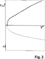
【0025】
車輪ブレーキ内に発生するブレーキ圧力PRad と、ブレーキペダルの操作変位Sが、図2において、ペダル力Fに依存して示してある。ブレーキ圧力PRad は第1の液圧室3から押しのけられた容積と、車輪ブレーキ8,9,10,11自体の圧力媒体容積受入れ特性曲線に依存する。ペダル力とペダル変位の特性曲線はばね6の特性曲線によって決まる。従って、ペダル力とペダル変位の特性曲線は、ばね特性曲線によっておよびブレーキ装置の設計とモータ17とポンプ16′の制御によるペダル力とブレーキ圧力の特性曲線によって、比較的に広い限度内で調節可能である。
【0026】
次の図3〜8は、図1または先行する各々の図と異なる点についてのみ説明する。
【0027】
図3に示した本発明の他の有利な実施の形態から、双方向ポンプ16′が一方の作動方向を有するポンプ16によって置き換え可能であることが推察可能である。この場合、ポンプ16と逆止弁18に並列に接続された弁21、特にアナログ弁が付加的に配置されている。ポンプ入口側は圧力発生器ユニット2の方に開放する逆止弁22を備えている。第1の管路7内には第1の圧力センサ23が付加的に設けられている。ブレーキ圧力上昇と低下の制御は弁21によって行われる。これは制御技術的な理由からおよび小さな騒音のために、アナログ弁として形成されると有利である。ポンプ16はブレーキング操作中連続的に運転されると有利である。というのは、車輪ブレーキ8,9,10,11への圧力媒体の流量が弁21を介して連続的に制御可能であるからである。ポンプ16は吸込み制御タイプでもよいし、吸込み絞りタイプでもよい。圧力発生器ユニット2の第1の室3から管路7を経て押し出された容積だけが、ポンプ16によって車輪ブレーキ8,9,10,11に搬送される。第1の液圧室3内は本発明に従って、ほぼ常に約0バールの圧力に調節されている。
【0028】
図4は、液圧−機械式位置追跡コントローラがブレーキ圧力発生器ユニット2に付設されている点が図3と異なっている。この位置追従コントローラは第2の液圧室24を備えている。この第2の液圧室内には追従ピストン25が設けられている。追従ピストン25には調節棒27が付設されている。追従弁26が設けられているこの調節棒は第1のピストン4に作用連結され、その位置はばね6の変形によって変化する。車輪ブレーキ8,9,10,11の方に向いたポンプ出口側の第3の液圧管路7′は第1の液圧ピストン室28に案内されている。この第1の液圧ピストン室は追従ピストン25によって第2の液圧室24から分離されている。第2の液圧室24から第4の液圧管路29が車輪ブレーキ8,9,10,11まで案内されている。ブレーキング操作時に、前述の実施の形態と同様に、圧力媒体はばね6を備えた第1の室3から管路7を経てポンプ16に供給され、圧力を高めて第3の管路7′を経て第1のピストン室28に案内される。第2の液圧室24から押し出された圧力媒体容積によって、圧力が管路29を経て車輪ブレーキ8,9,10,11を付勢する。圧力の制御はここでは、追従弁26によって行われる。この追従弁はポンプによって発生した圧力に相応して、調節棒27によって開放される。それによって、所定の量の圧力媒体が第5の液圧管路30を経て圧力媒体補給容器20に戻され、それによって追従ピストン25と第4の管路29を経て車輪ブレーキ8,9,10,11に加えられる圧力が制御される。ポンプ16は更に、逆止弁32と絞り33を接続配置した第6の液圧管路31と、第7の液圧管路34を介して、圧力媒体補給容器20に接続されている。それによって、漏洩流、例えば第1のピストン室28内の圧力媒体の損失を生じる追従ピストン26の漏洩流を補償することができる。圧力低下はここでは、追従ピストン25内の中央弁35と圧力媒体補給容器20までの管路30とを介して可能である。
【0029】
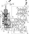
図5に示した本発明の実施の形態の場合には、ブレーキ圧力発生器ユニット2がブレーキペダルによって操作可能なタンデム式マスターシリンダ36を備えている。このタンデム式マスターシリンダは第1のマスターシリンダピストン37と第2のマスターシリンダピストン38によって互いに分離された2つの圧力室と、第1のマスターシリンダ室39と、第2のマスターシリンダ室40とを備えている。マスターシリンダピストン37,38はそれぞれ中央弁41,42を備えている。このようなタンデム式マスターシリンダ36の作用は本文脈において詳細に説明しない。なぜなら、この作用は関連する専門分野で働いている専門家に充分に知られているからである。タンデム式マスターシリンダ36の両ブレーキ回路で発生した圧力による車輪ブレーキ8,9,10,11の直接的な付勢は、ここでは緊急状況で、すなわちポンプ16またはモータ17の故障の場合に行われる。第8の管路43を介して第1のマスターシリンダ圧力室39が第2の液圧ピストン室44に接続されている。この第2の液圧ピストン室は中央弁65を備えた分離ピストン64によって、第1の液圧室3に対して分離されている。この第1の液圧室内には、弾性的な手段6が配置されている。分離ピストン64によって、第3のブレーキ回路からの2つのタンデム式マスターブレーキシリンダ回路の液圧的な分離が行われている。この第3のブレーキ回路の場合、第1の液圧室3がポンプ16によってエネルギー供給部に接続され、好ましくは中央弁65を介して圧力媒体補給容器20の接続部に接続され、そして好ましくは通電しないときに開放する弁47,48を介して後輪ブレーキ10,11に接続され、そして好ましくは通電しないときに閉じる弁45,46を介して車両の前輪ブレーキ8,9に接続可能である。図5には、ブレーキ圧力のABSコントロール/TCSコントロールを可能にする弁が示してある。そのために、第2の管路7に接続する管路部分7a,7b,7c,7dに挿置され個々の車輪ブレーキ8,9,10,11に通じる入口弁45,46,47,48と、車輪ブレーキ8,9,10,11から離れる第9の管路49の管路部分49a,49b,49c,49d内に配置された出口弁50,51,52,53が役立つ。第1のマスターシリンダ39と第2のマスターシリンダ40の圧力室から、第10と第11の液圧管路54,55が車輪ブレーキ8,9に案内されている。この液圧管路は弁56,57によって遮断可能である。
【0030】
通常のブレーキングの場合には、圧力媒体は第1のマスターシリンダ室39から第2の液圧ピストン室44に達し、分離ピストン64がばね6の抵抗に抗して動かされる。分離ピストン64の運動に相応して、圧力媒体が第1の液圧室3から押し出され、管路7、ポンプ16およびそれに接続する管路7a,7b,7c,7dを経て車輪ブレーキ8,9,10,11に供給される。そのとき、入口弁45,46,47,48は開放している。ABSコントロール介入なしの通常のブレーキングの場合には、出口弁50,51,52,53は閉じている。この弁の制御はABS,TCSおよびESPのような電子式ブレーキコントロールシステムの公知の方法に従って行われる。第2の管路19内のブレーキ圧力は第2の圧力センサ63によって測定される。すべての弁とモータ17の制御は、ブレーキペダル1に設けた変位センサ62によって検出された運転者ブレーキング要求に対応しておよび第2の圧力センサ63によって実際に測定された圧力に依存して行われる。この場合、変位センサ信号によって、良好な“二段反応装置機能(シュプリンガー機能)”を示すことができる。これは、システムの所定の変位−圧力−特性曲線が調節され、それによって運転者にとってブレーキ作用の制御可能性がブレーキ圧力の下側範囲において改善されることを意味する。弁47,48と56,57は図示のように、通電しない状態で開放され、ポンプ16またはモータ17による液圧上昇の停止の場合に緊急ブレーキング機能を保証する。ブレーキ圧力はペダル1を操作することによって、一方では第1と第2のマスターシリンダ39,40の圧力室から管路54,55を経て車輪ブレーキ8,9に案内され、他方では第1の圧力室3から管路7を経て車輪ブレーキ10,11に案内される。それによって、システムの故障時には、4個すべての車輪ブレーキ8,9,10,11が圧力源としての運転者踏力によって付勢可能である。ポンプによるエネルギー供給停止の場合、液圧回路の分離によって、前車軸の車輪ブレーキを付勢するために運転者によって行われるストローク作業全体が、タンデム式マスターブレーキシリンダの回路を介して可能となり、そして後車軸の車輪ブレーキについては第3のブレーキ回路を介して可能となる。それによって、第3のブレーキ回路の故障時に、後車軸だけが影響を及ぼされ、他のブレーキ回路(タンデム式マスターブレーキシリンダ回路)の故障は前車軸車輪ブレーキの停止だけを生じる。
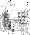
【0031】
図6には、図5に対応する構造が示してある。この構造の場合には、第1の液圧室3の分離ピストン64が中央弁5を備えている。更に、管路7には、脈動減衰のための減衰室58が統合され、そして弁21に対して並列に、第1の液圧室の方に開放する圧力制限弁59が配置されている。それによって、車輪ブレーキ8,9,10,11に作用する圧力の迅速および確実な低下が出口弁50,51,52,53を介して達成される。この実施の形態によって、要求に応じてゆっくりしたまたは迅速な圧力上昇または圧力低下が確実に保証される。この場合同時に、操作装置1のきわめて効果的な脈動緩和が達成される。更に、車両の1本の車軸の車輪ブレーキの均一な負荷と、不均一なブレーキ圧力分布による“ゆがみ”が回避される。
【0032】
本発明によるブレーキ装置を実現するために、通常の場合、単一回路の1個のポンプ16と、全部で3個の制御弁21,50,51と、8個の切換え弁45,46,47,48,52,53,56,57だけしか必要としない。このようなブレーキ装置は基本的にはABS,TCS,ESP,HBA(液圧ブレーキアシスタント)またはACC(オートマチッククルーズコントロール)のようなすべての電子式ブレーキコントロールシステムのために適している。システムの故障時に、4個のすべての車輪ブレーキ8,9,10,11が運転者の力によって操作可能である。電子式ブレーキコントロールシステム、例えばABSの制御相における圧力低下は0バールまで可能である。TCSによる制御介入は、運転者による操作と切り離して行うことができる。ESPコントロールの場合、大きな横断面を有する、圧力媒体補給容器20に対する液圧接続部によって、圧力媒体を迅速に吸い込むことができ、それによって車輪ブレーキ内の高いブレーキ圧力の迅速な上昇が実現可能である。
【0033】
図7,8は、弁21が省略され、その機能が液圧−機械式に制御される弁60によって置き換えられている本発明の2つの実施の形態を形態を示している。図8に示したブレーキ装置の場合には、遮断弁61が付加的に設けられている。それによって、TCSまたはESPのようなブレーキ制御システムによるアクティブブレーキングのために、電子式ブレーキ制御システムによる独立制御への切換えが達成可能である。
【図面の簡単な説明】
【図1】 弾性的な手段を備えた第1の液圧室と可逆ポンプを備えた本発明によるブレーキ装置の実施の形態を示す図である。
【図2】 ペダル力Fに依存して車輪ブレーキ内のブレーキ圧力PRad とブレーキペダルの操作変位Sを示す図である。
【図3】 ポンプに対して並列に接続された弁を備えた本発明によるブレーキ装置の実施の形態を示す図である。
【図4】 液圧−機械式位置追従コントローラを備えた変形を示す図である。
【図5】 ブレーキ圧力発生器ユニットがタンデム式マスターシリンダを備えている、本発明によるブレーキ装置の実施の形態を示す図である。
【図6】 第1の液圧室のピストンが中央弁を備えている、図5の実施の形態の変形を示す図である。
【図7】 アナログ弁が液圧−機械式弁によって置き換えられている、タンデム式マスターシリンダを備えた実施の形態を示す図である。
【図8】 付加的な分離弁を備えた、図6に示した実施の形態の変形を示す図である。
【符号の説明】
1 操作ペダル
2 ブレーキ圧力発生器ユニット
3 第1の液圧室
4 第1のピストン
5 中央弁
6 ばね
7 第1の液圧管路
7′ 第3の液圧管路
8 第1の車輪ブレーキ
9 第2の車輪ブレーキ
10 第3の車輪ブレーキ
11 第4の車輪ブレーキ
12 第1の車輪回転数センサ
13 第2の車輪回転数センサ
14 第1の車輪回転数センサ
15 第2の車輪回転数センサ
16 ポンプ
16′ 双方向ポンプ
17 モータ
18 逆止弁
19 第2の液圧管路
20 圧力媒体補給容器
21 弁
22 逆止弁
23 第1の圧力センサ
24 第2の液圧室
25 追従ピストン
26 追従弁
27 調節棒
28 第1の液圧ピストン室
29 第4の液圧管路
30 第5の液圧管路
31 第6の液圧管路
32 逆止弁
33 絞り
34 第7の液圧管路
35 中央弁
36 タンデム式マスターブレーキシリンダ
37 第1のマスターシリンダピストン
38 第2のマスターシリンダピストン
39 第1のマスターシリンダ室
40 第2のマスターシリンダ室
41 中央弁
42 中央弁
43 第8の液圧管路
44 第2の液圧ピストン室
45 入口弁
46 入口弁
47 入口弁
48 入口弁
49 第9の液圧管路
50 出口弁
51 出口弁
52 出口弁
53 出口弁
54 第10の液圧管路
55 第11の液圧管路
56 分離弁
57 分離弁
58 減衰室
59 圧力制限弁
60 液圧−機械式制御弁
61 遮断弁
62 変位センサ
63 第2の圧力センサ
64 分離ピストン
65 中央弁[0001]
In the present invention, the brake pressure generator unit can be operated by applying an operating force via an operating device, and the brake pressure generator unit includes a first hydraulic pressure chamber, and the volume of the hydraulic pressure chamber is the brake pressure. The pressure medium is reduced during operation of the generator unit, the pressure medium is pushed away from the brake pressure generator unit based on the volume reduction, and the wheel brake is connected to the brake pressure generator unit by the first hydraulic connection, The present invention relates to a hydraulic brake device for a vehicle in which a pump is disposed in a hydraulic pressure connection portion, and by this pump, a pressure medium pushed away from a first hydraulic pressure chamber based on volume reduction can be conveyed to a wheel brake.
[0002]
In this technology, hydraulic brake devices equipped with a hydraulic booster are becoming increasingly important. This is particularly true for automotive boosters where the booster to be incorporated should be as compact as possible. Furthermore, vacuum boosters that have been used in the past can no longer be used effectively. This is because the vacuum booster requires a lot of space, and the latest vehicles no longer provide the necessary vacuum for boosting.
[0003]
However, known hydraulic boosters are relatively costly and are relatively uncontrollable or cause a large reaction to the operating device, for example a brake pedal, resulting in a pedal sensation that is uncomfortable for the driver. .
[0004]
An object of the present invention is to overcome the drawbacks of such a brake device and reduce the reaction of an increase or decrease in hydraulic pressure on the operating device.
[0005]
This problem is solved by a combination of features described in the characterizing portion of
[0006]
In principle, the present invention has a pump disposed in a first hydraulic connection between the first hydraulic chamber of the brake pressure generator unit and the wheel brake, and this pump is connected to the operating force of the operating device. When the pressure medium displaced from the first hydraulic chamber at the time of introduction is transferred to the wheel brake and, in turn, a brake pedal is used as the operating device to reproduce the conventional volume-pressure-characteristic curve of the wheel brake. In order to generate a force-displacement-characteristic curve or force-stroke-characteristic curve that gives a comfortable and comfortable pedal feel, an elastic means is arranged in the first hydraulic pressure chamber.
[0007]
By conveying the volume displaced from the first hydraulic chamber of the brake pressure generator unit, the pump creates a pressure difference between the first hydraulic chamber and the wheel brake. It is advantageous if the pressure in the first hydraulic chamber is adjusted to a pressure close to 0 bar by means of a pump that transports substantially continuously. Thereby, the driver substantially manages only the action of the elastic means. The reaction of the brake pressure generated in the wheel brake to the operating device, in particular the pedal reaction, is greatly reduced.
[0008]
Another advantage is the technically relatively simple structure of the braking device. Basically, only a pump for applying brake pressure to the wheel brake is required. Furthermore, the pump is prefilled by the displacement of the pressure medium from the first hydraulic chamber by the operating force of the driver. This is the premise for reliable function at low temperatures as well as significant improvements in braking. In the case of the brake device according to the invention, no additional accumulator is required, so that the system is technically simple and thus inexpensive.
[0009]
Furthermore, there is basically no direct relationship between the force-stroke-characteristic curve and the volume-pressure-characteristic curve of the operating device. This is because force and pressure or volume and displacement can in principle be adjusted independently of each other. The boosting characteristic of the brake device can basically be formed almost arbitrarily.
[0010]
In the present invention, a positive displacement pump, particularly a positive displacement pump that operates continuously is used as the pump. In doing so, the inlet pressure is increased by the connected motor until the pump outlet pressure matches the increased desired pressure. In such a pump, it is particularly advantageous if a quiet pressure rise with small pulsations is achieved. In this case, it is advantageous if the boost characteristics can be freely selected by the design and control of the pump. There is no large change in direction of the medium in the entire control circuit. This is because the brake pressure generator unit and the wheel brake operating circuit operate hydraulically. Particularly suitable continuously conveying positive displacement pumps are gear pumps, vane pumps and spindle pumps, in particular internal gear pumps.
[0011]
The pump is advantageously driven by a motor, in particular a brushless permanent excitation DC motor. The DC motor is also capable of idling when no brake pressure is required, so that it is generally unnecessary to start the motor when brake pressure is required.
[0012]
According to the invention, the pump may be a pump with controlled suction or a pump with throttled suction. In the case of a suction control type / suction throttle type pump, the pressure generated by the pump is controlled by the pressure medium flow rate supplied to the suction side of the pump. Such a control method of the pump can be realized relatively easily as compared with the clock control, and can be controlled well. The pump suction control has the advantage that energy is optimally used. This is because the pump is loaded only to the extent necessary for the pressure increase.
[0013]
In accordance with the present invention, the pump can be formed as a bi-directional transport pump or a reversible pump. Thereby, a pressure increase towards the wheel brake and a pressure decrease reaching the wheel brake can be actively performed by the pump.
[0014]
In the present invention, the second hydraulic pressure connecting portion is disposed between the first hydraulic pressure chamber and the wheel brake. A valve, in particular a control valve, is arranged at the second hydraulic connection. With this valve, the flow rate of the pressure medium conveyed by the pump can be adjusted. By this means, the desired brake pressure can be adjusted technically relatively easily and at low cost. In this case, it is particularly advantageous if the control valve can be controlled in an analog manner. Thereby, a relatively simple structure of the brake device according to the invention is achieved. The pressure is on the one hand very well controllable, on the other hand the analog valve noise is relatively low.
[0015]
In the present invention, a check valve is provided, and this check valve can be operated by a pressure difference between the first hydraulic pressure chamber and the wheel brake, and an overpressure is generated in the first hydraulic pressure chamber. The second hydraulic connection is opened. Thereby, the volume displaced by the driver during rapid braking operation is transferred from the first hydraulic chamber directly, i.e. by the pump, to the wheel brake. Thereby, a rapid braking action is ensured in the phase where the pump contributes little to little by inertia effects.
[0016]
In the present invention, the control valve is formed as a part of the hydraulic-mechanical position following controller, and the valve position of the hydraulic-mechanical position following controller can be changed based on the deformation of the elastic means. Thereby, pressure control can be advantageously performed without electronically controlling the valve.
[0017]
A third hydraulic pressure connecting portion is provided between the first hydraulic pressure chamber and the pressure medium supply container, and a second valve is disposed in the third hydraulic pressure connecting portion. As a result, when the volume displaced from the first hydraulic chamber is smaller than the volume required for a predetermined desired brake pressure, replenishment suction of brake fluid from the pressure medium replenishment container is possible. There is an advantage of being.
[0018]
In the present invention, the brake pressure generator unit includes a master brake cylinder having at least one hydraulic pressure chamber (master brake cylinder chamber), in particular, a tandem master brake cylinder having two hydraulic pressure master brake cylinder chambers. A brake cylinder chamber is connected to the second piston chamber via a hydraulic line, in which the first hydraulic piston is formed as a separation piston, in particular a separation piston with a central valve, whereby the first The elastic means arranged in the hydraulic chamber can be pressure-biased. The separation piston provides a hydraulic separation of the tandem master brake cylinder circuit from the third brake circuit. In this third brake circuit, the first hydraulic pressure chamber is connected to the energy supply portion by a pump, and in particular connected to the connection portion of the pressure medium supply container via the central valve, and is opened when not particularly energized. It can be connected to the vehicle's rear wheel brake via a valve and can be connected to the vehicle's front wheel brake via a valve that closes when not energized. In this separation, when the brake device breaks down, that is, when the current supply unit fails, the entire stroke operation of the driver is applied to the front axle wheel brake via the tandem master brake cylinder circuit and the third brake circuit. There is an advantage that it can be distributed to the urging of the rear axle wheel brake. When the third brake circuit fails, only the rear axle brake is stopped, and when the other brake circuit fails, only the front axle wheel brake is stopped. This has the advantage that a high availability of the braking device arises.
[0019]
In an advantageous embodiment of the invention, at least one master brake cylinder chamber, in particular two master brake cylinder chambers of a tandem master brake cylinder, provide at least one hydraulic line, in particular two hydraulic lines. In particular, it is connected to the two wheel brakes on the front side, an electronically controllable valve is inserted in this hydraulic pressure line, and an electronically controllable valve is provided between the first hydraulic pressure chamber and the wheel brake And an electronically controllable valve is arranged between the ninth hydraulic line for returning the pressure medium from the wheel brake. As a result, the brake pressure can be controlled very well.
[0020]
In the present invention, at least one master brake cylinder chamber, in particular two master brake cylinder chambers of a tandem master brake cylinder, are connected to the front side via at least one hydraulic line, in particular two hydraulic lines. In this hydraulic pressure line, a separation valve, in particular, one separation valve that can be electromagnetically operated and opened when not energized, is inserted and provided with an elastic means. The first hydraulic chamber is connected to the two wheel brakes, particularly on the rear side, via a pipe line and a pipe line part connected to this pipe line. One separation valve that opens when not energized is inserted, and the first hydraulic chamber provided with elastic means is connected via a pipe line and a pipe line part connected to this pipe line, in particular. This tube can be connected to the front two wheel brakes. In part, the separation valve, in particular solenoid-operated possible for one each closed when not energized separation valve is interposed. Thereby, the brake pressure can be controlled very well for each individual wheel.
[0021]
In the present invention, a fourth hydraulic line is arranged, which can be shut off via a separation valve, in particular a valve that can be electromagnetically operated and closed when not energized, and in particular from the wheel brake in the switching position. The back flow of the pressure medium to the pressure medium replenishing container is enabled through the master brake cylinder chamber. Thereby, the pressure drop can be performed quickly and reliably.
[0022]
Next, the present invention will be described in detail with reference to the accompanying drawings (FIGS. 1 to 8).
[0023]
The brake device shown in FIG. 1 substantially comprises a brake pressure generator unit 2 that can be operated by an
[0024]
When the
[0025]
Brake pressure P generated in the wheel brakeRad The operation displacement S of the brake pedal is shown depending on the pedal force F in FIG. Brake pressure PRad Depends on the volume displaced from the first
[0026]
The following FIGS. 3-8 will only describe the differences from FIG. 1 or each preceding figure.
[0027]
From the other advantageous embodiment of the invention shown in FIG. 3, it can be inferred that the bidirectional pump 16 'can be replaced by a
[0028]
FIG. 4 differs from FIG. 3 in that a hydraulic-mechanical position tracking controller is attached to the brake pressure generator unit 2. This position tracking controller includes a second
[0029]
In the case of the embodiment of the present invention shown in FIG. 5, the brake pressure generator unit 2 includes a
[0030]
In the case of normal braking, the pressure medium reaches the second
[0031]
FIG. 6 shows a structure corresponding to FIG. In the case of this structure, the
[0032]
In order to realize the brake device according to the invention, in the normal case, one
[0033]
Figures 7 and 8 show two embodiments of the present invention in which the
[Brief description of the drawings]
FIG. 1 is a view showing an embodiment of a brake device according to the present invention including a first hydraulic chamber provided with elastic means and a reversible pump.
FIG. 2 Brake pressure P in the wheel brake depending on the pedal force FRad FIG. 6 is a diagram illustrating an operation displacement S of a brake pedal.
FIG. 3 shows an embodiment of a brake device according to the invention with a valve connected in parallel to the pump.
FIG. 4 is a diagram showing a modification provided with a hydraulic-mechanical position following controller.
FIG. 5 shows an embodiment of a brake device according to the invention, in which the brake pressure generator unit comprises a tandem master cylinder.
6 shows a variation of the embodiment of FIG. 5 in which the piston of the first hydraulic chamber has a central valve.
FIG. 7 shows an embodiment with a tandem master cylinder in which the analog valve is replaced by a hydraulic-mechanical valve.
FIG. 8 shows a variation of the embodiment shown in FIG. 6 with an additional separation valve.
[Explanation of symbols]
1 Operation pedal
2 Brake pressure generator unit
3 First hydraulic chamber
4 First piston
5 Central valve
6 Spring
7 First hydraulic line
7 'Third hydraulic line
8 First wheel brake
9 Second wheel brake
10 Third wheel brake
11 Fourth wheel brake
12 First wheel rotational speed sensor
13 Second wheel speed sensor
14 First wheel speed sensor
15 Second wheel speed sensor
16 pump
16 'bidirectional pump
17 Motor
18 Check valve
19 Second hydraulic line
20 Pressure medium supply container
21 Valve
22 Check valve
23 First pressure sensor
24 Second hydraulic chamber
25 following piston
26 Follow-up valve
27 Adjustment rod
28 First hydraulic piston chamber
29 Fourth hydraulic line
30 Fifth hydraulic line
31 Sixth hydraulic line
32 Check valve
33 Aperture
34 Seventh hydraulic line
35 Central valve
36 Tandem Master Brake Cylinder
37 First master cylinder piston
38 Second master cylinder piston
39 First master cylinder chamber
40 Second master cylinder chamber
41 Central valve
42 Central valve
43 Eight hydraulic lines
44 Second hydraulic piston chamber
45 Inlet valve
46 Inlet valve
47 Inlet valve
48 Inlet valve
49 Ninth hydraulic line
50 outlet valve
51 Outlet valve
52 Outlet valve
53 Outlet valve
54 Tenth hydraulic line
55 Eleventh hydraulic line
56 Separation valve
57 Separation valve
58 Damping chamber
59 Pressure limit valve
60 Hydraulic-mechanical control valve
61 Shut-off valve
62 Displacement sensor
63 Second pressure sensor
64 separation piston
65 Central valve
Claims (8)
第1の液圧室(3)が弾性的な手段(6)を備え、操作装置(1)の操作力を加える際に前記の弾性的な手段によって、力−変位−特性曲線に影響が与えられ、
ブレーキ圧力発生器ユニット(2)が少なくとも1個の液圧室(マスターブレーキシリンダ室)を有するマスターブレーキシリンダ(36)を備え、マスターブレーキシリンダ室(39)が液圧管路(43)を介して第2のピストン室(44)に接続され、このピストン室内で、第1の液圧室(3)内に配置された弾性的な手段(6)が、分離ピストン(64)によって圧力付勢可能であり、
少なくとも1個のマスターブレーキシリンダ(36)のマスターブレーキシリンダ室(39,40)が、少なくとも1個の液圧管路(54,55)を介して、前側の2個の車輪ブレーキ(8,9)に接続され、この液圧管路内に電子制御可能な弁(56,57)が挿置されていることと、第1の液圧室(3)と車輪ブレーキ(8,9,10,11)の間に電子制御可能な弁(45,46,47,48)が設けられていることと、電子制御可能な弁(50,51,52,53)が車輪ブレーキ(8,9,10,11)から圧力媒体を戻すための第9の液圧管路(49)の間に配置されている
ことを特徴とするブレーキ装置。The brake pressure generator unit (2) can be operated by applying an operating force via the operating device (1), and the brake pressure generator unit includes a first hydraulic pressure chamber (3), and this hydraulic pressure chamber Is reduced when the brake pressure generator unit (2) is operated, the pressure medium is pushed away from the brake pressure generator unit based on the volume reduction, and the wheel brakes (8, 9, 10, 11) are moved to the first liquid. A pressure connection (7) is connected to the brake pressure generator unit, and a pump (16, 16 ') is arranged in this first hydraulic connection, by means of this pump, the first hydraulic pressure based on the volume reduction In the vehicle hydraulic brake device, the pressure medium pushed away from the chamber can be conveyed to the wheel brakes (8, 9, 10, 11).
The first hydraulic chamber (3) includes an elastic means (6), and when the operating force of the operating device (1) is applied, the elastic means influences the force-displacement-characteristic curve. And
The brake pressure generator unit (2) includes a master brake cylinder (36) having at least one hydraulic pressure chamber (master brake cylinder chamber), and the master brake cylinder chamber (39) is connected via a hydraulic pressure line (43). An elastic means (6) connected to the second piston chamber (44) and arranged in the first hydraulic chamber (3) can be pressure-biased by the separating piston (64). And
At least one master brake cylinder (36) of the master brake cylinder chamber (39, 40), via at least one hydraulic line of (54, 55), the front side of the two wheel brakes (8, 9 ), An electronically controllable valve (56, 57) is inserted in the hydraulic line, a first hydraulic chamber (3) and a wheel brake (8, 9, 10, 11). ) Are provided with electronically controllable valves (45, 46, 47, 48) and electronically controllable valves (50, 51, 52, 53) are wheel brakes (8, 9, 10, Brake device characterized in that it is arranged between the ninth hydraulic line (49) for returning the pressure medium from 11).
Applications Claiming Priority (7)
| Application Number | Priority Date | Filing Date | Title |
|---|---|---|---|
| DE19934808.1 | 1999-07-28 | ||
| DE19934808 | 1999-07-28 | ||
| DE19934802.2 | 1999-07-28 | ||
| DE19934807.3 | 1999-07-28 | ||
| DE19934802 | 1999-07-28 | ||
| DE19934807 | 1999-07-28 | ||
| PCT/EP2000/007233 WO2001007307A1 (en) | 1999-07-28 | 2000-07-27 | Hydraulic brake system |
Publications (3)
| Publication Number | Publication Date |
|---|---|
| JP2003505294A JP2003505294A (en) | 2003-02-12 |
| JP2003505294A5 JP2003505294A5 (en) | 2007-08-30 |
| JP4852207B2 true JP4852207B2 (en) | 2012-01-11 |
Family
ID=27219240
Family Applications (1)
| Application Number | Title | Priority Date | Filing Date |
|---|---|---|---|
| JP2001512412A Expired - Fee Related JP4852207B2 (en) | 1999-07-28 | 2000-07-27 | Hydraulic brake device |
Country Status (5)
| Country | Link |
|---|---|
| US (2) | US6851763B1 (en) |
| EP (1) | EP1204547B1 (en) |
| JP (1) | JP4852207B2 (en) |
| DE (1) | DE50012931D1 (en) |
| WO (1) | WO2001007307A1 (en) |
Families Citing this family (19)
| Publication number | Priority date | Publication date | Assignee | Title |
|---|---|---|---|---|
| EP1204547B1 (en) * | 1999-07-28 | 2006-06-07 | Continental Teves AG & Co. oHG | Hydraulic brake system |
| DE10159788B4 (en) * | 2001-12-05 | 2004-03-04 | Daimlerchrysler Ag | Pedal path simulator with brake fluid return and tandem master cylinder for an electrohydraulic brake system |
| EP1470979B1 (en) * | 2003-04-24 | 2006-12-27 | Nissan Motor Company Limited | Vehicle brake system |
| DE102004041449B3 (en) * | 2004-08-27 | 2006-03-09 | Keiper Gmbh & Co.Kg | Fitting for a vehicle seat, in particular for a motor vehicle seat |
| DE102004050059A1 (en) * | 2004-10-14 | 2006-04-27 | Robert Bosch Gmbh | Method and device for releasing a brake assist function in a motor vehicle |
| US20080265665A1 (en) * | 2005-02-18 | 2008-10-30 | Continental Teves Ag & Co. Ohg | Brake System for Motor Vehicles |
| US7354119B2 (en) | 2005-09-27 | 2008-04-08 | Joel Nazara | Brake system |
| DE102007036859A1 (en) | 2006-08-10 | 2008-04-30 | Continental Teves Ag & Co. Ohg | Externally controllable electrohydraulic vehicle brake system |
| US20080116742A1 (en) * | 2006-11-20 | 2008-05-22 | Lipski Mark C | Brake modulation device and method |
| DE102007019929A1 (en) * | 2007-04-27 | 2008-11-06 | Continental Teves Ag & Co. Ohg | Correction method for correcting drive characteristics for analogized hydraulic valves in motor vehicle brake systems |
| DE102009009647A1 (en) * | 2009-02-19 | 2010-08-26 | Lucas Automotive Gmbh | Braking unit for a land vehicle with regenerative braking functionality |
| CN102421644B (en) * | 2010-02-02 | 2014-11-19 | 丰田自动车株式会社 | Brake system |
| JP2013129362A (en) * | 2011-12-22 | 2013-07-04 | Hitachi Automotive Systems Ltd | Brake control device |
| GB2552803B (en) * | 2016-08-10 | 2021-12-15 | Arrival Ltd | A braking control system |
| US10363912B2 (en) | 2017-03-09 | 2019-07-30 | Ford Global Technologies, Llc | Hydraulic brake actuators and related methods |
| DE102017221716A1 (en) | 2017-12-01 | 2019-06-06 | Continental Teves Ag & Co. Ohg | Brake system for motor vehicles and method for operating a brake system |
| CN111511617B (en) * | 2017-12-27 | 2023-01-06 | 罗伯特·博世有限公司 | Real-time pressure-volume curve generation for hydraulic systems |
| KR20210128676A (en) * | 2020-04-17 | 2021-10-27 | 현대모비스 주식회사 | ElectricoHhydraulic Brake |
| CN115853931B (en) * | 2023-03-03 | 2023-05-09 | 太原矿机电气股份有限公司 | Speed limiting braking control system with adjustable speed limiting value |
Citations (8)
| Publication number | Priority date | Publication date | Assignee | Title |
|---|---|---|---|---|
| JPH05147524A (en) * | 1991-11-27 | 1993-06-15 | Toyota Motor Corp | Brake hydraulic pressure control device |
| JPH07196030A (en) * | 1993-12-18 | 1995-08-01 | Robert Bosch Gmbh | Hydraulic brake device for use in street operating vehicle |
| WO1997021573A1 (en) * | 1995-12-14 | 1997-06-19 | Robert Bosch Gmbh | Hydraulic braking system for road vehicles, in particular passenger cars |
| WO1997023373A1 (en) * | 1995-12-22 | 1997-07-03 | Robert Bosch Gmbh | Process and device for controlling a pump in an electro-hydraulic brake system |
| JPH09240455A (en) * | 1995-12-26 | 1997-09-16 | Denso Corp | Brake device for vehicle |
| JPH09290731A (en) * | 1996-04-25 | 1997-11-11 | Denso Corp | Brake device for vehicle |
| JPH10203337A (en) * | 1997-01-20 | 1998-08-04 | Unisia Jecs Corp | Brake device |
| JPH1170871A (en) * | 1997-07-08 | 1999-03-16 | Robert Bosch Gmbh | Method and device for controlling brake device |
Family Cites Families (11)
| Publication number | Priority date | Publication date | Assignee | Title |
|---|---|---|---|---|
| DE3511533A1 (en) * | 1985-03-29 | 1986-10-09 | Alfred Teves Gmbh, 6000 Frankfurt | BRAKE SYSTEM FOR MOTOR VEHICLES |
| DE3903532A1 (en) * | 1988-02-18 | 1989-08-31 | Volkswagen Ag | Hydraulic motor-vehicle brake system with an anti-lock control device |
| DE3909167A1 (en) * | 1989-03-21 | 1990-09-27 | Bosch Gmbh Robert | DEVICE FOR ANTI-BLOCKING PROTECTION AND DRIVE SLIP LIMIT |
| DE3922947A1 (en) * | 1989-07-12 | 1991-01-17 | Bosch Gmbh Robert | HYDRAULIC VEHICLE BRAKE SYSTEM |
| JPH06191386A (en) * | 1992-09-14 | 1994-07-12 | Aisin Seiki Co Ltd | Anti-lock brake control method and anti-lock brake control device |
| DE4415438A1 (en) * | 1994-05-03 | 1995-11-09 | Teves Gmbh Alfred | Electronically controllable brake actuation system |
| DE19542657C2 (en) | 1995-11-15 | 2001-06-21 | Lucas Ind Plc | Vehicle brake actuation unit |
| DE19643343A1 (en) * | 1996-10-21 | 1998-04-23 | Bosch Gmbh Robert | Slip-controlled hydraulic vehicle brake system |
| US6113197A (en) * | 1996-11-18 | 2000-09-05 | Unisia Jecs Corporation | Wheel braking system |
| DE19716404C1 (en) * | 1997-04-18 | 1998-10-29 | Lucas Automotive Gmbh | Hydraulic brake system for motor vehicles |
| EP1204547B1 (en) * | 1999-07-28 | 2006-06-07 | Continental Teves AG & Co. oHG | Hydraulic brake system |
-
2000
- 2000-07-27 EP EP00956313A patent/EP1204547B1/en not_active Expired - Lifetime
- 2000-07-27 DE DE50012931T patent/DE50012931D1/en not_active Expired - Lifetime
- 2000-07-27 US US10/031,981 patent/US6851763B1/en not_active Expired - Fee Related
- 2000-07-27 WO PCT/EP2000/007233 patent/WO2001007307A1/en active IP Right Grant
- 2000-07-27 JP JP2001512412A patent/JP4852207B2/en not_active Expired - Fee Related
-
2005
- 2005-01-28 US US11/045,876 patent/US20050151416A1/en not_active Abandoned
Patent Citations (8)
| Publication number | Priority date | Publication date | Assignee | Title |
|---|---|---|---|---|
| JPH05147524A (en) * | 1991-11-27 | 1993-06-15 | Toyota Motor Corp | Brake hydraulic pressure control device |
| JPH07196030A (en) * | 1993-12-18 | 1995-08-01 | Robert Bosch Gmbh | Hydraulic brake device for use in street operating vehicle |
| WO1997021573A1 (en) * | 1995-12-14 | 1997-06-19 | Robert Bosch Gmbh | Hydraulic braking system for road vehicles, in particular passenger cars |
| WO1997023373A1 (en) * | 1995-12-22 | 1997-07-03 | Robert Bosch Gmbh | Process and device for controlling a pump in an electro-hydraulic brake system |
| JPH09240455A (en) * | 1995-12-26 | 1997-09-16 | Denso Corp | Brake device for vehicle |
| JPH09290731A (en) * | 1996-04-25 | 1997-11-11 | Denso Corp | Brake device for vehicle |
| JPH10203337A (en) * | 1997-01-20 | 1998-08-04 | Unisia Jecs Corp | Brake device |
| JPH1170871A (en) * | 1997-07-08 | 1999-03-16 | Robert Bosch Gmbh | Method and device for controlling brake device |
Also Published As
| Publication number | Publication date |
|---|---|
| US6851763B1 (en) | 2005-02-08 |
| US20050151416A1 (en) | 2005-07-14 |
| EP1204547B1 (en) | 2006-06-07 |
| JP2003505294A (en) | 2003-02-12 |
| EP1204547A1 (en) | 2002-05-15 |
| DE50012931D1 (en) | 2006-07-20 |
| WO2001007307A1 (en) | 2001-02-01 |
Similar Documents
| Publication | Publication Date | Title |
|---|---|---|
| JP4852207B2 (en) | Hydraulic brake device | |
| US10000191B2 (en) | Brake system and method for controlling a brake system | |
| US20230211761A1 (en) | Brake system | |
| CN111016855B (en) | Method for operating a regenerative braking system of a vehicle, control device for a regenerative braking system of a vehicle, and regenerative braking system | |
| JP5860800B2 (en) | Brake device | |
| EP1808347B1 (en) | Brake device and controller for the same | |
| CN101037107B (en) | Brake control device for vehicle | |
| US9403518B2 (en) | Brake system for a vehicle and method for operating a brake system of a vehicle | |
| RU2531652C2 (en) | Control over operation of automotive fluid-driven brake system with braking system | |
| JPH1086804A (en) | Hydraulic power type vehicle brake device | |
| US10189454B2 (en) | Brake system | |
| US20060087173A1 (en) | Brake control system | |
| JP2000507188A (en) | Hydraulic vehicle brake system | |
| JP2008056228A (en) | Brake system for hybrid and electric vehicles and control method therefor | |
| JP2001106056A (en) | Brake device | |
| JPS61175159A (en) | Brake system functioning as slip control in combination | |
| JP2015003622A (en) | Brake control device | |
| KR20030065821A (en) | Electronic control brake system for automobile | |
| US7537294B2 (en) | Vehicle braking system with active hydraulic brake force assistance and control method for the same | |
| US20020011362A1 (en) | Braking control device for an electrically-powered vehicle | |
| JPH11301442A (en) | Hydraulic brake device for vehicle | |
| JP7167656B2 (en) | vehicle braking device | |
| JP2001213295A (en) | Vehicular hydraulic braking device | |
| JP2001213294A (en) | Vehicular hydraulic braking device | |
| US6702402B1 (en) | Vehicular braking force control apparatus |
Legal Events
| Date | Code | Title | Description |
|---|---|---|---|
| A521 | Written amendment |
Free format text: JAPANESE INTERMEDIATE CODE: A523 Effective date: 20070703 |
|
| A621 | Written request for application examination |
Free format text: JAPANESE INTERMEDIATE CODE: A621 Effective date: 20070703 |
|
| RD04 | Notification of resignation of power of attorney |
Free format text: JAPANESE INTERMEDIATE CODE: A7424 Effective date: 20100519 |
|
| A977 | Report on retrieval |
Free format text: JAPANESE INTERMEDIATE CODE: A971007 Effective date: 20100528 |
|
| A131 | Notification of reasons for refusal |
Free format text: JAPANESE INTERMEDIATE CODE: A131 Effective date: 20100629 |
|
| A601 | Written request for extension of time |
Free format text: JAPANESE INTERMEDIATE CODE: A601 Effective date: 20100928 |
|
| A602 | Written permission of extension of time |
Free format text: JAPANESE INTERMEDIATE CODE: A602 Effective date: 20101005 |
|
| A521 | Written amendment |
Free format text: JAPANESE INTERMEDIATE CODE: A523 Effective date: 20101217 |
|
| A131 | Notification of reasons for refusal |
Free format text: JAPANESE INTERMEDIATE CODE: A131 Effective date: 20110322 |
|
| A521 | Written amendment |
Free format text: JAPANESE INTERMEDIATE CODE: A523 Effective date: 20110614 |
|
| TRDD | Decision of grant or rejection written | ||
| A01 | Written decision to grant a patent or to grant a registration (utility model) |
Free format text: JAPANESE INTERMEDIATE CODE: A01 Effective date: 20110927 |
|
| A01 | Written decision to grant a patent or to grant a registration (utility model) |
Free format text: JAPANESE INTERMEDIATE CODE: A01 |
|
| A61 | First payment of annual fees (during grant procedure) |
Free format text: JAPANESE INTERMEDIATE CODE: A61 Effective date: 20111024 |
|
| R150 | Certificate of patent or registration of utility model |
Ref document number: 4852207 Country of ref document: JP Free format text: JAPANESE INTERMEDIATE CODE: R150 Free format text: JAPANESE INTERMEDIATE CODE: R150 |
|
| FPAY | Renewal fee payment (event date is renewal date of database) |
Free format text: PAYMENT UNTIL: 20141028 Year of fee payment: 3 |
|
| R250 | Receipt of annual fees |
Free format text: JAPANESE INTERMEDIATE CODE: R250 |
|
| R250 | Receipt of annual fees |
Free format text: JAPANESE INTERMEDIATE CODE: R250 |
|
| R250 | Receipt of annual fees |
Free format text: JAPANESE INTERMEDIATE CODE: R250 |
|
| R250 | Receipt of annual fees |
Free format text: JAPANESE INTERMEDIATE CODE: R250 |
|
| R250 | Receipt of annual fees |
Free format text: JAPANESE INTERMEDIATE CODE: R250 |
|
| LAPS | Cancellation because of no payment of annual fees |