JP4850829B2 - Method for rolling a strip in a roll stand - Google Patents
Method for rolling a strip in a roll stand Download PDFInfo
- Publication number
- JP4850829B2 JP4850829B2 JP2007517118A JP2007517118A JP4850829B2 JP 4850829 B2 JP4850829 B2 JP 4850829B2 JP 2007517118 A JP2007517118 A JP 2007517118A JP 2007517118 A JP2007517118 A JP 2007517118A JP 4850829 B2 JP4850829 B2 JP 4850829B2
- Authority
- JP
- Japan
- Prior art keywords
- work roll
- movement
- strip
- roll
- rolling
- Prior art date
- Legal status (The legal status is an assumption and is not a legal conclusion. Google has not performed a legal analysis and makes no representation as to the accuracy of the status listed.)
- Active
Links
- 238000005096 rolling process Methods 0.000 title claims abstract description 24
- 238000000034 method Methods 0.000 title claims abstract description 21
- 125000004122 cyclic group Chemical group 0.000 claims abstract description 7
- 230000000694 effects Effects 0.000 claims abstract description 3
- 238000013000 roll bending Methods 0.000 claims description 32
- 230000000737 periodic effect Effects 0.000 claims description 22
- 230000008859 change Effects 0.000 claims description 8
- 230000008569 process Effects 0.000 claims description 6
- 238000005498 polishing Methods 0.000 claims description 4
- 230000007246 mechanism Effects 0.000 claims description 2
- 239000013589 supplement Substances 0.000 abstract 1
- 238000005452 bending Methods 0.000 description 6
- 238000011017 operating method Methods 0.000 description 3
- 230000015556 catabolic process Effects 0.000 description 1
- 230000000295 complement effect Effects 0.000 description 1
- 230000001143 conditioned effect Effects 0.000 description 1
- 238000006731 degradation reaction Methods 0.000 description 1
- 230000003993 interaction Effects 0.000 description 1
- 230000008092 positive effect Effects 0.000 description 1
- 230000007704 transition Effects 0.000 description 1
Images


Classifications
-
- B—PERFORMING OPERATIONS; TRANSPORTING
- B21—MECHANICAL METAL-WORKING WITHOUT ESSENTIALLY REMOVING MATERIAL; PUNCHING METAL
- B21B—ROLLING OF METAL
- B21B37/00—Control devices or methods specially adapted for metal-rolling mills or the work produced thereby
- B21B37/28—Control of flatness or profile during rolling of strip, sheets or plates
- B21B37/42—Control of flatness or profile during rolling of strip, sheets or plates using a combination of roll bending and axial shifting of the rolls
-
- B—PERFORMING OPERATIONS; TRANSPORTING
- B21—MECHANICAL METAL-WORKING WITHOUT ESSENTIALLY REMOVING MATERIAL; PUNCHING METAL
- B21B—ROLLING OF METAL
- B21B37/00—Control devices or methods specially adapted for metal-rolling mills or the work produced thereby
- B21B37/28—Control of flatness or profile during rolling of strip, sheets or plates
- B21B37/40—Control of flatness or profile during rolling of strip, sheets or plates using axial shifting of the rolls
-
- B—PERFORMING OPERATIONS; TRANSPORTING
- B21—MECHANICAL METAL-WORKING WITHOUT ESSENTIALLY REMOVING MATERIAL; PUNCHING METAL
- B21B—ROLLING OF METAL
- B21B37/00—Control devices or methods specially adapted for metal-rolling mills or the work produced thereby
- B21B37/28—Control of flatness or profile during rolling of strip, sheets or plates
- B21B37/38—Control of flatness or profile during rolling of strip, sheets or plates using roll bending
-
- B—PERFORMING OPERATIONS; TRANSPORTING
- B21—MECHANICAL METAL-WORKING WITHOUT ESSENTIALLY REMOVING MATERIAL; PUNCHING METAL
- B21B—ROLLING OF METAL
- B21B13/00—Metal-rolling stands, i.e. an assembly composed of a stand frame, rolls, and accessories
- B21B13/14—Metal-rolling stands, i.e. an assembly composed of a stand frame, rolls, and accessories having counter-pressure devices acting on rolls to inhibit deflection of same under load; Back-up rolls
- B21B13/142—Metal-rolling stands, i.e. an assembly composed of a stand frame, rolls, and accessories having counter-pressure devices acting on rolls to inhibit deflection of same under load; Back-up rolls by axially shifting the rolls, e.g. rolls with tapered ends or with a curved contour for continuously-variable crown CVC
-
- B—PERFORMING OPERATIONS; TRANSPORTING
- B21—MECHANICAL METAL-WORKING WITHOUT ESSENTIALLY REMOVING MATERIAL; PUNCHING METAL
- B21B—ROLLING OF METAL
- B21B29/00—Counter-pressure devices acting on rolls to inhibit deflection of same under load, e.g. backing rolls ; Roll bending devices, e.g. hydraulic actuators acting on roll shaft ends
-
- B—PERFORMING OPERATIONS; TRANSPORTING
- B21—MECHANICAL METAL-WORKING WITHOUT ESSENTIALLY REMOVING MATERIAL; PUNCHING METAL
- B21B—ROLLING OF METAL
- B21B31/00—Rolling stand structures; Mounting, adjusting, or interchanging rolls, roll mountings, or stand frames
- B21B31/16—Adjusting or positioning rolls
- B21B31/18—Adjusting or positioning rolls by moving rolls axially
Landscapes
- Engineering & Computer Science (AREA)
- Mechanical Engineering (AREA)
- Control Of Metal Rolling (AREA)
- Metal Rolling (AREA)
- Reduction Rolling/Reduction Stand/Operation Of Reduction Machine (AREA)
- Paper (AREA)
- Chemical Or Physical Treatment Of Fibers (AREA)
- Pretreatment Of Seeds And Plants (AREA)
Abstract
Description
本発明は、その湾曲した輪郭が3次以上の多項式によって表現可能であるCVC研磨面を備えている軸方向に移動可能な2つのワークロールと、2つのバックアップロールと、軸方向に移動可能な2つの中間ロールと、ワークロール曲げシステムと、中間ロール曲げシステムとから成り、この場合、ストリップ平面度及びストリッププロフィルをコントロールするために、調整機構としてワークロール曲げ又はワークロール移動が適用される圧延ラインのロールスタンドにおいてストリップを圧延するための方法に関する。 The present invention has two work rolls that are movable in the axial direction and a two backup rolls that are provided with a CVC polishing surface whose curved contour can be expressed by a third or higher order polynomial, and are movable in the axial direction. Rolling consisting of two intermediate rolls, a work roll bending system and an intermediate roll bending system, in which work roll bending or work roll movement is applied as an adjusting mechanism to control strip flatness and strip profile The invention relates to a method for rolling a strip in a roll stand of a line.
ストリップ平面度は、従来のロールを使用する場合、ワークロールクラウン(ポジティブ、ネガティブ又はシリンドリカル)及びワークロール曲げを適当に選択することによって調整される。従って、圧延プログラムが異なっている場合には異なったワークロールクラウンが使用されなければならないことが欠点であり、これが、ワークロールの取扱いを困難にする。更に、複雑になった圧延プログラムの場合にワークロール曲げは、しばしばその調整限度に達し、これにより、平面度は、必ずしも保証することができない。 Strip flatness is adjusted by appropriate selection of work roll crown (positive, negative or cylindrical) and work roll bend when using conventional rolls. Therefore, it is a disadvantage that different work roll crowns have to be used when the rolling programs are different, which makes handling of the work roll difficult. Furthermore, work roll bending often reaches its adjustment limit in the case of complex rolling programs, so that flatness cannot always be guaranteed.
ワークロールの取扱いを容易にし、同時にプロフィル及び平面度に積極的に影響を与えるため、CVC輪郭(CVC = Continuously Variable Crown)を有するワークロールの使用は、圧延ラインの後のスタンドでも有効であることが分かった。 The use of work rolls with CVC contours (CVC = Continuously Variable Crown) should also be effective at the stand after the rolling line to facilitate handling of the work rolls and at the same time positively influence the profile and flatness. I understood.
この場合、ワークロール曲げは、稀にしかその調整限度には達せず、ダイナミックなコントロールのために使用可能である。CVCワークロールの従来の移動実務では、利用される移動領域が圧延プログラム内で比較的小さく、ワークロール摩耗の一様化が、限定された形でしか行なわれないことが欠点である。従って、妥協案として、平坦なCVC研磨面が、即ち相応の移動ストロークの縮小されたCVC調整領域が使用される。 In this case, work roll bending rarely reaches its adjustment limit and can be used for dynamic control. The disadvantage of the conventional moving practice of CVC work rolls is that the moving area used is relatively small in the rolling program and the work roll wear is made uniform only in a limited way. Thus, as a compromise, a flat CVC polishing surface, i.e. a reduced CVC adjustment area with a corresponding movement stroke, is used.
この従来技術から出発して、本発明の課題は、大きなプロフィル調整能力と平面度調整能力を同時に有する簡単なロールの取扱いで、同時にワークロール摩耗も一様化する、移動可能なCVCワークロールを有するワークロールを有するロールスタンドにおいてストリップを圧延するための方法を提供することにある。 Starting from this prior art, the object of the present invention is to provide a movable CVC work roll that can handle a simple roll having both a large profile adjusting ability and a flatness adjusting ability at the same time, and at the same time uniforms the work roll wear. It is to provide a method for rolling a strip in a roll stand having a work roll.
提起した課題は、請求項1の特徴によれば、ストリップからストリップへとその調整領域の予設定された一定の部分でワークロール曲げを周期的に変更することによって、同時にワークロールの、移動調整領域が拡大された周期的な移動が励起もしくは強制され、この場合、ワークロールの移動の方向とワークロール曲げの方向がワークロールのプロフィルに対して逆に作用するようにワークロール曲げ及びワークロール移動の両調整システムの作用を組み合わせることにより、これら両調整システムの効果が相互に補完され、、ワークロール移動とワークロール曲げの協働が、プロセスモデルによってオンラインで制御され、ワークロールの周期的な変更が、平面度、ストリップ輪郭品質、並びにストリッププロフィルレベルのようなストリップ品質パラメータが満足されている許容領域でのみ実施され、これらの基準を遵守するために、周期的な移動ストロークが、プロセスモデルによってオンラインで監視及び限定可能であることによって解決される。
Posed the problem, according to the features of
本発明の有利な形成は、下位の請求項に記載されている。 Advantageous forms of the invention are set out in the subclaims.
ワークロールの周期的な移動自体は、既に公知である。但し、この運転方法は、これまでは、単に慣例的に膨らませたワークロール研磨面を有するロールによって特に圧延ラインの後のスタンドで実践されていた(Hitachi Review Vol.34(1985)、No.4、153〜167ページ)か、例外的な場合には、テーパードロールによって限定された領域で使用されていた(欧州特許出願公開第0153 849号明細書)。 The periodic movement of the work roll itself is already known. However, this operating method has heretofore been practiced in particular on the stand after the rolling line, simply with a roll having a conventionally inflated work roll polishing surface (Hitachi Review Vol. 34 (1985), No. 4). 153-167), or in exceptional cases, was used in areas limited by tapered rolls (EP 0153 849).
比較的大きい放物線状のプロフィル調整領域を有するCVCロールにおけるワークロール曲げの本発明による周期的な変更は、これまで未だ実践されておらず、新しい。圧延荷重もしくは圧延ライン内の圧延荷重配分によって支援することができるワークロール曲げのこの周期的な変更は、CVCロールの場合、同時にワークロール摩耗の一様化が行なわれる場合のワークロールの付加的な周期的な移動をもたらす。この場合、CVCワークロールの大きい放物線状のプロフィル調整領域は、バックアップロール摩耗、サーマルクラウン、圧延荷重、又はスタンド負荷等のような変更される境界条件に応じることができるように、いつでも使用可能なままである。この場合、これらの境界条件に依存して、ワークロールの周期的な移動が、好ましくは正の移動調整領域か、負の移動調整領域か、総合的な移動調整領域かのいずれかで実施される。 Relatively large periodic changes in accordance with the invention the work roll bending in CVC rolls with a parabolic profile adjustment region has not yet been practiced heretofore, new. This cyclical change in work roll bending, which can be supported by rolling load or rolling load distribution in the rolling line, is an additional work roll in the case of CVC rolls, where work roll wear is made uniform at the same time. Lead to periodic movement. In this case, parabolic profile adjustment area large CVC work rolls, backup rolls wear, so that it can respond to thermal crown, rolling force, or modified by boundary conditions, such as a stand load, etc., it can be used at any time It remains. In this case, depending on these boundary conditions, the cyclic movement of the work roll is preferably carried out in either the positive movement adjustment area, the negative movement adjustment area or the overall movement adjustment area. The
本発明によれば、ワークロールの周期的な移動は、ワークロール曲げを周期的に変更することによって間接的に強制され、この場合、ワークロール移動とワークロール曲げの協働は、プロセスモデルによってオンラインで制御される。 According to the present invention, the periodic movement of the work roll is indirectly forced by periodically changing the work roll bending, in which case the cooperation between the work roll movement and the work roll bending is determined by the process model. Controlled online.
この場合、ワークロールの周期的な変更は、平面度、ストリップ輪郭品質、並びにストリッププロフィルレベルのようなストリップ品質パラメータを満足することができる許容領域でのみ実施され、この場合、そのような場合には、これらの基準を遵守するために、プロセスモデルによってオンラインで監視されて、ワークロール曲げのための周期的な移動ストロークが限定可能である。 In this case, the work rolls are periodically changed only in tolerance areas that can satisfy strip quality parameters such as flatness, strip contour quality, and strip profile level, in which case In order to comply with these standards, the process model can be monitored online to limit the periodic travel stroke for work roll bending.
例えばロール交換直後に最初にストリップが進入する時にその場合に必要なプロフィル及び平面度を調整する場合、自動的に大きな移動位置変更が期待できるので、ワークロールの周期的な変更は、ロール交換直後か、最初の5つのストリップの直後に初めてのいずれかで行なわれる。 For example, when adjusting the profile and flatness required for the first time the strip enters immediately after the roll change, a large movement position change can be expected automatically. This is done either after the first time, or immediately after the first five strips.
ワークロール曲げの周期的な変更の代わり又はこれに対して補足的に、選択的に、同様の中間ロール曲げ又は中間ロール移動又はバックアップロールプロフィルアクチュエータを、ワークロール位置の周期的な変更を生じさせるために使用することができる。 Instead of or in addition to the periodic change of work roll bending , optionally a similar intermediate roll bending or intermediate roll movement or backup roll profile actuator causes a periodic change of the work roll position. Can be used for.
本発明の更なる詳細、特徴及び利点を、概略図に図示した実施例で以下で詳細に説明する。 Further details, features and advantages of the invention are explained in detail below in the embodiment illustrated in the schematic drawing.
図示したそれぞれの例では、シミュレートした2つの運転方法、即ち、85本のストリップ(コイル)の圧延プログラムの例で異なった移動に対するワークロール移動とワークロール曲げが図示されている。図1〜10には、それぞれ横座標としてストリップの数もしくはストリップの通し番号(コイルの番号)が記載されている。 In each of the examples shown, two simulated operating methods are illustrated: work roll movement and work roll bending for different movements in the example of a 85 strip (coil) rolling program. 1 to 10, the number of strips or the serial number of the strip (coil number) is described as the abscissa.
図1には、圧延プログラムに応じて圧延すべきストリップ幅BBが、図2には、仕上げストリップ厚さBDが、それぞれmmで縦座標としてプロットされている。ほぼNo.40のストリップまでは、異なったストリップ幅BBと仕上げストリップ厚さBDのものが圧延され、その後は、約1200mmの一定のストリップ幅BBと約2.8mmの一定の仕上げストリップ厚さを有するストリップが製造される。 FIG. 1 plots the strip width BB to be rolled according to the rolling program, and FIG. 2 plots the finished strip thickness BD as mm and ordinate, respectively. Almost no. Up to 40 strips are rolled with different strip widths BB and finished strip thicknesses BD, after which strips with a constant strip width BB of about 1200 mm and a finished strip thickness of about 2.8 mm are produced. Manufactured.
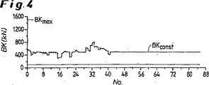
図1及び2に図示された圧延プログラムのため、図3〜6には、スタンド負荷が異なっているもしくはバックアップロール摩耗が異なっているCVCワークロールの従来の移動について期待すべき結果がプロットされている。 Because of the rolling program illustrated in FIGS. 1 and 2, FIGS. 3-6 plot the expected results for conventional movement of CVC work rolls with different stand loads or different backup roll wear. Yes.
図3及び4には、必要なワークロール移動位置VPについて得られた結果がmmで図示され(図3)、高いバックアップロール摩耗又は高いスタンド負荷に対して適用されたワークロール曲げ荷重BKがkNで図示されている(図4)。この場合図3から読み取ることができるように、この従来の運転方法では、ワークロール位置は、特に正の領域で調整され、これにより、例えばスタンドの負荷が補償される。部分的に、最大移動限度VPmaxに達している。 3 and 4, the results obtained for the required work roll movement position VP are illustrated in mm (FIG. 3) and the work roll bending load BK applied for high backup roll wear or high stand load is kN. (FIG. 4). In this case, as can be read from FIG. 3, in this conventional operating method, the work roll position is adjusted, in particular in the positive region, so that, for example, the load on the stand is compensated. In part, the maximum travel limit VPmax has been reached.
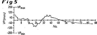
図5及び6には、図3及び4に応じて少ない中間ロール摩耗又は低いスタンド負荷に付いて得られた結果が図示されている。ワークロール移動位置VPについて得られた曲線(図5)とワークロール曲げ荷重BKについて得られた曲線(図6)は、その特徴が図3及び4の特徴と似ており、この場合、曲げ荷重がほぼ同じ場合、ワークロール移動値VPは、変更された境界条件に応じて、むしろ平均的な移動調整領域で推移している。全体的に見て、CVCワークロールの従来の移動実務では移動値が比較的小さく、圧延プログラムに応じてワークロール曲げ荷重BKがほぼ40本のストリップ以降一定に推移する(BKconst)ことが共通している。 FIGS. 5 and 6 illustrate the results obtained with low intermediate roll wear or low stand load according to FIGS. Work b Lumpur curves obtained for the movement position VP (FIG. 5) and the work roll bending curves obtained for the load BK (FIG. 6) is similar the feature is characterized in Figures 3 and 4, in this case, When the bending load is substantially the same, the work roll movement value VP changes in an average movement adjustment region depending on the changed boundary condition. Overall, the conventional movement practice of CVC work rolls has a relatively small movement value, and it is common that the work roll bending load BK stays constant after approximately 40 strips (BKconst) according to the rolling program. ing.
図7〜10には、同じ圧延プログラムについて、CVCワークロールの本発明による周期的な移動もしくはスタンド負荷が異なっている場合もしくは中間ロール摩耗が異なっている場合のワークロール曲げについて期待すべき結果がプロットされている。 7-10 show the expected results for work roll bending for the same rolling program when the cyclic movement or stand load of the CVC work roll according to the invention is different or when the intermediate roll wear is different. It is plotted.
図7及び8には、ワークロール移動位置VPについて得られた結果がmmで図示され(図7)、高い中間ロール摩耗もしくは高いスタンド負荷に対して適用されたワークロール曲げ荷重BKがkNで図示されている(図8)。図3の従来の移動の結果に対して明らかであるのは、CVCワークロールの利用される大きな調整領域であり、この場合、ワークロールは、正の領域でも、負の領域でも運転される。 In FIGS. 7 and 8, the results obtained for the work roll movement position VP are illustrated in mm (FIG. 7), and the work roll bending load BK applied to high intermediate roll wear or high stand load is illustrated in kN. (FIG. 8). What is clear with respect to the result of the conventional movement of FIG. 3 is the large adjustment area in which the CVC work roll is used, in which case the work roll is operated in both the positive and negative areas.
図9及び10には、図7及び8に応じて、少ないバックアップロール摩耗又は低いスタンド負荷について得られた結果が図示されている。ワークロール移動位置VPについて得られた曲線(図9)とワークロール曲げ荷重BKについて得られた曲線(図10)は、ここでもその特性が図7及び8の特性と似ており、この場合、曲げ荷重がほぼ同じ場合、CVCロールの周期的な移動は、変更された境界条件に応じて、むしろ負の移動調整領域で行なわれる。 FIGS. 9 and 10 illustrate the results obtained for low backup roll wear or low stand load in accordance with FIGS. The curve obtained with respect to the work roll movement position VP (FIG. 9) and the curve obtained with respect to the work roll bending load BK (FIG. 10) are again similar in characteristics to those in FIGS. If the bending load is approximately the same, the cyclic movement of the CVC roll is performed in the negative movement adjustment region, rather than in accordance with the changed boundary conditions.
本発明による周期的な移動の運転方法について特徴的であるのは、ワークロール移動位置VPとワークロール曲げ荷重BK間の逆方向の相互作用であり、これは、図で明らかになっている。負方向VPnにCVCワークロールを移動させた場合、正方向の曲げBKpが認められ、その逆も認められる。 What is characteristic of the operation method of the periodic movement according to the present invention is the interaction in the opposite direction between the work roll movement position VP and the work roll bending load BK, which is clearly shown in the figure. When the CVC work roll is moved in the negative direction VPn, the positive direction bending BKp is recognized and vice versa.
CVCワークロールの本発明による周期的な移動によって得られるワークロール摩耗の一様化は、図11及び12で明らかにされている。ここでは、mmで示したワークロール摩耗AVが、mmで示したワークロール胴長さBLにわたってプロットされており、ワークロール摩耗は、圧延プログラムの終了時に生じる。胴の中心の摩耗値がほぼ同じ場合、エッジ領域の周期的な運転方法(図11)でのロール輪郭WKは、従来の運転方法(図12)に比べて調和するように形成されているのに対し、従来の運転方法の場合は少ない移動に条件付けられて、角のある移行領域を有する急勾配の摩耗フランクが認められる。 The uniform work roll wear obtained by the cyclic movement of the CVC work roll according to the present invention is illustrated in FIGS. Here, the work roll wear AV shown in mm is plotted over the work roll body length BL shown in mm, and the work roll wear occurs at the end of the rolling program. When the wear value at the center of the cylinder is almost the same, the roll contour WK in the periodic operation method (FIG. 11) in the edge region is formed in harmony with the conventional operation method (FIG. 12). On the other hand, in the case of the conventional driving method, a steep wear flank having an angled transition region is recognized, which is conditioned for less movement.
調和的なワークロール摩耗輪郭は、ストリップの輪郭に対してプラスに作用する。従って、ストリップの膨らみの発生又は大きなストリップエッジの低下(エッジドロップ)は、効果的に補償することができる。 A harmonious work roll wear profile has a positive effect on the strip profile. Thus, the occurrence of strip bulge or large strip edge degradation (edge drop) can be effectively compensated.
AV ワークロール摩耗
BB ストリップ幅
BD 仕上げストリップ厚さ
BK ワークロール曲げ荷重
BKconst 一定の曲げ荷重
BKmax 最大曲げ荷重
BKp 正方向の曲げ
BL ワークロール胴長さ
No. コイル数
VP ワークロール移動位置
VPmax 最大移動限界
VPmin 最小移動限界
VPn 負方向の移動
VPp 正方向の移動
WK ワークロール輪郭
AV Work roll wear BB Strip width BD Finish strip thickness BK Work roll bending load BKconst Constant bending load BKmax Maximum bending load BKp Positive bending BL Work roll body length No. Number of coils VP Work roll movement position VPmax Maximum movement limit VPmin Minimum movement limit VPn Negative movement VPp Positive movement WK Work roll contour
Claims (5)
ストリップからストリップへとその調整領域の予設定された一定の部分でワークロール曲げを周期的に変更することによって、同時にワークロールの、移動調整領域が拡大された周期的な移動が励起もしくは強制され、この場合、ワークロールの移動の方向とワークロール曲げの方向がワークロールのプロフィルに対して逆に作用するようにワークロール曲げ及びワークロール移動の両調整システムの作用を組み合わせることにより、これら両調整システムの効果が相互に補完され、ワークロール移動とワークロール曲げの協働が、プロセスモデルによってオンラインで制御され、ワークロールの周期的な変更が、平面度、ストリップ輪郭品質、並びにストリッププロフィルレベルのようなストリップ品質パラメータが満足されている許容領域でのみ実施され、これらの基準を遵守するために、周期的な移動ストロークが、プロセスモデルによってオンラインで監視及び限定可能であることを特徴とする方法。Two work rolls that can move in the axial direction, a CVC polishing surface whose curved contour can be expressed by a third-order or higher polynomial, two backup rolls, and two intermediate rolls that can move in the axial direction A roll stand of a rolling line in which work roll bending or work roll movement is applied as an adjustment mechanism to control strip flatness and strip profile in order to control strip flatness and strip profile In a method for rolling a strip in
By periodically changing the work roll bend from strip to strip at a predetermined constant portion of its adjustment area, the periodic movement of the work roll with an expanded movement adjustment area is simultaneously excited or forced. In this case, by combining the actions of both the work roll bending and work roll movement adjustment systems so that the work roll movement direction and the work roll bending direction act against the work roll profile, The effects of the adjustment system are complemented with each other , the work roll movement and work roll bending cooperation is controlled online by the process model, and the cyclic change of the work roll is the flatness, strip contour quality, and strip profile level Tolerance where strip quality parameters like are satisfied Only implemented in a method to comply with these standards, a periodic movement stroke, characterized in that the process model can be monitored and limited on-line.
Applications Claiming Priority (3)
| Application Number | Priority Date | Filing Date | Title |
|---|---|---|---|
| DE102004031354A DE102004031354A1 (en) | 2004-06-28 | 2004-06-28 | Method for rolling strips in a roll stand |
| DE102004031354.7 | 2004-06-28 | ||
| PCT/EP2005/005991 WO2006000290A1 (en) | 2004-06-28 | 2005-06-03 | Mehtod for rolling strips in a roll stand |
Publications (2)
| Publication Number | Publication Date |
|---|---|
| JP2008504128A JP2008504128A (en) | 2008-02-14 |
| JP4850829B2 true JP4850829B2 (en) | 2012-01-11 |
Family
ID=34969452
Family Applications (1)
| Application Number | Title | Priority Date | Filing Date |
|---|---|---|---|
| JP2007517118A Active JP4850829B2 (en) | 2004-06-28 | 2005-06-03 | Method for rolling a strip in a roll stand |
Country Status (15)
| Country | Link |
|---|---|
| US (1) | US8096161B2 (en) |
| EP (1) | EP1761347B1 (en) |
| JP (1) | JP4850829B2 (en) |
| KR (1) | KR101146934B1 (en) |
| CN (1) | CN1976768B (en) |
| AT (1) | ATE440680T1 (en) |
| BR (1) | BRPI0509662A (en) |
| CA (1) | CA2570865C (en) |
| DE (2) | DE102004031354A1 (en) |
| ES (1) | ES2328595T3 (en) |
| RU (1) | RU2333810C2 (en) |
| TW (1) | TWI347236B (en) |
| UA (1) | UA81202C2 (en) |
| WO (1) | WO2006000290A1 (en) |
| ZA (1) | ZA200607180B (en) |
Families Citing this family (8)
| Publication number | Priority date | Publication date | Assignee | Title |
|---|---|---|---|---|
| DE102006051728B4 (en) * | 2006-10-30 | 2013-11-21 | Outokumpu Nirosta Gmbh | Method for rolling metal strips, in particular steel strips |
| US20150174648A1 (en) * | 2013-12-24 | 2015-06-25 | Posco | Method of Manufacturing Thin Martensitic Stainless Steel Sheet Using Strip Caster with Twin Rolls and Thin Martensitic Stainless Steel Sheet Manufactured by the Same |
| WO2019087284A1 (en) | 2017-10-31 | 2019-05-09 | 東芝三菱電機産業システム株式会社 | Roll wear dispersion method for rolling stand and rolling system |
| CN108213087B (en) * | 2018-01-08 | 2019-05-03 | 东北大学 | A method of dispersion CVC working roll roll shifting position |
| CN108273853B (en) * | 2018-01-19 | 2019-09-03 | 山东钢铁集团日照有限公司 | A kind of continuous hot-rolling mill working roll intelligence roller shifting method |
| EP3536411B1 (en) * | 2018-03-09 | 2020-11-18 | Primetals Technologies Germany GmbH | Avoidance of wearing edges when rolling flat rolled products |
| KR102371055B1 (en) * | 2018-03-23 | 2022-03-04 | 제이에프이 스틸 가부시키가이샤 | Cold rolling method of metal strip |
| DE102018212074A1 (en) * | 2018-07-19 | 2020-01-23 | Sms Group Gmbh | Method for determining manipulated variables for active profile and flatness actuators for a roll stand and for profile and central flatness values for hot-rolled metal strip |
Citations (6)
| Publication number | Priority date | Publication date | Assignee | Title |
|---|---|---|---|---|
| JPS60250806A (en) * | 1984-05-29 | 1985-12-11 | Kawasaki Steel Corp | Hot rolling method |
| JPS6368201A (en) * | 1986-09-09 | 1988-03-28 | Kawasaki Heavy Ind Ltd | Rolling method |
| JPH0437402A (en) * | 1990-06-04 | 1992-02-07 | Kawasaki Steel Corp | Hot finishing mill and hot finishing mill line |
| JPH05261415A (en) * | 1992-03-19 | 1993-10-12 | Hitachi Ltd | Method for controlling and rolling of rolling mill |
| JPH0615322A (en) * | 1992-07-03 | 1994-01-25 | Sumitomo Metal Ind Ltd | Sheet crown control method at time of hot rolling |
| JPH08276206A (en) * | 1995-02-09 | 1996-10-22 | Nkk Corp | Rolling mill and rolling method |
Family Cites Families (7)
| Publication number | Priority date | Publication date | Assignee | Title |
|---|---|---|---|---|
| SU1362514A1 (en) | 1981-07-17 | 1987-12-30 | Г.П.Руденский и О.И.Малыгин | Method of rolling strips |
| SU1452631A1 (en) | 1986-11-14 | 1989-01-23 | Краснодарский политехнический институт | Method of continuous rolling of sheets |
| JP2616917B2 (en) | 1987-01-24 | 1997-06-04 | 株式会社日立製作所 | Rolling method by roll shift rolling mill |
| CN1082851C (en) * | 1994-07-08 | 2002-04-17 | 石川岛播磨重工业株式会社 | Rolling method using both displacement and bending of roller, rolling machine and roller used for same |
| DE19654068A1 (en) | 1996-12-23 | 1998-06-25 | Schloemann Siemag Ag | Method and device for rolling a rolled strip |
| US6119500A (en) * | 1999-05-20 | 2000-09-19 | Danieli Corporation | Inverse symmetrical variable crown roll and associated method |
| JP3689037B2 (en) * | 2001-12-07 | 2005-08-31 | 株式会社日立製作所 | Tandem rolling mill shape control method and apparatus |
-
2004
- 2004-06-28 DE DE102004031354A patent/DE102004031354A1/en not_active Withdrawn
-
2005
- 2005-03-06 UA UAA200610676A patent/UA81202C2/en unknown
- 2005-06-03 AT AT05748365T patent/ATE440680T1/en active
- 2005-06-03 US US11/630,935 patent/US8096161B2/en active Active
- 2005-06-03 DE DE502005007991T patent/DE502005007991D1/en active Active
- 2005-06-03 WO PCT/EP2005/005991 patent/WO2006000290A1/en active Application Filing
- 2005-06-03 CN CN2005800216537A patent/CN1976768B/en active Active
- 2005-06-03 BR BRPI0509662-6A patent/BRPI0509662A/en not_active IP Right Cessation
- 2005-06-03 JP JP2007517118A patent/JP4850829B2/en active Active
- 2005-06-03 KR KR1020067019881A patent/KR101146934B1/en not_active IP Right Cessation
- 2005-06-03 CA CA2570865A patent/CA2570865C/en not_active Expired - Fee Related
- 2005-06-03 EP EP05748365A patent/EP1761347B1/en active Active
- 2005-06-03 ES ES05748365T patent/ES2328595T3/en active Active
- 2005-06-03 RU RU2006135636/02A patent/RU2333810C2/en active
- 2005-06-06 TW TW094118565A patent/TWI347236B/en not_active IP Right Cessation
-
2006
- 2006-08-25 ZA ZA200607180A patent/ZA200607180B/en unknown
Patent Citations (6)
| Publication number | Priority date | Publication date | Assignee | Title |
|---|---|---|---|---|
| JPS60250806A (en) * | 1984-05-29 | 1985-12-11 | Kawasaki Steel Corp | Hot rolling method |
| JPS6368201A (en) * | 1986-09-09 | 1988-03-28 | Kawasaki Heavy Ind Ltd | Rolling method |
| JPH0437402A (en) * | 1990-06-04 | 1992-02-07 | Kawasaki Steel Corp | Hot finishing mill and hot finishing mill line |
| JPH05261415A (en) * | 1992-03-19 | 1993-10-12 | Hitachi Ltd | Method for controlling and rolling of rolling mill |
| JPH0615322A (en) * | 1992-07-03 | 1994-01-25 | Sumitomo Metal Ind Ltd | Sheet crown control method at time of hot rolling |
| JPH08276206A (en) * | 1995-02-09 | 1996-10-22 | Nkk Corp | Rolling mill and rolling method |
Also Published As
| Publication number | Publication date |
|---|---|
| WO2006000290A1 (en) | 2006-01-05 |
| TWI347236B (en) | 2011-08-21 |
| TW200609048A (en) | 2006-03-16 |
| KR101146934B1 (en) | 2012-05-22 |
| EP1761347B1 (en) | 2009-08-26 |
| CN1976768A (en) | 2007-06-06 |
| CA2570865A1 (en) | 2006-01-05 |
| ZA200607180B (en) | 2008-04-30 |
| ES2328595T3 (en) | 2009-11-16 |
| BRPI0509662A (en) | 2007-10-09 |
| US20070199363A1 (en) | 2007-08-30 |
| EP1761347A1 (en) | 2007-03-14 |
| US8096161B2 (en) | 2012-01-17 |
| CN1976768B (en) | 2012-11-14 |
| CA2570865C (en) | 2012-03-13 |
| RU2006135636A (en) | 2008-04-20 |
| ATE440680T1 (en) | 2009-09-15 |
| DE502005007991D1 (en) | 2009-10-08 |
| UA81202C2 (en) | 2007-12-10 |
| KR20070021167A (en) | 2007-02-22 |
| JP2008504128A (en) | 2008-02-14 |
| DE102004031354A1 (en) | 2006-01-19 |
| RU2333810C2 (en) | 2008-09-20 |
Similar Documents
| Publication | Publication Date | Title |
|---|---|---|
| JP4850829B2 (en) | Method for rolling a strip in a roll stand | |
| US4864836A (en) | Rolling method making use of work roll shift rolling mill | |
| RU2391154C2 (en) | Crown roller controlling profile and rolled strip flatness | |
| RU2442669C2 (en) | Roll housing for strips or plates manufacturing | |
| CN1198967A (en) | Method for influence on edge shape of rolled strip | |
| RU2487770C2 (en) | Method of making, at least, one working forming roll for material rolling | |
| US11938528B2 (en) | Method for ascertaining control variables for active profile and flatness control elements for a rolling stand and profile and average flatness values for hot-rolled metal strip | |
| CN114769325B (en) | Control method for hot continuous rolling CVC working roll shifting | |
| CN111801173B (en) | Edge wear prevention during rolling of flat rolling stock | |
| US4910988A (en) | Method for rolling metal sheets | |
| JP3933325B2 (en) | Rolling mill | |
| JP2825984B2 (en) | Hot finish rolling apparatus and rolling method for metal sheet | |
| JP7512990B2 (en) | Method for cold rolling metal strip and method for repairing backup roll | |
| JPH0275404A (en) | Roll for drafting web thickness of shape stock | |
| EP1322435B1 (en) | Method to control the axial forces generated between the rolling rolls | |
| JPH02117708A (en) | Method for wet skin pass rolling of thin steel sheet | |
| JPS62282710A (en) | Rolling method | |
| JPH0691498A (en) | Grinding method of rolling machine | |
| JPH07290116A (en) | Rolling mill and rolling method | |
| JP2019107657A (en) | Caliber pressure roll, rolling mill, caliber rolling method and manufacturing method of shape steel | |
| SU1570809A1 (en) | Method of hot rolling of strips from aluminium and alloys thereof | |
| JPH08332510A (en) | Method for rolling steel sheet | |
| JPH05154509A (en) | Hot finishing mill | |
| JP2001321808A (en) | Equipment for rolling wide flange shape and method for rolling using the equipment | |
| JPH06262229A (en) | Method for controlling sheet crown by work roll shifting method |
Legal Events
| Date | Code | Title | Description |
|---|---|---|---|
| A621 | Written request for application examination |
Free format text: JAPANESE INTERMEDIATE CODE: A621 Effective date: 20080404 |
|
| A977 | Report on retrieval |
Free format text: JAPANESE INTERMEDIATE CODE: A971007 Effective date: 20091026 |
|
| A131 | Notification of reasons for refusal |
Free format text: JAPANESE INTERMEDIATE CODE: A131 Effective date: 20091117 |
|
| A521 | Request for written amendment filed |
Free format text: JAPANESE INTERMEDIATE CODE: A523 Effective date: 20100215 |
|
| RD04 | Notification of resignation of power of attorney |
Free format text: JAPANESE INTERMEDIATE CODE: A7424 Effective date: 20100517 |
|
| A02 | Decision of refusal |
Free format text: JAPANESE INTERMEDIATE CODE: A02 Effective date: 20110301 |
|
| A521 | Request for written amendment filed |
Free format text: JAPANESE INTERMEDIATE CODE: A523 Effective date: 20110608 |
|
| A911 | Transfer to examiner for re-examination before appeal (zenchi) |
Free format text: JAPANESE INTERMEDIATE CODE: A911 Effective date: 20110615 |
|
| TRDD | Decision of grant or rejection written | ||
| A01 | Written decision to grant a patent or to grant a registration (utility model) |
Free format text: JAPANESE INTERMEDIATE CODE: A01 Effective date: 20110920 |
|
| A01 | Written decision to grant a patent or to grant a registration (utility model) |
Free format text: JAPANESE INTERMEDIATE CODE: A01 |
|
| A61 | First payment of annual fees (during grant procedure) |
Free format text: JAPANESE INTERMEDIATE CODE: A61 Effective date: 20111019 |
|
| R150 | Certificate of patent or registration of utility model |
Ref document number: 4850829 Country of ref document: JP Free format text: JAPANESE INTERMEDIATE CODE: R150 |
|
| FPAY | Renewal fee payment (event date is renewal date of database) |
Free format text: PAYMENT UNTIL: 20141028 Year of fee payment: 3 |
|
| R250 | Receipt of annual fees |
Free format text: JAPANESE INTERMEDIATE CODE: R250 |
|
| R250 | Receipt of annual fees |
Free format text: JAPANESE INTERMEDIATE CODE: R250 |
|
| R250 | Receipt of annual fees |
Free format text: JAPANESE INTERMEDIATE CODE: R250 |
|
| R250 | Receipt of annual fees |
Free format text: JAPANESE INTERMEDIATE CODE: R250 |
|
| R250 | Receipt of annual fees |
Free format text: JAPANESE INTERMEDIATE CODE: R250 |
|
| R250 | Receipt of annual fees |
Free format text: JAPANESE INTERMEDIATE CODE: R250 |
|
| R250 | Receipt of annual fees |
Free format text: JAPANESE INTERMEDIATE CODE: R250 |
|
| R250 | Receipt of annual fees |
Free format text: JAPANESE INTERMEDIATE CODE: R250 |
|
| R250 | Receipt of annual fees |
Free format text: JAPANESE INTERMEDIATE CODE: R250 |
|
| R250 | Receipt of annual fees |
Free format text: JAPANESE INTERMEDIATE CODE: R250 |