JP4850002B2 - Pipe cutting device - Google Patents
Pipe cutting device Download PDFInfo
- Publication number
- JP4850002B2 JP4850002B2 JP2006240288A JP2006240288A JP4850002B2 JP 4850002 B2 JP4850002 B2 JP 4850002B2 JP 2006240288 A JP2006240288 A JP 2006240288A JP 2006240288 A JP2006240288 A JP 2006240288A JP 4850002 B2 JP4850002 B2 JP 4850002B2
- Authority
- JP
- Japan
- Prior art keywords
- handle
- slide member
- fulcrum
- rack
- workpiece
- Prior art date
- Legal status (The legal status is an assumption and is not a legal conclusion. Google has not performed a legal analysis and makes no representation as to the accuracy of the status listed.)
- Active
Links
Images


Description
本発明は、管材を切断する管材切断装置に関するものである。 The present invention relates to a pipe material cutting device for cutting a pipe material.
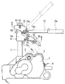
従来、金属管を切断する装置として、特許文献1に示されるような管材切断装置が提案されている。この管材切断装置は、図8に示されるように、装置本体51の上面に設けられた2つの駆動ローラ部材52で、管材53を回転させて、略円盤形状のカッタホイール54を押し下げ、管材53をカッタホイール54と駆動ローラ部材52で挟んで、管材53を切断する装置であるが、外径の異なる管材53にも対応するために、カッタホイール54を押し下げる、押下機構55が昇降可能となっている。
Conventionally, as a device for cutting a metal tube, a pipe material cutting device as shown in
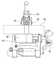
この押下機構55は、図9に示されるように、支柱56内に装着されてスライド部材57を上方に付勢するスライドばね58と、スライド部材57に取り付けられてスライド部材57の上昇をロックするラチェット部材59と、カッタホイール54を管材53位置まで押し下げるレバーハンドル61から構成されている。ラチェット部材59は支柱56の前面側に形成されたラチェット溝62とスライド部材57に枢着されるラチェット爪59aとからなり、ラチェット爪59aはラチェット爪59aを時計回り方向に付勢するばね64によりラチェット溝62に圧着係止されているが、ラチェット爪59a形状はスライド部材57に押し下げる力が加わった際にはラチェット爪59aはラチェット溝62から外れて下降を許すが、スライドばね58によりスライド部材57に上昇力が加えられた状態ではラチェット爪59aはラチェット溝62に食い込んで上昇は許さないようになっている。
As shown in FIG. 9, the push-
レバーハンドル61を押し上げる方向に持ち上げると、レバーハンドル61の基端に設けられた突起61aが、ラチェット部材59に設けられた解除突起59bを押圧し、ラチェット部材59が回動して、ラチェット爪59aとラチェット溝62の食い込みが外れてスライド部材57が昇降自在となり、カッタホイール11を管材の外径に合わせることが可能となる。
When the
レバーハンドル61を押し下げる方向に回動させると、レバーハンドル61の基端に設けられたカム61bが、スライド部材57に軸支点67に軸支されている遊動アーム66を押圧し、遊動アーム66が軸支点67を中心に回動し、カッタホイール54が下降する構造となっている。
When the
しかしながら、この押下機構55は多数の部品から構成されることから、コスト高になり、また装置重量が重くなってしまうという問題があった。
However, since the
この管材切断装置には、カッタホイール54と同軸に切断補助用押さえローラ65が軸支されている。この切断補助用押えローラ65は、カッタホイール54が、管材53である被加工物の肉厚を越えて切り込まれて被加工物に対する回転駆動力が失われた際、駆動ローラ部材52に被加工物を押し付けて回転力を被加工物に与えるものである。カッタホイール54と切断補助用押えローラ65との外径差は被加工物の略肉厚分であればよく、最大加工径と最小加工径では肉厚は異なるがその差は弾性を有する切断補助用押えローラ65により吸収するものである。しかしながら、被加工物の異なる肉厚を切断補助用押さえローラ65の弾性で吸収していたので吸収幅が狭く、厚肉の管材を切断することができず、異なる肉厚の管材に十分に対応することができないという問題があった。
In this tube cutting apparatus, a cutting assisting pressing
一方で、この管材切断装置の側部には、図8に示されるように、管材の切断断面のバリを取り、仕上げを良好とするために、駆動ローラ52と連動して回転駆動するリーマ70か設けられているが、このリーマ70は、管材切断装置から突出しているので、全幅が大きくなってしまうという問題があった。また、このリーマ70は錐形状であり、切断された管材を手で持って、回転するリーマ70に管材の切断面を斜めに当てて、管材の切断面を順次当ててバリを取るので、バリ取り作業が煩雑となるという問題があった。
本発明は、上記した従来の問題点を解決し、部品点数を削減し、コスト高にならず、軽量・小型で、異なる肉厚の管材に十分に対応することができ、バリ取り作業が簡易な管材切断装置を提供する。 The present invention solves the above-mentioned conventional problems, reduces the number of parts, does not increase the cost, is light and small, can sufficiently cope with pipes of different wall thickness, and simplifies deburring work. A tubular material cutting device is provided.
上記課題を解決するためになされた本発明は、 装置本体上部に設けられた、被加工物を受けて回転させる駆動ローラ部材と、本体に立設された支柱と、この支柱に昇降可能に取り付けられたスライド部材と、前記スライド部材に回転可能に取り付けられた略円盤形状のカッタホイールを有し、被加工物を前記駆動ローラ部材と前記カッタホイールで挟んで被加工物を外周面から切断する管材切断装置において、前記支柱にラックを設け、前記スライド部材の上部の第1支点にリンク部材を回動自在に軸支し、前記リンク部材の前記ラック側先端の第2支点に、前記ラックと係合し、第2支点をピッチ円の中心とするピニオンギアが形成されたハンドルを軸支し、所定のハンドル位置からハンドルを押し下げると、前記ラックと前記ピニオンギアが係合し、前記スライド部材が下降するが、所定のハンドル位置からハンドルを押し上げると、前記ラックと前記ピニオンギアの係合が外れ、スライド部材が昇降自在になることを特徴とするものである。 In order to solve the above problems, the present invention includes a driving roller member provided on the upper part of the apparatus body for receiving and rotating a workpiece, a support column installed on the body, and attached to the support column so as to be movable up and down. And a substantially disc-shaped cutter wheel rotatably attached to the slide member, and the workpiece is cut from the outer peripheral surface with the workpiece sandwiched between the drive roller member and the cutter wheel. In the tubular material cutting device, a rack is provided on the support column, a link member is pivotally supported on a first fulcrum on the upper part of the slide member, and the rack is mounted on a second fulcrum of the link-side tip of the link member. The rack and the pinion are engaged with each other by pivotally supporting a handle on which a pinion gear having the second fulcrum as the center of the pitch circle is formed and pushing the handle down from a predetermined handle position. The slide member is lowered, but when the handle is pushed up from a predetermined handle position, the rack and the pinion gear are disengaged, and the slide member can be raised and lowered. is there.
なお、ハンドルにリンク部材と当接する突起を設け、ハンドルを押し上げ、前記突起がリンク部材と当接すると、ハンドルが第1支点を中心に回動して、ラックとギアの係合が外れ、スライド部材が昇降自在となることが好ましい。 When the handle is provided with a protrusion that contacts the link member, the handle is pushed up, and when the protrusion contacts the link member, the handle rotates about the first fulcrum, disengaging the rack and the gear, and sliding. It is preferable that the member can be raised and lowered.
また、スライド部材は、上方に付勢されていることが好ましい。 Moreover, it is preferable that the slide member is urged upward.
また、スライド部材に、その先端が下方に付勢されるアームを回動自在に軸支し、このアームの先端に切断補助用押さえローラを回転可能に軸支することが好ましい。 Further, it is preferable that an arm whose tip is biased downward is pivotally supported on the slide member, and a cutting assisting pressing roller is pivotally supported on the tip of the arm.
駆動ローラと連動して回転駆動される、円錐面に少なくとも1つの刃が設けられた略円錐形状のリーマを、このリーマの先端が装置本体から突出しないように、装置本体の内部に配設することが好ましい。 A substantially conical reamer that is rotationally driven in conjunction with the drive roller and has a conical surface provided with at least one blade is disposed inside the apparatus main body so that the tip of the reamer does not protrude from the apparatus main body. It is preferable.
支柱にラックを設け、スライド部材の上部の第1支点にリンク部材を回動自在に軸支し、リンク部材の前記ラック側先端の第2支点に、前記ラックと係合し、第2支点をピッチ円の中心とするピニオンギアが形成されたハンドルを軸支したので、従来に比べ部品点数の削減が可能となり、コスト削減に寄与しつつ、装置の軽量化も可能となる。 A rack is provided on the support column, the link member is pivotally supported on the first fulcrum at the upper part of the slide member, the second fulcrum at the end of the link side of the link member is engaged with the rack, and the second fulcrum is Since the handle on which the pinion gear at the center of the pitch circle is formed is pivotally supported, the number of parts can be reduced as compared with the prior art, and the weight of the apparatus can be reduced while contributing to cost reduction.
ハンドルにリンク部材と当接する突起を設けると、ハンドルを押し上げ、前記突起がリンク部材と当接すると、ハンドルが第1支点を中心に回動して、ラックとギアの係合が外れ、スライド部材が昇降自在となるので、管材の外径に合わせて、スライド部材を昇降させることが可能となり、異なる外径の管材を切断することが可能となる。また、従来に比べ部品点数の削減が可能となり、コスト削減に寄与しつつ、装置の軽量化も可能となる。 If the handle is provided with a protrusion that contacts the link member, the handle is pushed up, and when the protrusion contacts the link member, the handle rotates about the first fulcrum to disengage the rack from the gear, and the slide member Therefore, the slide member can be raised and lowered in accordance with the outer diameter of the pipe material, and the pipe materials having different outer diameters can be cut. Further, the number of parts can be reduced as compared with the conventional case, and the weight of the apparatus can be reduced while contributing to cost reduction.
スライド部材を、上方に付勢するように構成すると、ハンドル押し上げる向きに回動させる一動作で、瞬時に復帰状態になるので、作業毎にサイズ(外径)の異なる被加工物であっても、切断後は瞬時に復帰状態にすることができ、この状態からスライド部材を押し下げるように、ハンドルを操作するだけで、管材を切断することができ、連続した管材の切断下降に要する時間を短縮することができ、生産性を向上させることが可能となる。 If the slide member is configured to be biased upward, it can be instantly returned by one operation of rotating the handle in the direction of pushing up the handle, so even if the workpiece has a different size (outer diameter) for each work. After cutting, the tube can be instantly returned to the state, and the tube can be cut simply by operating the handle so that the slide member is pushed down from this state, reducing the time required for continuous cutting and lowering of the tube. It is possible to improve productivity.
スライド部材に、その先端が下方に付勢されるアームを回動自在に第3支点で軸支し、このアームの先端に切断補助用押さえローラを回転可能に軸支すると、異なる肉厚の被切断材を切断することが可能となる。 When a slide member is pivotally supported by a third fulcrum with an arm whose tip is biased downward, and a cutting assisting presser roller is pivotally supported at the tip of this arm, the arm of different thickness is covered. The cutting material can be cut.
リーマを駆動ローラと連動して回転駆動するように構成すると、リーマを回転駆動するための電動モータを設ける必要がなく、軽量で小型な管材切断装置を提供することが可能となる。また、リーマの先端が装置本体から突出しないように、装置本体の内部に配設すると、装置本体の外郭がリーマの回転を保護する安全カバーの役割を果たし、安全である。また、リーマが装置本体から突出していないので足等でリーマの先端を引っかけることがない、安全な管材切断装置を提供することが可能となり、また、軽量で小型な管材切断装置を提供することが可能となる。また、リーマを、円錐面に少なくとも1つの刃が設けられた略円錐形状のリーマとすると、管材を切断後に、管材をリーマにリーマの回転軸方向に向かって当てるだけでバリ取り作業が完了し、従来と比べて簡単且つ確実にバリを取ることが可能となる。 When the reamer is configured to rotate in conjunction with the drive roller, it is not necessary to provide an electric motor for rotating the reamer, and a light and small tube cutting device can be provided. Further, when the reamer is disposed inside the apparatus main body so that the tip of the reamer does not protrude from the apparatus main body, the outer shell of the apparatus main body serves as a safety cover that protects the rotation of the reamer and is safe. Further, since the reamer does not protrude from the apparatus main body, it is possible to provide a safe tube cutting device that does not catch the tip of the reamer with a foot or the like, and it is also possible to provide a lightweight and small tube cutting device. It becomes possible. In addition, if the reamer is a substantially conical reamer with at least one blade provided on the conical surface, the deburring operation is completed simply by applying the pipe material to the reamer in the direction of the reamer's rotation axis after cutting the pipe material. Therefore, it is possible to remove the burrs easily and reliably as compared with the conventional case.
以下に、図面を参照しつつ本発明の好ましい実施の形態を示す。
図1は本発明の実施の形態を示す管材切断装置の側面図であり、図2は本発明の実施の形態を示す管材切断装置の正面図であり、図3は図1の反対側から見た管材切断装置の側面図であり、図4は図1のA−A断面の断面図であり、ギアの構成を示している。図1において、1は箱形形状をした装置本体である。この装置本体1の上部は開口していて、駆動ローラ2と従動ローラ3が同じ高さに並設して、装置本体1の上部に回転可能に軸支されている。駆動ローラ2と従動ローラ3は、同一もしくはほぼ同じ外径の金属円筒である。駆動ローラ2と従動ローラ3は、互いに近設していて、駆動ローラ2と従動ローラ3の間の凹部で、管材である被加工物を受けるようにしている。これらの駆動ローラ2と従動ローラ3の表面には、後述するカッタホイール11が介入することができる凹溝2a、3aが形成されている。
Hereinafter, preferred embodiments of the present invention will be described with reference to the drawings.
FIG. 1 is a side view of a pipe cutting apparatus showing an embodiment of the present invention, FIG. 2 is a front view of the pipe cutting apparatus showing an embodiment of the present invention, and FIG. 3 is viewed from the opposite side of FIG. 4 is a side view of the tubular material cutting device, and FIG. 4 is a cross-sectional view taken along the line AA of FIG. 1, showing the configuration of the gear. In FIG. 1,
駆動ローラ2は、図4に示されるように、複数のギアを介して、電動モータ5で回転駆動される。複数のギアは、電動モータ5を減速する第1のギア21と、この第1のギア21と噛合して減速する第2のギア22、この第2のギア22と噛合して減速する第3のギア23と、この第3のギア23と噛合し増速する、駆動ローラ2と同軸に設けられた第4のギア24から構成されている。
As shown in FIG. 4, the
一方で、従動ローラ3は、電動モータ5で回転駆動されずに、装置本体1に回転可能に軸支されている。
On the other hand, the driven
装置本体1には、電動モータ5に電源を投入・遮断するトグルスイッチ6が取り付けられている。
A
装置本体1の駆動ローラ2の後方には、円柱形状の支柱7が立設されている。この支柱7の駆動ローラ2側の外表面には、ラック7aが形成されている。支柱7には、この支柱7を抱擁する抱擁部8aと、この抱擁部8aから駆動ローラ2側に水平に突設されたアーム部8bから構成されるスライド部材8が昇降可能に取り付けられている。このアーム部8bの先端部分は、管材切断装置の幅方向に2股になっている。
A
図5に示されるように、支柱7の上部には、長手方向を高さ方向とする長穴7bが設けられ、この長穴7b及びスライド部材8を貫通する支軸19が、長穴7b内をスライド可能に取り付けられている。支柱7の内部には、コイルスプリング10が設けられ、このコイルスプリング10は圧縮された状態で、その下端が支柱7を貫通する軸7cと当接し、その上端がスライド部材8を貫通する支軸19と当接し、スライド部材8を上方に弾発付勢している。
As shown in FIG. 5, a
図6に図1のB−B断面図を示す。図5及び図6に示されるように、スライド部材8のアーム部8bの2股部分の間に、カッタホイール11が回転可能に軸支されている。このカッタホイール11の外縁は、図6に示されるように、鋭角な刃状になっている。カッタホイール11の中心軸線と各種径の異なる被加工物の中心軸線とは常に垂直面上にあるように構成されている。このように構成することにより、カッタホイール11の被加工物への押し付け力は的確に、駆動ローラ2及び従動ローラ3から構成される駆動ローラ部材へ伝達され、被加工物がスリップしたり、駆動ローラ部材から脱落したりすることがないようにしている。
FIG. 6 is a sectional view taken along line BB in FIG. As shown in FIGS. 5 and 6, the
スライド部材8のアーム部8bの両側には、その先端を下側にむけた略L字形状のアーム12が、回動可能に、アーム部8bの先端と基端の間の第3支点43で軸支されている。アーム12の先端は、第3支点43に取り付けられたトーションスプリング13で、常に下側に付勢されている。アーム12の先端は、管材切断装置の幅方向に2股になっていて、そのアーム12の先端には、ウレタンや合成ゴム等の柔軟な材料で成形された、略円柱形状の切断補助用押さえローラ14が、回転可能に軸支されている。
On both sides of the
カッタホイール11と切断補助用押さえローラ14は、図1に示されるように、管材切断装置の前後方向に関しては、ほぼ同軸にしてあるが、図2に示されるように、上下方向に関しては、切断補助用押さえローラ14の回転軸方が、カッタホイール11の回転軸より僅かに下側にしてあり、切断補助用押さえローラ14の下端の方が、カッタホイール11の下端より僅かに、下側になるよう構成している。
As shown in FIG. 1, the
図1に示されるように、スライド部材8の上部の第1支点41には、断面形状が略コの字形状のリンク部材15が、その開口部をカッタホイール11側に向けて、スライド部材8を抱擁するように、前述した支軸19によって回動自在に軸支されている。
As shown in FIG. 1, a
リンク部材15のラック7a側先端の第2支点42には、パイプ形状のハンドル16が回動可能に軸支されている。このハンドル16の先端には、合成樹脂等の柔軟な材料で成型された、グリップ16aが取り付けられている。ハンドル16の軸支部には、第2支点42をピッチ円の中心とするピニオンギア16bが設けられている。このピニオンギア16bは、支柱7に設けられたラック7aと係合する。
A pipe-shaped
ハンドル16の、第2支点42よりもややハンドル16の先端側の両側には、突起16cが管材切断装置の幅方向に突設されている。この突起16cは、ハンドル16を押し上げて回動させると、リンク部材15の突起受15aと当接するように構成されている。
On both sides of the
このように構成したので、突起16cがリンク部材15の突起受15aと当接する所定のハンドル位置からハンドル16を押し上げると、ラック7aとピニオンギア16bの係合が外れ、スライド部材が昇降自在になる。一方で、所定のハンドル位置からハンドル16を押し下げると、ラック7aとピニオンギア16bが係合し、スライド部材8が下降する。
With this configuration, when the
次に、本発明の管材切断装置の作用について説明する。駆動ローラ2と従動ローラ3から構成される駆動ローラ部材上に、管材である被加工物を載せる。ハンドル16を押し上げて回動させると、ハンドル16に突設された突起16cが、リンク部材15の突起受15aと当接する。ハンドル16は、突起16cと突起受15aが当接する所定のハンドル位置までは、第2支点42を中心に回動するが、突起16cと突起受15aが当接した後に(所定のハンドル位置)、さらにハンドル16を押し上げると、ハンドル16の第2支点42を中心とする回動が抑止され、ハンドル16は第1支点41を中心に回動する。ハンドル16が、第1支点41を中心に回動すると、ハンドル16に設けられたピニオンギア16bと支軸7に設けられたラック7aとの係合が外れ、(図7の状態)スライド部材8が昇降自在となる。
Next, the operation of the pipe cutting device of the present invention will be described. A workpiece, which is a tube material, is placed on a driving roller member composed of the driving
被加工物の外径に合わせて、切断補助用押さえローラ14の先端が被加工物に接触するまでスライド部材8を下降させる。この状態でハンドル16を押し下げて回動させると、ピニオンギア16bとラック7aが係合する。さらにハンドル16を押し下げて回動させると、ピニオンギア16bが回動し、順次ラック7aと噛み合うので、スライド部材8が下降し、被加工物が駆動ローラ部材と切断補助用押さえローラ14で挟まれた状態となる。
In accordance with the outer diameter of the workpiece, the
この状態で、トグルスイッチ6を操作して、電源を投入して、駆動ローラ2を回転させる。
In this state, the
さらにハンドル16を押し下げて回動させると、スライド部材8が下降し、スライド部材8に軸支されているカッタホイール11も下降する。一方で、切断補助用押さえローラ14は、被加工物と当接しているので、下降することはできず、切断補助用押さえローラ14及アーム12は、第3支点43を中心にスライド部材8に対して上方に回動する。すると、カッタホイール11の下端が、切断補助用押さえローラ14の下端より相対的に突出して、カッタホイール11が被加工物に接触する。
When the
更にハンドル16を押し下げると、カッタホイール11は被加工物を強く押圧し、被加工物とローラ部材との摩擦力が高まり、被加工物に強い回転力が加えられ、被加工物はスリップすることなく確実に回転される。
When the
カッタホイール11の被加工物への切り込みに応じてハンドル16を押し下げて切り込みを行ってゆき、カッタホイール11が被加工物の肉厚を超える切り込みが行われると、カッタホイール11と駆動ローラ部材により被加工物への回転力の伝達が行われなくなる。しかし、切断補助用押えローラ14は被加工物を押圧するので、被加工物には強い回転力が加えられることとなる。これによりカッタホイール11は肉厚を越えて被加工物の切断を続行されることとなり、切断補助用押えローラ14に押圧されて被加工物が略一回転すると被加工物は切り落とされることとなる。
In response to the cutting of the
このように、ハンドル16を押し下げると、切断補助用押さえローラ14が第3支点43を中心にスライド部材8に対して上方に回動して、カッタホイール11の被加工物への切り込みに応じて、切断補助用押さえローラ14が追従して、被加工物を押さえるので、厚肉の被加工物も切断することが可能となり、異なる肉厚の被加工物にも十分対応することが可能となる。
In this way, when the
管材の切断作業が終了して、ハンドル16を押し上げる向きに回動させると、前述したように、ピニオンギア16bとラック7aの係合が外れ、スライド部材8は上方に付勢されているので、図5に示されるように、支軸19が長穴7bの上端と当接する位置までスライド部材8は自動的に上方に持ち上がり、瞬時に復帰状態になる。このように、ハンドル16を押し上げる向きに回動させる一動作で、瞬時に復帰状態になるので、作業毎にサイズ(外径)の異なる管材を切断する場合であっても、切断後は瞬時に復帰状態にすることができ、この状態からスライド部材8を押し下げるように、ハンドル16を操作するだけで、管材を切断することができ、連続した管材の切断下降に要する時間を大幅に短縮することができ、生産性を向上させることが可能となる。
When the tube material cutting operation is completed and the
次に、バリ取り用のリーマについて説明する。切断後の管材の切断面にはバリが発生する。そのため、図3や図4に示されるように、装置本体1の側面にはリーマ17が設けられている。このリーマ17は、円錐面に少なくとも1つの刃が設けられた略円錐形状のリーマであり、実施形態では、1つの刃17aが設けられている。このリーマ17を包容するように、底部を有する円筒形状の切粉カバー17bが配設され、切粉の飛散を防止している。図4に示されるように、リーマ17は、第3のギア23と同軸に設けられた軸23aにチャックされて、駆動ローラ2と連動して回転駆動される。このように、駆動ローラ2を駆動する第3のギア23にリーマ17をチャックしたので、リーマ17を駆動するための電動モータを設ける必要がない。なお、第3のギア23は第4のギア24よりギア比が大きいので、リーマ17の回転速度はギア2の回転速度より遅い。
Next, the deburring reamer will be described. A burr | flash generate | occur | produces in the cut surface of the pipe material after a cutting | disconnection. Therefore, as shown in FIGS. 3 and 4, a
図4に示すように、リーマ17は、リーマ17の先端が装置本体1から突出しないように、装置本体1の内部に配設されている。このように、リーマ17の先端が装置本体1から突出しないように構成したので、装置本体1の外郭がリーマの回転を保護する安全カバーの役割を果たし、安全である。また、装置本体1からリーマ17が突出していないので、足等でリーマ17を引っかけることがなく、安全である。また、全幅が大きくなることがない。
As shown in FIG. 4, the
管材を切断後は、管材の切断面をリーマ17に、リーマ17の回転軸方向に向かって当てるだけで、管材の切断面のバリ取り作業が完了する。
After cutting the pipe material, the deburring operation of the cut surface of the pipe material is completed simply by applying the cut surface of the pipe material to the
以上、現時点において、もっとも、実践的であり、かつ好ましいと思われる実施形態に関連して本発明を説明したが、本発明は、本願明細書中に開示された実施形態に限定されるものではなく、請求の範囲および明細書全体から読み取れる発明の要旨あるいは思想に反しない範囲で適宜変更可能であり、そのような変更を伴う管材切断工具もまた技術的範囲に包含されるものとして理解されなければならない。 Although the present invention has been described above in connection with the most practical and preferred embodiments at the present time, the present invention is not limited to the embodiments disclosed herein. The scope of the invention can be changed as appropriate without departing from the spirit or concept of the invention that can be read from the claims and the entire specification, and a tube cutting tool accompanying such changes should also be understood as being included in the technical scope. I must.
1 装置本体
2 駆動ローラ
2a 凹溝
3 従動ローラ
3a 凹溝
5 電動モータ
6 トグルスイッチ
7 支柱
7a ラック
7b 長穴
7c 軸
8 スライド部材
8a 抱擁部
8b アーム部
9 第1支軸
10 コイルスプリング
11 カッタホイール
12 アーム
13 トーションスプリング
14 切断補助用押さえローラ
15 リンク部材
15a 突起受
16 ハンドル
16a グリップ
16b ピニオンギア
16c 突起
17 リーマ
17a 刃
17b 切粉カバー
19 支軸
21 第1のギア
22 第2のギア
23 第3のギア
23a 軸
24 第4のギア
41 第1支点
42 第2支点
43 第3支点
51 装置本体
52 駆動ローラ部材
53 管材
54 カッタホイール
55 押下機構
56 支柱
57 スライド部材
58 スライドばね
59 ラチェット部材
59a ラチェット爪
59b 解除突起
61 レバーハンドル
62 ラチェット溝
63 ラチェット爪
64 ばね
65 切断補助用押さえローラ
66 遊動アーム
70 リーマ
DESCRIPTION OF
Claims (5)
Priority Applications (1)
| Application Number | Priority Date | Filing Date | Title |
|---|---|---|---|
| JP2006240288A JP4850002B2 (en) | 2006-09-05 | 2006-09-05 | Pipe cutting device |
Applications Claiming Priority (1)
| Application Number | Priority Date | Filing Date | Title |
|---|---|---|---|
| JP2006240288A JP4850002B2 (en) | 2006-09-05 | 2006-09-05 | Pipe cutting device |
Publications (2)
| Publication Number | Publication Date |
|---|---|
| JP2008062313A JP2008062313A (en) | 2008-03-21 |
| JP4850002B2 true JP4850002B2 (en) | 2012-01-11 |
Family
ID=39285460
Family Applications (1)
| Application Number | Title | Priority Date | Filing Date |
|---|---|---|---|
| JP2006240288A Active JP4850002B2 (en) | 2006-09-05 | 2006-09-05 | Pipe cutting device |
Country Status (1)
| Country | Link |
|---|---|
| JP (1) | JP4850002B2 (en) |
Families Citing this family (8)
| Publication number | Priority date | Publication date | Assignee | Title |
|---|---|---|---|---|
| EP2591240B1 (en) * | 2010-07-09 | 2016-04-20 | Esab AB | Roller bed with electrical clutch |
| DE102011014791A1 (en) * | 2011-03-14 | 2012-09-20 | REMS-WERK Christian Föll und Söhne GmbH | Pipe deburrer, in particular for pipes of pressfitting systems, and deburring device with such a pipe deburrer |
| FI123764B (en) * | 2011-07-06 | 2013-10-31 | Exact Tools Oy | Apparatus for machining a tubular piece |
| CN107052806B (en) * | 2017-06-21 | 2022-03-29 | 王欣怡 | Pipe cutting machine with chamfering device |
| CN108326375A (en) * | 2018-03-26 | 2018-07-27 | 奥美森智能装备股份有限公司 | A kind of processing unit (plant) of pipe fitting |
| CN109434183A (en) * | 2019-01-07 | 2019-03-08 | 开滦能源化工股份有限公司吕家坨矿业分公司 | A kind of major diameter tubing cutter special |
| CN111843024A (en) * | 2020-07-24 | 2020-10-30 | 南京道卡机电科技有限公司 | Fixed effectual steel pipe cutting equipment |
| CN114101762A (en) * | 2021-11-05 | 2022-03-01 | 徐州华正铸业有限公司 | Spherical ink cast tube jacking pipe machining device |
Family Cites Families (2)
| Publication number | Priority date | Publication date | Assignee | Title |
|---|---|---|---|---|
| JPS6360511A (en) * | 1986-09-01 | 1988-03-16 | Hitachi Ltd | Winding for oil-immersed induction apparatus |
| JP4010493B2 (en) * | 2002-06-11 | 2007-11-21 | 株式会社松阪鉄工所 | Pipe cutting device |
-
2006
- 2006-09-05 JP JP2006240288A patent/JP4850002B2/en active Active
Also Published As
| Publication number | Publication date |
|---|---|
| JP2008062313A (en) | 2008-03-21 |
Similar Documents
| Publication | Publication Date | Title |
|---|---|---|
| JP4850002B2 (en) | Pipe cutting device | |
| US8607891B2 (en) | Electrical power tool | |
| EP3437813A1 (en) | Pipe cutting and beveling machine | |
| JP4832424B2 (en) | Pipe cutting device | |
| US9004192B2 (en) | Electrical power tool | |
| JP2006095613A (en) | Clamp device | |
| CN105773171B (en) | Rotary pipe cutting apparatus | |
| JP4597849B2 (en) | Rotating hammer tool | |
| JP2014226770A (en) | Workpiece fixation pawl, vice and workpiece clamp method | |
| JP4010493B2 (en) | Pipe cutting device | |
| JP2005111592A (en) | Cutter for coated corrugated pipe and method for cutting coated corrugated pipe | |
| JP3834303B2 (en) | Screw hole processing equipment | |
| JP5239443B2 (en) | Tool changer | |
| JP5194929B2 (en) | Tool changer | |
| KR100588879B1 (en) | Drill chuck handle structure | |
| JP2010046786A (en) | Workpiece positioning device | |
| US8413563B2 (en) | Height adjustment device for band saw | |
| JP2006164529A (en) | Electric crimping machine | |
| JP5033416B2 (en) | Manual cutting device | |
| CN219217522U (en) | Can opener capable of automatically clamping and releasing cans | |
| JP2601119Y2 (en) | Pipe cutter | |
| JP4354063B2 (en) | Pipe processing machine | |
| WO2007093959A1 (en) | Power tool | |
| CN218284011U (en) | Handheld circular arc chamfering machine | |
| JP2607206Y2 (en) | Cutting machine |
Legal Events
| Date | Code | Title | Description |
|---|---|---|---|
| A621 | Written request for application examination |
Free format text: JAPANESE INTERMEDIATE CODE: A621 Effective date: 20090703 |
|
| TRDD | Decision of grant or rejection written | ||
| A01 | Written decision to grant a patent or to grant a registration (utility model) |
Free format text: JAPANESE INTERMEDIATE CODE: A01 Effective date: 20111018 |
|
| A01 | Written decision to grant a patent or to grant a registration (utility model) |
Free format text: JAPANESE INTERMEDIATE CODE: A01 |
|
| A977 | Report on retrieval |
Free format text: JAPANESE INTERMEDIATE CODE: A971007 Effective date: 20111020 |
|
| A61 | First payment of annual fees (during grant procedure) |
Free format text: JAPANESE INTERMEDIATE CODE: A61 Effective date: 20111018 |
|
| R150 | Certificate of patent or registration of utility model |
Ref document number: 4850002 Country of ref document: JP Free format text: JAPANESE INTERMEDIATE CODE: R150 Free format text: JAPANESE INTERMEDIATE CODE: R150 |
|
| FPAY | Renewal fee payment (event date is renewal date of database) |
Free format text: PAYMENT UNTIL: 20141028 Year of fee payment: 3 |
|
| R250 | Receipt of annual fees |
Free format text: JAPANESE INTERMEDIATE CODE: R250 |
|
| R250 | Receipt of annual fees |
Free format text: JAPANESE INTERMEDIATE CODE: R250 |
|
| R250 | Receipt of annual fees |
Free format text: JAPANESE INTERMEDIATE CODE: R250 |