JP4849664B2 - Drain trap - Google Patents
Drain trap Download PDFInfo
- Publication number
- JP4849664B2 JP4849664B2 JP2005309757A JP2005309757A JP4849664B2 JP 4849664 B2 JP4849664 B2 JP 4849664B2 JP 2005309757 A JP2005309757 A JP 2005309757A JP 2005309757 A JP2005309757 A JP 2005309757A JP 4849664 B2 JP4849664 B2 JP 4849664B2
- Authority
- JP
- Japan
- Prior art keywords
- water
- drainage
- sealed
- sealed water
- inflow port
- Prior art date
- Legal status (The legal status is an assumption and is not a legal conclusion. Google has not performed a legal analysis and makes no representation as to the accuracy of the status listed.)
- Active
Links
Images


Description
本発明は、キッチン台のシンクの底部や浴室の床面などに設置される排水トラップに関する。 The present invention relates to a drain trap installed on the bottom of a sink of a kitchen stand, a floor surface of a bathroom, or the like.
従来のキッチン台のシンクの底部や浴室の床面などに設置される排水トラップとして、排水トラップ内に流入する排水を溜める封水部(封水椀部)と、封水部内に配置されて下水側からの臭気の通過を阻止する防臭筒と、封水部の周りに配置された外壁部(外周流路部)と、封水部から溢れ出た排水を外壁部を介して下水側に排出する排出口(流出口)と、を備えているものがある(例えば、特許文献1参照)。 As a drain trap installed on the bottom of the sink of a conventional kitchen table or the floor of a bathroom, etc., a sealed part (sealed ridge part) for collecting drainage flowing into the drain trap, and a sewage disposed in the sealed part The deodorizing cylinder that prevents the passage of odor from the side, the outer wall part (peripheral flow path part) arranged around the sealed water part, and drainage overflowing from the sealed water part is discharged to the sewage side through the outer wall part. There is a thing equipped with the discharge port (outflow port) which performs (for example, refer to patent documents 1).
しかしながら、前記特許文献1に記載の排水トラップにあっては、下水側からの臭気の通過を封水により阻止するために、封水部(封水椀部)に溜められた排水が溢れ出ることで外壁部(外周流路部)に流れ出し、外壁部に形成された排出口から排水が排出される構造となっているので、多量の排水が連続的に排水トラップに流入したときであっても、排水の流れが封水部で弱まりやすいため、排水に含まれるゴミが封水部の底面に溜まり易いばかりか、底面に溜まったゴミは排水が流入しても浮上して溢れ出にくいため、排水トラップの清掃等を怠ると、排水トラップの排水性能が悪化したり、封水部内に溜まった排水の臭気が上がってくる虞があった。 However, in the drain trap described in Patent Document 1, in order to prevent the passage of odor from the sewage side by sealing water, the drainage stored in the sealing portion (sealing ridge portion) overflows. Because it has a structure that drains into the outer wall (outer peripheral flow path) and drains from the outlet formed in the outer wall, even when a large amount of drainage continuously flows into the drain trap Because the flow of drainage tends to weaken at the sealed part, the waste contained in the drainage is likely to collect on the bottom surface of the sealed water part. If the drainage trap is not cleaned, the drainage performance of the drainage trap may be deteriorated, or the odor of the drainage accumulated in the sealed portion may increase.
本発明は、このような問題点に着目してなされたもので、封水椀部から溢れ出た排水を下水側に流出させる排水トラップにおいて、排水に含まれるゴミが封水椀部の底面に溜まることを防ぐことができる排水トラップを提供することを目的とする。 The present invention has been made paying attention to such problems, and in a drain trap that discharges the drainage overflowing from the sealed water trough to the sewage side, dust contained in the drainage is deposited on the bottom surface of the seal trough. An object of the present invention is to provide a drain trap capable of preventing accumulation.
前記課題を解決するために、本発明の請求項1に記載の排水トラップは、排水が流入される流入口と、該流入口から流入した排水を溜める封水椀部と、前記流入口を有するとともに、前記封水椀部内に配置されて封水を形成する防臭筒と、前記封水椀部から溢れ出た排水を下水側に流出させる流出口と、を備える排水トラップにおいて、
前記封水椀部内で一方向に回転する渦流が水流により発生するように排水を案内する排水案内手段を備え、前記排水案内手段は、前記流入口の周囲に形成される水受面上に、少なくとも円周方向に傾いて前記流入口に繋がるように形成された水受傾斜面である、ことを特徴としている。
この特徴によれば、排水案内手段によって排水が案内されることにより、封水椀部内で一方向に回転する渦流が排水の流れにより発生するので、水流の勢いが封水椀部内において弱まりにくくなるとともに、封水椀部の渦流によって発生する遠心力により、排水に含まれるゴミが、封水椀部から溢れ出る排水とともに流出口に流出しやすくなるので、ゴミが封水椀部の底面に溜まることを防ぐことができる。また水受傾斜面によって、流入口から封水椀部内に流れ込む直前で排水に円周方向に流れる渦流を発生させることができるため、封水椀部内に勢いがある渦流を発生させることができ、ゴミが封水椀部の底面に溜まることを防ぐことができる。
In order to solve the above-mentioned problem, a drain trap according to claim 1 of the present invention includes an inflow port into which drainage is introduced, a sealed water trough for collecting wastewater that has entered from the inflow port, and the inflow port. In addition, in a drain trap comprising: a deodorizing cylinder that is arranged in the sealed water jar part to form sealed water; and an outlet that discharges the waste water overflowing from the sealed water bottle part to the sewage side,
It comprises drainage guide means for guiding drainage so that a vortex rotating in one direction in the sealed water trough is generated by water flow , the drainage guide means on a water receiving surface formed around the inflow port, Ru formed water受傾slopes der so as to be connected to said inlet inclined at least in the circumferential direction, characterized in that.
According to this feature, since the drainage is guided by the drainage guide means, a vortex that rotates in one direction in the sealed water bottle portion is generated by the flow of the drainage, so the momentum of the water flow is less likely to weaken in the sealed water bottle portion. At the same time, because the centrifugal force generated by the swirl of the sealed water bottle part makes it easier for the waste contained in the drainage to flow out to the outlet along with the waste water overflowing from the sealed water bottle part, the dirt accumulates on the bottom surface of the sealed water bottle part. Can be prevented. Moreover, since the swirl surface can generate a vortex that flows in the circumferential direction in the drainage immediately before flowing into the sealed water bottle from the inflow port, a swirl with a momentum can be generated in the sealed water bottle, It is possible to prevent trash from accumulating on the bottom surface of the sealing pot.
本発明の請求項2に記載の排水トラップは、請求項1に記載の排水トラップであって、
前記排水案内手段は、前記流入口の周囲に形成される水受面上に、平面視で前記流入口に向けて略渦巻状に延びるように立設された立設面である、ことを特徴としている。
この特徴によれば、平面視で渦巻状になっている立設面により排水が案内されることによって排水が渦流となり、流入口から封水椀部内に流れ込む直前で排水に円周方向に流れる渦流を発生させることができるため、封水椀部内に効率よく渦流を発生させることができ、ゴミが封水椀部の底面に溜まることを防ぐことができる。
The drain trap according to
The drainage guide means is a standing surface that is erected on a water receiving surface formed around the inflow port so as to extend substantially spirally toward the inflow port in a plan view. It is said.
According to this feature, the drainage is swirled by being guided by a standing surface that has a spiral shape in plan view, and the swirl flows in the circumferential direction into the drainage just before flowing into the sealed ridge from the inlet. Therefore, it is possible to efficiently generate a vortex in the sealed water bottle portion and to prevent dust from accumulating on the bottom surface of the sealed water bottle portion.
本発明の請求項3に記載の排水トラップは、請求項1または2に記載の排水トラップであって、
前記封水椀部の底面は、中心から外周部に向けて下方に傾斜する略山型形状となっている、ことを特徴としている。
この特徴によれば、封水椀部の底面の中央にゴミが溜まらないようになるため、封水椀部の底面の外周に溜まったゴミは、排水の流入により発生した渦流による遠心力によって封水椀部から溢れ出やすくなる。
The drain trap according to
The bottom surface of the water seal portion is characterized by a substantially mountain shape that is inclined downward from the center toward the outer peripheral portion.
According to this feature, since dust does not collect at the center of the bottom surface of the sealing pot, the dust collected on the outer periphery of the bottom face of the sealing pot is sealed by centrifugal force due to the vortex generated by the inflow of drainage. It tends to overflow from the water tank.
本発明の請求項4に記載の排水トラップは、請求項1ないし3のいずれかに記載の排水トラップであって、
前記封水椀部の上方には、上面が開口するとともに、底面に前記流入口が形成された水受椀部が設けられているとともに、該水受椀部内には網かごが配置されており、該網かごの最下面と前記封水椀部に溜まる封水の水面とに接触する接触部材を備える、ことを特徴としている。
この特徴によれば、水が有する表面張力によって、網かごの網目に停滞する水が接触部材を介して封水椀部に溜められた排水に流れ落ちるようになり、網かごの乾燥を早めることができ、網かごにおけるカビ等の発生を防ぐことができる。
The drain trap according to
A water catching portion having an upper surface opened and an inflow port formed on the bottom surface is provided above the sealing water catch portion, and a mesh basket is disposed in the water catching portion. And a contact member that comes into contact with the lowermost surface of the mesh cage and the water surface of the sealed water accumulated in the sealed water ridge portion.
According to this feature, due to the surface tension of the water, the water stagnating in the mesh of the mesh basket flows down to the drainage collected in the sealed water trough through the contact member, which can accelerate the drying of the mesh basket. It is possible to prevent the occurrence of mold and the like in the net cage.
本発明に係る排水トラップを実施するための最良の形態を実施例に基づいて以下に説明する。 BEST MODE FOR CARRYING OUT THE INVENTION The best mode for carrying out a drain trap according to the present invention will be described below based on examples.
本発明の実施例を図面に基づいて説明すると、先ず図1は、実施例における排水トラップが設けられたシンクを示す縦断側面図であり、図2は、排水トラップを示す縦断側面図であり、図3は、排水トラップに取り付けられる蓋体を示す斜視図であり、図4は、排水トラップに取り付けられる防臭筒を示す斜視図であり、図5は、排水トラップを示す縦断斜視図であり、図6は、蓋体、網かご、防臭筒を取り外した状態の排水トラップを示す平面図である。 An embodiment of the present invention will be described with reference to the drawings. First, FIG. 1 is a longitudinal side view showing a sink provided with a drain trap in the embodiment, and FIG. 2 is a longitudinal side view showing a drain trap, FIG. 3 is a perspective view showing a lid attached to the drain trap, FIG. 4 is a perspective view showing a deodorizing cylinder attached to the drain trap, and FIG. 5 is a longitudinal perspective view showing the drain trap, FIG. 6 is a plan view showing the drain trap with the lid, the net cage, and the deodorizing cylinder removed.
図1の符号1は、台所に配置されるキッチン台である。以下、図1の紙面左側をキッチン台1の正面側として説明すると、このキッチン台1には、シンク2が設けられており、シンク2の底面には、排水トラップ3が配置されている。この排水トラップ3には、床下に配置される下水管(図示略)に通じる排水管4が接続されている。
The code | symbol 1 of FIG. 1 is the kitchen stand arrange | positioned in a kitchen. Hereinafter, the left side of FIG. 1 will be described as the front side of the kitchen table 1. The kitchen table 1 is provided with a
図1に示すように、シンク2の下方には、収納空間5が形成されており、シンク2の正面側には、収納空間5を開放させることができる扉6が取り付けられている。排水トラップ3に接続された排水管4は、排水トラップ3から背面側に延びてから屈曲されて下方に延設されている。そのためシンク2の下方の収納空間5が、排水管4によって邪魔されることなく広く使用できるようになっている。
As shown in FIG. 1, a
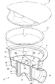
図2に示すように、排水トラップ3は、シンク2の底面に形成された開口にフランジ7を介して固着された有底円筒状のトラップ本体8を有しており、このトラップ本体8は、上方に開口されてシンク2からの排水が流入される開口部9を備えた水受椀部10と、水受椀部10よりも下方に配置されて上方の水受椀部10から流れてくる排水を溜める封水椀部11と、この封水椀部11の外周に環状に配置される外周流路部12と、から主に構成されている。
As shown in FIG. 2, the
図2及び図5に示すように、封水椀部11は、上方が開放されるお椀型、つまり有底円筒状を成しており、この封水椀部11の上端縁から溢れ出た水が周囲の外周流路部12に流れ落ちるようになっている。また、封水椀部11の底面には、中央が上方に突出された三角錐形状を成す山型部13が形成されている。
As shown in FIGS. 2 and 5, the sealed
尚、水受椀部10は円筒状に形成され、その内部には排水中に含まれる大きなゴミ等が封水椀部11内に入り込むことを防ぐ網かご14が取り付けられるようになっている。また、トラップ本体8の上部には、水受椀部10の上方の開口部9を蓋う蓋体15が着脱自在に取り付けられており、この蓋体15により網かご14内に捕捉されたゴミを隠すことができるようになっている。
The
図3に示すように、蓋体15は、上面に円盤状の板部材16が配置されており、この板部材16によって水受椀部10の上面開口を蓋うことができるようになっているとともに、板部材16の一部は切り欠かれており、この板部材16の切り欠かれた部位に略半円形状の皿部17が形成されている。この皿部17は、板部材16の中心から離れた位置に形成されるとともに、板部材16よりも下方に配置されており、板部材16と皿部17の間には、段部17aが形成されている。
As shown in FIG. 3, the
更に、図3に示す段部17aには、水受椀部10内に排水を流入させる流入孔18が縦向きに形成されている。尚、この流入孔18は、段部17aにおける中央部から離れた位置、すなわち外周縁部寄りに形成されており、該流入孔18から流入した排水が水受椀部10の内周面に沿うように流れるようになっている。皿部17には、下方に凹んで排水を案内できる本実施例における排水案内手段としての第1傾斜面17b(蓋体傾斜面)が形成されており、この第1傾斜面17bは、蓋体15の中心に向けて下方に傾斜し、かつ蓋体15の円周方向に向けて下方に傾斜しながら延設されており、第1傾斜面17bの傾斜の最下方は、段部17aに形成された流入孔18に繋がっている。尚、本実施例における第1傾斜面17bは、平面視で右回りの半円弧状を成している。
Further, in the
トラップ本体8の外周流路部12の下流側端部、つまりトラップ本体8の側方には、側方に開口して排水管4に接続される流出口19が形成されている。詳しくは、この流出口19の外周面には雄ネジ19aが形成されているとともに、該雄ネジ19aには袋ナット20が螺入されており、排水管4を流出口19に挿入した状態で、袋ナット20を流出口19の雄ネジ19aに螺合することで、流出口19に排水管4が取り付けられている。尚、流出口19と排水管4との間には、ゴムリング21が設けられ、排水管4が流出口19に水密に取り付けられるため、漏水が防止されている。
An
尚、図2及び図6に示すように、外周流路部12は、封水椀部11を平面視で右回りの螺旋状に取り囲むように形成されており、外周流路部12の底面は、円周方向に向かって下方に傾斜するように延設される本実施例における排水案内手段としての第3傾斜面12a(外周傾斜面)となっている。この第3傾斜面12aは、流出口19の一側方(図6中における流出口19の下側)から反対側の側方(図6中における流出口19の上側)に向けて環状に形成され、その最下方は流出口19に繋がっており、封水椀部11の上端縁から溢れ出た水は、外周流路部12に沿って円周方向に平面視で右回りに流下して流出口19から排出されるようになっている。
As shown in FIGS. 2 and 6, the outer peripheral
更に、排水トラップ3は、トラップ本体8に上方から取り付けられる円筒状の防臭筒22を備えている。この防臭筒22の下部には、封水椀部11に遊嵌される筒体23が形成されているとともに、防臭筒22の上部には、外方に向けて拡径する環状のフランジ部24が形成されている。フランジ部24の上面は、該防臭筒22の上面開口、すなわち水受椀部10内の排水をその下方の封水椀部11内に流入させるための中央の流入口25に導く水受面を構成している。フランジ部24の上面は流入口25の周囲に環状に形成されており、その外周側端面には雄ネジ24aが形成されている。尚、本実施例においては、フランジ部24の上面(水受面)が水受椀部10の底面を構成している。
Furthermore, the
つまり、図4に示すように、水受椀部10内の排水は、水受椀部10の底面中央に形成された流入口25から防臭筒22内に流入し、防臭筒22内を流下して該防臭筒22の下端開口から封水椀部11に流入する。また、流入口25には、棒状の摘み片26が流入口25の中心を通るように掛け渡されている。更に、トラップ本体8における水受椀部10と外周流路部12との間には、防臭筒22の雄ネジ24aが螺合される雌ネジ8aが形成されている。
That is, as shown in FIG. 4, the drainage in the
また、防臭筒22をトラップ本体8に取り付ける際には、防臭筒22をトラップ本体8に上方から挿入し、摘み片26を摘んで防臭筒22を回転させることで、フランジ部24の外周縁端面に形成された雄ネジ24aがトラップ本体8に形成された雌ネジ8aに螺合して取り付けられる。これにより、トラップ本体8の内部がフランジ部24により上下に区画され、流入口25のみを介してトラップ本体8の上下部、すなわち上方の水受椀部10と下方の封水椀部11及び外周流路部12とが連通されることになる。
Further, when the
また、フランジ部24の上面には、本実施例における排水案内手段としての第2傾斜面24b(水受傾斜面)が4つ形成されている。それぞれの第2傾斜面24bは、中心に向けて若干下方に傾斜し、かつ円周方向に向かって下方に傾くように延設されており、これらの第2傾斜面24bの傾きは、円周方向に対して同じ方向が低くなるように傾けられている。各々の第2傾斜面24bの間に形成された段部には、略垂直方向に立設され、平面視で外周縁から流入口25に向かって渦巻状に延びる本実施例における排水案内手段としての立設面24cが複数形成されている。尚、本実施例における立設面24cは、平面視で右回りの渦巻状を成している。
Further, four second
このように構成された排水トラップ3にあっては、図2に示すように、シンク2から流れてきた排水が封水椀部11に溜まるようになっているとともに、この封水椀部11内に上方から防臭筒22の筒体23が挿入され、筒体23の下端と封水椀部11の底面との間及び封水椀部11の内周と筒体23の外周との間に隙間、すなわち流路が形成されるように配置した状態でフランジ部24の雄ネジ24aを雌ネジ8aに螺合して封止することで、流入口25と流出口19とが封水椀部11を介してのみ連通することになるが、この封水椀部11内に所定レベル(例えば水面α)まで水が溜まることにより、筒体23の下端と封水椀部11の底面との間及び封水椀部11の内周と筒体23の外周との間に形成された隙間が水により塞がる、すなわち封水椀部11と防臭筒22とにより封水(封水椀部11内に溜まる排水)が形成されることにより、下水側、つまり流出口19側からの臭気や害虫等が屋内側に進入してきても、この封水椀部11を通過することができないようになっている。
In the
尚、防臭筒22の摘み片26の中央部には、本実施例における接触部材としての上方に突出する凸部26aと下方に突出する凸部26bが形成されている。上方側に突出する凸部26aは、網かご14の最下面に当接するようになっているとともに、下方側に突出する凸部26bは、封水椀部11に溜められた封水の水面αに接触するように形成されている。
In addition, the
このように防臭筒22に設けられた摘み片26に、網かご14の下面と封水の水面αの両方に接触できる凸部26a,26bが設けられることで、水が有する表面張力によって、網かご14の網目に停滞する水が凸部26a,26bを介して封水椀部11に溜められた封水に流れ落ちるようになり、網かご14の乾燥を早めることができ、網かご14におけるカビ等の発生を防ぐことができる。
In this manner, the
次に、排水がシンク2から排水トラップ3内に連続的に流入したときの排水の流れについて説明する。図1及び図3に示すように、シンク2から蓋体15の板部材16上に流れ込んだ排水は、板部材16の上面から皿部17に流れ込み、皿部17の第1傾斜面17bに案内されながら流入孔18から水受椀部10に流入する。ここで、排水が第1傾斜面17bを流れる際に、第1傾斜面17bが円周方向に向けて下方に傾いていることで、皿部17を流れる排水が、円周方向に右回りに回転するように流れる。
Next, the flow of drainage when drainage continuously flows from the
そして、排水が流入孔18から水受椀部10内に流れ込むことで、水受椀部10内において、円周方向に右回りの水流、すなわち渦流が発生することになる。このように、排水がトラップ本体8(水受椀部10)に流れ込む最初の開口部9にて、排水に円周方向に流れる渦流を発生させることで、蓋体15の流入孔18から水受椀部10に流れ込む水の勢いを利用して水受椀部10に渦流を効率よく発生させることができる。
Then, when the drainage flows into the
また、蓋体15における中心から離れた位置に排水の流れを円周方向に案内する皿部17が配置されているため、水流に発生する遠心力より、渦流に勢いを与えることができる。更に、蓋体15の段部17aに形成される流入孔18は、上下方向を向く段部17aの壁面に形成され、側方に開口しているため、該流入孔18から流入される排水は、水平方向に流れながら水受椀部10内に流入されるので、第1傾斜面17bによって円周方向に流れる排水の流れの勢いが弱まることなく水受椀部10内に流入され、水受椀部10内により勢いのある渦流を発生させることができる。
Moreover, since the
そして、水受椀部10内に流れ落ちて防臭筒22のフランジ部24の上面である水受面上を流れる排水は、図4に示すように、円周方向に向けて下方に傾斜する第2傾斜面24bの傾斜に沿って右回りに回転しながら流れ、更に、該第2傾斜面24bを流れる排水は、平面視で渦巻状になっている立設面24cにぶつかって中心に向けて案内され、フランジ部24の中央に形成された流入口25から下方の封水椀部11に流れ落ちるため、排水は右回りに回転する渦流となって封水椀部11に流れ込む。
And the waste water which flows down in the
このように本実施例においては、流入口25に排水が流れ込む直前のフランジ部24の上面において、第2傾斜面24b及び立設面24cによって、排水を右回りに回転させて渦流が発生されるので、流入する排水の水流により封水椀部11内に効率よく渦流を発生させることができる。
As described above, in this embodiment, on the upper surface of the
図5に示すように、防臭筒22の上面開口である流入口25から筒体23の内周面に沿うようにして封水椀部11に流れ込む排水は、右回りに回転する渦流となって流れ、この水流により封水椀部11内に溜まった水に渦流が発生するため、排水の流れが封水椀部11で停滞することなく、水流の勢いを保ったまま流れるようになる。さらに、この封水椀部11の渦流によって発生する遠心力により、排水に含まれるゴミが封水椀部11の内周面に向けて流動しやすくなり、筒体23の外周面との間の流路内を浮上して封水椀部11から溢れ出る排水とともに外周流路部12に流れ出すため、ゴミが封水椀部11の底面に滞留することが防止される。
As shown in FIG. 5, the waste water that flows from the
また、図2及び図5に示すように、封水椀部11の底面に、中央部が上方に突出された山型部13が形成されていることで、封水椀部11の底面の中央にゴミが溜まりにくくなるばかりか、封水椀部11の底面外周部寄り、すなわち封水椀部11の内周面と筒体23の外周面との間に形成される流路に向けてゴミが流動しやすくなるため、封水椀部11の底面の外周に溜まったゴミは、排水の水流により渦流が発生したときにその遠心力によって浮上し、封水椀部11から排水とともに外周流路部12に溢れ出やすくなる。尚、排水の流速を高めるため、筒体23の下端と封水椀部11の底面との間及び封水椀部11の内周と筒体23の外周との間に形成された隙間は5〜9mmであることが好ましい。
Moreover, as shown in FIG.2 and FIG.5, the center of the bottom face of the sealing
図2及び図6に示すように、封水椀部11から外周流路部12に溢れ出した排水は、外周流路部12に円周方向に向けて下方に傾くように形成された第3傾斜面12aに沿って円周方向に平面視で右回りに流れるようになる。このように封水椀部11から溢れ出る排水が渦流となって流れ出るようになるため、外周流路部12に排水中に含まれるゴミが溜まらないようになる。
As shown in FIG. 2 and FIG. 6, the drainage overflowing from the sealed
尚、排水がシンク2から多量、かつ連続的に流れてきた場合には、封水椀部11及び外周流路部12内の排水の水面が、封水椀部11の上端縁よりも上方になって流れる。そのときに外周流路部12を流れる排水が、第3傾斜面12aの傾斜に沿って平面視で右回りに流れると、封水椀部11内の排水も外周流路部12を流れる排水の水流に引きずられて平面視で右回りの渦流になる。よって、封水椀部11から排水が溢れ出る際においても封水椀部11内に渦流を効果的に発生させることができる。
In addition, when a large amount of drainage flows continuously from the
また、本実施例によれば、排水トラップ3に設けられた第1傾斜面17b、第2傾斜面、立設面24c、第3傾斜面12aの全ての排水案内手段が、平面視で同じ右回りに回転する渦流になるように排水を案内するので、排水トラップ3内を流れる排水の勢い(水流)を封水椀部11内で弱めることなく、スムーズに流出口19まで流出させることができる。更に本実施例では、右回りの渦流が発生するように排水案内手段が構成されているが、左回りの渦流が発生するように排水案内手段を構成してもよい。
Further, according to the present embodiment, all the drainage guiding means of the first
以上、本発明の実施例を図面により説明してきたが、具体的な構成はこれら実施例に限られるものではなく、本発明の要旨を逸脱しない範囲における変更や追加があっても本発明に含まれる。 Although the embodiments of the present invention have been described with reference to the drawings, the specific configuration is not limited to these embodiments, and modifications and additions within the scope of the present invention are included in the present invention. It is.
例えば、前記実施例における排水トラップ3では、排水案内手段として、蓋体15に形成された第1傾斜面17b(蓋体傾斜面)、水受椀部10の底面に形成された第2傾斜面24b(水受傾斜面)及び立設面24c、外周流路部12の底面に形成された第3傾斜面12b外周傾斜面が設けられていたが、これらのうちいずれか1つのみが形成されていてもよいし、組み合わせも種々に変更可能である。また、本発明における排水案内手段は、排水トラップ3に形成され、排水を案内することで該水流により渦流を発生させることができるものであれば、上記箇所に形成されていてもよい。
For example, in the
また、前記実施例では、排水案内手段としての立設面が、第2傾斜面24b同士の間に複数形成された段部に設けられた立設面24cとなっていたが、本発明はこれに限定されるものではなく、フランジ部24の上面に平面視で流入口25に向かって渦巻状に延びる凸条を形成し、この凸条における傾斜面側の側面を立設面として構成してもよいし、フランジ部24の上面に平面視で流入口25に向かって渦巻状に延びる凹条を形成し、この凹状における傾斜面側の側面を立設面として構成してもよく、このように渦巻状の凸条および凹条であってもフランジ部24の上面(水受面)を流れる排水に渦流を発生させることができる。
Moreover, in the said Example, although the standing surface as a drainage guide means was the standing
また、前記実施例では、網かごの最下面と封水椀部に溜められる封水の水面とに接触することができる接触部材は、防臭筒22の流入口25に掛け渡された摘み片26に形成された凸部26a,26bによって構成されていたが、本発明はこれに限定されるものではなく、防臭筒22とは別個に設けられた接触部材を構成してもよい。例えば、封水椀部11の底面に形成された山型部13の頂点をさらに上方まで延設して、山型部13を網かご14の最下面に接触させることで接触部材を構成してもよいし、網かご14の最下面に下方に延びる棒部材を固着させ、この棒部材の下端が封水椀部11の封水の水面と接触するようにして接触部材を構成してもよい。
Further, in the above embodiment, the contact member that can contact the lowermost surface of the mesh cage and the water surface of the sealed water stored in the sealed water bottle portion is the
1 キッチン台
2 シンク
3 排水トラップ
4 排水管
5 収納空間
6 扉
7 フランジ
8 トラップ本体
8a 雌ネジ
9 開口部
10 水受椀部
11 封水椀部
12 外周流路部
12a 第3傾斜面(外周傾斜面/排水案内手段)
13 山型部
14 網かご
15 蓋体
16 板部材
17 皿部
17a 段部
17b 第1傾斜面(蓋体傾斜面/排水案内手段)
18 流入孔
19 流出口
19a 雄ネジ
20 袋ナット
21 ゴムリング
22 防臭筒
23 筒体
24 フランジ部(水受面)
24a 雄ネジ
24b 第2傾斜面(水受傾斜面/排水案内手段)
24c 立設面(排水案内手段)
25 流入口
26 摘み片
26a,26b 凸部(接触部材)
DESCRIPTION OF SYMBOLS 1
13
18
24c Standing surface (drainage guide means)
25
Claims (4)
前記封水椀部内で一方向に回転する渦流が水流により発生するように排水を案内する排水案内手段を備え、前記排水案内手段は、前記流入口の周囲に形成される水受面上に、少なくとも円周方向に傾いて前記流入口に繋がるように形成された水受傾斜面である、ことを特徴とする排水トラップ。 An inflow port into which drainage is introduced, a sealed water trough portion for storing drainage water flowing in from the inflow port, and a deodorizing cylinder that has the inflow port and is disposed in the sealed water well portion to form sealed water, In a drainage trap comprising: an outlet for discharging drainage overflowing from the sealed water trough to the sewage side,
It comprises drainage guide means for guiding drainage so that a vortex rotating in one direction in the sealed water trough is generated by water flow , the drainage guide means on a water receiving surface formed around the inflow port, at least inclined circumferentially Ru formed water受傾slopes der so as to be connected to said inlet, drain trap, characterized in that.
Priority Applications (1)
| Application Number | Priority Date | Filing Date | Title |
|---|---|---|---|
| JP2005309757A JP4849664B2 (en) | 2005-10-25 | 2005-10-25 | Drain trap |
Applications Claiming Priority (1)
| Application Number | Priority Date | Filing Date | Title |
|---|---|---|---|
| JP2005309757A JP4849664B2 (en) | 2005-10-25 | 2005-10-25 | Drain trap |
Publications (2)
| Publication Number | Publication Date |
|---|---|
| JP2007120021A JP2007120021A (en) | 2007-05-17 |
| JP4849664B2 true JP4849664B2 (en) | 2012-01-11 |
Family
ID=38144141
Family Applications (1)
| Application Number | Title | Priority Date | Filing Date |
|---|---|---|---|
| JP2005309757A Active JP4849664B2 (en) | 2005-10-25 | 2005-10-25 | Drain trap |
Country Status (1)
| Country | Link |
|---|---|
| JP (1) | JP4849664B2 (en) |
Families Citing this family (5)
| Publication number | Priority date | Publication date | Assignee | Title |
|---|---|---|---|---|
| JP2007192024A (en) * | 2007-05-10 | 2007-08-02 | Isamu Tojikubo | Swirl drain port |
| JP2007198130A (en) * | 2007-05-21 | 2007-08-09 | Isamu Tojikubo | Swirl drain port |
| JP5156284B2 (en) * | 2007-06-29 | 2013-03-06 | クリナップ株式会社 | Drain outlet structure of sink |
| AT16002U1 (en) * | 2017-10-23 | 2018-10-15 | Alexander Haager | Drain valve for liquid container |
| GB2586614B (en) * | 2019-08-28 | 2024-02-28 | Smarti Env Ltd | A urinal outlet conduit |
Family Cites Families (6)
| Publication number | Priority date | Publication date | Assignee | Title |
|---|---|---|---|---|
| JPS6231177A (en) * | 1985-08-02 | 1987-02-10 | Nec Corp | Nonvolatile semiconductor memory device |
| JPH03113239U (en) * | 1990-03-06 | 1991-11-19 | ||
| JP2700732B2 (en) * | 1991-07-01 | 1998-01-21 | コスモケミカル株式会社 | Drain trap |
| JP2995530B2 (en) * | 1994-04-12 | 1999-12-27 | 東陶機器株式会社 | Drainage trap and floor drainage structure with drainage trap |
| JP2000273930A (en) * | 1999-03-24 | 2000-10-03 | Matsushita Electric Works Ltd | Drainage trap for sink |
| JP2005133314A (en) * | 2003-10-28 | 2005-05-26 | Matsushita Electric Works Ltd | Drainage trap |
-
2005
- 2005-10-25 JP JP2005309757A patent/JP4849664B2/en active Active
Also Published As
| Publication number | Publication date |
|---|---|
| JP2007120021A (en) | 2007-05-17 |
Similar Documents
| Publication | Publication Date | Title |
|---|---|---|
| JP2009203770A (en) | Hair catcher | |
| JP4849664B2 (en) | Drain trap | |
| JP2011021412A (en) | Draining perforated plate | |
| JP2011074610A (en) | Drain trap for urinal | |
| JP4837684B2 (en) | Hair catcher | |
| JP5703824B2 (en) | Drain trap | |
| JP7041593B2 (en) | Deodorant one | |
| JP2009167783A (en) | Hair catcher | |
| CN212561743U (en) | Confluence drainage device | |
| JP2009167589A (en) | Drain trap | |
| JP2009150111A (en) | Hair catcher and bathroom unit having hair catcher | |
| JP5319900B2 (en) | Hair catcher | |
| JP2007120022A (en) | Drain trap | |
| JP6326578B2 (en) | Drainage member | |
| JP5573000B2 (en) | Draining eye plate | |
| JP6072426B2 (en) | urinal | |
| KR100712963B1 (en) | Apparatus for preventing noise or counter inflow for draining pipe | |
| JP4994210B2 (en) | Drain trap | |
| JP2009185537A (en) | Hair catcher, and bathroom unit with the hair catcher | |
| JP3541290B2 (en) | Drain trap | |
| JP2009167769A (en) | Hair catcher | |
| JP5270881B2 (en) | Hair catcher | |
| JP6768169B1 (en) | Water discharge mechanism and water splash backflow prevention cover | |
| JP5717482B2 (en) | Drainage trap for urinal and non-flush urinal | |
| JP2009167591A (en) | Drain trap |
Legal Events
| Date | Code | Title | Description |
|---|---|---|---|
| A621 | Written request for application examination |
Free format text: JAPANESE INTERMEDIATE CODE: A621 Effective date: 20080722 |
|
| A977 | Report on retrieval |
Free format text: JAPANESE INTERMEDIATE CODE: A971007 Effective date: 20110218 |
|
| A131 | Notification of reasons for refusal |
Free format text: JAPANESE INTERMEDIATE CODE: A131 Effective date: 20110322 |
|
| A521 | Written amendment |
Free format text: JAPANESE INTERMEDIATE CODE: A523 Effective date: 20110523 |
|
| TRDD | Decision of grant or rejection written | ||
| A01 | Written decision to grant a patent or to grant a registration (utility model) |
Free format text: JAPANESE INTERMEDIATE CODE: A01 Effective date: 20111004 |
|
| A01 | Written decision to grant a patent or to grant a registration (utility model) |
Free format text: JAPANESE INTERMEDIATE CODE: A01 |
|
| RD04 | Notification of resignation of power of attorney |
Free format text: JAPANESE INTERMEDIATE CODE: A7424 Effective date: 20111005 |
|
| A61 | First payment of annual fees (during grant procedure) |
Free format text: JAPANESE INTERMEDIATE CODE: A61 Effective date: 20111017 |
|
| R150 | Certificate of patent or registration of utility model |
Ref document number: 4849664 Country of ref document: JP Free format text: JAPANESE INTERMEDIATE CODE: R150 Free format text: JAPANESE INTERMEDIATE CODE: R150 |
|
| FPAY | Renewal fee payment (event date is renewal date of database) |
Free format text: PAYMENT UNTIL: 20141028 Year of fee payment: 3 |
|
| R250 | Receipt of annual fees |
Free format text: JAPANESE INTERMEDIATE CODE: R250 |
|
| S111 | Request for change of ownership or part of ownership |
Free format text: JAPANESE INTERMEDIATE CODE: R313111 |
|
| R350 | Written notification of registration of transfer |
Free format text: JAPANESE INTERMEDIATE CODE: R350 |
|
| S111 | Request for change of ownership or part of ownership |
Free format text: JAPANESE INTERMEDIATE CODE: R313111 |
|
| R350 | Written notification of registration of transfer |
Free format text: JAPANESE INTERMEDIATE CODE: R350 |