JP4849178B2 - Mobile robot - Google Patents
Mobile robot Download PDFInfo
- Publication number
- JP4849178B2 JP4849178B2 JP2010057267A JP2010057267A JP4849178B2 JP 4849178 B2 JP4849178 B2 JP 4849178B2 JP 2010057267 A JP2010057267 A JP 2010057267A JP 2010057267 A JP2010057267 A JP 2010057267A JP 4849178 B2 JP4849178 B2 JP 4849178B2
- Authority
- JP
- Japan
- Prior art keywords
- trunk
- image
- robot
- camera
- connection site
- Prior art date
- Legal status (The legal status is an assumption and is not a legal conclusion. Google has not performed a legal analysis and makes no representation as to the accuracy of the status listed.)
- Expired - Fee Related
Links
Images


Landscapes
- Manipulator (AREA)
Description
本発明は、自律移動型ロボットに関する。特に、カメラを利用して周囲の環境を認識して移動するロボットに関する。 The present invention relates to an autonomous mobile robot. In particular, the present invention relates to a robot that moves by recognizing the surrounding environment using a camera.
体幹と、駆動機構を有する関節部を介して体幹に接続されている接続部位を備えている移動側ロボットが開発されている。この種のロボットのなかには、体幹に設けられている体幹側カメラで撮像された環境画像から環境地図を作成し、得られた環境地図を元に目的位置までの移動経路を計画するものがある。特許文献1では、ロボットの頭部に設けられているカメラで撮像し、撮像した画像から視差画像あるいは距離画像を計算し、計算した視差画像あるいは距離画像から平面パラメータを算出し、算出した平面パラメータから床を含む複数の平面抽出を行うことによって環境地図を作成し、作成した環境地図からロボットが移動可能な範囲を認識し、認識した範囲に基づいてロボットの移動経路を計画している。
A mobile robot has been developed that includes a trunk and a connection part that is connected to the trunk through a joint having a drive mechanism. Some robots of this type create an environment map from an environment image captured by a trunk-side camera provided on the trunk, and plan a movement route to a target position based on the obtained environment map. is there. In
駆動機構を有する関節部を介して体幹に接続されている接続部位を備えているロボットの場合、アームや脚などの接続部位の位置によっては、ロボットの体幹に設けられているカメラの視野の一部が接続部位によって遮られ、一部の周囲物体を撮像できないことがある。即ち、接続部位の背後に未知環境が存在することがある。
接続部位の背後に未知環境が存在すると、体幹の移動経路を計画することができなくなってしまう。あるいは、アームや脚などの接続部位の移動経路を計画することができなくなってしまう。特に、接続部位を目的位置に移動させる経路を計画する場合には、目的位置が未知環境にあるために、目的位置が認識できない事態が発生しやすい。例えば、異な る位置に配置されている2以上の体幹側カメラを利用して2以上の体幹側画像情報を得る ことができれば、両画像に撮像されている物体の奥行き情報が未知であっても、その物体 の移動型ロボットに対する相対的位置関係を計算することができる。しかしながら、接続 部位の影になっているために、いずれかの体幹側画像では撮像されていない周囲物体につ いては、位置を特定することができない。 In the case of a robot having a connection part connected to the trunk through a joint having a drive mechanism, the field of view of the camera provided on the trunk of the robot depends on the position of the connection part such as an arm or a leg. May be blocked by the connection site, and some surrounding objects may not be imaged. That is, an unknown environment may exist behind the connection site.
If there is an unknown environment behind the connection site, it will be impossible to plan a trunk movement route. Or it becomes impossible to plan the movement path | route of connection parts, such as an arm and a leg. In particular, when planning a route for moving a connection site to a target position, the target position is in an unknown environment, and a situation in which the target position cannot be recognized easily occurs. For example, if it is possible to obtain two or more trunk side image information by using two or more of the trunk side camera that is arranged at a position that different depth information of the object being imaged in both images was unknown However, the relative positional relationship of the object with respect to the mobile robot can be calculated. However, since that is a shadow of the connecting portion, the surrounding objects not imaged in one of the trunk side image information, it is impossible to identify the position.
現状技術では、未知環境が発生する毎に、体幹または接続部位を移動させて未知環境を撮像し、未知環境を未知環境でなくしてから移動経路を決定する処理を必要としている。
しかしながら、上記の処理には本来的には必要とされない動作を要するばかりでなく、体幹を連続的に移動させるロボットや、周囲物体が移動する環境にある場合には、対応することが難しい。
In the current technology, every time an unknown environment is generated, the trunk or the connected part is moved to image the unknown environment, and after the unknown environment is not an unknown environment, a process for determining the movement path is required.
However, the above-described processing not only requires an operation that is not essentially required, but is also difficult to cope with in a robot that continuously moves the trunk or in an environment where surrounding objects move.
本発明は、未知環境を発生させない移動型ロボットを実現することを目的とする。 An object of the present invention is to realize a mobile robot that does not generate an unknown environment.
本発明では、接続部位によって遮られて撮像できない範囲を撮像するために、接続部位にもカメラを用意する。接続部位にもカメラを用意すれば、接続部位によって撮像できないという事態の発生を防止することができる。 In the present invention, a camera is also prepared at the connection site in order to capture an area that is blocked by the connection site and cannot be imaged. If a camera is also prepared at the connection site, it is possible to prevent a situation where an image cannot be captured by the connection site .
例えば奥行き情報が既知であるような場合には、1枚の合成画像を得ること自体で有用な情報が得られる。奥行き情報が未知であれば、視点を変えて撮像した複数枚の画像情報を得、それらから周囲物体の位置を計算することが有用である。
本発明のロボットは、体幹と、駆動機構を有する関節部を介して体幹に接続されている接続部位と、体幹に設けられている2以上の体幹側カメラと、接続部位に設けられている接続部位側カメラと、2以上の体幹側カメラで撮像した2以上の体幹側画像から撮像範囲内に存在する物体の移動型ロボットに対する相対的位置関係を計算する第1計算手段と、体幹側カメラの少なくとも1つで撮像した体幹側画像と接続部位側カメラで撮像した接続部位側画像から撮像範囲内に存在する物体の移動型ロボットに対する相対的位置関係を計算する第2計算手段を備えている。第2計算手段は、接続部位を撮像している範囲が最も 少ない体幹側画像を選択して計算に用いる。本発明のロボットは、画像情報を処理することによって位置情報を計算する。合成画像を作成する必要は必ずしもない。For example, when depth information is known, useful information can be obtained by obtaining a single composite image itself. If the depth information is unknown, it is useful to obtain a plurality of pieces of image information picked up from different viewpoints and calculate the positions of surrounding objects from them.
The robot according to the present invention includes a trunk, a connection portion connected to the trunk via a joint having a drive mechanism, two or more trunk side cameras provided on the trunk, and a connection portion. First calculating means for calculating a relative positional relationship of an object existing in an imaging range with respect to a mobile robot from a connected site side camera and two or more trunk side images captured by two or more trunk side cameras And calculating a relative positional relationship of an object existing in the imaging range with respect to the mobile robot from the trunk side image captured by at least one of the trunk side cameras and the connection site side image captured by the connection site side camera. Bei Eteiru 2 calculation means. The second calculation means selects the trunk side image with the smallest range in which the connection site is imaged and uses it in the calculation. The robot of the present invention calculates position information by processing image information. It is not always necessary to create a composite image.
本発明のロボットでは、2つの体幹側カメラで撮影した体幹側画像の組み合わせて利用 するとともに、これに加えて、体幹側カメラの1つで撮像した体幹側画像と接続部位側カメラで撮像した接続部位側画像を組み合わせて利用する。これらも、視点を変えて撮像した2以上の画像情報であり、これらからも周囲物体の移動型ロボットに対する相対的位置関係を計算することができる。接続部位の影になって両方の体幹側カメラでは撮像できなくても、いずれか一方の体幹側カメラで撮像できれば、それと接続部位側画像情報を組み合わせて利用することによって、周囲物体の移動型ロボットに対する相対的位置関係を特定することができる。この場合、視点を変えて撮像した複数枚の合成画像が得られ、例え ば奥行き情報が未知な場合等に、撮像範囲内に存在する特徴点の3次元的位置を特定する といったことが可能となる。これにより、未知環境の範囲を狭めることができる。 In the robot according to the present invention, the trunk side image captured by the two trunk side cameras is used in combination , and in addition, the trunk side image captured by one of the trunk side cameras and the connection part side camera are used. The connection site side images imaged in the above are used in combination. These are also two or more pieces of image information picked up from different viewpoints, and the relative positional relationship of surrounding objects with respect to the mobile robot can also be calculated from these pieces of image information. Even if it cannot be captured by both trunk-side cameras due to the shadow of the connected part, if it can be captured by either one of the trunk-side cameras, it can be used to move surrounding objects by combining it with the connected part-side image information. The relative positional relationship with respect to the type robot can be specified. In this case, a plurality of composite images is obtained by imaging by changing the viewpoint, or the like when the depth information For example is unknown, it is possible such to identify the three-dimensional positions of feature points present in the imaging range Become. Thereby, the range of unknown environment can be narrowed.
なお、体幹側画像内において接続部位を撮像している範囲を特定する手段には、大きく Note that the means for identifying the range where the connection site is imaged in the trunk side image is largely
分けて2方式が可能である。一つの方式は、体幹側カメラに対する接続部位の位置関係(Two methods are possible separately. One method is the positional relationship of the connected part to the trunk side camera (
これはロボットに既知である)から接続部位が撮像されているはずの範囲を計算して求めThis is known to the robot) and is calculated by calculating the range where the connected part should be imaged.
る方式である。もう一つの方式は、体幹側画像を画像処理して接続部位の形状(これはロThis is a method. The other method is to perform image processing on the trunk side image and shape the connected part (this is
ボットに既知である)に相当する部分を抽出し、それから接続部位が撮像されている範囲The area corresponding to (known to the bot) is extracted, and then the connection site is imaged
を特定する方式である。第2計算手段によって選択される接続部位を撮像している範囲がThis is a method for identifying. The range in which the connection site selected by the second calculation means is imaged is
最も少ない体幹側画像は、いずれの方式によって選択されてもよい。The least number of trunk side images may be selected by any method.
上記のロボットは、その後の体幹または接続部位の移動経路を計算することができる。 The robot described above can calculate the subsequent movement path of the trunk or connection site.
未知環境を残さないようにするために無駄な動作が必要とされることがない。また周囲物In order not to leave an unknown environment, no unnecessary operation is required. Also surroundings
体が移動する環境にあっても、移動経路を時々刻々に決定することができる。Even in the environment where the body moves, the movement route can be determined from moment to moment.
本発明では、接続部位にカメラを設けることで、接続部位に第2の視覚認識部としての機能を付加している。この構成により、接続部位の影になって体幹側カメラでは撮像できない領域内に存在する周囲物体についても、その周囲物体の移動型ロボットに対する相対 的位置関係を特定することが可能となる。本発明によれば、未知環境の範囲を減少ないし無くすことができ、ロボットを安全に迅速に動作させることが可能となる。
In the present invention, by providing a camera at the connection site, a function as a second visual recognition unit is added to the connection site. With this configuration, it is possible to specify the relative positional relationship of the surrounding object with respect to the mobile robot even in the surrounding object that is in the shadow of the connection site and cannot be captured by the trunk-side camera . According to the present invention, the range of the unknown environment can be reduced or eliminated, and the robot can be operated safely and quickly.
最初に、以下に説明する実施例の主要な特徴を列記する。
(特徴1) ロボットは、体幹に走行機構(この実施例の場合は車輪であるが、脚リンクでもよい)を備えている。
(特徴2) ロボットは、環境地図から体幹の走行軌跡を計算する。
(特徴3) ロボットは、環境地図から接続部位の移動軌跡を計算する。
(特徴4) ロボットは、環境地図から体幹の走行軌跡と接続部位の移動軌跡を計算する。
(特徴5) ロボットは、関節角度制御装置や車輪回転数制御装置および位置情報検出装置により、ロボットの姿勢と各カメラの撮像方向を制御している。体幹側カメラの撮像方向は、体幹側カメラ撮像方向計算装置で計算され、接続部位側カメラの撮像方向は、接続部位側カメラ撮像方向計算装置で計算される。
(特徴6) ロボットは合成画像から得られた情報に基づき、移動経路を作成する。その経路に基づいて、前記関節角度制御装置や車輪回転数制御装置および位置情報検出装置がアクチュエータを制御し、体幹および/または接続部位を作成された移動経路に沿って移動させる。
(特徴7) ロボットは周囲環境の変化に対応して過去に作成した軌道に修正を加え、移動経路を変更する経路修正装置を備えている。
First, the main features of the embodiments described below are listed.
(Characteristic 1) The robot includes a traveling mechanism (a wheel in this embodiment, but a leg link may be used) in the trunk.
(Feature 2) The robot calculates the trunk trajectory from the environment map.
(Feature 3) The robot calculates the movement locus of the connected part from the environment map.
(Feature 4) The robot calculates the trunk trajectory and the connected part movement trajectory from the environment map.
(Feature 5) The robot controls the posture of the robot and the imaging direction of each camera by a joint angle control device, a wheel rotation speed control device, and a position information detection device. The imaging direction of the trunk side camera is calculated by the trunk side camera imaging direction calculation device, and the imaging direction of the connection site side camera is calculated by the connection site side camera imaging direction calculation device.
(Feature 6) The robot creates a movement path based on information obtained from the composite image. Based on the path, the joint angle control device, the wheel rotation speed control device, and the position information detection device control the actuator to move the trunk and / or the connection site along the created movement route.
(Characteristic 7) The robot includes a route correction device that corrects a trajectory created in the past in response to a change in the surrounding environment and changes the movement route.
図1に、本実施例のロボットの外観を示す。本実施例のロボット100は、体幹103と、肩関節203を介して体幹103に接続された1本の接続部位(アーム)104を有している。接続部位104は、2本以上が存在していてもよい。体幹103は、胴体200と、首関節202と、頭部201を備えており、頭部201に体幹側カメラ105が固定されている。体幹側カメラ105は、首関節202によって、胴体200に対する撮像方向を変えることができる。胴体200の下方には1対の車輪が配置されており、車輪206を利用して体幹103を移動させる。
接続部位104は、肩関節203と、肘関節204と、手首関節205を備えており、掌に側カメラ106が固定されている。肩関節203と、肘関節204と、手首関節205は能動機構を有しており、接続部位側カメラ106は、肩関節203と、肘関節204と、手首関節205によって、胴体200に対する撮像方向を変えることができる。また胴体200に対する接続部位側カメラ106のカメラ位置を変えることもできる。
このロボットは、作業環境内における頭部201の位置を計測する手段を備えており、体幹側カメラ105のカメラ位置と撮像方向を認識している。また、体幹103に対する接続部位側カメラ106のカメラ位置と撮像方向を認識している。
本実施例のロボット100は、車輪206を利用してスイッチパネル10に接近し、接続部位104を利用してスイッチパネル10の壁面に配置されているスイッチ群12a,12b・・を操作する。スイッチパネル10の壁面の位置は既知である。
FIG. 1 shows the appearance of the robot of this embodiment. The
The
This robot includes means for measuring the position of the
The
図2は、ロボット100の周囲を認識する機構101の概略を示す図である。本実施例のロボット100は、制御装置114を有している。制御装置114は、合成画像作成装置110を備えており、合成画像作成装置110は、体幹側カメラ105から体幹側画像情報を入力し、接続部位側カメラ106から接続部位側画像情報を入力し、体幹側カメラ位置撮像方向計算装置111から体幹側カメラ105の位置と撮像方向を入力し、接続部位側カメラ位置撮像方向計算装置109から接続部位側カメラ106の位置と撮像方向を入力し、体幹側画像情報と接続部位側画像情報から合成画像情報を作成し、作成した合成画像情報からその後の移動経路を作成し(移動経路作成装置113)、作成した移動経路情報にしたがって、車輪206と関節群を回転させるアクチュエータ群115を制御し、作成した移動経路に沿って、車輪206、頭部201、接続部位104を移動させる。ロボット100は、車輪206の回転数を検出する車輪回転数検出装置119と、各関節の関節角を検出する関節角検出装置117と、胴体200内に設置されていて胴体200の位置を検出する位置情報検出装置121を備えており、それらの装置で取得される情報が、体幹側カメラ位置撮像方向計算装置111と接続部位側カメラ位置撮像方向計算装置109に入力される。
ロボットは、位置と撮像方位が既知のカメラで撮影した画像情報から周囲の環境を認識して移動経路を作成する移動経路作成手段113を有しており、作成した移動経路に従って移動した後にカメラ位置と撮像方向を再計算し、その後に再度撮像する処理を繰り返しながら、自律的に移動する。
FIG. 2 is a diagram showing an outline of a
The robot has movement path creation means 113 for creating a movement path by recognizing the surrounding environment from image information captured by a camera whose position and imaging direction are known, and after moving along the created movement path, the camera position And re-calculate the imaging direction, and then move autonomously while repeating the process of imaging again.
図3に、ロボット100の視野図を示す。ロボット100の接続部位104が体幹側カメラ105の視野内に入ってしまうと、その後ろにある環境情報を得ることができない。具体的には、体幹側カメラ105から撮像する体幹側画像には、スイッチパネルの点Aおよび点Bは撮像されるのに対し、点Cおよび点Dは写らない。よって、点Cおよび点Dにおける周囲物体の情報が未知となり、環境状況の認識およびロボット100に対する周囲物体の相対的な位置関係の把握をすることができないが、本実施例では、接続部位側カメラ106を設けることで可視範囲が拡大され、点Cおよび点Dを含む、未知の環境を把握することができる。
FIG. 3 shows a view of the
図4および図5に、体幹側画像と接続部位側画像の例をそれぞれ示す。図4の体幹側画像では接続部位104の影に隠れて撮像されないパネルの表面が、図5の接続部位側画像では撮像されている。これは、頭部201と接続部位104の位置が関節角検出装置117により制御されており、体幹側カメラ105と接続部位側カメラ106の相対位置に応じて、接続部位側カメラ106の撮像方向が調節されることにより可能となる。接続部位側カメラ106の撮像方向は、体幹側カメラでは接続部位104の影に隠れて撮像できない方向を撮影するように調整される。
それぞれのカメラの倍率や画像サイズなどの差異に関する情報は、体幹側カメラ位置撮像方向計算装置111および接続部位側カメラ位置撮像方向計算装置109によって把握されており、合成時にはその情報に基づいた画像処理を行うため、それぞれの画像の撮像範囲が完全に一致しなくてもよい。例えば、体幹側カメラ105に対し接続部位側カメラ106はスイッチパネル10までの距離が異なっており、かつ接続部位104が頭部201に対して傾斜していることから、図5の接続部位側画像は図4の体幹側画像に比べて撮像されるスイッチパネル10の倍率が大きく、また傾いている。
4 and 5 show examples of the trunk side image and the connection part side image, respectively. In the trunk side image of FIG. 4, the surface of the panel which is hidden behind the shadow of the
Information regarding differences in magnification, image size, and the like of each camera is grasped by the trunk side camera position imaging
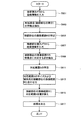
図6に、画像合成処理のフローチャートを示す。このとき、ロボット100とスイッチパネル10は図1に示すような位置関係にある。ロボット100の接続部位104は図4に示す位置にあり、同様の画像が体幹側カメラ105により撮像されている。ロボット100はスイッチパネル10のスイッチ12c(図1参照)を押圧するために、接続部位104を移動させようとしている。しかしながら、スイッチ12cは体幹側画像においては未知環境の範囲内にあるため、図6に示す合成画像作成処理を開始する。
ステップS601では、合成画像作成装置110に体幹側画像情報が入力される。ステップS603では、体幹側画像において未知環境となっている部分の特徴点Xnの抽出をする。図7に、ステップS603において抽出される体幹側画像の特徴点の一例を示す。ロボット100の接続部位104の形状は既知であることから、体幹側画像から接続部位を撮像している範囲(接続部位の撮像範囲)を特定することができる(第1特定手段)。図中の点X1からX6は、接続部位の撮像範囲を包含するように抽出された特徴点である。本実施例では、直線で結ぶことが可能な6個の特徴点を抽出しているが、接続部位の輪郭に沿って特徴点Xnをとればよい。ステップS605では、ステップS603において抽出された特徴点から、接続部位の撮像範囲R(背後の周囲物体情報が未知の範囲)を特定する。図7の特徴点X1からX6に囲まれた範囲が、近似的な接続部位の撮像範囲Rである。抽出する特徴点Xnの数を増やすことで、特徴点によって取り囲まれる範囲Rを接続部位の撮像範囲に正確に一致させることができる。
FIG. 6 shows a flowchart of the image composition process. At this time, the
In step S <b> 601, trunk-side image information is input to the composite
ステップS607では、合成画像作成装置110に接続部位側画像情報が入力される。
ステップS609では、ステップS607で入力された接続部位側画像情報から、体幹側画像の接続部位の撮像範囲Rの特徴点に対応する点Znを抽出する。図8に、ステップS609において抽出される接続部位側画像の特徴点Znの一例を示す。図8中の点Z1からZ6は、体幹側画像から抽出された特徴点X1からX6に対応する点である。
ステップS611では、ステップS609で抽出された特徴点Znから、接続部位側画像の対応範囲S(体幹側画像では未知情報である範囲)を特定する(第2特定手段)。
In step S <b> 607, the connected part side image information is input to the composite
In step S609, from the connection site side image information input in step S607, the extracting the Z n points corresponding to the feature points of the image scan range R of the connecting portion of the trunk side image. 8 shows an example of a feature point Z n connection site side image extracted in step S609. Points Z 1 to Z 6 in FIG. 8 are points corresponding to feature points X 1 to X 6 extracted from the trunk side image.
In step S611, from the feature point Z n extracted in step S609, (the trunk side image which range unknown information) corresponding range S of the connection portion-side image to identify the (second specifying means).
ステップS613では、接続部位側画像より得られた対応範囲Sを、体幹側画像より得られた接続部位の撮像範囲Rに適合するように、体幹側カメラと接続部位側カメラの入力画像に付加されている差異情報に基づき、サイズの調整、傾斜角の回転調整などの処理を行う。
ステップS615では、体幹側画像の接続部位の撮像範囲Rを、合成のための準備処理を終えた対応範囲Sに置き換える。その結果、ステップS617において、未知範囲のない合成画像が出力される。図9に、合成画像の一例を示す。破線で示されている接続部位の撮像範囲Rは対応範囲Sに置き換えられ、接続部位が撮像されていない合成画像を得ることができる。
In step S613, the corresponding range S obtained from the connected part side image is applied to the input images of the trunk side camera and the connected part side camera so as to match the imaging range R of the connected part obtained from the trunk side image. Based on the added difference information, processing such as size adjustment and tilt angle rotation adjustment is performed.
In step S615, the imaging range R of the connected part of the trunk side image is replaced with the corresponding range S for which the preparation process for synthesis has been completed. As a result, in step S617, a composite image without an unknown range is output. FIG. 9 shows an example of a composite image. The imaging range R of the connection site indicated by the broken line is replaced with the corresponding range S, and a composite image in which the connection site is not captured can be obtained.
本実施例は、複数の体幹側カメラを有していても良い。その場合は、それぞれの体幹側画像より接続部位の撮像範囲Rxを抽出し、それぞれの接続部位の撮像範囲Rxに対して接続部位側画像より対応範囲Sxを抽出し、接続部位の撮像範囲Rxを対応範囲Sxと置き換える。 The present embodiment may have a plurality of trunk side cameras. In that case, the imaging range R x of the connected part is extracted from each trunk side image, the corresponding range S x is extracted from the connected part side image for the imaging range R x of each connected part, The imaging range R x is replaced with the corresponding range S x .
図10に、3台の体幹側カメラから撮像された、3枚の体幹側画像TC1、TC2およびTC3を例示する。この体幹側画像TC1、TC2およびTC3はステップS601からステップS605の処理を経て、接続部位の撮像範囲R1、R2およびR3の特定を行っている。頭部に固定された3台の体幹側カメラの位置が異なるため、各画像の接続部位の撮像範囲の位置には差異がある。
図11に、上記の3台の体幹側カメラと連動して作動する接続部位側カメラが撮像した接続部位側画像ACを例示する。体幹側画像TC1、TC2およびTC3の接続部位の撮像範囲R1、R2およびR3を補うため、接続部位側画像ACはステップS607からステップS611の処理によって対応範囲S1、S2およびS3を特定する。
ステップS613からステップS617の処理により、体幹側画像TC1、TC2およびTC3の接続部位の撮像範囲R1、R2およびR3は、接続部位側画像ACの対応範囲S1、S2およびS3により置き換えられ、未知範囲のない体幹側カメラ画像が作成される。
FIG. 10 illustrates three trunk-side images TC 1 , TC 2, and TC 3 captured from three trunk-side cameras. The trunk side images TC 1 , TC 2 and TC 3 are subjected to the processing from step S601 to step S605, and the imaging ranges R 1 , R 2 and R 3 of the connected region are specified. Since the positions of the three trunk side cameras fixed to the head are different, there is a difference in the position of the imaging range of the connection part of each image.
FIG. 11 illustrates a connection part side image AC captured by the connection part side camera that operates in conjunction with the three trunk side cameras. In order to compensate for the imaging ranges R 1 , R 2, and R 3 of the connected parts of the trunk-side images TC 1 , TC 2, and TC 3 , the connected part-side image AC is subjected to the corresponding ranges S 1 , S, by the processing from step S 607 to step S 611. specifying the 2 and S 3.
By the processing from step S613 to step S617, the imaging ranges R 1 , R 2 and R 3 of the connection site of the trunk side images TC 1 , TC 2 and TC 3 are the corresponding ranges S 1 and S 2 of the connection site side image AC. and replaced by S 3, no trunk side camera images unknown range is created.
さらに、本実施例は、複数の接続部位側カメラを有していてもよい。この場合は、各体幹側画像の接続部位の撮像範囲Rに対して対応範囲Sが最も広範囲に抽出可能な接続部位側画像を利用するような判断装置を設けることが好ましい。 Further, the present embodiment may have a plurality of connection site side cameras. In this case, it is preferable to provide a determination device that uses the connected part side image that can extract the corresponding range S in the widest range with respect to the imaging range R of the connected part of each trunk side image.
本実施例はさらに、上記の方法で得られた合成画像を用いて、ロボット100に対する周囲物体の相対的な位置を計算することができる。ここでいうロボット100に対する周囲物体の相対的な位置は、物体の相対的位置座標をワールド座標系からロボットを中心とした座標系に変換して把握する。
In this embodiment, the relative position of the surrounding object with respect to the
実施例1と実施例2には、共通する部位があるため、共通する部位または装置については同一番号を付して重複説明を省略する。
図12は、ステレオカメラを用いたロボットの外観を示す図である。本実施例のロボット100は、体幹103と、肩関節203を介して体幹103に接続された一本の接続部位(アーム)104を有している。接続部位104は、2本以上が存在していてもよい。体幹103は、
胴体200と、首関節202と、頭部201を備えており、頭部201に体幹側カメラ105(a)および105(b)が固定されている。体幹側カメラ105(a)および105(b)は、首関節202によって、胴体200に対する撮像方向を変えることができる。胴体200の下方には1対の車輪206が配置されており、車輪206を利用して移動する。
接続部位104は、肩関節203と、肘関節204と、手首関節205を備えており、掌に接続部位側カメラ106が固定されている。肩関節203と、肘関節204と、手首関節205は能動機構を有しており、接続部位側カメラ106は、肩関節203と、肘関節204と、手首関節205によって、胴体200に対する撮像方向を変えることができる。また胴体200に対する接続部位側カメラ106のカメラ位置を変えることもできる。
このロボットは、作業環境内におえる頭部201の位置を計測する手段を備えており、体幹側カメラ105(a)および105(b)のカメラ位置と撮像方向を認識している。また、胴体200に対する接続部位側カメラ106のカメラ位置と撮像方向を認識している。
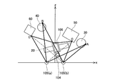
本実施例のロボット100は、周囲物体30,40,50,60を視覚により認識し、それらに衝突しない接続部位軌道を作成し、把持物20を空いたスペースに設置する。ロボット100の体幹側カメラ105(a)および105(b)は通常、ステレオカメラとして機能していて、図中の点A、B、C、Dは、ロボット100の視点である。
Since Example 1 and Example 2 have a common part, the same part or device is assigned the same number, and redundant description is omitted.
FIG. 12 is a diagram illustrating an appearance of a robot using a stereo camera. The
A
The
This robot includes means for measuring the position of the
The
図13は、本実施例のステレオカメラを用いたロボット100の周囲を認識する機構101の概略を示す図である。本実施例のロボット100は、制御装置114を有している。制御装置114は、画像情報処理装置116を備えており、画像情報処理装置116は体幹103に設けられている体幹側カメラ105(a)および105(b)から体幹側画像情報を入力し、接続部位104に設けられている接続部位側カメラ106から接続部位側画像情報を入力し、体幹側カメラ位置撮像方向計算装置111から体幹側カメラ105(a)および105(b)の位置と撮像方向を入力し、接続部位側カメラ位置撮像方向計算装置109から接続部位側カメラ106の位置と撮像方向を入力し、これらの画像情報およびカメラ位置と撮像方向に関する情報から、環境地図を作成し、環境地図記憶装置112に記憶する。その環境地図情報に基づき、その後の移動経路を作成し(移動経路作成装置113)、作成した移動経路情報にしたがって、車輪206と能動機構を有する関節を回転させるアクチュエータ群115を制御し、作成した移動経路に沿って、車輪206、頭部201、接続部位104を移動させる。ロボット100は、車輪206の回転数を検出する車輪回転数検出装置119と、各関節の関節角を検出する関節角検出装置123と、胴体200内に設置されていて胴体200の位置を検出する位置情報検出装置121を備えており、それらの装置で取得される情報が、体幹側カメラ位置撮像方向計算装置111と接続部位側カメラ位置撮像方向計算装置109に入力される。
ロボット100は、位置と撮像方位が既知のカメラで撮像した画像情報から周囲の環境を認識して移動経路を計算し、計算した移動経路に従って移動した後にカメラ位置と撮像方向を再計算し、その後に再度撮像するという処理を繰返しながら、自律的に移動する。
FIG. 13 is a diagram illustrating an outline of a
The
図14に、ロボット100の視野の鳥瞰図を示す。ロボット100の接続部位104とその把持物20が体幹側カメラ105(a)および105(b)の視野内に入ってしまうと、その後ろにある環境情報を得ることができない。
具体的には、図14の例において、点Aおよび点Bは、実線矢印で示すように体幹側カメラ105(a)および105(b)の両方より撮像可能であるため、体幹側画像からステレオ画像が生成可能となっており、ロボットの移動に合わせてその情報を時系列上連続して取得することができる。
それに対し、点Cおよび点Dに関しては、体幹側カメラだけでは下肢の移動位置もしくは接続部位の動作によって、それぞれの点の体幹側カメラ105(a)および105(b)を利用したステレオ視が不可能となり、その周囲についての環境情報を取得することができない。破線矢印は、接続部位あるいは把持物体が視線を遮るため、同じ特徴点を有する画像を撮像することができないことを示している。
ステレオカメラの場合、特に周囲物体の奥行きや高さなどの情報を必要とする場合は、複数の位置情報が既知のカメラを利用するか、あるいは1台のカメラが移動しながら撮像した場合のように、複数の画像から視差情報が得られることが必須となる。このため、点Cおよび点Dは両眼視ができないことから、点Cおよび点D付近の物体の位置関係を認識することができない。
FIG. 14 shows a bird's-eye view of the field of view of the
Specifically, in the example of FIG. 14, the point A and the point B can be captured by both the trunk side cameras 105 (a) and 105 (b) as indicated by solid arrows, and thus the trunk side image Thus, a stereo image can be generated, and the information can be continuously acquired in time series as the robot moves.
On the other hand, with respect to the points C and D, stereo viewing using the trunk-side cameras 105 (a) and 105 (b) at the respective points is performed only by the trunk-side camera, depending on the movement position of the lower limbs or the movement of the connection part. Cannot be obtained, and environmental information about the surroundings cannot be acquired. A broken line arrow indicates that an image having the same feature point cannot be captured because the connection site or the grasped object blocks the line of sight.
In the case of a stereo camera, especially when information such as the depth and height of surrounding objects is required, it is possible to use a camera whose position information is already known, or when a single camera is moving and capturing images. In addition, it is essential to obtain parallax information from a plurality of images. For this reason, since the points C and D cannot be viewed with both eyes, the positional relationship between the objects in the vicinity of the points C and D cannot be recognized.
このような場合、本実施例は、点Cおよび点Dの視点のように、視界を遮る物体の有無等により、体幹側カメラ105のいずれかがステレオカメラとして満足に機能することが困難な場合には、いずれかの体幹側カメラ105と接続部位側カメラ106を用いてステレオ画像を得ることができる。
具体的には、点Aおよび点Bの周辺など、接続部位104などの視野を遮る物体がない場合には体幹側カメラ105(a)および105(b)によりステレオ画像を取得し、周囲物体のロボット100に対する相対的な位置関係を計算することができる(第1計算手段)。その一方で、点Cのような場合には体幹側カメラ105(b)と接続部位側カメラ106により両眼視し、点Dの場合には体幹側カメラ105(a)と接続部位側カメラ106により両眼視をすることにより、周辺環境全域を認識するのに必要な情報を得、周囲物体のロボット100に対する相対的な位置関係を計算することができる(第2計算手段)。
In such a case, in the present embodiment, it is difficult for any of the
Specifically, when there is no object that obstructs the field of view, such as the
接続部位側カメラ106を使って両眼視をする場合、複数ある体幹側カメラのうち、どのカメラを使ってステレオ画像を取得するかは、接続部位104の撮像される範囲が最も少ない体幹側画像が取得される体幹側カメラを計算に用いるよう選択することができる。この選択は、画像情報処理装置116が判断する。
When binocular vision is performed using the connection
図15に、本実施例のロボットの動作概要を表わすフローチャートを示す。このとき、ロボット100は把持物20を把持しており、それを物体30,40,50および60に衝突しない接続部位軌道を作成し、把持物20を空いたスペースに設置する作業を実行したい。ロボット100の接続部位104は図14に示すような位置にあり、このような状態を表す画像が体幹側カメラ105(a)および105(b)の位置より撮像されている。接続部位104の軌道を作成するにあたって、物体50および物体60の一部が接続部位104および把持物20により未知となっているため、図15に示す画像情報処理を開始する。
ステップS500では、体幹側カメラ105(a)と105(b)および接続部位側カメラ106により撮像された複数の画像が画像情報処理装置116へ入力され、ステレオ画像が取得される。画像情報処理装置116は、体幹側画像の未知範囲の大きさにより、接続部位側画像を利用するかどうかを判断してもよく、接続部位104によって遮られ、未知範囲となる範囲がより少ない画像の組み合わせからステレオ画像を得る手段を有している。
FIG. 15 is a flowchart showing an outline of the operation of the robot of this embodiment. At this time, the
In step S500, a plurality of images captured by the trunk side cameras 105 (a) and 105 (b) and the connected
ステップS502では、ステップS500で選択され、取得されたステレオ画像に基づきロボット100の周囲物体の相対的な位置を計算する。画像データはワールド座標系からロボットを中心とする座標系に変換され、周囲物体の位置関係が計算され、ロボット100と周囲物体の相対的位置情報として出力される。例として、この相対的位置情報の取得には、視差画像や距離画像を用いてもよい。
このとき、体幹側画像どうしからステレオ画像情報を得る場合と、体幹側画像と接続部位側画像を利用してステレオ画像を得る場合とで、それぞれに第1計算手段および第2計算手段という、異なる計算手段を用意することが望ましい。体幹側カメラどうしは並行であるが、体幹側画像と接続部位側画像を利用した計算手段は、それぞれのカメラの相対位置が異なるため、例えばステレオ画像の平行化やハンド・アイ校正のような座標系の変換などが適用できる。
In step S502, the relative positions of the surrounding objects of the
At this time, when obtaining stereo image information from the trunk side images, and when obtaining a stereo image using the trunk side image and the connection part side image, they are referred to as first calculation means and second calculation means, respectively. It is desirable to prepare different calculation means. The trunk side cameras are parallel to each other, but the calculation means using the trunk side image and the connected part side image are different in relative positions of the respective cameras. For example, parallelization of stereo images and hand-eye calibration are performed. Various coordinate system transformations can be applied.
画像処理装置116において算出された相対的位置情報は、ステップS504において周囲物体の相対的位置を表わすデータとして構築され、環境地図記憶装置112に記憶される。環境地図とは、ロボット100が周囲物体の相対的位置を把握できるようなデータを指す。例えば、画像情報処理装置116において視差画像を算出するような場合は、この環境地図は画像視差空間(SDS空間 Spacial Disparity Space)により表わすことが可能である。SDS空間においては、点A、点B、点Cおよび点Dを有する周囲物体30,40,50,60は奥行きのある曲面として表れてくる。
The relative position information calculated in the
ステップS506では、環境地図情報に基づいてロボット100の移動経路を作成する。本実施例のロボット100は、周囲物体30,40,50,60を視覚により認識し、それらに衝突しない接続部位軌道を作成し、把持物20を空いたスペースに設置することを作業目的としているため、このような場合は環境地図情報より周囲物体が存在しない平面を検出し、そこへ把持物20を設置できるような接続部位の軌道を作成することが望ましい。作成された移動経路に沿って、ステップS508では、アクチュエータ115により実際の動作が実現される。
In step S506, the movement route of the
図16に、ロボット100の画像情報処理を表わすフローチャートを示す。図15のステップS500のスレテオ画像の取得方法は、複数の体幹側画像を使って取得する方法と、体幹側画像のいずれかと接続部位側画像を使って取得する方法の2手法が存在する。ステップS160では、体幹側カメラ105(a)と105(b)により撮像された複数の体幹側画像と、接続部位側カメラ106により撮像された接続部位側画像が画像情報処理装置116に入力される。ステップS162では、体幹側画像に接続部位104が撮像されているかを判断する。接続部位が撮像されていない場合(NOの場合)はステップS164に移行し、体幹側画像どうしからステレオ画像を取得し、第1計算手段を実行する。一方で、体幹側画像に接続部位が撮像されている場合は(YESの場合)はステップS166に進み、いずれかの体幹側画像と接続部位側画像からステレオ画像を取得し、第2計算手段を実行する。ステップS166で選択される体幹側画像は、接続部位の撮像されている範囲がより小さい方の体幹側画像である。
FIG. 16 is a flowchart showing image information processing of the
本実施例では、体幹および接続部位に合計3台のカメラを用いて周囲物体の3次元情報を得る場合を例示しているが、より多くのカメラを用いても良いし、1台の接続部位側カメラが移動することで連続して撮像するような手法を採っても良い。 In the present embodiment, the case where the three-dimensional information of the surrounding object is obtained using a total of three cameras for the trunk and the connection part is illustrated, but more cameras may be used, or one connection You may take the technique of imaging continuously, as a part side camera moves.
本実施例では静的な周囲物体を認識する場合について例示したが、移動経路作成装置113において作成された経路に沿って接続部位が動作を開始した後に、新たな障害物となる周囲物体が移動経路上に出現した場合や、周囲物体とロボットの位置が下肢の移動等により変化し、接続部位の軌道に修正が必要となった場合に対応することができない。
In this embodiment, the case of recognizing a static surrounding object is illustrated. However, after the connected part starts to move along the route created by the movement
図17に、動的な周囲物体に対応することができる形態を示す。このロボット機構101は、実施例2のロボット機構に、さらに接続部位の起動に修正を加える移動経路修正装置125を設けることで、一度発令された経路を適宜修正することができる。
また、適宜周辺環境のデータを更新することで、接続部位の動作と周囲の環境の変化を同時に、連続して認識し、それに応じて軌道を修正することができる。
FIG. 17 shows a form that can deal with a dynamic surrounding object. The
In addition, by appropriately updating the data of the surrounding environment, it is possible to simultaneously recognize the operation of the connected portion and the change of the surrounding environment at the same time and correct the trajectory accordingly.
以上、本発明の具体例を詳細に説明したが、これらは例示にすぎず、特許請求の範囲を限定するものではない。特許請求の範囲に記載の技術には、以上に例示した具体例を様々に変形、変更したものが含まれる。
例えば、アームだけでなく、脚などの複数の接続部位にそれぞれ、あるいは1本の接続部位の異なる部位に接続部位側カメラを回転可能に複数個装備すれば、撮像可能な範囲がより拡大される。
また、実施例2では体幹側カメラを主眼としたステレオ視について例示したが、複数の接続部位側カメラを用いてステレオ視を可能にし、体幹側カメラと接続部位側カメラそれぞれのステレオ画像処理装置を装備することで、さらに多様な用途に利用することができる。
本明細書または図面に説明した技術要素は、単独であるいは各種の組み合わせによって技術的有用性を発揮するものであり、出願時の請求項に記載の組み合わせに限定されるものではない。また、本明細書または図面に例示した技術は複数目的を同時に達成するものであり、そのうちの一つの目的を達成すること自体で技術的有用性を持つものである。
Specific examples of the present invention have been described in detail above, but these are merely examples and do not limit the scope of the claims. The technology described in the claims includes various modifications and changes of the specific examples illustrated above.
For example, if a plurality of connection site side cameras can be rotatably mounted not only on an arm but also on a plurality of connection sites such as legs, or on different sites of one connection site, the imageable range is further expanded. .
Further, in the second embodiment, the stereo view with the trunk side camera as the main object is illustrated, but the stereo view is made possible by using a plurality of connection part side cameras, and the stereo image processing of each of the trunk side camera and the connection part side camera is performed. Equipped with a device, it can be used for more diverse applications.
The technical elements described in this specification or the drawings exhibit technical usefulness alone or in various combinations, and are not limited to the combinations described in the claims at the time of filing. In addition, the technology illustrated in the present specification or the drawings achieves a plurality of objects at the same time, and has technical utility by achieving one of the objects.
100:ロボット
101:ロボット機構
103:体幹
104:接続部位(アーム)
105:体幹側カメラ
105(a):体幹側カメラ
105(b):体幹側カメラ
106:接続部位側カメラ
109:接続部位側カメラ位置撮像方向計算装置
110:合成画像作成装置
111:体幹側カメラ位置撮像方向計算装置
112:環境地図記憶装置
113:移動経路作成装置
114:制御装置
115:アクチュエータ群
116:画像処理装置
117:関節角検出装置
119:車輪回転数検出装置
121:位置情報検出装置
125:移動経路修正装置
200:胴体
201:頭部
202:首関節
203:肩関節
204:肘関節
205:手首関節
206:車輪
100: Robot 101: Robot mechanism 103: Trunk 104: Connection part (arm)
105: trunk-side camera 105 (a): trunk-side camera 105 (b): trunk-side camera 106: connection site-side camera 109: connection site-side camera position imaging direction calculation device 110: composite image creation device 111: body Stem side camera position imaging direction calculation device 112: Environmental map storage device 113: Movement path creation device 114: Control device 115: Actuator group 116: Image processing device 117: Joint angle detection device 119: Wheel rotation number detection device 121: Position information Detection device 125: Movement path correction device 200: Body 201: Head 202: Neck joint 203: Shoulder joint 204: Elbow joint 205: Wrist joint 206: Wheel
Claims (1)
駆動機構を有する関節部を介して体幹に接続されている接続部位と、
体幹に設けられている2以上の体幹側カメラと、
接続部位に設けられている接続部位側カメラと、
2以上の体幹側カメラで撮像した2以上の体幹側画像から、撮像範囲内に存在する物体の移動型ロボットに対する相対的な位置関係を計算する第1計算手段と、
体幹側カメラの少なくとも1つで撮像した体幹側画像と接続部位側カメラで撮像した接続部位側画像から、撮像範囲内に存在する物体の移動型ロボットに対する相対的な位置関係を計算する第2計算手段と、を備え、
前記第2計算手段は、接続部位を撮像している範囲が最も少ない体幹側画像を選択して計算に用いることを特徴とする移動型ロボット。The trunk,
A connection site connected to the trunk through a joint having a drive mechanism;
Two or more trunk side cameras provided on the trunk;
A connection site side camera provided in the connection site;
First calculation means for calculating a relative positional relationship of an object existing in the imaging range with respect to the mobile robot from two or more trunk-side images captured by two or more trunk-side cameras;
Calculating a relative positional relationship of an object existing in the imaging range with respect to the mobile robot from a trunk side image captured by at least one of the trunk side cameras and a connection site side image captured by the connection site side camera; 2 calculation means,
The mobile robot according to claim 2, wherein the second calculation means selects and uses a trunk-side image with the smallest range in which a connection site is imaged.
Priority Applications (1)
| Application Number | Priority Date | Filing Date | Title |
|---|---|---|---|
| JP2010057267A JP4849178B2 (en) | 2010-03-15 | 2010-03-15 | Mobile robot |
Applications Claiming Priority (1)
| Application Number | Priority Date | Filing Date | Title |
|---|---|---|---|
| JP2010057267A JP4849178B2 (en) | 2010-03-15 | 2010-03-15 | Mobile robot |
Related Parent Applications (1)
| Application Number | Title | Priority Date | Filing Date |
|---|---|---|---|
| JP2006041323A Division JP4506685B2 (en) | 2006-02-17 | 2006-02-17 | Mobile robot |
Publications (2)
| Publication Number | Publication Date |
|---|---|
| JP2010131751A JP2010131751A (en) | 2010-06-17 |
| JP4849178B2 true JP4849178B2 (en) | 2012-01-11 |
Family
ID=42343592
Family Applications (1)
| Application Number | Title | Priority Date | Filing Date |
|---|---|---|---|
| JP2010057267A Expired - Fee Related JP4849178B2 (en) | 2010-03-15 | 2010-03-15 | Mobile robot |
Country Status (1)
| Country | Link |
|---|---|
| JP (1) | JP4849178B2 (en) |
Families Citing this family (6)
| Publication number | Priority date | Publication date | Assignee | Title |
|---|---|---|---|---|
| JP5561037B2 (en) * | 2010-09-02 | 2014-07-30 | トヨタ自動車株式会社 | Robot and control method thereof |
| WO2014102995A1 (en) * | 2012-12-28 | 2014-07-03 | 株式会社日立製作所 | Monitoring system, method, and information-recording medium containing program |
| JP2014151377A (en) * | 2013-02-06 | 2014-08-25 | Seiko Epson Corp | Robot control method, robot control device, robot system, robot, and program |
| JP6704554B2 (en) * | 2018-03-29 | 2020-06-03 | 三菱電機株式会社 | Image processing apparatus, image processing method, and monitoring system |
| JP6816070B2 (en) * | 2018-08-24 | 2021-01-20 | ファナック株式会社 | Interference avoidance device and robot system |
| JP7028151B2 (en) * | 2018-12-14 | 2022-03-02 | トヨタ自動車株式会社 | Orbit generator |
Family Cites Families (7)
| Publication number | Priority date | Publication date | Assignee | Title |
|---|---|---|---|---|
| JPS57194895A (en) * | 1981-05-21 | 1982-11-30 | Tokyo Shibaura Electric Co | Monitoring device for manipulator |
| JPS6017509A (en) * | 1983-07-11 | 1985-01-29 | Furukawa Electric Co Ltd:The | Arm positioning method of hot-line robot for power distribution work |
| JP2960733B2 (en) * | 1989-07-27 | 1999-10-12 | 株式会社日立製作所 | Image display method, image display device, and remote operation device |
| JPH05126521A (en) * | 1991-11-08 | 1993-05-21 | Toshiba Corp | Position-measuring device for remote-controlled manipulator |
| JPH10230484A (en) * | 1997-02-24 | 1998-09-02 | Nec Corp | Machining work robot |
| JP2003080488A (en) * | 2001-09-05 | 2003-03-18 | National Institute Of Advanced Industrial & Technology | Monitoring device by remote operation |
| JP3994950B2 (en) * | 2003-09-19 | 2007-10-24 | ソニー株式会社 | Environment recognition apparatus and method, path planning apparatus and method, and robot apparatus |
-
2010
- 2010-03-15 JP JP2010057267A patent/JP4849178B2/en not_active Expired - Fee Related
Also Published As
| Publication number | Publication date |
|---|---|
| JP2010131751A (en) | 2010-06-17 |
Similar Documents
| Publication | Publication Date | Title |
|---|---|---|
| JP4506685B2 (en) | Mobile robot | |
| JP4961860B2 (en) | Robot apparatus and control method of robot apparatus | |
| JP4849178B2 (en) | Mobile robot | |
| JP3300682B2 (en) | Robot device with image processing function | |
| EP2682711B1 (en) | Apparatus and method for three-dimensional measurement and robot system comprising said apparatus | |
| JP6855492B2 (en) | Robot system, robot system control device, and robot system control method | |
| JP4665857B2 (en) | Mobile body capable of guiding arm and method for guiding arm | |
| JP2000293695A (en) | Picture processor | |
| JP6816070B2 (en) | Interference avoidance device and robot system | |
| JP2006224291A (en) | Robot system | |
| JP5698815B2 (en) | Information processing apparatus, information processing apparatus control method, and program | |
| JP7448884B2 (en) | Measurement system, measurement device, measurement method, and measurement program | |
| JP2686685B2 (en) | An active camera search system for object manipulation by robots | |
| JP2005205519A (en) | Robot hand device | |
| Heyer et al. | Camera Calibration for Reliable Object Manipulation in Care-Providing Robot FRIEND | |
| WO2024048491A1 (en) | Robot system, and method for controlling robot system | |
| JP7093881B1 (en) | System and automatic guided vehicle | |
| Fu et al. | Multi-waypoint visual homing in piecewise linear trajectory | |
| US20220388174A1 (en) | Autonomous and teleoperated sensor pointing on a mobile robot | |
| JP2012022600A (en) | Mask image creation system | |
| Shin et al. | Visual guidance system for remote-operation | |
| Mendiburu et al. | Obstacle avoidance for a robot manipulator based on visual feedback | |
| Mezouar | Optimal Camera Trajectory under visibility constraint in visual servoing: a variational approach | |
| Hornung et al. | A model-based approach for visual guided grasping with uncalibrated system components | |
| Seo et al. | Object-Based Visual Servoing for Autonomous Mobile Manipulators |
Legal Events
| Date | Code | Title | Description |
|---|---|---|---|
| A621 | Written request for application examination |
Free format text: JAPANESE INTERMEDIATE CODE: A621 Effective date: 20100315 |
|
| A521 | Written amendment |
Free format text: JAPANESE INTERMEDIATE CODE: A523 Effective date: 20100315 |
|
| TRDD | Decision of grant or rejection written | ||
| A01 | Written decision to grant a patent or to grant a registration (utility model) |
Free format text: JAPANESE INTERMEDIATE CODE: A01 Effective date: 20110920 |
|
| A01 | Written decision to grant a patent or to grant a registration (utility model) |
Free format text: JAPANESE INTERMEDIATE CODE: A01 |
|
| A977 | Report on retrieval |
Free format text: JAPANESE INTERMEDIATE CODE: A971007 Effective date: 20110922 |
|
| A61 | First payment of annual fees (during grant procedure) |
Free format text: JAPANESE INTERMEDIATE CODE: A61 Effective date: 20111003 |
|
| FPAY | Renewal fee payment (event date is renewal date of database) |
Free format text: PAYMENT UNTIL: 20141028 Year of fee payment: 3 |
|
| LAPS | Cancellation because of no payment of annual fees |