JP2014151377A - Robot control method, robot control device, robot system, robot, and program - Google Patents
Robot control method, robot control device, robot system, robot, and program Download PDFInfo
- Publication number
- JP2014151377A JP2014151377A JP2013021117A JP2013021117A JP2014151377A JP 2014151377 A JP2014151377 A JP 2014151377A JP 2013021117 A JP2013021117 A JP 2013021117A JP 2013021117 A JP2013021117 A JP 2013021117A JP 2014151377 A JP2014151377 A JP 2014151377A
- Authority
- JP
- Japan
- Prior art keywords
- end effector
- unit
- robot
- image
- control unit
- Prior art date
- Legal status (The legal status is an assumption and is not a legal conclusion. Google has not performed a legal analysis and makes no representation as to the accuracy of the status listed.)
- Withdrawn
Links
Images


Landscapes
- Manipulator (AREA)
Abstract
Description
本発明は、ロボット制御方法、ロボット制御装置、ロボットシステム、ロボット及びプログラムに関する。 The present invention relates to a robot control method, a robot control device, a robot system, a robot, and a program.
特許文献1には、ハンドが把持対象物を把持する直前あるいは直後において、前方カメラの撮像情報に基づいた制御から、側方カメラの撮像情報に基づいた制御に切り替えることが開示されている。 Patent Document 1 discloses switching from control based on imaging information of the front camera to control based on imaging information of the side camera immediately before or immediately after the hand grips the object to be gripped.
特許文献2には、ワークの位置と姿勢をカメラで計測し、計測結果に基づいてロボットをフィードバック制御し、カメラをワークの移動に追従させるビジュアルサーボ制御と、ビジュアルサーボ制御中にワークがカメラの視野から外れた場合に、認識したワークの最終位置を基にカメラの目標位置と移動速度を変更してワークを再補足する再補足制御と、を行うことが開示されている。 In Patent Document 2, the position and orientation of a workpiece are measured by a camera, the robot is feedback-controlled based on the measurement result, and the workpiece follows the movement of the workpiece. It is disclosed to perform re-supplementation control for re-supplementing a workpiece by changing the target position and moving speed of the camera based on the recognized final position of the workpiece when it is out of the field of view.
特許文献1に記載の発明は、ハンドが把持対象物を把持する直前あるいは直後で前方カメラから側方カメラにカメラを切り替えるだけであり、ハンドが把持対象物を把持する直前も直後もビジュアルサーボを行っている。しかしながら、特許文献1に記載の発明では、側方カメラが把持対象物等を見失った場合についての対応については記載されていない。 The invention described in Patent Document 1 only switches the camera from the front camera to the side camera immediately before or immediately after the hand grips the gripping object, and performs visual servoing immediately before or after the hand grips the gripping object. Is going. However, the invention described in Patent Document 1 does not describe how to deal with the case where the side camera loses sight of the object to be grasped.
特許文献2に記載の発明は、ワークを見失った場合にもワークを再補足することができる。しかしながら、特許文献2に記載の発明では、ワークの再補足を行ってもワークを認識できない場合についての対応については記載されていない。 The invention described in Patent Literature 2 can re-supplement a workpiece even when the workpiece is lost. However, in the invention described in Patent Document 2, there is no description about how to deal with the case where the workpiece cannot be recognized even if the workpiece is re-supplemented.
というのは、特許文献1、2に記載の発明は、ビジュアルサーボにより、対象物を把持する可動部の制御を行うものであるからである。すなわち、特許文献1、2に記載の発明では、ワークや把持対象物が画像から認識できない場合というのは、考慮されていない。 This is because the inventions described in Patent Documents 1 and 2 control a movable part that grips an object by visual servo. That is, in the inventions described in Patent Documents 1 and 2, the case where the workpiece or the grasped object cannot be recognized from the image is not considered.
しかしながら、ビジュアルサーボの作業中に、ワークや把持対象物が画像から認識できなくなる場合が考えられる。ワークや把持対象物が画像から認識できない場合には、画像に基づいた制御はできなくなる。したがって、この場合には、一般的には、可動部を止める(作業停止)しかない。 However, there may be a case where a work or a grasped object cannot be recognized from an image during visual servo work. If the workpiece or the gripping object cannot be recognized from the image, control based on the image cannot be performed. Therefore, in this case, generally, the movable part is only stopped (work stop).
なお、ワークや把持対象物が画像から認識できない場合に、ワークや把持対象物が最後に認識できた位置にあると推定して作業を続行することも考えられる。しかしながら、この場合には、ワークや把持対象物の推定位置と実際の位置とが異なることにより、作業中にワークや把持対象物が破壊される可能性がある。 If the workpiece or the gripping target cannot be recognized from the image, it may be assumed that the workpiece or the gripping target is at the position where the workpiece or the gripping target was last recognized and the operation can be continued. However, in this case, there is a possibility that the workpiece or the gripping object is destroyed during the operation because the estimated position of the workpiece or the gripping object is different from the actual position.
そこで、本発明は、エンドエフェクターが保持する対象物が画像から認識できない場合にも、安全に作業を継続することができるロボット制御方法、ロボット制御装置、ロボットシステム、ロボット及びプログラムを提供することを目的とする。 Therefore, the present invention provides a robot control method, a robot control device, a robot system, a robot, and a program that can continue work safely even when an object held by an end effector cannot be recognized from an image. Objective.
上記課題を解決するための第一の態様は、ロボット制御方法であって、第1の物体と、エンドエフェクターが保持する第2の物体とを含む画像を取得する第1のステップと、前記取得した画像から、前記第1の物体の表面の任意の位置である第1の位置及び前記第2の物体の表面の任意の位置である第2の位置を認識する第2のステップと、前記第2のステップで前記第1の位置及び前記第2の位置が認識できたか否かを判断する第3のステップと、前記第3のステップの判断結果に基づいて、異なる制御方法を用いて、前記第2の位置を前記第1の位置から前記第1の物体の内側へ所定の距離だけ離れた第3の位置に近づけるように、前記エンドエフェクターが先端に設けられた可動部を制御する第4のステップと、を有し、前記第4のステップは、前記第1の位置及び前記第2の位置が認識できたときは、前記第1の位置及び前記第2の位置の認識結果に基づいて前記可動部を制御し、前記第1の位置及び前記第2の位置の少なくとも一方が認識できなかったときは、前記可動部の先端に加わる力を取得し、当該取得した可動部の先端に加わる力に基づいて前記可動部を制御することを特徴とする。 A first aspect for solving the above problem is a robot control method, the first step of acquiring an image including a first object and a second object held by an end effector, and the acquisition A second step of recognizing a first position which is an arbitrary position on the surface of the first object and a second position which is an arbitrary position on the surface of the second object from the obtained image; The third step for determining whether or not the first position and the second position can be recognized in step 2 and the control method using different control methods based on the determination result of the third step, A fourth unit that controls the movable portion provided at the tip of the end effector so as to bring the second position closer to a third position that is a predetermined distance away from the first position to the inside of the first object; And the fourth step. When the first position and the second position can be recognized, the top controls the movable part based on the recognition result of the first position and the second position, and the first position When at least one of the position and the second position cannot be recognized, a force applied to the tip of the movable part is acquired, and the movable part is controlled based on the acquired force applied to the tip of the movable part. It is characterized by.
第一の態様によれば、画像から第1の物体の表面の任意の位置である第1の位置及び第2の物体の表面の任意の位置である第2の位置が認識できた場合には、第1の位置及び前記第2の位置の認識結果に基づいて可動部を制御し、画像から第1の位置又は第2の位置が認識できなかった場合は、可動部の先端に加わる力を取得し、当該取得した可動部の先端に加わる力に基づいて可動部を制御する。これにより、エンドエフェクターが保持する対象物が画像から認識できない場合にも、安全に作業を継続することができる。さらに、可動部の先端に加わる力に基づいて可動部を制御することで、画像から認識できない第3の位置に第2の位置を近づけるように可動部を制御することができる。 According to the first aspect, when the first position that is an arbitrary position on the surface of the first object and the second position that is an arbitrary position on the surface of the second object can be recognized from the image. If the movable part is controlled based on the recognition result of the first position and the second position, and the first position or the second position cannot be recognized from the image, the force applied to the tip of the movable part is applied. The movable part is acquired and controlled based on the force applied to the tip of the acquired movable part. Thereby, even when the object held by the end effector cannot be recognized from the image, the work can be safely continued. Furthermore, by controlling the movable portion based on the force applied to the tip of the movable portion, the movable portion can be controlled so that the second position is brought close to the third position that cannot be recognized from the image.
ここで、前記第4のステップでは、前記第1の位置及び前記第2の位置の少なくとも一方が認識できなかったときは、インピーダンス制御により前記可動部を制御してもよい。これにより、第1の物体、第2の物体や可動部に外力がかかる場合においても、第1の物体や第2の物体を破壊することを防止しつつ、確実に可動部を移動させることができる。 Here, in the fourth step, when at least one of the first position and the second position cannot be recognized, the movable part may be controlled by impedance control. Thereby, even when an external force is applied to the first object, the second object, and the movable part, the movable part can be reliably moved while preventing the first object and the second object from being destroyed. it can.
ここで、前記第4のステップでは、前記第1の位置及び前記第2の位置が認識できたときは、前記第2の位置が第1の量だけ移動するように前記可動部を制御し、前記第1の位置及び前記第2の位置の少なくとも一方が認識できなかったときは、前記第2の位置が前記第1の量より小さい第2の量だけ移動するように前記可動部を制御してもよい。これにより、対象物が画像から認識できない場合に、安全に可動部を移動させることができる。 Here, in the fourth step, when the first position and the second position are recognized, the movable unit is controlled so that the second position moves by a first amount, When at least one of the first position and the second position cannot be recognized, the movable unit is controlled so that the second position moves by a second amount smaller than the first amount. May be. Thereby, when an object cannot be recognized from an image, a movable part can be moved safely.
ここで、前記第3のステップにおいて、前記第1の位置及び前記第2の位置の少なくとも一方が認識できなかったときとは、前記第1の位置及び前記第2の位置の少なくとも一方が前記画像に含まれていない場合、前記第1の位置及び前記第2の位置の少なくとも一方が前記画像の任意の範囲内に含まれていない場合、前記第1の位置及び前記第2の位置の少なくとも一方が画像処理により認識できなかった場合、及び、前記第1の位置と前記第2の位置との位置関係が設定された範囲外である場合の少なくとも1つであってもよい。これにより、様々な状況に対応して作業を継続ことができる。 Here, in the third step, when at least one of the first position and the second position is not recognized, at least one of the first position and the second position is the image. If at least one of the first position and the second position is not included in an arbitrary range of the image, at least one of the first position and the second position May not be recognized by image processing, and may be at least one of a case where the positional relationship between the first position and the second position is outside a set range. Thereby, work can be continued corresponding to various situations.
ここで、前記第1のステップでは、前記画像を取得するステップは、前記第1の物体及び前記第2の物体を異なる方向から撮像した2枚の画像を取得し、前記第4のステップでは、前記2枚の画像の少なくとも1枚から前記第1の位置及び前記第2の位置の少なくとも一方が認識できなかった場合には、前記第1の位置及び前記第2の位置の少なくとも一方が認識できなかったときであるとして前記可動部を制御してもよい。これにより、より安全に作業を継続することができる。 Here, in the first step, the step of acquiring the image acquires two images obtained by capturing the first object and the second object from different directions, and in the fourth step, If at least one of the first position and the second position cannot be recognized from at least one of the two images, at least one of the first position and the second position can be recognized. You may control the said movable part as it is when it was not. Thereby, work can be continued more safely.
ここで、前記第4のステップでは、前記第2の位置から前記所定の距離だけ前記第2の物体の内側へ向かう方向へ移動させることにより前記第3の位置を算出し、当該算出された第3の位置へ前記第2の位置を近づけるように前記可動部を制御してもよい。これにより、第2の物体の内部にあって視認できない第3の位置へ可動部を制御することができる。 Here, in the fourth step, the third position is calculated by moving the second object in the direction toward the inside of the second object from the second position by the predetermined distance. The movable portion may be controlled to bring the second position closer to the third position. Thereby, a movable part can be controlled to the 3rd position which is inside the 2nd object and cannot be visually recognized.
ここで、前記第4のステップでは、前記第1の位置及び前記第2の位置が認識できたときは、前記認識結果から前記第2の位置を求め、前記第1の位置及び前記第2の位置の少なくとも一方が認識できなかったときは、前記可動部の移動量に基づいて前記第2の位置を求めてもよい。これにより、画像から第1の位置又は前記第2の位置が認識できなかった場合にも、第2の位置を求めることができる。 Here, in the fourth step, when the first position and the second position can be recognized, the second position is obtained from the recognition result, and the first position and the second position are obtained. When at least one of the positions cannot be recognized, the second position may be obtained based on the amount of movement of the movable part. Accordingly, even when the first position or the second position cannot be recognized from the image, the second position can be obtained.
上記課題を解決するための第二の態様は、ロボット制御装置であって、第1の物体と、エンドエフェクターが保持する第2の物体とを含む画像を取得する画像取得部と、前記取得した画像から、前記第1の物体の表面の任意の位置である第1の位置及び前記第2の物体の表面の任意の位置である第2の位置を認識する画像処理部と、前記第1の位置及び前記第2の位置の認識結果に基づいて、異なる制御方法を用いて、前記第2の位置を前記第1の位置から前記第1の物体の内側へ所定の距離だけ離れた第3の位置に近づけるように前記エンドエフェクターが先端に設けられた可動部を制御する制御部であって、前記第1の位置及び前記第2の位置が認識できたときは、前記第1の位置及び前記第2の位置の認識結果に基づいて、前記可動部を制御し、前記第1の位置及び前記第2の位置の少なくとも一方が認識できなかったときは、前記可動部の先端に加わる力を取得し、当該取得した可動部の先端に加わる力に基づいて前記可動部を制御する制御部と、を備えることを特徴とする。これにより、エンドエフェクターが保持する対象物が画像から認識できない場合にも、安全に作業を継続することができる。さらに、可動部の先端に加わる力に基づいて可動部を制御することで、画像から認識できない第3の位置に第2の位置を近づけるように可動部を制御することができる。 A second aspect for solving the above-described problem is a robot control device, the image acquisition unit acquiring an image including a first object and a second object held by the end effector, and the acquired An image processing unit for recognizing a first position, which is an arbitrary position on the surface of the first object, and a second position, which is an arbitrary position on the surface of the second object, from the image; Based on the position and the recognition result of the second position, the third position is moved away from the first position by a predetermined distance from the first position to the inside of the first object using different control methods. A control unit that controls a movable unit provided at a tip of the end effector so as to approach the position, and when the first position and the second position are recognized, the first position and the second position Based on the recognition result of the second position, the movable part Control, when at least one of the first position and the second position cannot be recognized, obtain a force applied to the tip of the movable part, and based on the obtained force applied to the tip of the movable part And a control unit that controls the movable unit. Thereby, even when the object held by the end effector cannot be recognized from the image, the work can be safely continued. Furthermore, by controlling the movable portion based on the force applied to the tip of the movable portion, the movable portion can be controlled so that the second position is brought close to the third position that cannot be recognized from the image.
上記課題を解決するための第三の態様は、ロボット制御装置であって、画像を取得する画像取得部と、前記画像から第1の物体及びエンドエフェクターが保持する第2の物体を認識する画像処理部と、前記画像処理部の認識結果に基づいて、前記第2の物体の位置を前記第1の物体の位置から所定の距離だけ離れた目標位置に近づけるように、前記エンドエフェクターの位置を制御する制御部と、を備え、前記制御部は、前記画像処理部が前記第1の物体及び前記第2の物体を認識できたときは、前記第1の物体の位置及び前記第2の物体の位置に基づいて、前記エンドエフェクターの位置を制御し、前記画像処理部が前記第1の物体及び前記第2の物体の少なくとも一方を認識できなかったときは、前記エンドエフェクターに加わる力を取得し、当該取得した力に基づいて前記エンドエフェクターの位置を制御することを特徴とする。これにより、エンドエフェクターが保持する対象物が画像から認識できない場合にも、安全に作業を継続することができる。 A third aspect for solving the above-described problem is a robot control apparatus, which is an image acquisition unit that acquires an image, and an image that recognizes a first object and a second object held by an end effector from the image. Based on the recognition result of the processing unit and the image processing unit, the position of the end effector is adjusted so as to bring the position of the second object closer to a target position separated from the position of the first object by a predetermined distance. A control unit that controls the position of the first object and the second object when the image processing unit can recognize the first object and the second object. The position of the end effector is controlled based on the position of the first effector, and when the image processing unit cannot recognize at least one of the first object and the second object, a force applied to the end effector is obtained. And, and controlling the position of the end effector on the basis of the acquired power. Thereby, even when the object held by the end effector cannot be recognized from the image, the work can be safely continued.
上記課題を解決するための第四の態様は、ロボットシステムであって、可動部及び前記可動部の先端に設けられたエンドエフェクターを有するロボットと、第1の物体と、前記可動部が保持する第2の物体とを含む画像を撮像する撮像部と、前記第1の物体の表面の任意の位置である第1の位置及び前記第2の物体の表面の任意の位置である第2の位置を認識する画像処理部と、前記第1の位置及び前記第2の位置の認識結果に基づいて、異なる制御方法を用いて、前記第2の位置を前記第1の位置から前記第1の物体の内側へ所定の距離だけ離れた第3の位置に近づけるように前記可動部を制御する制御部であって、前記第1の位置及び前記第2の位置が認識できたときは、前記第1の位置及び前記第2の位置の認識結果に基づいて、前記可動部を制御し、前記第1の位置及び前記第2の位置の少なくとも一方が認識できなかったときは、前記可動部の先端に加わる力を取得し、当該取得した可動部の先端に加わる力に基づいて前記可動部を制御する制御部と、を備えることを特徴とする。これにより、エンドエフェクターが保持する対象物が画像から認識できない場合にも、安全に作業を継続することができる。 A fourth aspect for solving the above-described problem is a robot system, which has a movable part and a robot having an end effector provided at the tip of the movable part, a first object, and the movable part holds the robot system. An imaging unit that captures an image including the second object, a first position that is an arbitrary position on the surface of the first object, and a second position that is an arbitrary position on the surface of the second object The second position is changed from the first position to the first object using a different control method based on the recognition result of the first position and the second position. A control unit that controls the movable unit so as to approach a third position that is a predetermined distance inward of the first position, and when the first position and the second position can be recognized, And the recognition result of the second position, When the moving part is controlled and at least one of the first position and the second position cannot be recognized, the force applied to the tip of the movable part is acquired, and the force applied to the acquired tip of the movable part And a control unit that controls the movable unit based on the above. Thereby, even when the object held by the end effector cannot be recognized from the image, the work can be safely continued.
ここで、前記撮像部は、前記第1の物体と前記第2の物体とを異なる方向から撮像する2つの撮像装置を有し、前記画像処理部は、前記2つの撮像装置のそれぞれで撮像された2枚の画像から前記第1の位置及び前記第2の位置を認識し、かつ、前記2つの撮像装置の少なくとも1つで撮像された画像から前記第1の位置及び前記第2の位置の少なくとも一方が認識できなかった場合は、前記第1の位置及び前記第2の位置の少なくとも一方が認識できなかった場合としてもよい。これにより、より安全に作業を継続することができる。 Here, the imaging unit includes two imaging devices that capture the first object and the second object from different directions, and the image processing unit is captured by each of the two imaging devices. The first position and the second position are recognized from two images, and the first position and the second position are detected from an image captured by at least one of the two imaging devices. When at least one of the first position and the second position cannot be recognized, it may be a case where at least one of the first position and the second position cannot be recognized. Thereby, work can be continued more safely.
上記課題を解決するための第五の態様は、ロボットシステムであって、エンドエフェクターを有するロボットと、画像を取得する画像取得部と、前記画像から第1の物体及び前記エンドエフェクターが保持する第2の物体を認識する画像処理部と、前記画像処理部の認識結果に基づいて、前記第2の物体の位置を前記第1の物体の位置から所定の距離だけ離れた目標位置に近づけるように、前記エンドエフェクターの位置を制御する制御部と、を備え、前記制御部は、前記画像処理部が前記第1の物体及び前記第2の物体を認識できたときは、前記第1の物体の位置及び前記第2の物体の位置に基づいて、前記エンドエフェクターの位置を制御し、前記画像処理部が前記第1の物体及び前記第2の物体の少なくとも一方を認識できなかったときは、前記エンドエフェクターに加わる力を取得し、当該取得した力に基づいて前記エンドエフェクターの位置を制御することを特徴とする。これにより、エンドエフェクターが保持する対象物が画像から認識できない場合にも、安全に作業を継続することができる。 According to a fifth aspect of the present invention, there is provided a robot system including a robot having an end effector, an image acquisition unit that acquires an image, a first object from the image, and a first object held by the end effector. Based on the recognition result of the image processing unit and the image processing unit that recognizes the second object, the position of the second object is brought close to a target position that is separated from the position of the first object by a predetermined distance. A control unit that controls the position of the end effector, and when the image processing unit can recognize the first object and the second object, the control unit controls the position of the first object. The position of the end effector is controlled based on the position and the position of the second object, and the image processing unit cannot recognize at least one of the first object and the second object Acquires the force applied to the end effector, and controlling the position of the end effector on the basis of the acquired power. Thereby, even when the object held by the end effector cannot be recognized from the image, the work can be safely continued.
上記課題を解決するための第六の態様は、ロボットシステムであって、第1の物体を保持するエンドエフェクターが先端に設けられた可動部を有するロボットと、レンズを有する撮像部と、前記撮像部による前記第1の物体及び前記第2の物体の撮像結果に基づいて前記第1の物体を第2の物体に近づけるように前記可動部を制御する制御部と、を備え、前記制御部は、前記レンズと前記第1の物体とを仮想的に結んだ線上に前記第2の物体、前記エンドエフェクター又は前記可動部がある場合には、前記エンドエフェクターに加わる力に基づいて前記可動部を制御することを特徴とする。これにより、レンズからみて第1の物体が他の物体と重なっている場合、すなわち画像上で第1の物体が他の物体に覆われている場合にも、安全に作業を継続することができる。 A sixth aspect for solving the above-described problem is a robot system, in which a robot having a movable part provided with an end effector for holding a first object at a tip, an imaging unit having a lens, and the imaging A control unit that controls the movable unit to bring the first object closer to the second object based on a result of imaging the first object and the second object by a unit, and the control unit includes: When there is the second object, the end effector or the movable part on a line virtually connecting the lens and the first object, the movable part is moved based on the force applied to the end effector. It is characterized by controlling. Thereby, even when the first object overlaps with another object as viewed from the lens, that is, when the first object is covered with another object on the image, the operation can be safely continued. .
上記課題を解決するための第七の態様は、ロボットシステムであって、第1の物体を保持するエンドエフェクターが先端に設けられた可動部を有するロボットと、レンズを有する撮像部と、前記撮像部による前記第1の物体及び前記第2の物体の撮像結果に基づいて前記第1の物体を第2の物体に近づけるように前記可動部を制御する制御部と、を備え、前記制御部は、前記レンズと前記第2の物体とを仮想的に結んだ線上に前記第1の物体、前記エンドエフェクター又は前記可動部がある場合には、前記エンドエフェクターに加わる力に基づいて前記可動部を制御することを特徴とする。これにより、レンズからみて第2の物体が他の物体と重なっている場合、すなわち画像上で第2の物体が他の物体に覆われている場合にも、安全に作業を継続することができる。 A seventh aspect for solving the above-described problem is a robot system, in which a robot having a movable part provided with an end effector holding a first object at a tip, an imaging unit having a lens, and the imaging A control unit that controls the movable unit to bring the first object closer to the second object based on a result of imaging the first object and the second object by a unit, and the control unit includes: When the first object, the end effector, or the movable part is on a line virtually connecting the lens and the second object, the movable part is moved based on the force applied to the end effector. It is characterized by controlling. Accordingly, even when the second object overlaps with another object as viewed from the lens, that is, when the second object is covered with another object on the image, the operation can be safely continued. .
ここで、前記制御部は、前記エンドエフェクターに加わる力に基づいて前記可動部を制御する場合、前記エンドエフェクターが受けた力の方向に、前記エンドエフェクターが受けた力に応じた移動速度及び安定性で前記エンドエフェクターを移動させてもよい。これにより、物体やロボットを破壊することを防止しつつ、ロボットに作業を行なわることができる。 Here, when the control unit controls the movable unit based on a force applied to the end effector, a moving speed and a stability according to the force received by the end effector in the direction of the force received by the end effector. The end effector may be moved by sex. Thereby, it is possible to work on the robot while preventing the object or the robot from being destroyed.
ここで、前記制御部は、前記エンドエフェクターに加わる力に基づいて前記可動部を制御する場合、前記エンドエフェクターを移動させる方向以外の力を前記エンドエフェクターが受けないように、前記エンドエフェクターが受けた力の方向に前記エンドエフェクターを移動させてもよい。これにより、物体やロボットを破壊することを防止しつつ、ロボットに作業を行なわることができる。 Here, when the control unit controls the movable unit based on the force applied to the end effector, the end effector receives the force other than the direction in which the end effector is moved. The end effector may be moved in the direction of the applied force. Thereby, it is possible to work on the robot while preventing the object or the robot from being destroyed.
上記課題を解決するための第八の態様は、ロボットシステムであって、撮像部と、第1の物体を保持するエンドエフェクターを有するロボットと、前記第1の物体を第2の物体に近づけるように前記エンドエフェクターの位置を制御する制御部と、を備え、前記制御部は、前記撮像部の撮像方向において前記第1の物体及び前記第2の物体が重なっていない場合には、前記撮像部の撮像結果に基づいて前記エンドエフェクターを制御し、前記撮像部の撮像方向において前記第1の物体及び前記第2の物体が重なっている場合には、前記エンドエフェクターに加わる力に基づいて前記エンドエフェクターを制御することを特徴とする。これにより、撮像部の撮像方向において第1の物体及び第2の物体が重なっている場合、すなわち画像上で第1の物体と第2の物体とが重なっている場合にも、安全に作業を継続することができる。 An eighth aspect for solving the above-described problem is a robot system, in which an imaging unit, a robot having an end effector that holds the first object, and the first object are brought close to the second object. A control unit that controls the position of the end effector, and the control unit, when the first object and the second object do not overlap in the imaging direction of the imaging unit, The end effector is controlled based on the imaging result of the imaging unit, and when the first object and the second object overlap in the imaging direction of the imaging unit, the end effector is controlled based on the force applied to the end effector. It controls the effector. Accordingly, even when the first object and the second object overlap in the imaging direction of the imaging unit, that is, when the first object and the second object overlap on the image, the work can be performed safely. Can continue.
ここで、前記制御部は、前記エンドエフェクターに加わる力に基づいて前記可動部を制御する場合、前記エンドエフェクターが受けた力の方向に、前記エンドエフェクターが受けた力に応じた移動速度及び安定性で前記エンドエフェクターを移動させてもよい。これにより、物体やロボットを破壊することを防止しつつ、ロボットに作業を行なわることができる。 Here, when the control unit controls the movable unit based on a force applied to the end effector, a moving speed and a stability according to the force received by the end effector in the direction of the force received by the end effector. The end effector may be moved by sex. Thereby, it is possible to work on the robot while preventing the object or the robot from being destroyed.
ここで、前記制御部は、前記エンドエフェクターに加わる力に基づいて前記可動部を制御する場合、前記エンドエフェクターを移動させる方向以外の力を前記エンドエフェクターが受けないように、前記エンドエフェクターが受けた力の方向に前記エンドエフェクターを移動させてもよい。これにより、物体やロボットを破壊することを防止しつつ、ロボットに作業を行なわることができる。 Here, when the control unit controls the movable unit based on the force applied to the end effector, the end effector receives the force other than the direction in which the end effector is moved. The end effector may be moved in the direction of the applied force. Thereby, it is possible to work on the robot while preventing the object or the robot from being destroyed.
上記課題を解決するための第九の態様は、ロボットシステムであって、撮像部と、第1の物体を保持するエンドエフェクターを有するロボットと、を備え、前記撮像部の撮像方向において、前記第1の物体及び前記第2の物体が重なっていない場合、前記撮像部の撮像結果に基づいて前記第1の物体を第2の物体に近づける工程と、前記撮像部の撮像方向において、前記第1の物体及び前記第2の物体が重なっている場合、前記エンドエフェクターに加わる力に基づいて前記エンドエフェクターの位置を制御する工程と、を有することを特徴とする。これにより、撮像部の撮像方向において第1の物体及び第2の物体が重なっている場合、すなわち画像上で第1の物体と第2の物体とが重なっている場合にも、安全に作業を継続することができる。 According to a ninth aspect of the present invention, there is provided a robot system comprising: an imaging unit; and a robot having an end effector that holds the first object. When the first object and the second object do not overlap, the first object is moved closer to the second object based on the imaging result of the imaging unit, and the first imaging object is in the imaging direction of the imaging unit. And a step of controlling the position of the end effector based on a force applied to the end effector when the object and the second object overlap each other. Accordingly, even when the first object and the second object overlap in the imaging direction of the imaging unit, that is, when the first object and the second object overlap on the image, the work can be performed safely. Can continue.
上記課題を解決するための第十の態様は、ロボットであって、可動部と、前記可動部の先端に設けられたエンドエフェクターと、第1の物体と、前記エンドエフェクターが保持する第2の物体とを含む画像を取得する画像取得部と、前記第1の物体の表面の任意の位置である第1の位置及び前記第2の物体の表面の任意の位置である第2の位置を認識する画像処理部と、前記第1の位置及び前記第2の位置の認識結果に基づいて、異なる制御方法を用いて、前記第2の位置を前記第1の位置から前記第1の物体の内側へ所定の距離だけ離れた第3の位置に近づけるように前記可動部を制御する制御部であって、前記第1の位置及び前記第2の位置が認識できたときは、前記第1の位置及び前記第2の位置の認識結果に基づいて、前記可動部を制御し、前記第1の位置及び前記第2の位置の少なくとも一方が認識できなかったときは、前記可動部の先端に加わる力を取得し、当該取得した可動部の先端に加わる力に基づいて前記可動部を制御する制御部と、を備えることを特徴とする。これにより、エンドエフェクターが保持する対象物が画像から認識できない場合にも、安全に作業を継続することができる。 A tenth aspect for solving the above problem is a robot, which is a movable part, an end effector provided at a tip of the movable part, a first object, and a second object held by the end effector. An image acquisition unit that acquires an image including an object, and a first position that is an arbitrary position on the surface of the first object and a second position that is an arbitrary position on the surface of the second object The second position is moved from the first position to the inside of the first object using a different control method based on the recognition result of the image processing unit and the first position and the second position. A control unit that controls the movable unit to approach a third position separated by a predetermined distance from the first position when the first position and the second position can be recognized. And based on the recognition result of the second position, If at least one of the first position and the second position cannot be recognized, a force applied to the tip of the movable part is acquired, and based on the acquired force applied to the tip of the movable part And a control unit that controls the movable unit. Thereby, even when the object held by the end effector cannot be recognized from the image, the work can be safely continued.
ここで、前記可動部を2つ備え、前記2つの可動部のうちの1つが前記第2の物体を保持し、前記2つの可動部のうちの他の1つが前記第1の物体を保持してもよい。これにより、2つの可動部のそれぞれが保持する2つの対象物を組み合わせる等の作業を、エンドエフェクターが保持する対象物が画像から認識できない場合にも、安全に作業を継続することができる。 Here, two movable parts are provided, one of the two movable parts holds the second object, and the other one of the two movable parts holds the first object. May be. As a result, work such as combining two objects held by each of the two movable parts can be safely continued even when the object held by the end effector cannot be recognized from the image.
上記課題を解決するための第十一の態様は、ロボットであって、エンドエフェクターと、画像を取得する画像取得部と、前記画像から第1の物体及び前記エンドエフェクターが保持する第2の物体を認識する画像処理部と、前記画像処理部の認識結果に基づいて、前記第2の物体の位置を前記第1の物体の位置から所定の距離だけ離れた目標位置に近づけるように、前記エンドエフェクターの位置を制御する制御部と、を備え、前記制御部は、前記画像処理部が前記第1の物体及び前記第2の物体を認識できたときは、前記第1の物体の位置及び前記第2の物体の位置に基づいて、前記エンドエフェクターの位置を制御し、前記画像処理部が前記第1の物体及び前記第2の物体の少なくとも一方を認識できなかったときは、前記エンドエフェクターに加わる力を取得し、当該取得した力に基づいて前記エンドエフェクターの位置を制御することを特徴とする。これにより、エンドエフェクターが保持する対象物が画像から認識できない場合にも、安全に作業を継続することができる。 An eleventh aspect for solving the above problem is a robot, which is an end effector, an image acquisition unit that acquires an image, a first object from the image, and a second object held by the end effector. And the image processing unit for recognizing the position of the second object based on the recognition result of the image processing unit so as to bring the position of the second object closer to a target position separated from the position of the first object by a predetermined distance. A control unit that controls the position of the effector, and when the image processing unit is able to recognize the first object and the second object, the control unit and the position of the first object Based on the position of the second object, the position of the end effector is controlled, and when the image processing unit cannot recognize at least one of the first object and the second object, the end effector. Gets the force applied to the coater, and controlling the position of the end effector on the basis of the acquired power. Thereby, even when the object held by the end effector cannot be recognized from the image, the work can be safely continued.
上記課題を解決するための第十二の態様は、ロボットであって、レンズを有する撮像部と、第1の物体を保持するエンドエフェクターが先端に設けられた可動部と、前記撮像部による前記第1の物体及び前記第2の物体の撮像結果に基づいて前記第1の物体を第2の物体に近づけるように前記可動部を制御する制御部と、を備え、前記制御部は、前記レンズと前記第1の物体とを仮想的に結んだ線上に前記第2の物体、前記エンドエフェクター又は前記可動部がある場合には、前記エンドエフェクターに加わる力に基づいて前記可動部を制御することを特徴とする。これにより、レンズから見て第1の物体が他の物体と重なっている、すなわち画像上で第1の物体が他の物体に覆われている場合にも、安全に作業を継続することができる。 A twelfth aspect for solving the above-described problem is a robot, in which an imaging unit having a lens, a movable unit having an end effector for holding a first object provided at a tip, and the imaging unit A control unit that controls the movable unit so as to bring the first object closer to the second object based on the imaging result of the first object and the second object, and the control unit includes the lens When the second object, the end effector or the movable part is on a line virtually connecting the first object and the first object, the movable part is controlled based on a force applied to the end effector. It is characterized by. Thereby, even when the first object overlaps with another object as viewed from the lens, that is, the first object is covered with the other object on the image, the operation can be safely continued. .
上記課題を解決するための第十三の態様は、ロボットであって、レンズを有する撮像部と、第1の物体を保持するエンドエフェクターが先端に設けられた可動部と、前記撮像部による前記第1の物体及び前記第2の物体の撮像結果に基づいて前記第1の物体を第2の物体に近づけるように前記可動部を制御する制御部と、を備え、前記制御部は、前記レンズと前記第2の物体とを仮想的に結んだ線上に前記第1の物体、前記エンドエフェクター又は前記可動部がある場合には、前記エンドエフェクターに加わる力に基づいて前記可動部を制御することを特徴とする。これにより、レンズから見て第2の物体が他の物体と重なっている、すなわち画像上で第2の物体が他の物体に覆われている場合にも、安全に作業を継続することができる。 A thirteenth aspect for solving the above problem is a robot, which is an imaging unit having a lens, a movable unit provided with an end effector holding a first object at a tip, and the imaging unit A control unit that controls the movable unit so as to bring the first object closer to the second object based on the imaging result of the first object and the second object, and the control unit includes the lens When the first object, the end effector, or the movable part is on a line that virtually connects the second object and the second object, the movable part is controlled based on a force applied to the end effector. It is characterized by. Thereby, even when the second object overlaps with another object as viewed from the lens, that is, the second object is covered with the other object on the image, the operation can be safely continued. .
ここで、前記制御部は、前記エンドエフェクターに加わる力に基づいて前記可動部を制御する場合、前記エンドエフェクターが受けた力の方向に、前記エンドエフェクターが受けた力に応じた移動速度及び安定性で前記エンドエフェクターを移動させてもよい。これにより、物体やロボットを破壊することを防止しつつ、ロボットに作業を行なわることができる。 Here, when the control unit controls the movable unit based on a force applied to the end effector, a moving speed and a stability according to the force received by the end effector in the direction of the force received by the end effector. The end effector may be moved by sex. Thereby, it is possible to work on the robot while preventing the object or the robot from being destroyed.
ここで、前記制御部は、前記エンドエフェクターに加わる力に基づいて前記可動部を制御する場合、前記エンドエフェクターを移動させる方向以外の力を前記エンドエフェクターが受けないように、前記エンドエフェクターが受けた力の方向に前記エンドエフェクターを移動させてもよい。これにより、物体やロボットを破壊することを防止しつつ、ロボットに作業を行なわることができる。 Here, when the control unit controls the movable unit based on the force applied to the end effector, the end effector receives the force other than the direction in which the end effector is moved. The end effector may be moved in the direction of the applied force. Thereby, it is possible to work on the robot while preventing the object or the robot from being destroyed.
上記課題を解決するための第十四の態様は、ロボットであって、撮像部が撮像した画像を取得する取得部と、第1の物体を保持するエンドエフェクターと、前記第1の物体を第2の物体に近づけるように前記エンドエフェクターの位置を制御する制御部と、を備え、前記制御部は、前記撮像部の撮像方向において前記第1の物体及び前記第2の物体が重なっていない場合には、前記取得した画像に基づいて前記エンドエフェクターを制御し、前記撮像部の撮像方向において前記第1の物体及び前記第2の物体が重なっている場合には、前記エンドエフェクターに加わる力に基づいて前記エンドエフェクターを制御することを特徴とする。これにより、撮像部の撮像方向において第1の物体及び第2の物体が重なっている場合、すなわち画像上で第1の物体と第2の物体とが重なっている場合にも、安全に作業を継続することができる。 A fourteenth aspect for solving the above problem is a robot, in which an acquisition unit that acquires an image captured by an imaging unit, an end effector that holds a first object, and a first object that A control unit that controls the position of the end effector so as to approach the second object, and the control unit is configured such that the first object and the second object do not overlap in the imaging direction of the imaging unit. The end effector is controlled based on the acquired image, and when the first object and the second object overlap in the imaging direction of the imaging unit, the force applied to the end effector is The end effector is controlled based on the above. Accordingly, even when the first object and the second object overlap in the imaging direction of the imaging unit, that is, when the first object and the second object overlap on the image, the work can be performed safely. Can continue.
ここで、前記制御部は、前記エンドエフェクターに加わる力に基づいて前記可動部を制御する場合、前記エンドエフェクターが受けた力の方向に、前記エンドエフェクターが受けた力に応じた移動速度及び安定性で前記エンドエフェクターを移動させてもよい。これにより、物体やロボットを破壊することを防止しつつ、ロボットに作業を行なわることができる。 Here, when the control unit controls the movable unit based on a force applied to the end effector, a moving speed and a stability according to the force received by the end effector in the direction of the force received by the end effector. The end effector may be moved by sex. Thereby, it is possible to work on the robot while preventing the object or the robot from being destroyed.
ここで、前記制御部は、前記エンドエフェクターに加わる力に基づいて前記可動部を制御する場合、前記エンドエフェクターを移動させる方向以外の力を前記エンドエフェクターが受けないように、前記エンドエフェクターが受けた力の方向に前記エンドエフェクターを移動させてもよい。これにより、物体やロボットを破壊することを防止しつつ、ロボットに作業を行なわることができる。 Here, when the control unit controls the movable unit based on the force applied to the end effector, the end effector receives the force other than the direction in which the end effector is moved. The end effector may be moved in the direction of the applied force. Thereby, it is possible to work on the robot while preventing the object or the robot from being destroyed.
上記課題を解決するための第十五の態様は、ロボットであって、撮像部と、第1の物体を保持するエンドエフェクターと、を備え、前記撮像部の撮像方向において、前記第1の物体及び前記第2の物体が重なっていない場合、前記撮像部の撮像結果に基づいて前記第1の物体を第2の物体に近づける工程と、前記撮像部の撮像方向において、前記第1の物体及び前記第2の物体が重なっている場合、前記エンドエフェクターに加わる力に基づいて前記エンドエフェクターの位置を制御する工程と、を有することを特徴とする。これにより、撮像部の撮像方向において第1の物体及び第2の物体が重なっている場合、すなわち画像上で第1の物体と第2の物体とが重なっている場合にも、安全に作業を継続することができる。 A fifteenth aspect for solving the above problem is a robot, comprising: an imaging unit; and an end effector that holds the first object; and the first object in the imaging direction of the imaging unit. And when the second object does not overlap, the step of bringing the first object closer to the second object based on the imaging result of the imaging unit, and in the imaging direction of the imaging unit, the first object and And a step of controlling the position of the end effector based on a force applied to the end effector when the second object overlaps. Accordingly, even when the first object and the second object overlap in the imaging direction of the imaging unit, that is, when the first object and the second object overlap on the image, the work can be performed safely. Can continue.
本発明の一実施形態について、図面を参照しながら説明する。 An embodiment of the present invention will be described with reference to the drawings.
<第1の実施形態>
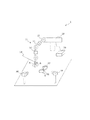
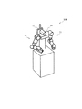
図1は、本発明の一実施形態におけるロボットシステム1の構成の一例を示すシステム構成図である。本実施形態におけるロボットシステム1は、主として、ロボット10と、ロボット制御部20と、第1撮像部30と、第2撮像部40とを備える。
<First Embodiment>
FIG. 1 is a system configuration diagram showing an example of a configuration of a robot system 1 according to an embodiment of the present invention. The robot system 1 in this embodiment mainly includes a
ロボット10は、複数のジョイント(関節)12と、複数のリンク13とを含むアーム11(可動部に相当)を有するアーム型のロボットである。アーム11の先端には、対象物(ワーク)を把持したり、道具を把持して対象物に対して所定の作業を行ったりすることが可能なハンド14(いわゆるエンドエフェクター又は手先効果器)が設けられる。
The
ジョイント12及びハンド14には、それらを動作させるためのアクチュエーター(図示せず)が設けられる。アクチュエーターは、例えば、サーボモーターやエンコーダーなどを備える。エンコーダーが出力するエンコーダー値は、ロボット制御部20によるロボット10のフィードバック制御に使用される。
The joint 12 and the
また、ハンド14の内部又はアーム11の先端等には、力覚センサー(図示せず)が設けられる。力覚センサーは、ハンド14に加わる力を検出する。力覚センサーとしては、例えば、並進3軸方向の力成分と、回転3軸回りのモーメント成分の6成分を同時に検出することができる6軸力覚センサーを用いることができる。また、力覚センサーで使用される物理量は、電流、電圧、電荷量、インダクタンス、ひずみ、抵抗、電磁誘導、磁気、空気圧、光等である。力覚センサーは、所望の物理量を電気信号に変換することにより、6成分を検出可能である。なお、力覚センサーは、6軸に限らず、例えば3軸でもよい。また、力覚センサーを設ける位置は、ハンド14に加わる力を検出できるのであれば、特に限定されるものではない。
Further, a force sensor (not shown) is provided in the
なお、ロボット10の構成は、本実施形態の特徴を説明するにあたって主要構成を説明したのであって、上記の構成に限られない。一般的な把持ロボットが備える構成を排除するものではない。例えば、図1では6軸のアームが示されているが、軸数(ジョイント数)をさらに増加させてもよいし、減らしてもよい。リンクの数を増減させてもよい。また、アーム、ハンド、リンク、ジョイント等の各種部材の形状、大きさ、配置、構造等も適宜変更してよい。また、エンドエフェクターはハンド14に限られない。また、配置空間を作ることの出来るロボットであれば、どのような態様のロボット、例えば自走式のロボットにも適用することもできる。
Note that the configuration of the
ロボット制御部20は、ロボット10の全体を制御する処理を行う。ロボット制御部20は、ロボット10の本体とは離れた場所に設置してもよいし、ロボット10等に内蔵してもよい。ロボット制御部20がロボット10の本体と離れた場所に設置されている場合には、ロボット制御部20は、有線又は無線でロボット10と接続される。
The
第1撮像部30及び第2撮像部40は、ロボット10の作業領域付近をそれぞれ異なる角度から撮像して、画像データを生成するユニットである。第1撮像部30及び第2撮像部40は、例えば、カメラを含み、作業台、天井、壁などに設けられる。第1撮像部30及び第2撮像部40としては、可視光カメラ、赤外線カメラ等を採用することができる。第1撮像部30及び第2撮像部40は複数のレンズを有し、レンズの光軸に沿った所定の領域内の対象物の画像を取得する。
The
第1撮像部30及び第2撮像部40はロボット制御部20に接続され、第1撮像部30及び第2撮像部40により撮像された画像はロボット制御部20に入力される。なお、第1撮像部30及び第2撮像部40は、ロボット制御部20ではなくロボット10に接続されるようにしてもよいし、ロボット10に内蔵されるようにしてもよい。この場合には、第1撮像部30及び第2撮像部40により撮像された画像は、ロボット10を介してロボット制御部20に入力される。
The first
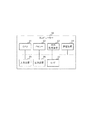
次に、ロボットシステム1の機能構成例について説明する。図2は、ロボット制御部20の機能ブロック図の一例である。
Next, a functional configuration example of the robot system 1 will be described. FIG. 2 is an example of a functional block diagram of the
ロボット10は、アクチュエーターのエンコーダー値、及びセンサーのセンサー値等に基づいてアーム11及びハンド14を制御する動作制御部101を備える。
The
動作制御部101は、ロボット制御部20から出力された情報、アクチュエーターのエンコーダー値、及びセンサーのセンサー値等に基づいてアーム11及びハンド14を制御する。例えば、動作制御部101は、ロボット制御部20から出力された移動方向及び移動量でアーム11を移動させるように、アクチュエーターを駆動させる。本実施の形態では、ハンド14がワークB(第2の物体に相当)を把持し、ワークBの表面にある軌道点B1(第2の位置に相当)が基準ワークA(第1の物体に相当)の表面にある目標位置A1(第3の位置に相当)に到達するように、動作制御部101がアーム11を駆動させる。
The
なお、本実施の形態では、基準ワークAが床等に載置されているため、基準ワークAを基準ワークとしている。しかしながら、基準ワークは制御の説明上、便宜的に定義したものである。基準ワークは、目標位置を定めることが可能な物体であればよく、特に限定されるものではない。また、この基準という表現は、ワークの形状、大きさ、位置等に関するものではない。 In the present embodiment, since the standard workpiece A is placed on the floor or the like, the standard workpiece A is used as the standard workpiece. However, the reference workpiece is defined for convenience in the explanation of the control. The reference workpiece may be any object that can determine the target position, and is not particularly limited. Further, the expression “reference” does not relate to the shape, size, position, etc. of the workpiece.
ロボット制御部20は、主として、画像取得部200と、画像処理部201と、目標位置算出部203と、制御部205と、サーボシステム206とを備える。また、画像処理部201は、基準ワーク認識部202と、ワーク認識部204とを有する。
The
画像取得部200は、第1撮像部30が撮像した画像(以下、第1画像という)及び第2撮像部40が撮像した画像(以下、第2画像という)を取得する。画像取得部200が取得した第1画像及び第2画像は、画像処理部201に出力される。
The
画像処理部201は、画像取得部200から出力された第1画像及び第2画像から、基準ワークA及びワークBを認識し、かつ目標位置A1及び軌道点B1を認識する。
The
ここで、第1画像及び第2画像から基準ワークA及びワークB(目標位置A1及び軌道点B1)が認識できる場合とは、第1撮像部30及び第2撮像部40のレンズと基準ワークA及びワークB(目標位置A1及び軌道点B1)とを結ぶ線上に他の物体(基準ワークA、ワークB、アーム11等)が含まれない場合である。この場合には、レンズから見て基準ワークA及びワークB(目標位置A1及び軌道点B1)が他の物体と重なっておらず、第1画像及び第2画像に基準ワークA及びワークB(目標位置A1及び軌道点B1)が含まれている。
Here, when the reference workpiece A and the workpiece B (target position A1 and trajectory point B1) can be recognized from the first image and the second image, the lenses and the reference workpiece A of the
第1画像及び第2画像から基準ワークA及びワークB(目標位置A1及び軌道点B1)が認識できない場合とは、第1撮像部30及び第2撮像部40のレンズと基準ワークA及びワークB(目標位置A1及び軌道点B1)とを結ぶ線上に他の物体が含まれる場合、すなわち基準ワークA及びワークB(目標位置A1及び軌道点B1)よりレンズ側に他の物体がある場合である。具体的には、基準ワークAよりレンズ側にアーム11、ハンド14、ワークBのいずれかがある場合や、ワークBよりレンズ側にアーム11、ハンド14、基準ワークAのいずれかがある場合である。この場合には、レンズから見て基準ワークA及びワークB(目標位置A1及び軌道点B1)が他の物体と重なっている。したがって、第1画像及び第2画像においては、基準ワークA及びワークB(目標位置A1及び軌道点B1)が他の物体により覆われており、視認できない。
When the reference workpiece A and workpiece B (target position A1 and trajectory point B1) cannot be recognized from the first image and the second image, the lenses of the
なお、ここでいう「レンズ」とは、最も撮影対象物に近いレンズ(一般的には対物レンズ)を想定しているが、撮像部を構成する全てのレンズが対象に含まれる。なお、第1撮像部30及び第2撮像部40が屈曲光学系を採用している場合には、光軸を折り曲げる光学要素より対物レンズ側(撮像素子から遠い側)のレンズが対象に含まれる。また、対物レンズの前面にカバーガラスが設けられている場合には、カバーガラスも対象に含まれる。
Note that the “lens” here is assumed to be a lens closest to the object to be photographed (generally an objective lens), but all lenses constituting the imaging unit are included in the object. In addition, when the
また、ここでいう、レンズから見て基準ワークA及びワークB(目標位置A1及び軌道点B1)が他の物体と重なっている場合とは、全部が重なる場合と一部が重なる場合が含まれる。また、全部が重なる場合には、ぴったり重なる場合と、背後に隠れてしまう場合が含まれる。 In addition, the case where the reference workpiece A and the workpiece B (target position A1 and trajectory point B1) overlap with other objects as viewed from the lens includes the case where all overlap and the case where a portion overlaps. . Moreover, when all overlap, the case where it overlaps exactly and the case where it hides behind are included.
基準ワーク認識部202は、画像取得部200から出力された第1画像及び第2画像から、基準ワークA及び目標位置A1が算出可能な画像情報を認識する。
The reference
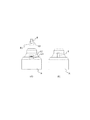
図3は、第1画像の例であり、(A)は目標位置A1が算出可能な画像情報が検出できる場合、(B)は目標位置A1が算出可能な画像情報が検出できない場合を示す。 3A and 3B show examples of the first image. FIG. 3A shows a case where image information that can calculate the target position A1 can be detected, and FIG. 3B shows a case that image information that can calculate the target position A1 cannot be detected.
本実施の形態では、図1に示すように、目標位置A1は穴の底であり、画像で直接視認することはできない。しかしながら、穴の深さが分かっている(例えば、メモリー22(後に説明)等に記憶されている)ため、穴の開口部A2(第1の位置に相当)の位置が分かれば目標位置A1は算出可能である。したがって、基準ワーク認識部202は、開口部A2を含む画像A3(図3(A)参照)を目標位置A1が算出可能な画像情報として第1画像及び第2画像から検出する。そして、基準ワーク認識部202は、画像A3から開口部A2を認識する。
In the present embodiment, as shown in FIG. 1, the target position A1 is the bottom of the hole and cannot be visually recognized directly in the image. However, since the depth of the hole is known (for example, stored in the memory 22 (described later) or the like), if the position of the hole opening A2 (corresponding to the first position) is known, the target position A1 is It can be calculated. Therefore, the reference
図3(A)に示すように、開口部A2が視認できる場合には、画像A3を検出することができる。それに対し、図3(B)に示すように、開口部A2が他の部材(ここでは、ワークB)により覆われており開口部A2が視認できない場合には画像A3が検出できない。したがって、画像A3は、開口部A2を含む最少範囲の画像とすることが望ましい。 As shown in FIG. 3A, when the opening A2 is visible, the image A3 can be detected. On the other hand, as shown in FIG. 3B, when the opening A2 is covered with another member (here, work B) and the opening A2 cannot be visually recognized, the image A3 cannot be detected. Therefore, it is desirable that the image A3 is a minimum range image including the opening A2.
なお、基準ワーク認識部202が行う画像認識処理は、特に限定されるものではなく、すでに公知の様々な技術を用いることができるため、説明を省略する。
Note that the image recognition processing performed by the reference
基準ワーク認識部202は、第1画像及び第2画像から開口部A2が認識された場合には、開口部A2の位置を示す情報を目標位置算出部203に出力する。また、基準ワーク認識部202は、第1画像又は第2画像から開口部A2が認識されなかった場合には、目標位置算出部203には何も出力されない。
When the opening A2 is recognized from the first image and the second image, the reference
目標位置算出部203は、目標位置A1が算出可能である場合には、画像A3から開口部A2を検出する。また、目標位置算出部203は、検出した開口部A2の位置と、穴の深さの情報とに基づいて、目標位置A1がどこであるかを示す情報(以下、目標位置A1の位置情報という)を算出する。算出された目標位置A1の位置情報は、制御部205に出力される。
The target
本実施の形態では、穴の断面は円形であるため、目標位置算出部203は、開口部A2の中心位置から穴の深さだけ基準ワークAの内側へ向かう方向へ移動(図1、3に示す場合は下方向へ移動)させた位置を、目標位置A1の位置と算出する。
In the present embodiment, since the hole has a circular cross section, the target
なお、本実施の形態では、円形の穴の開口部A2と穴の深さとから目標位置A1を算出したが、目標位置は穴の底とは限らず、様々な形態が考えられる。ただし、いかなる形態においても、目標位置は視認できない。したがって、本発明では、ワークの表面に露出した指標となる位置と、あらかじめ分かっている指標と目標位置との距離(所定の距離に相当)とから、目標位置を算出する。また、開口部A2の形状もこれに限らず、様々な形態が考えられる。ただし、開口部A2は、基準ワークAの表面の任意の位置であることは変わらない。また、目標位置A1は、基準ワークAの表面の任意の位置から、基準ワークAの表面の任意の位置と目標位置との距離だけ基準ワークAの内側へ離れた位置であることは変わりない。 In the present embodiment, the target position A1 is calculated from the opening A2 of the circular hole and the depth of the hole. However, the target position is not limited to the bottom of the hole, and various forms are conceivable. However, the target position cannot be visually recognized in any form. Therefore, in the present invention, the target position is calculated from the position serving as the index exposed on the surface of the workpiece and the distance between the previously known index and the target position (corresponding to a predetermined distance). Further, the shape of the opening A2 is not limited to this, and various forms are conceivable. However, the opening A2 remains the same at any position on the surface of the reference workpiece A. Further, the target position A1 is not changed from an arbitrary position on the surface of the reference workpiece A to a position inside the reference workpiece A by a distance between an arbitrary position on the surface of the reference workpiece A and the target position.
ワーク認識部204は、画像取得部200から出力された第1画像及び第2画像から、ワークB及び軌道点B1を検出する。本実施の形態では、軌道点B1は、ワークBの先端である。したがって、ワーク認識部204は、図3(A)に示すように、ワークB先端(軌道点B1)を含む画像B2を第1画像及び第2画像から検出する。そして、ワーク認識部204は、画像B2から軌道点B1を認識する。
The
本実施の形態では、ワークBは円柱形である。したがって、ワーク認識部204は、先端の径方向の中心位置を軌道点B1とする。なお、ワークBの断面形状は円形に限らず、基準ワークAの開口部A2と同じ形状であれば、どのような形状でもよい。また、ワークBの形状に応じて、軌道点B1の位置も様々な位置となり得る。ただし、軌道点B1は、ワークBの表面の任意の位置であることは変わらない。
In the present embodiment, the workpiece B has a cylindrical shape. Therefore, the
図3(A)に示すように、軌道点B1が視認できる場合には、画像B2を検出することができる。それに対し、図3(B)に示すように、軌道点B1が他の部材(ここでは、基準ワークA)により覆われており軌道点B1が視認できない場合には画像B2が検出できない。なお、画像B2は、軌道点B1を含む最少範囲の画像とすることが望ましい。 As shown in FIG. 3A, when the trajectory point B1 is visible, the image B2 can be detected. On the other hand, as shown in FIG. 3B, when the trajectory point B1 is covered with another member (here, the reference workpiece A) and the trajectory point B1 cannot be visually recognized, the image B2 cannot be detected. Note that the image B2 is desirably a minimum range image including the trajectory point B1.
ワーク認識部204は、第1画像及び第2画像から画像B2が認識できた場合には、画像B2から軌道点B1を検出する。そして、ワーク認識部204は、軌道点B1の位置を示す情報を制御部205に出力する。ワーク認識部204は、第1画像又は第2画像から画像B2が認識できなかった場合には、制御部205に何も出力しない。
When the
なお、ワーク認識部204が行う画像認識処理は、特に限定されるものではなく、すでに公知の様々な技術を用いることができるため、説明を省略する。
Note that the image recognition processing performed by the
制御部205は、基準ワーク認識部202、目標位置算出部203、ワーク認識部204から出力された情報に基づいて、開口部A2及び軌道点B1が認識できた場合と、そうでない場合とで、異なる制御方法を用いてアーム11及びハンド14等を制御する。具体的には、制御部205は、基準ワーク認識部202、ワーク認識部204からの出力に基づいて、開口部A2及び軌道点B1が認識できたか否かを判断する。また、制御部205は、判断結果に基づいて、ビジュアルサーボを用いるか、インピーダンス制御を用いるかの切り替えを行う。そして、制御部205は、目標位置算出部203から出力された目標位置に、軌道点B1を近づけるようにハンド14が把持するワークBを移動させ、目標位置に軌道点B1を一致させるようにする。
Based on the information output from the reference
なお、ビジュアルサーボは、目標物との相対的な位置の変化を視覚情報として計測し、それをフィードバック情報として用いることによって目標物を追跡する制御手法である。本実施の形態では、ステレオ視などの方法を用いて計算した対象の3次元位置情報に基づいてロボットを制御する位置ベース法を採用する。 The visual servo is a control method for tracking a target by measuring a change in position relative to the target as visual information and using it as feedback information. In this embodiment, a position-based method for controlling the robot based on the three-dimensional position information of the target calculated using a method such as stereo vision is adopted.
また、インピーダンス制御は、ロボットの手先(ハンド14)に外から力を加えた場合に生じる機械的なインピーダンス(慣性、減衰係数、剛性)を、目的とする作業に都合の良い値に設定するための位置と力の制御手法である。例えば、減衰係数を低く設定した場合、軽い力でロボットが動作するため移動が容易である反面、安定性が低く、位置決めなど精密な動作には不適な特性となる。ここで、安定性が低いとは、移動後に目標位置での停止が難しい、ロボットが他の物体に強い力(破壊する可能性がある力)で接触してしまう等を意味する。一方、減衰係数を高く設定した場合、抵抗が大きくなり移動が困難になる反面、安定性が高くなり、位置決めなど精密な動作に適した特性となる。ここで、安定性が高いとは、移動後に目標位置での停止が容易、ロボットが他の物体に接触する場合においても適切な接触強度で接触する等を意味する。 In impedance control, mechanical impedance (inertia, damping coefficient, rigidity) generated when force is applied to the hand of the robot (hand 14) from the outside is set to a value convenient for the intended work. This is a method for controlling the position and force of the robot. For example, when the attenuation coefficient is set low, the robot moves easily with a light force, but is easy to move. However, the stability is low, and the characteristics are not suitable for precise operations such as positioning. Here, low stability means that it is difficult to stop at the target position after movement, or that the robot comes into contact with another object with a strong force (a force that may cause destruction). On the other hand, when the damping coefficient is set high, the resistance increases and the movement becomes difficult, but the stability increases and the characteristics are suitable for precise operations such as positioning. Here, high stability means that it is easy to stop at the target position after movement, and that the robot comes into contact with an appropriate contact strength even when it comes into contact with another object.
インピーダンス制御を用いる場合には、機械的なインピーダンス(柔らかさ)を適切な目標値に設定する事によって、外力と同じ方向に、マニピュレーターが受ける外力に応じた適切な柔らかさ(移動速度、安定性等)で作業を行なわることができる。これにより、ワークやロボット自体を破壊することを防止する、もしくはワークやロボット自体を破壊する可能性を低減することができる。本実施の形態では、手先の位置、速度、力などの測定値を用いたフィードバック制御でインピーダンスを変更する能動インピーダンス法を採用する。 When using impedance control, by setting the mechanical impedance (softness) to an appropriate target value, in the same direction as the external force, the appropriate softness (movement speed, stability) according to the external force received by the manipulator Etc.). Thereby, it is possible to prevent the workpiece and the robot itself from being destroyed, or to reduce the possibility of destroying the workpiece and the robot itself. In the present embodiment, an active impedance method is employed in which the impedance is changed by feedback control using measured values such as the position, speed, and force of the hand.
なお、ビジュアルサーボ、インピーダンス制御は、すでに公知の制御手法であるため、詳細な説明を省略する。 Note that visual servo and impedance control are already known control methods, and thus detailed description thereof is omitted.
制御部205は、ビジュアルサーボの場合には、仮想変位V(第1の量に相当)だけ軌道点B1を移動させるように、軌道点B1の移動量及び移動方向を算出する。また、制御部205は、インピーダンス制御の場合には、仮想変位I(第2の量に相当)だけ軌道点B1を移動させるように、軌道点B1の移動量及び移動方向を算出する。仮想変位V、Iとは、軌道点B1、すなわちハンド14の変位である。なお、仮想変位Iは、仮想変位Vより小さく設定されている。制御部205が行う処理の詳細については、後に詳述する。
In the case of visual servo, the
サーボシステム206は、制御部205から出力された情報に基づいてアーム11を制御するように、動作制御部101に情報を出力する。これにより、ハンド14の位置及び向き等が変更可能となる。
The
また、サーボシステム206は、制御部205がインピーダンス制御を用いる場合には、動作制御部101によるアーム11の制御による軌道点B1、すなわちハンド14の各方向成分の移動量を制御部205へ出力する。さらに、サーボシステム206は、作業が終了していない場合には、第1画像及び第2画像を撮像するように、第1撮像部30及び第2撮像部40に指示を出力する。サーボシステム206が行う処理の詳細については、後に詳述する。
In addition, when the
図4は、ロボット制御部20の概略構成の一例を示すブロック図である。図示するように、例えばコンピューターなどで構成されるロボット制御部20は、演算装置であるCPU(Central Processing Unit)21と、揮発性の記憶装置であるRAM(Random Access Memory)や不揮発性の記憶装置であるROM(Read only Memory)からなるメモリー22と、外部記憶装置23と、ロボット10等の外部の装置と通信を行う通信装置24と、マウスやキーボード等の入力装置25と、ディスプレイ等の出力装置26と、ロボット制御部20と他のユニットを接続するインターフェイス(I/F)27とを備える。
FIG. 4 is a block diagram illustrating an example of a schematic configuration of the
上記の各機能部は、例えば、CPU21がメモリー22等に格納された所定のプログラムをメモリー22等に読み出して実行することにより実現される。なお、所定のプログラムは、例えば、予めメモリー22等にインストールされてもよいし、通信装置24を介してネットワークからダウンロードされてインストール又は更新されてもよい。
Each functional unit described above is realized, for example, when the
以上のロボットシステム1の構成は、本実施形態の特徴を説明するにあたって主要構成を説明したのであって、上記の構成に限られない。例えば、ロボット10がロボット制御部20や第1撮像部30及び第2撮像部40を備えていてもよい。また、一般的なロボットシステムが備える構成を排除するものではない。
The configuration of the robot system 1 described above is not limited to the above-described configuration because the main configuration has been described in describing the features of the present embodiment. For example, the
次に、本実施形態における、上記構成からなるロボットシステム1の特徴的な処理について説明する。 Next, a characteristic process of the robot system 1 having the above configuration in the present embodiment will be described.
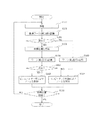
図5は、本発明のアーム11及びハンド14の制御処理の流れを示すフローチャートである。この処理は、任意のタイミングで、例えば、図示しないボタン等を介してビジュアルサーボの開始指示が入力されることにより開始される。本実施の形態では、ロボット10がワークBであるピンを、基準ワークAの穴に圧入する圧入作業を例に説明する。
FIG. 5 is a flowchart showing a flow of control processing of the
画像取得部200は、第1撮像部30及び第2撮像部40から第1画像及び第2画像を取得する(ステップS100)。取得された画像データは、基準ワーク認識部202及びワーク認識部204に出力される。
The
基準ワーク認識部202は、第1画像及び第2画像から基準ワークAの開口部A2を認識する(ステップS102)。そして、基準ワーク認識部202は、開口部A2が認識できたか否かを判断する(ステップS104)。
The reference
開口部A2が認識できたと判断された場合(ステップS104でYES)には、基準ワーク認識部202は、開口部A2の位置を示す情報を目標位置算出部203に出力する。目標位置算出部203は、取得した情報に基づいて目標位置A1の位置情報を更新する(ステップS106)。
If it is determined that the opening A2 can be recognized (YES in step S104), the reference
ワーク認識部204は、第1画像及び第2画像からワークBの軌道点B1を認識する(ステップS108)。そして、ワーク認識部204は、軌道点B1が認識できたか否かを判断する(ステップS110)。
The
軌道点B1が認識できた場合(ステップS110でYES)には、ワーク認識部204は、軌道点B1の位置を示す情報を制御部205に出力する。また、制御部205は、ビジュアルサーボによりアーム11を制御する(ステップS112)。以下、ビジュアルサーボによりアーム11を制御する方法を、詳細に説明する。
When the trajectory point B1 can be recognized (YES in step S110), the
制御部205は、ワーク認識部204から出力された情報に基づいて、軌道点B1の位置がどこであるかを示す情報(以下、軌道点B1の位置情報という)を算出する。そして、制御部205は、算出された軌道点B1の位置情報と、目標位置算出部203から取得した目標位置A1の位置情報とに基づいて、軌道点B1の仮想変位Vと移動方向とを算出する。制御部205は、ビジュアルサーボにより軌道点B1、すなわちハンド14を仮想変位Vだけ算出された移動方向へ移動させることを示す情報を、サーボシステム206に出力する。
Based on the information output from the
サーボシステム206は、制御部205から出力された情報に基づいて、軌道点B1、すなわちハンド14の移動方向及び移動量を求める。具体的には、仮想変位Vを各方向(x方向、y方向、z方向)成分に分解することにより、x方向の移動量、y方向の移動量、z方向の移動量を算出する。そして、サーボシステム206は、ビジュアルサーボにより、算出された移動量だけハンド14をx方向、y方向、z方向に移動させるように、動作制御部101へ指示を出力する。
The
動作制御部101は、サーボシステム206から出力された指示に基づいて、アーム11を移動させる。これにより、ビジュアルサーボによりアーム11を制御するステップ(ステップS112)が終了する。
The
軌道点B1が認識できなかった場合(ステップS110でNO)には、制御部205は、インピーダンス制御によりアーム11を制御する(ステップS114)。以下、インピーダンス制御によりアーム11を制御する方法を、詳細に説明する。
When the trajectory point B1 cannot be recognized (NO in step S110), the
制御部205は、ワーク認識部204及びサーボシステム206から出力された情報に基づいて、軌道点B1の位置情報を算出する。具体的には、制御部205は、ワーク認識部204から最後に取得した情報、すなわち最後に認識された軌道点B1の位置に、サーボシステム206から出力されたハンド14の各方向成分の移動量を加算して、現在の軌道点B1の位置情報を算出する。そして、制御部205は、算出された軌道点B1の位置情報と、目標位置算出部203から取得した目標位置A1の位置情報とに基づいて、軌道点B1、すなわちハンド14の仮想変位Iと移動方向とを算出する。
The
インピーダンス制御は、画像から軌道点B1(又は開口部A2)が検出できない場合に行うものである。したがって、基準ワークAとワークBとがぶつかっている可能性もある。したがって、より安全に作業を行うため、インピーダンス制御の時の仮想変位Iは、仮想変位Vより小さく設定している。 The impedance control is performed when the trajectory point B1 (or the opening A2) cannot be detected from the image. Therefore, there is a possibility that the reference workpiece A and the workpiece B are colliding. Therefore, the virtual displacement I at the time of impedance control is set smaller than the virtual displacement V in order to perform work more safely.
制御部205は、インピーダンス制御によりハンド14を仮想変位Iだけ算出された移動方向へ移動させることを示す情報を、サーボシステム206に出力する。
The
サーボシステム206は、制御部205から取得した情報に基づいてハンド14の移動方向及び移動量を求める。具体的には、サーボシステム206は、仮想変位Iを各方向(x方向、y方向、z方向)成分に分解することにより、x方向の移動量、y方向の移動量、z方向の移動量を算出する。そして、サーボシステム206は、インピーダンス制御により、算出された移動量だけハンド14をx方向、y方向、z方向に移動させるように、動作制御部101へ指示を出力する。
The
動作制御部101は、サーボシステム206から出力された指示に基づいて、アーム11を移動させる。これにより、インピーダンス制御によりアーム11を制御するステップ(ステップS114)が終了する。
The
本実施の形態では、軸の圧入作業であるため、ワークBに外力がかかる可能性が高い。しかしながら、インピーダンス制御を行うことにより、外力がかかる場合においても、確実にワークBを仮想変位Iだけ移動させることができる。 In this embodiment, since the shaft is press-fitted, there is a high possibility that an external force is applied to the workpiece B. However, by performing impedance control, the workpiece B can be reliably moved by the virtual displacement I even when an external force is applied.
開口部A2が認識できなかった場合(ステップS104でNO)には、基準ワーク認識部202から目標位置算出部203へ情報が入力されないため、目標位置算出部203は、目標位置A1が算出不可能であることと判断し、直前に算出された目標位置A1の位置情報を制御部205へ出力する。その後、ステップS109へ進む。
If the opening A2 cannot be recognized (NO in step S104), no information is input from the reference
ワーク認識部204は、第1画像及び第2画像からワークBの軌道点B1を認識する(ステップS109)。当該処理は、ステップS108の処理と同じである。軌道点B1が認識できた場合は、ワーク認識部204は、軌道点B1の位置を示す情報を制御部205に出力する。制御部205は、インピーダンス制御により可動部を制御する(ステップS114)。この場合は、目標位置A1の位置情報が画像から分からないため、軌道点B1が認識できたか否かにかかわらず、インピーダンス制御を行う。ステップS114の処理については、すでに説明したため、ここでは説明を省略する。
The
このように、本実施の形態では、開口部A2、軌道点B1のどちらかが画像から検出されなかった場合には、インピーダンス制御を行う。開口部A2、軌道点B1の両方が画像から検出されなかった場合にも、インピーダンス制御を行う。インピーダンス制御は、インピーダンスが設定されているため、基準ワークAとワークBとがぶつかったとしても、ワークBが設定された方向に無理やり動かれることがないため、基準ワークAやワークBが破壊されずに済み、安全に作業を継続することができる。 Thus, in the present embodiment, impedance control is performed when either the opening A2 or the trajectory point B1 is not detected from the image. Impedance control is also performed when both the opening A2 and the trajectory point B1 are not detected from the image. In the impedance control, since the impedance is set, even if the reference workpiece A and the workpiece B collide, the workpiece B cannot be forcibly moved in the set direction, so that the reference workpiece A and the workpiece B are destroyed. So you can continue working safely.
ビジュアルサーボ又はインピーダンス制御により軌道点B1、すなわちハンド14が仮想変位V、Iだけ移動された(ステップS112、S114)ら、サーボシステム206は、移動後の軌道点B1の位置情報と、目標位置A1の位置情報とが一致する、すなわち軌道点B1が目標位置A1に到達したか否かを判断する(ステップS116)。
After the trajectory point B1, that is, the
軌道点B1が目標位置A1に到達していない場合(ステップS116でNO)は、サーボシステム206は、指示を第1撮像部30及び第2撮像部40に出力する。すると、第1撮像部30及び第2撮像部40は第1画像及び第2画像を撮像し、画像取得部200は第1画像及び第2画像を取得する(ステップS100)。これにより、ステップS100〜S116が繰り返し行われる。軌道点B1が目標位置A1に到達している場合(ステップS116でYES)は、処理を終了する。
When the trajectory point B1 has not reached the target position A1 (NO in step S116), the
このように図5に記載のフローを繰り返し行うことにより、画像から目標位置A1や軌道点B1が見える状態から見えない状態となった場合には、ビジュアルサーボからインピーダンス制御へと切り替えられる。また、画像から目標位置A1や軌道点B1が見えない状態から見える状態へ戻った場合には、インピーダンス制御からビジュアルサーボへと切り替えられる。 As described above, when the flow shown in FIG. 5 is repeatedly performed and the target position A1 and the trajectory point B1 are not visible from the image, the visual servo is switched to the impedance control. Further, when the target position A1 or the trajectory point B1 is returned from a state where the target position A1 or the trajectory point B1 is not visible, the impedance control is switched to the visual servo.
本実施の形態によれば、ワーク等が画像から認識できない場合にはインピーダンス制御を行うため、ワーク等が画像から認識できない場合にも、安全に作業を継続することができる。 According to the present embodiment, impedance control is performed when a workpiece or the like cannot be recognized from the image, and therefore the work can be safely continued even when the workpiece or the like cannot be recognized from the image.
また、本実施の形態によれば、軌道点や目標位置が画像から認識できる場合には、ビジュアルサーボを用いるため、作業の都度、基準ワークAの位置が異なっていても、作業を行うことができる。したがって、毎回同じ位置に基準ワークAを設置する必要がなく、作業効率を高くすることができる。 Further, according to the present embodiment, when the trajectory point and the target position can be recognized from the image, the visual servo is used, so that the work can be performed even if the position of the reference work A is different every time the work is performed. it can. Therefore, it is not necessary to install the reference workpiece A at the same position every time, and work efficiency can be increased.
さらに、本実施の形態によれば、どのような制御方法を用いた場合においても、ワークの内部にあって視認できない目標位置へ、ハンドが把持するワークを移動させることができる。 Furthermore, according to the present embodiment, regardless of what control method is used, the work gripped by the hand can be moved to a target position inside the work that cannot be visually recognized.
なお、本実施形態では、ビジュアルサーボとインピーダンス制御とを切り替える例として、軸の圧入作業を用いて説明したが、ビジュアルサーボとインピーダンス制御とを切り替えることが有効な場合はこれに限られない。例えば、コネクタを挿す作業、蓋をはめる作業等の複数の部品を組み合わせる作業であれば、様々な作業に適用できる。また、本実施の形態では、エンドエフェクターとしてハンドを用い、ハンドでワークを把持したが、エンドエフェクターはワークの種類によって様々な形態が考えられる。また、ハンドはワークを把持したが、エンドエフェクターの種類によっては様々な形でワークを保持することができる。 In the present embodiment, as an example of switching between visual servo and impedance control, the shaft press-fitting operation has been described. However, the case where switching between visual servo and impedance control is effective is not limited thereto. For example, any work that combines a plurality of parts, such as a work for inserting a connector and a work for attaching a lid, can be applied to various work. Further, in this embodiment, a hand is used as an end effector, and a work is gripped by the hand, but various forms of the end effector can be considered depending on the type of work. Moreover, although the hand has gripped the workpiece, the workpiece can be held in various forms depending on the type of the end effector.
また、本実施形態では、開口部A2が視認できない場合として開口部A2がワークBにより覆われた場合を示し、軌道点B1が視認できない場合として軌道点B1が基準ワークAにより覆われた場合を示した(図3(B)参照)が、開口部A2、軌道点B1が視認できない場合はこれに限られない。開口部A2、軌道点B1が視認できない場合としては、開口部A2や軌道点B1が他の部品、例えばアーム11等により物理的に覆われている場合も考えられる。また、開口部A2、軌道点B1が視認できない場合としては、開口部A2、軌道点B1が物理的に覆われていなくても、金属光沢の反射等により開口部A2、軌道点B1が画像認識処理により認識できない場合も考えられる。さらに開口部A2、軌道点B1が視認できない場合としては、開口部A2、軌道点B1が第1画像、第2画像の想定している範囲(例えば、中央部分の所定範囲)にない時や、開口部A2、軌道点B1が第1画像、第2画像に含まれていない場合も考えられる。以上の場合と異なり、開口部A2、軌道点B1が認識できた場合であっても、開口部A2、軌道点B1との位置関係が想定している位置関係にない(例えば、ワークBは基準ワークAより上にある)場合を、開口部A2、軌道点B1が視認できない場合に含めてもよい。
Moreover, in this embodiment, the case where opening A2 is covered with the workpiece | work B is shown as a case where opening A2 cannot be visually recognized, and the case where track point B1 is covered with the reference | standard workpiece A as a case where track point B1 cannot be visually recognized. Although shown (refer FIG. 3 (B)), when the opening part A2 and the track point B1 cannot be visually recognized, it is not restricted to this. As a case where the opening A2 and the trajectory point B1 cannot be visually recognized, there may be a case where the opening A2 and the trajectory point B1 are physically covered by other parts such as the
なお、本実施の形態では、サーボシステム206から第1撮像部30及び第2撮像部40に撮像指示を出力したが、これに限られるわけではなく、例えば、撮像指示を画像取得部200に出力し、画像取得部200から第1撮像部30及び第2撮像部40に指示を出力してもよい。
In the present embodiment, the imaging instruction is output from the
なお、本実施の形態では、力、値、位置の情報、撮像結果、認識結果、判断結果等の何らかの情報に基づいて処理(アーム11の制御、ハンド14の移動等)を行っているが、情報に基づいて処理を行うとは、情報そのものを使って処理を行うこと、情報を加工等して得られた結果を使って処理を行うこと、情報の一部を取り出して処理を行うこと等を含む。
In this embodiment, processing (control of the
例えば、撮像結果に基づいて処理を行う場合には、撮像して得られた画像を使って処理をしてもよいし、画像に対して任意の画像処理をして得られた結果を使って処理をしてもよいし、画像に含まれる輝度、色データ等を取り出して処理をしてもよいし、画像の一部領域のデータのみを取り出して処理をしてもよいし、画像のタグ等に含まれる情報を取り出して処理をしてもよい。また、画像に対して任意の画像処理をして得られた結果とは、例えば、位置情報(座標)、大きさの情報、形状の情報、位置関係を示す情報、物体の有無を示す情報等が含まれる。 For example, when processing is performed based on the imaging result, the processing may be performed using an image obtained by imaging, or the result obtained by performing arbitrary image processing on the image may be used. Processing may be performed, luminance and color data included in the image may be extracted and processed, or only a partial area of the image may be extracted and processed. Or the like. The results obtained by performing arbitrary image processing on the image include, for example, position information (coordinates), size information, shape information, positional relationship information, information indicating the presence or absence of an object, etc. Is included.
また、例えば、力に基づいて処理を行う場合には、センサー等の出力値やアクチュエータ等での測定値等(以下、測定値という)をそのまま使って処理をしてもよいし、測定値を用いて算出された値を使って処理をしてもよいし、測定値と測定値を用いて算出された値との合成結果を使って処理をしてもよいし、測定値の合計値を使って処理をしてもよい。 In addition, for example, when processing is performed based on force, processing may be performed using output values from sensors, measurement values from actuators, etc. (hereinafter referred to as measurement values) as they are, May be processed using the calculated value, or may be processed using the result of combining the measured value and the value calculated using the measured value. You may use it for processing.
<第2の実施形態>
本発明の第1の実施形態は、片腕ロボットを用いて、床、台等の平面に置いてある基準ワークAにワークBを圧入したが、本発明の適用範囲はこれに限定されない。
<Second Embodiment>
In the first embodiment of the present invention, the workpiece B is press-fitted into the reference workpiece A placed on a plane such as a floor or a stand using a one-arm robot, but the scope of application of the present invention is not limited to this.
本発明の第2の実施形態は、双腕ロボットに本発明を適用した形態である。以下、本発明の第2の実施形態について説明する。なお、処理の流れは第1の実施形態と同一であるため、構成についてのみ説明する。また、第1の実施形態と同一の部分については、同一の符号を付し、説明を省略する。 The second embodiment of the present invention is a form in which the present invention is applied to a double-arm robot. Hereinafter, a second embodiment of the present invention will be described. Since the processing flow is the same as that of the first embodiment, only the configuration will be described. Further, the same portions as those in the first embodiment are denoted by the same reference numerals, and description thereof is omitted.
図6は、本発明の一実施形態におけるロボットシステム2の構成の一例を示すシステム構成図である。本実施形態におけるロボットシステム2は、主として、ロボット10Aと、ロボット制御部20と、第1撮像部30と、第2撮像部40とを備える。
FIG. 6 is a system configuration diagram showing an example of the configuration of the robot system 2 in one embodiment of the present invention. The robot system 2 in the present embodiment mainly includes a
ロボット10Aは、複数のジョイント(関節)12と、複数のリンク13とを含むアーム11を複数(本実施の形態では2本)有するアーム型のロボット、いわゆる双腕ロボットである。2本のアーム11の先端には、それぞれ、ハンド14(いわゆるエンドエフェクター)が設けられる。
The
2個のハンド14のうちの一本がワークBを把持し、他の一本が基準ワークAを把持する。2個のハンド14のうちのどちらのハンド14が、どちらのワーク(基準ワークA又はワークB)を把持するかは、任意である。第1の実施の形態と同様、ワークBが挿入される側の大きいワークを、便宜上基準ワークAとしているが、ワークBを基準ワークとしてもよい。また、この基準という表現は、ワークの形状、大きさ、位置等に関するものではない。
One of the two
このように、本発明は、載置されたワークに他のワークを挿入等する場合に限らず、複数の可動部がそれぞれワークを把持し、把持されたワークどうしを組み合わせ等する場合にも適用できる。例えば、複数の歯車が適切に噛み合うように歯車を配置する場合、複数の物体を位置合わせして載置する場合にも適用できる。さらに、接着剤、ペースト状のはんだ等を吐出する装置をハンドで把持し、接着剤、ペースト状のはんだ等を任意の位置に吐出させる場合等にも適用できる。 As described above, the present invention is not limited to the case where other workpieces are inserted into the placed workpiece, but is also applied to a case where a plurality of movable parts each grip the workpiece and combine the gripped workpieces. it can. For example, the present invention can be applied to a case where gears are arranged so that a plurality of gears mesh appropriately and a plurality of objects are aligned and placed. Furthermore, the present invention can also be applied to a case where a device for discharging adhesive, paste-like solder, or the like is held by a hand and the adhesive, paste-like solder, or the like is discharged to an arbitrary position.
<その他変形例>
上記第1、第2の実施の形態では、ビジュアルサーボとインピーダンス制御とを切り替えたが、ビジュアルサーボと切り替えるのはインピーダンス制御に限られない。例えば、以下に示すような制御方法も考えられる。
<Other variations>
In the first and second embodiments, visual servo and impedance control are switched. However, switching to visual servo is not limited to impedance control. For example, the following control method is also conceivable.
上記第1、第2の実施形態で用いた軸の圧入や、摩擦および隙間のない丸棒の穴等への挿入作業を考える。挿入方向と平行な軸をz軸とし、z軸と垂直な面上にx軸、y軸を設定すると、上記作業においては、x、y軸方向及びx、y軸回りの運動と、z軸方向及びz軸回りの力の発生とが拘束される(自然拘束)。したがって、作業の達成には、x、y軸方向及びx、y回りの許容干渉力と、z軸方向の挿入速度およびz軸回りの許容回転速度(人工拘束)の設定が必要となる。したがって、圧入、挿入作業を行う場合には、拘束条件に基づき、エンドエフェクターの運動を干渉力に応じて修正するコンプライアンス(順応)機能を有するコンプライアンス制御を行うことにより、作業を効果的に実行することができる。 Consider the press-fitting of the shaft used in the first and second embodiments, and the insertion operation into a hole in a round bar without friction and clearance. When the axis parallel to the insertion direction is the z-axis and the x-axis and y-axis are set on a plane perpendicular to the z-axis, in the above operation, the movement around the x- and y-axes and the x- and y-axes and the z-axis Direction and generation of force around the z-axis are constrained (natural constraint). Therefore, in order to achieve the work, it is necessary to set the x, y axis direction and the allowable interference force around x, y, the insertion speed in the z axis direction, and the allowable rotation speed (artificial constraint) around the z axis. Therefore, when performing press-fitting and insertion work, the work is effectively executed by performing compliance control having a compliance (adaptation) function for correcting the movement of the end effector according to the interference force based on the constraint condition. be able to.
コンプライアンス制御では、エンドエフェクターに加えられた力に応じてエンドエフェクターが変位する。例えば、穴へピンを挿入する作業を行う場合には、挿入方向(エンドエフェクターを移動させる方向、穴の軸方向)には一定力で押しつけ、挿入方向以外の方向には外力を加えないというように、各方向別に押しつけ力を設定する。穴とピンが当接している場合には、挿入方向以外の方向に外力が加わるため、穴とピンとが当接しないように、エンドエフェクターが受けた力の方向にエンドエフェクターを変位させ、穴とピンとをなじませる。したがってコンプライアンス制御を用いることで、穴の軸とピンの軸とがずれている場合においても、ピンの穴への挿入が可能となる。これにより、ロボットやピン、穴等を破壊することを防止する、もしくはロボットやピン、穴等を破壊する可能性を低減することができる。 In the compliance control, the end effector is displaced according to the force applied to the end effector. For example, when performing the work of inserting a pin into a hole, it is pressed with a constant force in the insertion direction (the direction in which the end effector is moved, the axial direction of the hole), and no external force is applied in directions other than the insertion direction. Set the pressing force for each direction. When the hole and the pin are in contact, an external force is applied in a direction other than the insertion direction, so the end effector is displaced in the direction of the force received by the end effector so that the hole and the pin do not contact. Familiarize with the pins. Therefore, by using compliance control, even when the axis of the hole and the axis of the pin are deviated, the pin can be inserted into the hole. Thereby, it is possible to prevent the robot, the pin, the hole and the like from being destroyed, or to reduce the possibility of destroying the robot, the pin, the hole and the like.
また、アーム11及びハンド14等に組立て、研磨、ばり取り、クランク回しなどの作業をさせる際には、ハンド14等のエンドエフェクターの位置だけでなく、ロボットが対象物に印加する力をも制御することが必要となる。インピーダンス制御は、エンドエフェクターに作用する干渉力とエンドエフェクターの運動との間の関係(インピーダンス)を調節する方法であるため、このような作業に対しても効果的である。それに加え、位置を制御したい方向および力を制御したい方向を定め、それぞれの方向の位置や力が希望の値になるように複数の制御方式を適用するハイブリッド制御を用いた場合も、このような作業に対しても効果的である。
In addition, when assembling, polishing, deburring, cranking, etc. on the
すなわち、画像から基準ワークAやワークBが認識できなくなったときに、ハイブリッド制御、コンプライアンス制御等の干渉力を巧妙に制御することができる制御方法へビジュアルサーボから切り替えた場合にも、安全に作業を継続することができるという本発明の効果を達成できる。 In other words, when the reference workpiece A or workpiece B cannot be recognized from the image, even if the visual servo is switched to a control method capable of skillfully controlling the interference force such as hybrid control and compliance control, the work can be performed safely. Thus, the effect of the present invention can be achieved.
なお、ハイブリッド制御、コンプライアンス制御等の干渉力を巧妙に制御することができる制御方法を行うためには、ハンド14等のエンドエフェクターに加わる力を検出することが好ましい。エンドエフェクターに加わる力は、第1、第2の実施の形態のように、力覚センサー等で直接測定することもできるし、アーム11の各軸トルク値からエンドエフェクターに及ぼす外力を推定することもできる。したがって、干渉力を制御することができる制御方法は、直接または間接的にエンドエフェクターに加わる力を取得する手段を、アーム11等が有していれば実行可能である。
In order to perform a control method capable of skillfully controlling the interference force such as hybrid control and compliance control, it is preferable to detect the force applied to the end effector such as the
また、上記第1、第2の実施の形態では、ビジュアルサーボとインピーダンス制御とを切り替えたが、本発明の範囲はビジュアルサーボとインピーダンス制御とを切り替える場合に限られない。第1画像、第2画像から軌道点、目標位置が視認できる場合にはビジュアルサーボを行い、第1画像、第2画像から軌道点、目標位置が視認できない場合にはインピーダンス制御を行えばよい。例えば、第1画像、第2画像から軌道点、目標位置が視認できる場合にはビジュアルサーボとインピーダンス制御とを両方行う制御方式を行い、第1画像、第2画像から軌道点、目標位置が視認できなくなったらビジュアルサーボをやめてインピーダンス制御のみを行うようにしてもよい。ビジュアルサーボとインピーダンス制御とを両方行う制御方式を用いることで、可動部をより大きく動かすことができる。 In the first and second embodiments, visual servo and impedance control are switched. However, the scope of the present invention is not limited to switching between visual servo and impedance control. Visual servo is performed when the orbit point and the target position can be visually recognized from the first image and the second image, and impedance control may be performed when the orbit point and the target position cannot be visually recognized from the first image and the second image. For example, when the trajectory point and the target position can be visually recognized from the first image and the second image, a control method for performing both visual servo and impedance control is performed, and the trajectory point and the target position are visually recognized from the first image and the second image. If it becomes impossible, the visual servo may be stopped and only impedance control may be performed. By using a control method that performs both visual servoing and impedance control, the movable part can be moved more greatly.
また、上記第1、第2の実施の形態では、第1撮像部30及び第2撮像部40の2個の撮像部を備えたが、撮像部は1つでもよいし、3つ以上でもよい。例えば、撮像部が1つだけの場合には、撮像部から見て奥行き方向の位置を認識することは難しい。しかしながら、撮像部が1つだけの場合にも、仮想的な制約平面を設定することにより、奥行き方向の位置を決定することができる。また、撮像部が1つだけの場合、物理的な制約面を設定してインピーダンス制御、コンプライアンス制御等を行うようにしてもよい。
In the first and second embodiments, two imaging units, the
なお、第1、第2の実施の形態では、第1撮像部30及び第2撮像部40を備えているため、第1画像、第2画像のどちらかから開口部A2、軌道点B1が視認できない場合には、開口部A2、軌道点B1が視認できない場合としたが、第1画像、第2画像の両方から開口部A2、軌道点B1が視認できない場合にのみ、開口部A2、軌道点B1が視認できない場合としてもよい。ただし、作業の安全性を高めるためには、第1画像、第2画像のどちらかから開口部A2、軌道点B1が視認できない場合には、開口部A2、軌道点B1が視認できない場合とすることが望ましい。
In the first and second embodiments, since the
また、上記第1、第2の実施の形態では、第1撮像部30及び第2撮像部40の2個の撮像部を作業台(床でもよい)の上に設けた(図1、6参照)が、撮像部を設ける位置は作業台の上に限られない。撮像部は、天井に設けてもいいし、ロボットに設けてもよい。
In the first and second embodiments, the two image capturing units, the first
図7、8は、撮像部を天井に設ける形態である。図7は、ロボット10Aと作業者とが同一の製品に対して順番に作業を行う生産システムである。図8は、ロボット10Aが1つの生産セル内で作業を行うセル生産システムである。図7、8に示すように、第3撮像部50は、ロボット10Aの作業領域が写された画像を撮像できるように、天井に設けられる。なお、図7、8では、天井の図示を省略している。
7 and 8 are forms in which the imaging unit is provided on the ceiling. FIG. 7 shows a production system in which the
図7においては、1つのロボット10Aに対して1つの第3撮像部50が設けられる。それに対し、図8では、ロボット10Aの作業領域が広く、1個の第3撮像部30では作業領域全体をカバーできないため、1つのロボット10Aに対して3個の第3撮像部50が設けられる。なお、第3撮像部50を複数設ける場合に、画角の一部が重なるように設けることは、画角が重なる領域については奥行き方向の情報も得ることができるため、望ましい。
In FIG. 7, one
また、図7に示すように、1つのロボット10Aに対して1つの第3撮像部50を設ける場合には、画像の奥行き方向の情報を得ることができない。したがって、画像の奥行き方向の情報が必要な場合には、1つのロボット10Aに対して、第1撮像部30及び第2撮像部40を第3撮像部50と共に設けるようにしてもよいし、第3撮像部50を複数設けてもよい。
Also, as shown in FIG. 7, when one
図9、10、11は、ロボット自体に撮像部を設ける形態である。図9は、ロボット10Bの頭に相当する部分に撮像部15、16を設ける形態である。図9においては、撮像部15、16を設けているため、画像の奥行き方向の情報を得ることができる。ただし、ロボットの頭に相当する部分に撮像部を設ける形態においても、撮像部の数は2つに限られず、1つでもよいし、3個以上でもよい。
9, 10 and 11 are forms in which an imaging unit is provided in the robot itself. FIG. 9 is a form in which the
図10、11は、撮像部がアーム11の先端に設けられた形態である。図10は、撮像部17が、アーム11の先端に、かつ撮像部17の軸17aとアーム11の軸11aとが平行(少しずれている場合を含む)となるように設けられている。図11は、撮像部18が、アーム11の先端に、かつ撮像部18の軸18aとアーム11の軸11aとが直交(少しずれている場合を含む)するように設けられている。なお、図11に示す形態では、撮像部18が設けられたアーム11でワーク等を把持してしまうと、軸18aと軸11aとが平行でないため、把持したワーク等を撮像部18で撮影できず、ビジュアルサーボを行うことができない。ただし、ワーク等を把持していないアーム11が撮像部18を有していれば、ビジュアルサーボを行うことができる。
10 and 11 are forms in which the imaging unit is provided at the tip of the
なお、第3撮像部50、撮像部15、16、17、18は、第1撮影部30及び第2撮影部40と機能及び構成が同一であるため、説明を省略する。
The
以上、本発明を実施形態を用いて説明したが、本発明の技術的範囲は上記実施形態に記載の範囲には限定されない。上記実施形態に多様な変更または改良を加えることが可能であることが当業者には明らかである。また、そのような変更または改良を加えた形態も本発明の技術的範囲に含まれ得ることが、特許請求の範囲の記載から明らかである。特に、第1、第2の実施の形態では、ロボットと、ロボット制御部が別に設けられたロボットシステムを提供する場合を例示したが、ロボットと、ロボット制御部とが別に設けられたロボットシステムとして提供してもよいし、ロボットにロボット制御部等が含まれたロボットとして提供してもよいし、ロボット制御部のみ、又はロボット制御部及び撮像部からなるロボット制御装置として提供してもよい。また、本発明は、ロボット等を制御するプログラムやプログラムを記憶した記憶媒体として提供することもできる。 As mentioned above, although this invention was demonstrated using embodiment, the technical scope of this invention is not limited to the range as described in the said embodiment. It will be apparent to those skilled in the art that various modifications or improvements can be made to the above embodiment. In addition, it is apparent from the scope of the claims that the embodiments added with such changes or improvements can be included in the technical scope of the present invention. In particular, in the first and second embodiments, a case where a robot system in which a robot and a robot control unit are separately provided is illustrated. However, as a robot system in which a robot and a robot control unit are separately provided, You may provide as a robot by which the robot control part etc. were included in the robot, and you may provide as a robot control apparatus which consists only of a robot control part, or a robot control part and an imaging part. The present invention can also be provided as a program for controlling a robot or the like or a storage medium storing the program.
そして、ロボット制御部として提供する場合には、1.ロボット制御装置に撮像部が含まれる場合、2.ロボット制御装置に撮像部が含まれない場合、の2通りが本発明の技術的範囲に含まれる。また、ロボットシステム及びロボットとして提供する場合には、1.ロボットに撮像部及びロボット制御部が含まれる場合、2.ロボットに撮像部が含まれ、ロボット制御部は含まれない場合、3.ロボットにロボット制御部が含まれ、撮像部は含まれない場合、4.ロボットに撮像部とロボット制御部とが含まれず、撮像部とロボット制御部とが異なる筐体に、もしくは撮像部とロボット制御部とが同一の筐体に含まれる場合、の4通りが本発明の技術的範囲に含まれる。 And when providing as a robot control part, 1. 1. When an imaging unit is included in the robot controller, When the imaging unit is not included in the robot control device, the following two methods are included in the technical scope of the present invention. In the case of providing as a robot system and a robot, 1. When the robot includes an imaging unit and a robot control unit 2. When the imaging unit is included in the robot and the robot control unit is not included 3. When the robot includes a robot control unit and does not include an imaging unit. When the robot does not include the imaging unit and the robot control unit and the imaging unit and the robot control unit are included in different housings, or when the imaging unit and the robot control unit are included in the same housing, the four types of the present invention are included. Is included in the technical scope.
1、2…ロボットシステム、10、10A、10B…ロボット、11…アーム、12…ジョイント、13…リンク、14…ハンド、15、16、17、18…撮像部、20…ロボット制御部、21…CPU、22…メモリー、23…外部記憶装置、24…通信装置、25…入力装置、26…出力装置、27…I/F、30…第1撮像部、40…第2撮像部、50…第3撮像部、101…動作制御部、200…画像取得部、201…画像処理部、202…基準ワーク認識部、203…目標位置算出部、204…ワーク認識部、205…制御部、206…サーボシステム
DESCRIPTION OF SYMBOLS 1, 2 ...
Claims (31)
前記取得した画像から、前記第1の物体の表面の任意の位置である第1の位置及び前記第2の物体の表面の任意の位置である第2の位置を認識する第2のステップと、
前記第2のステップで前記第1の位置及び前記第2の位置が認識できたか否かを判断する第3のステップと、
前記第3のステップの判断結果に基づいて、異なる制御方法を用いて、前記第2の位置を前記第1の位置から前記第1の物体の内側へ所定の距離だけ離れた第3の位置に近づけるように、前記エンドエフェクターが先端に設けられた可動部を制御する第4のステップと、を有し、
前記第4のステップは、前記第1の位置及び前記第2の位置が認識できたときは、前記第1の位置及び前記第2の位置の認識結果に基づいて前記可動部を制御し、前記第1の位置及び前記第2の位置の少なくとも一方が認識できなかったときは、前記エンドエフェクターに加わる力を取得し、当該取得した前記エンドエフェクターに加わる力に基づいて前記可動部を制御する
ことを特徴とするロボット制御方法。 A first step of acquiring an image including a first object and a second object held by the end effector;
A second step of recognizing a first position, which is an arbitrary position on the surface of the first object, and a second position, which is an arbitrary position on the surface of the second object, from the acquired image;
A third step of determining whether or not the first position and the second position can be recognized in the second step;
Based on the determination result of the third step, the second position is moved from the first position to the inside of the first object by a predetermined distance using a different control method. A fourth step in which the end effector controls a movable part provided at the tip so that the end effector approaches,
In the fourth step, when the first position and the second position are recognized, the movable unit is controlled based on the recognition result of the first position and the second position, and When at least one of the first position and the second position cannot be recognized, a force applied to the end effector is acquired, and the movable unit is controlled based on the acquired force applied to the end effector. A robot control method characterized by the above.
前記第4のステップでは、前記第1の位置及び前記第2の位置の少なくとも一方が認識できなかったときは、インピーダンス制御により前記可動部を制御する
ことを特徴とするロボット制御方法。 The robot control method according to claim 1,
In the fourth step, when at least one of the first position and the second position cannot be recognized, the movable unit is controlled by impedance control.
前記第4のステップでは、前記第1の位置及び前記第2の位置が認識できたときは、前記第2の位置が第1の量だけ移動するように前記可動部を制御し、前記第1の位置及び前記第2の位置の少なくとも一方が認識できなかったときは、前記第2の位置が前記第1の量より小さい第2の量だけ移動するように前記可動部を制御する
ことを特徴とするロボット制御方法。 The robot control method according to claim 1 or 2,
In the fourth step, when the first position and the second position are recognized, the movable portion is controlled so that the second position moves by a first amount, and the first position When at least one of the second position and the second position cannot be recognized, the movable portion is controlled so that the second position moves by a second amount smaller than the first amount. A robot control method.
前記第3のステップにおいて、前記第1の位置及び前記第2の位置の少なくとも一方が認識できなかったときとは、前記第1の位置及び前記第2の位置の少なくとも一方が前記画像に含まれていない場合、前記第1の位置及び前記第2の位置の少なくとも一方が前記画像の任意の範囲内に含まれていない場合、前記第1の位置及び前記第2の位置の少なくとも一方が画像処理により認識できなかった場合、及び、前記第1の位置と前記第2の位置との位置関係が設定された範囲外である場合の少なくとも1つである
ことを特徴とするロボット制御方法。 In the robot control method according to any one of claims 1 to 3,
In the third step, when at least one of the first position and the second position cannot be recognized, at least one of the first position and the second position is included in the image. If at least one of the first position and the second position is not included in an arbitrary range of the image, at least one of the first position and the second position is image processing. The robot control method is characterized in that the robot control method is at least one of the case where the position relationship is not recognized and the case where the positional relationship between the first position and the second position is outside a set range.
前記第1のステップでは、前記画像を取得するステップは、前記第1の物体及び前記第2の物体を異なる方向から撮像した2枚の画像を取得し、
前記第4のステップでは、前記2枚の画像の少なくとも1枚から前記第1の位置及び前記第2の位置の少なくとも一方が認識できなかった場合には、前記第1の位置及び前記第2の位置の少なくとも一方が認識できなかったときであるとして前記可動部を制御する
ことを特徴とするロボット制御方法。 In the robot control method according to any one of claims 1 to 4,
In the first step, the step of acquiring the image acquires two images obtained by capturing the first object and the second object from different directions,
In the fourth step, when at least one of the first position and the second position cannot be recognized from at least one of the two images, the first position and the second position The robot control method, wherein the movable part is controlled as being when at least one of the positions cannot be recognized.
前記第4のステップでは、前記第2の位置から前記所定の距離だけ前記第2の物体の内側へ向かう方向へ移動させることにより前記第3の位置を算出し、当該算出された第3の位置へ前記第2の位置を近づけるように前記可動部を制御する
ことを特徴とするロボット制御方法。 In the robot control method according to any one of claims 1 to 5,
In the fourth step, the third position is calculated by moving from the second position in a direction toward the inside of the second object by the predetermined distance, and the calculated third position The robot control method characterized by controlling the movable part so that the second position approaches.
前記第4のステップでは、前記第1の位置及び前記第2の位置が認識できたときは、前記認識結果から前記第2の位置を求め、前記第1の位置及び前記第2の位置の少なくとも一方が認識できなかったときは、前記可動部の移動量に基づいて前記第2の位置を求める
ことを特徴とするロボット制御方法。 In the robot control method according to any one of claims 1 to 6,
In the fourth step, when the first position and the second position can be recognized, the second position is obtained from the recognition result, and at least the first position and the second position are determined. The robot control method characterized in that, when one of them is not recognized, the second position is obtained based on the amount of movement of the movable part.
前記取得した画像から、前記第1の物体の表面の任意の位置である第1の位置及び前記第2の物体の表面の任意の位置である第2の位置を認識する画像処理部と、
前記第1の位置及び前記第2の位置の認識結果に基づいて、異なる制御方法を用いて、前記第2の位置を前記第1の位置から前記第1の物体の内側へ所定の距離だけ離れた第3の位置に近づけるように前記エンドエフェクターが先端に設けられた可動部を制御する制御部であって、前記第1の位置及び前記第2の位置が認識できたときは、前記第1の位置及び前記第2の位置の認識結果に基づいて、前記可動部を制御し、前記第1の位置及び前記第2の位置の少なくとも一方が認識できなかったときは、前記可動部の先端に加わる力を取得し、当該取得した可動部の先端に加わる力に基づいて前記可動部を制御する制御部と、
を備えることを特徴とするロボット制御装置。 An image acquisition unit that acquires an image including a first object and a second object held by the end effector;
An image processing unit for recognizing a first position that is an arbitrary position on the surface of the first object and a second position that is an arbitrary position on the surface of the second object from the acquired image;
Based on the recognition result of the first position and the second position, the second position is separated from the first position to the inside of the first object by a predetermined distance using different control methods. The end effector is a control unit that controls the movable part provided at the tip so as to approach the third position, and when the first position and the second position can be recognized, the first effector The movable portion is controlled based on the recognition result of the position and the second position, and when at least one of the first position and the second position cannot be recognized, the movable portion is A control unit that acquires applied force and controls the movable unit based on the acquired force applied to the tip of the movable unit;
A robot control device comprising:
前記画像から第1の物体及びエンドエフェクターが保持する第2の物体を認識する画像処理部と、
前記画像処理部の認識結果に基づいて、前記第2の物体の位置を前記第1の物体の位置から所定の距離だけ離れた目標位置に近づけるように、前記エンドエフェクターの位置を制御する制御部と、を備え、
前記制御部は、前記画像処理部が前記第1の物体及び前記第2の物体を認識できたときは、前記第1の物体の位置及び前記第2の物体の位置に基づいて、前記エンドエフェクターの位置を制御し、前記画像処理部が前記第1の物体及び前記第2の物体の少なくとも一方を認識できなかったときは、前記エンドエフェクターに加わる力を取得し、当該取得した力に基づいて前記エンドエフェクターの位置を制御することを特徴とするロボット制御装置。 An image acquisition unit for acquiring images;
An image processing unit for recognizing a first object and a second object held by the end effector from the image;
A control unit that controls the position of the end effector so as to bring the position of the second object closer to a target position that is separated from the position of the first object by a predetermined distance based on the recognition result of the image processing unit. And comprising
When the image processing unit is able to recognize the first object and the second object, the control unit is configured to use the end effector based on the position of the first object and the position of the second object. When the image processing unit cannot recognize at least one of the first object and the second object, a force applied to the end effector is acquired, and based on the acquired force A robot control apparatus for controlling a position of the end effector.
第1の物体と、前記可動部が保持する第2の物体とを含む画像を撮像する撮像部と、
前記第1の物体の表面の任意の位置である第1の位置及び前記第2の物体の表面の任意の位置である第2の位置を認識する画像処理部と、
前記第1の位置及び前記第2の位置の認識結果に基づいて、異なる制御方法を用いて、前記第2の位置を前記第1の位置から前記第1の物体の内側へ所定の距離だけ離れた第3の位置に近づけるように前記可動部を制御する制御部であって、前記第1の位置及び前記第2の位置が認識できたときは、前記第1の位置及び前記第2の位置の認識結果に基づいて、前記可動部を制御し、前記第1の位置及び前記第2の位置の少なくとも一方が認識できなかったときは、前記可動部の先端に加わる力を取得し、当該取得した可動部の先端に加わる力に基づいて前記可動部を制御する制御部と、
を備えることを特徴とするロボットシステム。 A robot having a movable part and an end effector provided at the tip of the movable part;
An imaging unit that captures an image including a first object and a second object held by the movable unit;
An image processing unit for recognizing a first position that is an arbitrary position on the surface of the first object and a second position that is an arbitrary position on the surface of the second object;
Based on the recognition result of the first position and the second position, the second position is separated from the first position to the inside of the first object by a predetermined distance using different control methods. A control unit that controls the movable unit so as to approach the third position, and when the first position and the second position are recognized, the first position and the second position. Based on the recognition result, the movable part is controlled, and when at least one of the first position and the second position cannot be recognized, a force applied to the tip of the movable part is obtained, and the acquisition is performed. A control unit that controls the movable unit based on a force applied to the tip of the movable unit,
A robot system comprising:
前記撮像部は、前記第1の物体と前記第2の物体とを異なる方向から撮像する2つの撮像装置を有し、
前記画像処理部は、前記2つの撮像装置のそれぞれで撮像された2枚の画像から前記第1の位置及び前記第2の位置を認識し、かつ、前記2つの撮像装置の少なくとも1つで撮像された画像から前記第1の位置及び前記第2の位置の少なくとも一方が認識できなかった場合は、前記第1の位置及び前記第2の位置の少なくとも一方が認識できなかった場合とする
ことを特徴とするロボットシステム。 The robot system according to claim 10, wherein
The imaging unit includes two imaging devices that capture the first object and the second object from different directions,
The image processing unit recognizes the first position and the second position from two images picked up by each of the two image pickup devices, and picks up an image by at least one of the two image pickup devices. When at least one of the first position and the second position cannot be recognized from the captured image, it is assumed that at least one of the first position and the second position cannot be recognized. Characteristic robot system.
画像を取得する画像取得部と、
前記画像から第1の物体及び前記エンドエフェクターが保持する第2の物体を認識する画像処理部と、
前記画像処理部の認識結果に基づいて、前記第2の物体の位置を前記第1の物体の位置から所定の距離だけ離れた目標位置に近づけるように、前記エンドエフェクターの位置を制御する制御部と、を備え、
前記制御部は、前記画像処理部が前記第1の物体及び前記第2の物体を認識できたときは、前記第1の物体の位置及び前記第2の物体の位置に基づいて、前記エンドエフェクターの位置を制御し、前記画像処理部が前記第1の物体及び前記第2の物体の少なくとも一方を認識できなかったときは、前記エンドエフェクターに加わる力を取得し、当該取得した力に基づいて前記エンドエフェクターの位置を制御することを特徴とするロボットシステム。 A robot having an end effector;
An image acquisition unit for acquiring images;
An image processing unit for recognizing a first object and a second object held by the end effector from the image;
A control unit that controls the position of the end effector so as to bring the position of the second object closer to a target position that is separated from the position of the first object by a predetermined distance based on the recognition result of the image processing unit. And comprising
When the image processing unit is able to recognize the first object and the second object, the control unit is configured to use the end effector based on the position of the first object and the position of the second object. When the image processing unit cannot recognize at least one of the first object and the second object, a force applied to the end effector is acquired, and based on the acquired force A robot system for controlling a position of the end effector.
レンズを有する撮像部と、
前記撮像部による前記第1の物体及び前記第2の物体の撮像結果に基づいて前記第1の物体を第2の物体に近づけるように前記可動部を制御する制御部と、を備え、
前記制御部は、前記レンズと前記第1の物体とを仮想的に結んだ線上に前記第2の物体、前記エンドエフェクター又は前記可動部がある場合には、前記エンドエフェクターに加わる力に基づいて前記可動部を制御する
ことを特徴とするロボットシステム。 A robot having a movable part with an end effector holding a first object provided at a tip;
An imaging unit having a lens;
A control unit that controls the movable unit to bring the first object closer to the second object based on the imaging result of the first object and the second object by the imaging unit;
When the second object, the end effector, or the movable part is on a line virtually connecting the lens and the first object, the control unit is based on a force applied to the end effector. The robot system characterized by controlling said movable part.
レンズを有する撮像部と、
前記撮像部による前記第1の物体及び前記第2の物体の撮像結果に基づいて前記第1の物体を第2の物体に近づけるように前記可動部を制御する制御部と、を備え、
前記制御部は、前記レンズと前記第2の物体とを仮想的に結んだ線上に前記第1の物体、前記エンドエフェクター又は前記可動部がある場合には、前記エンドエフェクターに加わる力に基づいて前記可動部を制御する
ことを特徴とするロボットシステム。 A robot having a movable part with an end effector holding a first object provided at a tip;
An imaging unit having a lens;
A control unit that controls the movable unit to bring the first object closer to the second object based on the imaging result of the first object and the second object by the imaging unit;
The control unit is configured based on a force applied to the end effector when the first object, the end effector, or the movable unit is on a line virtually connecting the lens and the second object. The robot system characterized by controlling said movable part.
前記制御部は、前記エンドエフェクターに加わる力に基づいて前記可動部を制御する場合、前記エンドエフェクターが受けた力の方向に、前記エンドエフェクターが受けた力に応じた移動速度及び安定性で前記エンドエフェクターを移動させる
ことを特徴とするロボットシステム。 The robot system according to claim 13 or 14,
When the control unit controls the movable unit based on a force applied to the end effector, the control unit moves in the direction of the force received by the end effector with a moving speed and stability according to the force received by the end effector. A robot system characterized by moving an end effector.
前記制御部は、前記エンドエフェクターに加わる力に基づいて前記可動部を制御する場合、前記エンドエフェクターを移動させる方向以外の力を前記エンドエフェクターが受けないように、前記エンドエフェクターが受けた力の方向に前記エンドエフェクターを移動させる
ことを特徴とするロボットシステム。 The robot system according to claim 13 or 14,
When the control unit controls the movable unit based on the force applied to the end effector, the control unit receives the force received by the end effector so that the end effector does not receive any force other than the direction in which the end effector is moved. A robot system characterized by moving the end effector in a direction.
第1の物体を保持するエンドエフェクターを有するロボットと、
前記第1の物体を第2の物体に近づけるように前記エンドエフェクターの位置を制御する制御部と、を備え、
前記制御部は、前記撮像部の撮像方向において前記第1の物体及び前記第2の物体が重なっていない場合には、前記撮像部の撮像結果に基づいて前記エンドエフェクターを制御し、前記撮像部の撮像方向において前記第1の物体及び前記第2の物体が重なっている場合には、前記エンドエフェクターに加わる力に基づいて前記エンドエフェクターを制御する
ことを特徴とするロボットシステム。 An imaging unit;
A robot having an end effector for holding a first object;
A control unit that controls the position of the end effector so that the first object approaches the second object;
The control unit controls the end effector based on an imaging result of the imaging unit when the first object and the second object do not overlap in the imaging direction of the imaging unit, and the imaging unit When the first object and the second object overlap with each other in the imaging direction, the robot control system controls the end effector based on a force applied to the end effector.
前記制御部は、前記エンドエフェクターに加わる力に基づいて前記可動部を制御する場合、前記エンドエフェクターが受けた力の方向に、前記エンドエフェクターが受けた力に応じた移動速度及び安定性で前記エンドエフェクターを移動させる
ことを特徴とするロボットシステム。 The robot system according to claim 17, wherein
When the control unit controls the movable unit based on a force applied to the end effector, the control unit moves in the direction of the force received by the end effector with a moving speed and stability according to the force received by the end effector. A robot system characterized by moving an end effector.
前記制御部は、前記エンドエフェクターに加わる力に基づいて前記可動部を制御する場合、前記エンドエフェクターを移動させる方向以外の力を前記エンドエフェクターが受けないように、前記エンドエフェクターが受けた力の方向に前記エンドエフェクターを移動させる
ことを特徴とするロボットシステム。 The robot system according to claim 17, wherein
When the control unit controls the movable unit based on the force applied to the end effector, the control unit receives the force received by the end effector so that the end effector does not receive any force other than the direction in which the end effector is moved. A robot system characterized by moving the end effector in a direction.
前記撮像部の撮像方向において、前記第1の物体及び前記第2の物体が重なっていない場合、前記撮像部の撮像結果に基づいて前記第1の物体を第2の物体に近づける工程と、
前記撮像部の撮像方向において、前記第1の物体及び前記第2の物体が重なっている場合、前記エンドエフェクターに加わる力に基づいて前記エンドエフェクターの位置を制御する工程と、
を有することを特徴とするロボットシステム。 An imaging unit, and a robot having an end effector that holds the first object,
When the first object and the second object do not overlap in the imaging direction of the imaging unit, the step of bringing the first object closer to the second object based on the imaging result of the imaging unit;
Controlling the position of the end effector based on the force applied to the end effector when the first object and the second object overlap in the imaging direction of the imaging unit;
A robot system characterized by comprising:
前記可動部の先端に設けられたエンドエフェクターと、
第1の物体と、前記エンドエフェクターが保持する第2の物体とを含む画像を取得する画像取得部と、
前記第1の物体の表面の任意の位置である第1の位置及び前記第2の物体の表面の任意の位置である第2の位置を認識する画像処理部と、
前記第1の位置及び前記第2の位置の認識結果に基づいて、異なる制御方法を用いて、前記第2の位置を前記第1の位置から前記第1の物体の内側へ所定の距離だけ離れた第3の位置に近づけるように前記可動部を制御する制御部であって、前記第1の位置及び前記第2の位置が認識できたときは、前記第1の位置及び前記第2の位置の認識結果に基づいて、前記可動部を制御し、前記第1の位置及び前記第2の位置の少なくとも一方が認識できなかったときは、前記可動部の先端に加わる力を取得し、当該取得した可動部の先端に加わる力に基づいて前記可動部を制御する制御部と、
を備えることを特徴とするロボット。 Moving parts;
An end effector provided at the tip of the movable part;
An image acquisition unit for acquiring an image including a first object and a second object held by the end effector;
An image processing unit for recognizing a first position that is an arbitrary position on the surface of the first object and a second position that is an arbitrary position on the surface of the second object;
Based on the recognition result of the first position and the second position, the second position is separated from the first position to the inside of the first object by a predetermined distance using different control methods. A control unit that controls the movable unit so as to approach the third position, and when the first position and the second position are recognized, the first position and the second position. Based on the recognition result, the movable part is controlled, and when at least one of the first position and the second position cannot be recognized, a force applied to the tip of the movable part is obtained, and the acquisition is performed. A control unit that controls the movable unit based on a force applied to the tip of the movable unit,
A robot characterized by comprising:
前記可動部を2つ備え、
前記2つの可動部のうちの1つが前記第2の物体を保持し、前記2つの可動部のうちの他の1つが前記第1の物体を保持する
ことを特徴とするロボット。 The robot according to claim 21, wherein
Two movable parts are provided,
One of the two movable parts holds the second object, and the other one of the two movable parts holds the first object.
画像を取得する画像取得部と、
前記画像から第1の物体及び前記エンドエフェクターが保持する第2の物体を認識する画像処理部と、
前記画像処理部の認識結果に基づいて、前記第2の物体の位置を前記第1の物体の位置から所定の距離だけ離れた目標位置に近づけるように、前記エンドエフェクターの位置を制御する制御部と、を備え、
前記制御部は、前記画像処理部が前記第1の物体及び前記第2の物体を認識できたときは、前記第1の物体の位置及び前記第2の物体の位置に基づいて、前記エンドエフェクターの位置を制御し、前記画像処理部が前記第1の物体及び前記第2の物体の少なくとも一方を認識できなかったときは、前記エンドエフェクターに加わる力を取得し、当該取得した力に基づいて前記エンドエフェクターの位置を制御することを特徴とするロボット。 An end effector,
An image acquisition unit for acquiring images;
An image processing unit for recognizing a first object and a second object held by the end effector from the image;
A control unit that controls the position of the end effector so as to bring the position of the second object closer to a target position that is separated from the position of the first object by a predetermined distance based on the recognition result of the image processing unit. And comprising
When the image processing unit is able to recognize the first object and the second object, the control unit is configured to use the end effector based on the position of the first object and the position of the second object. When the image processing unit cannot recognize at least one of the first object and the second object, a force applied to the end effector is acquired, and based on the acquired force A robot that controls a position of the end effector.
第1の物体を保持するエンドエフェクターが先端に設けられた可動部と、
前記撮像部による前記第1の物体及び前記第2の物体の撮像結果に基づいて前記第1の物体を第2の物体に近づけるように前記可動部を制御する制御部と、を備え、
前記制御部は、前記レンズと前記第1の物体とを仮想的に結んだ線上に前記第2の物体、前記エンドエフェクター又は前記可動部がある場合には、前記エンドエフェクターに加わる力に基づいて前記可動部を制御する
ことを特徴とするロボット。 An imaging unit having a lens;
A movable part provided with an end effector for holding the first object at the tip;
A control unit that controls the movable unit to bring the first object closer to the second object based on the imaging result of the first object and the second object by the imaging unit;
When the second object, the end effector, or the movable part is on a line virtually connecting the lens and the first object, the control unit is based on a force applied to the end effector. A robot characterized by controlling the movable part.
第1の物体を保持するエンドエフェクターが先端に設けられた可動部と、
前記撮像部による前記第1の物体及び前記第2の物体の撮像結果に基づいて前記第1の物体を第2の物体に近づけるように前記可動部を制御する制御部と、を備え、
前記制御部は、前記レンズと前記第2の物体とを仮想的に結んだ線上に前記第1の物体、前記エンドエフェクター又は前記可動部がある場合には、前記エンドエフェクターに加わる力に基づいて前記可動部を制御する
ことを特徴とするロボット。 An imaging unit having a lens;
A movable part provided with an end effector for holding the first object at the tip;
A control unit that controls the movable unit to bring the first object closer to the second object based on the imaging result of the first object and the second object by the imaging unit;
The control unit is configured based on a force applied to the end effector when the first object, the end effector, or the movable unit is on a line virtually connecting the lens and the second object. A robot characterized by controlling the movable part.
前記制御部は、前記エンドエフェクターに加わる力に基づいて前記可動部を制御する場合、前記エンドエフェクターが受けた力の方向に、前記エンドエフェクターが受けた力に応じた移動速度及び安定性で前記エンドエフェクターを移動させる
ことを特徴とするロボット。 The robot according to claim 24 or 25, wherein
When the control unit controls the movable unit based on a force applied to the end effector, the control unit moves in the direction of the force received by the end effector with a moving speed and stability according to the force received by the end effector. A robot characterized by moving an end effector.
前記制御部は、前記エンドエフェクターに加わる力に基づいて前記可動部を制御する場合、前記エンドエフェクターを移動させる方向以外の力を前記エンドエフェクターが受けないように、前記エンドエフェクターが受けた力の方向に前記エンドエフェクターを移動させる
ことを特徴とするロボット。 The robot according to claim 24 or 25, wherein
When the control unit controls the movable unit based on the force applied to the end effector, the control unit receives the force received by the end effector so that the end effector does not receive any force other than the direction in which the end effector is moved. A robot characterized by moving the end effector in a direction.
第1の物体を保持するエンドエフェクターと、
前記第1の物体を第2の物体に近づけるように前記エンドエフェクターの位置を制御する制御部と、を備え、
前記制御部は、前記撮像部の撮像方向において前記第1の物体及び前記第2の物体が重なっていない場合には、前記取得した画像に基づいて前記エンドエフェクターを制御し、前記撮像部の撮像方向において前記第1の物体及び前記第2の物体が重なっている場合には、前記エンドエフェクターに加わる力に基づいて前記エンドエフェクターを制御する
ことを特徴とするロボット。 An image acquisition unit that acquires an image captured by the imaging unit;
An end effector holding a first object;
A control unit that controls the position of the end effector so that the first object approaches the second object;
The control unit controls the end effector based on the acquired image when the first object and the second object do not overlap in the imaging direction of the imaging unit, and the imaging unit When the first object and the second object overlap with each other in a direction, the robot controls the end effector based on a force applied to the end effector.
前記制御部は、前記エンドエフェクターに加わる力に基づいて前記可動部を制御する場合、前記エンドエフェクターが受けた力の方向に、前記エンドエフェクターが受けた力に応じた移動速度及び安定性で前記エンドエフェクターを移動させる
ことを特徴とするロボット。 The robot according to claim 28, wherein
When the control unit controls the movable unit based on a force applied to the end effector, the control unit moves in the direction of the force received by the end effector with a moving speed and stability according to the force received by the end effector. A robot characterized by moving an end effector.
前記制御部は、前記エンドエフェクターに加わる力に基づいて前記可動部を制御する場合、前記エンドエフェクターを移動させる方向以外の力を前記エンドエフェクターが受けないように、前記エンドエフェクターが受けた力の方向に前記エンドエフェクターを移動させる
ことを特徴とするロボット。 The robot according to claim 28, wherein
When the control unit controls the movable unit based on the force applied to the end effector, the control unit receives the force received by the end effector so that the end effector does not receive any force other than the direction in which the end effector is moved. A robot characterized by moving the end effector in a direction.
前記撮像部の撮像方向において、前記第1の物体及び前記第2の物体が重なっていない場合、前記取得した画像に基づいて前記第1の物体を第2の物体に近づける工程と、
前記撮像部の撮像方向において、前記第1の物体及び前記第2の物体が重なっている場合、前記エンドエフェクターに加わる力に基づいて前記エンドエフェクターの位置を制御する工程と、
を有することを特徴とするロボット。 An image acquisition unit that acquires an image captured by the imaging unit; and an end effector that holds the first object;
A step of bringing the first object closer to the second object based on the acquired image when the first object and the second object do not overlap in the imaging direction of the imaging unit;
Controlling the position of the end effector based on the force applied to the end effector when the first object and the second object overlap in the imaging direction of the imaging unit;
A robot characterized by comprising:
Priority Applications (1)
| Application Number | Priority Date | Filing Date | Title |
|---|---|---|---|
| JP2013021117A JP2014151377A (en) | 2013-02-06 | 2013-02-06 | Robot control method, robot control device, robot system, robot, and program |
Applications Claiming Priority (1)
| Application Number | Priority Date | Filing Date | Title |
|---|---|---|---|
| JP2013021117A JP2014151377A (en) | 2013-02-06 | 2013-02-06 | Robot control method, robot control device, robot system, robot, and program |
Publications (2)
| Publication Number | Publication Date |
|---|---|
| JP2014151377A true JP2014151377A (en) | 2014-08-25 |
| JP2014151377A5 JP2014151377A5 (en) | 2016-03-17 |
Family
ID=51573771
Family Applications (1)
| Application Number | Title | Priority Date | Filing Date |
|---|---|---|---|
| JP2013021117A Withdrawn JP2014151377A (en) | 2013-02-06 | 2013-02-06 | Robot control method, robot control device, robot system, robot, and program |
Country Status (1)
| Country | Link |
|---|---|
| JP (1) | JP2014151377A (en) |
Cited By (7)
| Publication number | Priority date | Publication date | Assignee | Title |
|---|---|---|---|---|
| JP2015157340A (en) * | 2014-02-25 | 2015-09-03 | セイコーエプソン株式会社 | Robot, control device, robot system, and control method |
| JP2016059981A (en) * | 2014-09-16 | 2016-04-25 | セイコーエプソン株式会社 | Image processing apparatus and robot system |
| CN106003021A (en) * | 2015-03-27 | 2016-10-12 | 精工爱普生株式会社 | Robot, robot control device, and robotic system |
| KR101822505B1 (en) * | 2017-09-22 | 2018-01-26 | 성균관대학교 산학협력단 | Haversting apparatus based on position information and method thereof |
| WO2018042501A1 (en) * | 2016-08-29 | 2018-03-08 | 株式会社三次元メディア | Three-dimensional object recognition device |
| US10127622B2 (en) | 2014-09-16 | 2018-11-13 | Seiko Epson Corporation | Image processing apparatus and robot system |
| JP2020089961A (en) * | 2018-12-07 | 2020-06-11 | セイコーエプソン株式会社 | Robot system and connection method |
Citations (4)
| Publication number | Priority date | Publication date | Assignee | Title |
|---|---|---|---|---|
| US6141863A (en) * | 1996-10-24 | 2000-11-07 | Fanuc Ltd. | Force-controlled robot system with visual sensor for performing fitting operation |
| JP2004249378A (en) * | 2003-02-18 | 2004-09-09 | Yaskawa Electric Corp | Method and apparatus of automatic component assembling by robot |
| US20060111810A1 (en) * | 2002-02-16 | 2006-05-25 | Mun-Sang Kim | Working robot, actuator and control method thereof |
| JP2010131751A (en) * | 2010-03-15 | 2010-06-17 | Toyota Motor Corp | Mobile robot |
-
2013
- 2013-02-06 JP JP2013021117A patent/JP2014151377A/en not_active Withdrawn
Patent Citations (4)
| Publication number | Priority date | Publication date | Assignee | Title |
|---|---|---|---|---|
| US6141863A (en) * | 1996-10-24 | 2000-11-07 | Fanuc Ltd. | Force-controlled robot system with visual sensor for performing fitting operation |
| US20060111810A1 (en) * | 2002-02-16 | 2006-05-25 | Mun-Sang Kim | Working robot, actuator and control method thereof |
| JP2004249378A (en) * | 2003-02-18 | 2004-09-09 | Yaskawa Electric Corp | Method and apparatus of automatic component assembling by robot |
| JP2010131751A (en) * | 2010-03-15 | 2010-06-17 | Toyota Motor Corp | Mobile robot |
Cited By (9)
| Publication number | Priority date | Publication date | Assignee | Title |
|---|---|---|---|---|
| JP2015157340A (en) * | 2014-02-25 | 2015-09-03 | セイコーエプソン株式会社 | Robot, control device, robot system, and control method |
| JP2016059981A (en) * | 2014-09-16 | 2016-04-25 | セイコーエプソン株式会社 | Image processing apparatus and robot system |
| US10127622B2 (en) | 2014-09-16 | 2018-11-13 | Seiko Epson Corporation | Image processing apparatus and robot system |
| CN106003021A (en) * | 2015-03-27 | 2016-10-12 | 精工爱普生株式会社 | Robot, robot control device, and robotic system |
| JP2016185572A (en) * | 2015-03-27 | 2016-10-27 | セイコーエプソン株式会社 | Robot, robot control device, and robot system |
| WO2018042501A1 (en) * | 2016-08-29 | 2018-03-08 | 株式会社三次元メディア | Three-dimensional object recognition device |
| KR101822505B1 (en) * | 2017-09-22 | 2018-01-26 | 성균관대학교 산학협력단 | Haversting apparatus based on position information and method thereof |
| JP2020089961A (en) * | 2018-12-07 | 2020-06-11 | セイコーエプソン株式会社 | Robot system and connection method |
| JP7167681B2 (en) | 2018-12-07 | 2022-11-09 | セイコーエプソン株式会社 | Robot system and connection method |
Similar Documents
| Publication | Publication Date | Title |
|---|---|---|
| JP2014151377A (en) | Robot control method, robot control device, robot system, robot, and program | |
| US10532461B2 (en) | Robot and robot system | |
| US11090814B2 (en) | Robot control method | |
| US10894324B2 (en) | Information processing apparatus, measuring apparatus, system, interference determination method, and article manufacturing method | |
| JP6454960B2 (en) | Robot, robot system, robot controller | |
| JP5685027B2 (en) | Information processing apparatus, object gripping system, robot system, information processing method, object gripping method, and program | |
| EP3222393B1 (en) | Automated guidance system and method for a coordinated movement machine | |
| JP6915239B2 (en) | Insertion method | |
| JP6693098B2 (en) | Robots and robot systems | |
| JP2011067941A (en) | Visual perception system and method for humanoid robot | |
| CN107718018A (en) | The robot controller of mounter people | |
| JP2011115877A (en) | Double arm robot | |
| JP6897396B2 (en) | Control devices, robot systems and control methods | |
| CN108972538B (en) | Robot control device, robot, and robot system | |
| JP2014231110A (en) | Connector insertion method and connector insertion device | |
| JP2014184543A (en) | Robot control device, robot system, robot, robot control method and robot control program | |
| JP6322949B2 (en) | Robot control apparatus, robot system, robot, robot control method, and robot control program | |
| US20180085920A1 (en) | Robot control device, robot, and robot system | |
| EP2712715A2 (en) | Working unit control device, working robot, working unit control method, and working unit control program | |
| US10207413B2 (en) | End effector, robot, and robot control apparatus | |
| JP7358747B2 (en) | robot system | |
| CN113878588B (en) | Robot compliant assembly method based on tactile feedback and oriented to buckle type connection | |
| JP2006130580A (en) | Method for gripping arbitrarily-shaped object by robot | |
| KR101685800B1 (en) | Multi-axial force sensor and grasper for sensing multi-axial force using the same | |
| JP2014188642A (en) | Robot and robot control method |
Legal Events
| Date | Code | Title | Description |
|---|---|---|---|
| RD04 | Notification of resignation of power of attorney |
Free format text: JAPANESE INTERMEDIATE CODE: A7424 Effective date: 20150109 |
|
| A521 | Written amendment |
Free format text: JAPANESE INTERMEDIATE CODE: A523 Effective date: 20160128 |
|
| A621 | Written request for application examination |
Free format text: JAPANESE INTERMEDIATE CODE: A621 Effective date: 20160128 |
|
| RD04 | Notification of resignation of power of attorney |
Free format text: JAPANESE INTERMEDIATE CODE: A7424 Effective date: 20160610 |
|
| RD03 | Notification of appointment of power of attorney |
Free format text: JAPANESE INTERMEDIATE CODE: A7423 Effective date: 20160624 |
|
| A131 | Notification of reasons for refusal |
Free format text: JAPANESE INTERMEDIATE CODE: A131 Effective date: 20161108 |
|
| A977 | Report on retrieval |
Free format text: JAPANESE INTERMEDIATE CODE: A971007 Effective date: 20161110 |
|
| A761 | Written withdrawal of application |
Free format text: JAPANESE INTERMEDIATE CODE: A761 Effective date: 20161226 |