JP4847871B2 - Fluid product spray head and dosing pump having such a spray head - Google Patents
Fluid product spray head and dosing pump having such a spray head Download PDFInfo
- Publication number
- JP4847871B2 JP4847871B2 JP2006537394A JP2006537394A JP4847871B2 JP 4847871 B2 JP4847871 B2 JP 4847871B2 JP 2006537394 A JP2006537394 A JP 2006537394A JP 2006537394 A JP2006537394 A JP 2006537394A JP 4847871 B2 JP4847871 B2 JP 4847871B2
- Authority
- JP
- Japan
- Prior art keywords
- spray
- fluid product
- spray head
- pump
- obturator
- Prior art date
- Legal status (The legal status is an assumption and is not a legal conclusion. Google has not performed a legal analysis and makes no representation as to the accuracy of the status listed.)
- Expired - Fee Related
Links
Images


Classifications
-
- B—PERFORMING OPERATIONS; TRANSPORTING
- B05—SPRAYING OR ATOMISING IN GENERAL; APPLYING FLUENT MATERIALS TO SURFACES, IN GENERAL
- B05B—SPRAYING APPARATUS; ATOMISING APPARATUS; NOZZLES
- B05B1/00—Nozzles, spray heads or other outlets, with or without auxiliary devices such as valves, heating means
- B05B1/34—Nozzles, spray heads or other outlets, with or without auxiliary devices such as valves, heating means designed to influence the nature of flow of the liquid or other fluent material, e.g. to produce swirl
- B05B1/3405—Nozzles, spray heads or other outlets, with or without auxiliary devices such as valves, heating means designed to influence the nature of flow of the liquid or other fluent material, e.g. to produce swirl to produce swirl
- B05B1/341—Nozzles, spray heads or other outlets, with or without auxiliary devices such as valves, heating means designed to influence the nature of flow of the liquid or other fluent material, e.g. to produce swirl to produce swirl before discharging the liquid or other fluent material, e.g. in a swirl chamber upstream the spray outlet
- B05B1/3421—Nozzles, spray heads or other outlets, with or without auxiliary devices such as valves, heating means designed to influence the nature of flow of the liquid or other fluent material, e.g. to produce swirl to produce swirl before discharging the liquid or other fluent material, e.g. in a swirl chamber upstream the spray outlet with channels emerging substantially tangentially in the swirl chamber
-
- B—PERFORMING OPERATIONS; TRANSPORTING
- B05—SPRAYING OR ATOMISING IN GENERAL; APPLYING FLUENT MATERIALS TO SURFACES, IN GENERAL
- B05B—SPRAYING APPARATUS; ATOMISING APPARATUS; NOZZLES
- B05B11/00—Single-unit hand-held apparatus in which flow of contents is produced by the muscular force of the operator at the moment of use
- B05B11/01—Single-unit hand-held apparatus in which flow of contents is produced by the muscular force of the operator at the moment of use characterised by the means producing the flow
- B05B11/10—Pump arrangements for transferring the contents from the container to a pump chamber by a sucking effect and forcing the contents out through the dispensing nozzle
- B05B11/1001—Piston pumps
- B05B11/1016—Piston pumps the outlet valve having a valve seat located downstream a movable valve element controlled by a pressure actuated controlling element
-
- B—PERFORMING OPERATIONS; TRANSPORTING
- B05—SPRAYING OR ATOMISING IN GENERAL; APPLYING FLUENT MATERIALS TO SURFACES, IN GENERAL
- B05B—SPRAYING APPARATUS; ATOMISING APPARATUS; NOZZLES
- B05B1/00—Nozzles, spray heads or other outlets, with or without auxiliary devices such as valves, heating means
- B05B1/34—Nozzles, spray heads or other outlets, with or without auxiliary devices such as valves, heating means designed to influence the nature of flow of the liquid or other fluent material, e.g. to produce swirl
- B05B1/3405—Nozzles, spray heads or other outlets, with or without auxiliary devices such as valves, heating means designed to influence the nature of flow of the liquid or other fluent material, e.g. to produce swirl to produce swirl
- B05B1/341—Nozzles, spray heads or other outlets, with or without auxiliary devices such as valves, heating means designed to influence the nature of flow of the liquid or other fluent material, e.g. to produce swirl to produce swirl before discharging the liquid or other fluent material, e.g. in a swirl chamber upstream the spray outlet
- B05B1/3468—Nozzles, spray heads or other outlets, with or without auxiliary devices such as valves, heating means designed to influence the nature of flow of the liquid or other fluent material, e.g. to produce swirl to produce swirl before discharging the liquid or other fluent material, e.g. in a swirl chamber upstream the spray outlet with means for controlling the flow of liquid entering or leaving the swirl chamber
- B05B1/3473—Nozzles, spray heads or other outlets, with or without auxiliary devices such as valves, heating means designed to influence the nature of flow of the liquid or other fluent material, e.g. to produce swirl to produce swirl before discharging the liquid or other fluent material, e.g. in a swirl chamber upstream the spray outlet with means for controlling the flow of liquid entering or leaving the swirl chamber in response to liquid pressure
-
- B—PERFORMING OPERATIONS; TRANSPORTING
- B05—SPRAYING OR ATOMISING IN GENERAL; APPLYING FLUENT MATERIALS TO SURFACES, IN GENERAL
- B05B—SPRAYING APPARATUS; ATOMISING APPARATUS; NOZZLES
- B05B11/00—Single-unit hand-held apparatus in which flow of contents is produced by the muscular force of the operator at the moment of use
- B05B11/01—Single-unit hand-held apparatus in which flow of contents is produced by the muscular force of the operator at the moment of use characterised by the means producing the flow
- B05B11/10—Pump arrangements for transferring the contents from the container to a pump chamber by a sucking effect and forcing the contents out through the dispensing nozzle
- B05B11/1001—Piston pumps
- B05B11/1004—Piston pumps comprising a movable cylinder and a stationary piston
-
- Y—GENERAL TAGGING OF NEW TECHNOLOGICAL DEVELOPMENTS; GENERAL TAGGING OF CROSS-SECTIONAL TECHNOLOGIES SPANNING OVER SEVERAL SECTIONS OF THE IPC; TECHNICAL SUBJECTS COVERED BY FORMER USPC CROSS-REFERENCE ART COLLECTIONS [XRACs] AND DIGESTS
- Y10—TECHNICAL SUBJECTS COVERED BY FORMER USPC
- Y10S—TECHNICAL SUBJECTS COVERED BY FORMER USPC CROSS-REFERENCE ART COLLECTIONS [XRACs] AND DIGESTS
- Y10S239/00—Fluid sprinkling, spraying, and diffusing
- Y10S239/12—Flexible outlets
Landscapes
- Containers And Packaging Bodies Having A Special Means To Remove Contents (AREA)
- Closures For Containers (AREA)
- Details Of Reciprocating Pumps (AREA)
Description
本発明は、流体製品スプレーヘッド、こうしたスプレーヘッドを有する投与ポンプ、そしてそうしたポンプを有する流体製品ディスペンサに関する。 The present invention relates to fluid product spray heads, dosing pumps having such spray heads, and fluid product dispensers having such pumps.
特に化粧品、香水、そして薬品の分野における製品投与のための流体製品投与ポンプは、従来技術において公知である。一般的に、流体製品投与ポンプはポンプ本体を有し、駆動のたびに前記ポンプ本体の中でピストンはスライド移動して1ドーズ分の流体製品を投与する。特に医薬品では、ポンプは投与開口部に設けられたオブチュレータを有することがある。これらのオブチュレータは特に、ポンプの駆動と駆動の合間に流体製品が汚染されるのを完全に回避することを意図しており、したがって、休止状態においてはその閉鎖位置に移動される。このオブチュレータの存在により、製品のスプレーに関して制約が生じる。実際、ポンプがスプレー送出用のものである場合、一般的にスプレープロフィールはスプレー開口部の上流に置かれており、このスプレープロフィールは一般的に、製品の投与中スプレー開口部に接続される渦チャンバと、当該渦チャンバに接続される少なくとも1つの非径方向チャネルとを有する。オブチュレータの存在によりスプレープロフィールの実施の形態は複雑になり、とりわけ前記オブチュレータの位置によってはスプレーの性能または特性は不安定となる。 Fluid product dosing pumps for product administration, particularly in the cosmetic, perfume and pharmaceutical fields, are known in the prior art. In general, a fluid product dosing pump has a pump body, and each time it is driven, a piston slides in the pump body to dispense a dose of fluid product. In particular for pharmaceutical products, the pump may have an obturator provided in the administration opening. These obturators are in particular intended to completely avoid contamination of the fluid product between driving of the pump and are therefore moved to its closed position in the rest state. The presence of this obturator creates restrictions on product spraying. In fact, if the pump is for spray delivery, the spray profile is typically placed upstream of the spray opening, which is typically a vortex connected to the spray opening during product administration. A chamber and at least one non-radial channel connected to the vortex chamber. The presence of the obturator complicates the embodiment of the spray profile, and in particular the spray performance or characteristics may be unstable depending on the position of the obturator.
本発明は、上記の問題を生じない流体製品スプレーヘッドを提供することを目的とする。
さらに、本発明は、ポンプが駆動されるたびに製品は微細スプレーの形で投与されることを保証する、という流体製品投与ヘッドおよびポンプを提供することを目的とする。
さらに、本発明は、製造および組み立てが容易かつ低コストであって、安全かつ信頼性がある形で使用できる、という流体製品投与ヘッドおよびポンプを提供することを目的とする。
It is an object of the present invention to provide a fluid product spray head that does not cause the above problems.
It is a further object of the present invention to provide a fluid product dispensing head and pump that ensures that the product is dispensed in the form of a fine spray each time the pump is driven.
It is a further object of the present invention to provide a fluid product dispensing head and pump that are easy and inexpensive to manufacture and assemble and that can be used in a safe and reliable manner.
このため、本発明が目指すのは、流体製品スプレーヘッドであって、スプレー開口部と当該スプレー開口部の上流にあるスプレープロフィールとを有し、前記スプレープロフィールは、流体製品のスプレー時に前記スプレー開口部に接続される渦チャンバと前記渦チャンバに接続される少なくとも1つの非径方向チャネルとを有し、前記スプレープロフィールは前記スプレーヘッドの底部に実装され、オブチュレータは、前記スプレー開口部の閉鎖位置と前記スプレー開口部の開放位置との間で移動可能および/あるいは変形可能である、という形で前記スプレー開口部と直接的に作用し合い、前記スプレープロフィールが収容された軸方向の中空スリーブを有し、前記オブチュレータは前記中空スリーブの中で少なくとも部分的に軸方向に移動可能および/あるいは変形可能で、スプレープロフィールの前記少なくとも1つの非径方向チャネルは、少なくとも部分的に前記中空スリーブの側壁の中で傾いた形で延びているという流体製品スプレーヘッドである。 Thus, the present invention is directed to a fluid product spray head having a spray opening and a spray profile upstream of the spray opening, the spray profile being the spray opening when spraying a fluid product. A vortex chamber connected to the vortex chamber and at least one non-radial channel connected to the vortex chamber, wherein the spray profile is mounted at the bottom of the spray head, and the obturator is in a closed position of the spray opening An axial hollow sleeve that directly interacts with the spray opening in a manner that is movable and / or deformable between and an open position of the spray opening. It has the obturator at least partially axially within the hollow sleeve Rotatably and / or deformable, the at least one non-radial channel of the spray profile is a fluid product spray head that extends in the form of inclined in at least partially a side wall of the hollow sleeve.
効果的な構成として、前記少なくとも1つの非径方向チャネルは、前記軸方向スリーブの軸方向の高さのほぼ全体に渡って延びていることとする。
また、本発明の第1の実施形態の変形例によると、オブチュレータの閉鎖位置において、渦チャンバの容積はゼロで、前記オブチュレータその開放位置の方へ移動および/あるいは変形することにより、前記スプレー開口部の上流、かつ、前記少なくとも1つの非径方向チャネルの下流に前記渦チャンバが形成される。
As an advantageous configuration, the at least one non-radial channel extends over substantially the entire axial height of the axial sleeve.
Also, according to a modification of the first embodiment of the present invention, in the closed position of the obturator, the volume of the vortex chamber is zero, and the spray opening is moved and / or deformed toward the open position of the obturator. upstream parts, and the vortex chamber downstream of said at least one non-radial channel is formed.
第2の実施の形態の変形例によると、前記オブチュレータの閉鎖位置において、渦チャンバの容積はゼロで、前記オブチュレータは前記渦チャンバを縦走し、前記スプレー開口部を塞ぐ。
効果的な構成として、スプレープロフィールは2つの非径方向チャネルを有し、当該非径方向チャネルは、ポンプの中心軸に対し対称的に置かれていることとする。
According to a variant of the second embodiment, in the obturator closed position, the volume of the vortex chamber is zero, and the obturator runs longitudinally through the vortex chamber and closes the spray opening.
As an effective configuration, the spray profile has two non-radial channels that are placed symmetrically with respect to the central axis of the pump.
また、効果的な構成として、前記軸方向スリーブは、前記スプレーヘッドの底部に単一部品の形で形成されていることとする。
さらに、本発明が目指すのは、上記のスプレーヘッドを有する流体製品投与ポンプである。
効果的な構成として、毎駆動時に放出される製品のドーズを規定するポンプチャンバを有し、当該ポンプチャンバは前記スプレー開口部のすぐ上流に置かれ、前記オブチュレータは前記ポンプチャンバの中をスライド移動することとする。
As an effective configuration, the axial sleeve is formed as a single part at the bottom of the spray head.
Furthermore, the present invention is directed to a fluid product dosing pump having the spray head described above.
As an effective configuration, it has a pump chamber that defines the dose of product released at every drive, the pump chamber is located immediately upstream of the spray opening, and the obturator slides through the pump chamber. I decided to.
さらに、本発明が目指すのは、タンク(60)と上記のポンプとを有する流体製品投与装置である。 Furthermore, the present invention aims at a fluid product dispensing device having a tank (60) and the pump described above.
本発明の他の特徴と効果とに関しては、非限定的な例として示す添付図面を参照しながら述べる、以下の本発明の2つの実施の形態についての詳細な説明を読めば、さらに明らかになるだろう。
本発明について、特定のポンプを参照しながら説明するが、理解されるように、本発明は全てのタイプのポンプまたは弁に適用される。
Other features and advantages of the present invention will become more apparent from the following detailed description of two embodiments of the present invention, which will be described with reference to the accompanying drawings, which are given by way of non-limiting examples. right.
Although the present invention will be described with reference to a particular pump, it will be appreciated that the present invention applies to all types of pumps or valves.
図1を参照する。流体製品投与装置はタンク60とポンプとを有し、当該ポンプは、止めリング15または固定リング15を用いて、ガスケット65を介する形で前記タンクに設置されている。これらの部品はいかなる形状としてもよく、図1は単に1つの特定の実施の形態の例を示しているにすぎない。ポンプはポンプ本体10を有し、当該ポンプ本体10にはポンプチャンバ20またはドーズチャンバ20が形作られている。このポンプチャンバ20またはドーズチャンバ20には、ポンプの1回の駆動につき投与される製品が格納され、また、このチャンバ20の中で第1のピストン72がスライド移動する。投与ヘッド40は止めリング15上に設置されており、効果的な構成として、ポンプチャンバ20は前記ヘッドの中に形成されている。ポンプチャンバは入り口弁70をさらに有し、オブチュレータ38は投与開口部45から上流に設けられ、閉鎖位置と投与位置との間で前記入り口弁70と直接的に作用し合う。効果的な構成として、ポンプ本体10は前記オブチュレータ38と共に1つの部品の形で実装され(その内部に形成されており)、効果的な構成として、第1のピストン72は止めリング15および入り口弁70のシート71と共に1つの部品の形で実装することができる。スプリング50は、好ましい構成として1つのみであり、好ましい構成として流体製品との接触から完全に遠ざけられており、ポンプの駆動が1回終わるたびに、第1のピストン72をその休止位置に、オブチュレータ38をその閉鎖位置にそれぞれ戻すようポンプの中に置かれている。さらに、プランジャチューブ18またはディップチューブ18が前記ポンプに接続されてタンクの底部に延び、タンクの中に格納された製品全てが投与されるようになっている。ポンプが駆動されるたびに放出される製品をスプレーの形にするため、スプレープロフィール100が投与開口部45に設けられている。
Please refer to FIG. The fluid product administration device includes a
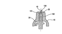
図2乃至4は、本発明の第1の実施の形態の変形例を示している。この第1の実施の形態の変形例によれば、スプレー開口部45が収められたスプレーヘッド40の端部は、収縮された形でスリーブ150を形成しており、当該スリーブ150の中をオブチュレータ38が軸方向にスライド移動する。効果的な構成として、このオブチュレータ38は、図1から見て取れるように、第2のピストン34と共に1つの部品の形で実装することができる。スリーブ150は、好ましい構成としてスプレーヘッド40の底部に共に1つの部品の形で実装され、当該スリーブ150にはスプレープロフィール100が収容されている。このスプレープロフィール100は渦チャンバ101を有し、当該渦チャンバはスプレー開口部45のすぐ上流に置かれ、投与位置においてスプレー開口部45に接続される。スプレープロフィール100は少なくとも1つの非径方向チャネル110をさらに有し、2つの非径方向チャネルがポンプの中心軸Xの周囲に相互に対称となる形で置かれることが好ましい。明らかなように、チャネル110の数はいくつであっても考え得る。これらの非径方向チャネル110は、製品の投与時に渦チャンバ101に接続される。図2乃至4から見て取れるように、非径方向チャネルは、効果的な構成としてスリーブ150の側壁の中に少なくとも部分的に実装されており、側壁の高さ全体に渡って実装されるのが好ましい。これにより、前記ヘッドに部品を付け加えることなく前記スプレープロフィールを極めて直接的または容易な方法で実装することができる。この実施の形態の変形例において、図3および4に示された閉鎖位置での渦チャンバ101の容積はゼロにはならず、前記オブチュレータ38は、実際、前記渦チャンバ101の内部で軸方向に移動する。非径方向チャネル110にポンプチャンバ20の一部分が形成され、ポンプチャンバ20の出口弁を形成するオブチュレータ38は、これが開いた際に、ポンプチャンバ20に格納された製品がスプレー開口部45からスプレーの形で投与される、ということを可能にする。
2 to 4 show a modification of the first embodiment of the present invention. According to the modification of the first embodiment, the end of the
図5および6は、実施の形態の変形例を示している。これらの図でも、軸方向スリーブ150は、やはりヘッド40の底部に単一部品の形で実装されているが、前記底部に対し突き出した形となっている。同様に、オブチュレータ38もわずかに異なった形で実装されている。具体的に言えば、オブチュレータ38は栓部品そのもので成り、当該栓部品は中央に位置し、スプレー開口部45と直接的に作用し合うだけでなく、前記栓部品を取り囲み、前記軸方向スリーブ150の中でスライド移動する周縁リップとも直接的に作用し合う。また、非径方向チャネル110は、閉鎖位置において前記オブチュレータ38により閉じられる軸方向スリーブの上端部分を除いて、軸方向スリーブの高さのほぼ全体に渡って延びている。この実施の形態において、閉鎖位置での渦チャンバ101の容積はほぼゼロで、渦チャンバが生じるのは、オブチュレータ38がその開放位置の方へ移動する間である。この時、渦チャンバは非径方向チャネル110に接続されて製品がスプレーされることが可能となる。
5 and 6 show a modification of the embodiment. Also in these figures, the
図7および8は、別の実施の形態の変形例を示している。これらの図では、オブチュレータ38はスリーブ150に取り付けられ、閉鎖位置におけるアレージまたはデッドボリュームを減少させる。さらに、前記少なくとも1つの非径方向チャネル110は、製品を渦チャンバ101の中に移動させるよう、スリーブ150の側壁において傾いた形としてもよい。
7 and 8 show a modification of another embodiment. In these figures,
図9(a)および図10(b)はさらに別の実施の形態の変形例を示している。この変形例では、スリーブ150は実際的にはその高さ全体に渡って分割されており、分割された部分のそれぞれによって非径方向チャネル110が形成されている。図9(b)および図10(b)の水平断面図は、閉鎖位置においてオブチュレータがアレージを埋めている様子、逆に、スプレー位置においてスプレー開口部45と非径方向チャネル110とが開いている様子を示している。
FIG. 9A and FIG. 10B show a modification of another embodiment. In this variation, the
本発明の実施形では、効果的な構成として、ヘッドの底部に設けられた軸方向スリーブの高さのほぼ全体に渡って実装する形でスプレーチャネルを設ける。この実施形の効果は、スプレーヘッド40の端部にあり、従来はこうした部位に存在する壁の薄さが原因となって比較的脆かったそのスプレープロフィールの製造が容易になる、という点である。特に、本発明により、スプレー開口部45を有する前記軸方向スリーブ150の底壁にチャネルを設ける必要がなくなる。それどころか逆に、オブチュレータが開放位置にある際は、図6に示されるように、軸方向スリーブ150のそうした底面全体が渦チャンバ101を形成する。
In the embodiment of the present invention, as an effective configuration, the spray channel is provided so as to be mounted over almost the entire height of the axial sleeve provided at the bottom of the head. The effect of this embodiment is at the end of the
ここまで、本発明について、その2つの実施の形態の変形例を参照しながら説明してきたが、理解されるように、本発明は図示された例に限定されるものではなく、当業者であれば、本特許請求の範囲によって規定される本発明の趣旨から逸脱しない形で、本発明に全ての効果的な変更を施すことが可能である。 So far, the present invention has been described with reference to the variations of the two embodiments, but as will be understood, the present invention is not limited to the illustrated examples, and those skilled in the art will understand. Thus, it is possible to make all the effective changes to the present invention without departing from the spirit of the present invention defined by the claims.
Claims (9)
スプレー開口部(45)と当該スプレー開口部(45)の上流にあるスプレープロフィール(100)とを有し、前記スプレープロフィールは、流体製品のスプレー時に前記スプレー開口部(45)に接続される渦チャンバ(101)と前記渦チャンバ(101)に接続される少なくとも1つの非径方向チャネル(110)とを有し、前記スプレープロフィール(100)は前記スプレーヘッド(40)の底部に実装され、オブチュレータ(38)は、前記スプレー開口部(45)の閉鎖位置と前記スプレー開口部(45)の開放位置との間で移動可能および/あるいは変形可能である、という形で前記スプレー開口部(45)と直接的に作用し合い、
前記スプレープロフィール(100)が収容された軸方向の中空スリーブ(150)を有し、前記オブチュレータ(38)は前記中空スリーブ(150)の中で少なくとも部分的に軸方向に移動可能および/あるいは変形可能で、スプレープロフィール(100)の前記少なくとも1つの非径方向チャネル(110)は、少なくとも部分的に前記中空スリーブ(150)の側壁の中で傾いた形で延びている
ことを特徴とする流体製品スプレーヘッド(40)。A fluid product spray head (40) comprising:
A spray opening (45) and a spray profile (100) upstream of said spray opening (45), said spray profile being a vortex connected to said spray opening (45) when spraying a fluid product And having at least one non-radial channel (110) connected to the vortex chamber (101), the spray profile (100) being mounted at the bottom of the spray head (40) The spray opening (45) is movable and / or deformable between a closed position of the spray opening (45) and an open position of the spray opening (45). Interact directly with
The spray profile (100) has an axial hollow sleeve (150) in which the obturator (38) is at least partially axially movable and / or deformed within the hollow sleeve (150). possible, the at least one non-radial channel of the spray profile (100) (110), the fluid, characterized in that extending in the form of inclined in the side wall at least in part on the hollow sleeve (150) Product spray head (40).
を特徴とする請求項1に記載の流体製品スプレーヘッド。The at least one non-radial channel (110) extends over substantially the entire axial height of the axial sleeve (150);
The fluid product spray head of claim 1.
を特徴とする請求項1または2に記載の流体製品スプレーヘッド。In the closed position of the obturator (38), the volume of the vortex chamber (101) is zero, and the obturator (38) moves and / or deforms towards its open position, thereby upstream of the spray opening (45). and that said vortex chamber downstream of the at least one non-radial channel (110) (101) is formed,
A fluid product spray head according to claim 1 or 2 .
を特徴とする請求項1または2に記載の流体製品スプレーヘッド。In the closed position of the obturator (38), the volume of the vortex chamber (101) is zero, the obturator (38) runs longitudinally through the vortex chamber (101) and closes the spray opening (45);
A fluid product spray head according to claim 1 or 2 .
を特徴とする請求項1乃至4のいずれか一項に記載の流体製品スプレーヘッド。The spray profile (100) has two non-radial channels (110), the non-radial channels (110) being placed symmetrically with respect to the central axis (X) of the pump;
Fluid product spray head according to any one of claims 1 to 4, characterized in.
を特徴とする請求項1乃至5のいずれか一項に記載の流体製品スプレーヘッド。The axial sleeve (150) is formed in a single piece at the bottom of the spray head (40);
Fluid product spray head according to any one of claims 1 to 5, characterized in.
特徴となるのは、
請求項1乃至6のいずれか一項に記載のスプレーヘッド(40)を有することである、
という流体製品投与ポンプ。A fluid product dosing pump comprising:
The feature is
It has a spray head (40) according to any one of claims 1 to 6 .
A fluid product dosing pump.
を特徴とする請求項7に記載の流体製品投与ポンプ。Having a pump chamber (20) defining the dose of product released at each drive, said pump chamber (20) being placed immediately upstream of said spray opening (45), said obturator (38) being connected to said pump Sliding in the chamber (20);
The fluid product dosing pump of claim 7 .
特徴となるのは、
タンク(60)と請求項7または8に記載のポンプとを有することである、
という流体製品投与装置。A fluid product dispensing device comprising:
The feature is
Having a tank (60) and a pump according to claim 7 or 8 .
A fluid product dispensing device.
Applications Claiming Priority (3)
| Application Number | Priority Date | Filing Date | Title |
|---|---|---|---|
| FR0313095A FR2862009B1 (en) | 2003-11-07 | 2003-11-07 | FLUID PRODUCT SPRAYING HEAD AND DELIVERY PUMP COMPRISING SUCH A HEAD. |
| FR0313095 | 2003-11-07 | ||
| PCT/FR2004/050569 WO2005045292A1 (en) | 2003-11-07 | 2004-11-05 | Fluid product spray head and distributing pump comprising this spray head |
Publications (2)
| Publication Number | Publication Date |
|---|---|
| JP2007515266A JP2007515266A (en) | 2007-06-14 |
| JP4847871B2 true JP4847871B2 (en) | 2011-12-28 |
Family
ID=34508328
Family Applications (1)
| Application Number | Title | Priority Date | Filing Date |
|---|---|---|---|
| JP2006537394A Expired - Fee Related JP4847871B2 (en) | 2003-11-07 | 2004-11-05 | Fluid product spray head and dosing pump having such a spray head |
Country Status (7)
| Country | Link |
|---|---|
| US (1) | US7448559B2 (en) |
| EP (1) | EP1697670B1 (en) |
| JP (1) | JP4847871B2 (en) |
| CN (1) | CN100487292C (en) |
| DE (1) | DE602004011986T2 (en) |
| FR (1) | FR2862009B1 (en) |
| WO (1) | WO2005045292A1 (en) |
Families Citing this family (24)
| Publication number | Priority date | Publication date | Assignee | Title |
|---|---|---|---|---|
| ATE426460T1 (en) * | 2002-08-06 | 2009-04-15 | Glaxo Group Ltd | DISPENSING DEVICE |
| FR2862009B1 (en) * | 2003-11-07 | 2007-01-05 | Valois Sas | FLUID PRODUCT SPRAYING HEAD AND DELIVERY PUMP COMPRISING SUCH A HEAD. |
| FR2884157B1 (en) * | 2005-04-08 | 2007-07-06 | Airlessystems Soc Par Actions | HEAD OF DISTRIBUTION |
| FR2892158B1 (en) * | 2005-10-17 | 2011-10-21 | Valois Sas | FLUID PRODUCT DELIVERY PUMP |
| DE102006008874B4 (en) | 2006-02-21 | 2012-06-21 | Ing. Erich Pfeiffer Gmbh | Metering device with a manually operable pumping device |
| ES2265789B1 (en) | 2006-03-02 | 2008-02-01 | Saint-Gobain Calmar, S.A. | FLASHED PUMVERIZING PUMP. |
| FR2898818B1 (en) * | 2006-03-22 | 2008-08-22 | Valois Sas | FLUID PRODUCT DELIVERY PUMP |
| GB0610666D0 (en) * | 2006-05-30 | 2006-07-05 | Glaxo Group Ltd | Fluid dispenser |
| ITMO20060252A1 (en) * | 2006-08-04 | 2008-02-05 | Mrp Medical Res & Promotion Es | BOTTLE FOR FLUID CONTAINMENT, PARTICULARLY FOR PHARMACEUTICAL OR SIMILAR PRODUCTS |
| FR2905941B1 (en) * | 2006-09-20 | 2011-02-11 | Valois Sas | FLUID PRODUCT DISTRIBUTION ASSEMBLY AND DISPENSER HAVING SUCH A DISPENSING ASSEMBLY |
| NZ581439A (en) | 2007-05-30 | 2013-03-28 | Fluid dispenser with a piston sealingly movable in a dosing chamber but only in sealing contact with a narrower first section during a part of the stroke. | |
| FR2933680B1 (en) * | 2008-07-11 | 2013-01-18 | Valois Sa | FLUID PRODUCT DELIVERY PUMP |
| DE102009006428B4 (en) * | 2009-01-23 | 2011-06-22 | Ing. Erich Pfeiffer GmbH, 78315 | discharge |
| US20110031328A1 (en) * | 2009-08-06 | 2011-02-10 | Greg Rundle | Nozzle apparatus for dispersing droplets of flowable material |
| WO2011158881A1 (en) | 2010-06-15 | 2011-12-22 | 株式会社ダイゾー | Nozzle hole mechanism |
| FR2962351B1 (en) | 2010-07-09 | 2015-01-16 | Valois Sas | SPRAY HEAD FOR DEVICE FOR DISPENSING FLUID. |
| US10154923B2 (en) | 2010-07-15 | 2018-12-18 | Eyenovia, Inc. | Drop generating device |
| FR2973015B1 (en) * | 2011-03-25 | 2013-04-26 | Valois Sas | FLUID PRODUCT DELIVERY PUMP. |
| JP6329130B2 (en) | 2012-04-10 | 2018-05-30 | アイノビア,インコーポレイティド | Spray ejector mechanism, device that provides charge separation and controllable droplet charge, and low dose eye drops |
| CN109011046B (en) * | 2012-04-20 | 2021-10-01 | 艾诺维亚股份有限公司 | Device for delivering a fluid to a target |
| US9463486B2 (en) | 2012-05-14 | 2016-10-11 | Eyenovia, Inc. | Laminar flow droplet generator device and methods of use |
| MX2014013962A (en) | 2012-05-15 | 2015-06-17 | Eyenovia Inc | Ejector devices, methods, drivers, and circuits therefor. |
| EP3634550A4 (en) | 2017-06-10 | 2021-03-03 | Eyenovia, Inc. | Methods and devices for handling a fluid and delivering the fluid to the eye |
| FR3126287A1 (en) | 2021-08-30 | 2023-03-03 | L'oreal | Device for conditioning a refill equipped with a pump |
Citations (7)
| Publication number | Priority date | Publication date | Assignee | Title |
|---|---|---|---|---|
| US3990640A (en) * | 1974-12-20 | 1976-11-09 | Laauwe Robert H | Actuator for aerosol valve stems |
| JPH01170462A (en) * | 1987-12-24 | 1989-07-05 | Sekisui Chem Co Ltd | Granular deodorant |
| JPH0746358B2 (en) * | 1988-01-13 | 1995-05-17 | 三洋電機株式会社 | Connectivity tester |
| JP2002542019A (en) * | 1999-04-20 | 2002-12-10 | バルワー エス.アー. | Fluid spray head with sealing member |
| JP2004008951A (en) * | 2002-06-07 | 2004-01-15 | Mitani Valve Co Ltd | Ejection button |
| JP2004513301A (en) * | 2000-10-23 | 2004-04-30 | バルワー エス.アー.エス. | Dosing head and fluid dispenser having the dosing head |
| EP1697670B1 (en) * | 2003-11-07 | 2008-02-20 | Valois SAS | Fluid product spray head and distributing pump comprising this spray head |
Family Cites Families (8)
| Publication number | Priority date | Publication date | Assignee | Title |
|---|---|---|---|---|
| US3437270A (en) * | 1968-03-12 | 1969-04-08 | Risdon Mfg Co | Self-sealing spray-actuator button |
| US3545682A (en) * | 1968-10-09 | 1970-12-08 | Walter C Beard | Dispensing device |
| JPH0612850Y2 (en) * | 1988-05-18 | 1994-04-06 | 誠一 北林 | Spray nozzle of atomizer |
| US5273191A (en) * | 1991-08-20 | 1993-12-28 | Philip Meshberg | Dispensing head for a squeeze dispenser |
| DE19622124A1 (en) * | 1996-06-01 | 1997-12-04 | Alfred Von Schuckmann | Device for applying liquids |
| FR2773784B1 (en) * | 1998-01-16 | 2000-03-24 | Valois Sa | SPRAY HEAD FOR A FLUID PRODUCT DISPENSER |
| US6543703B2 (en) * | 2000-12-26 | 2003-04-08 | William S. Blake | Flexible face non-clogging actuator assembly |
| FR2832079B1 (en) * | 2001-11-14 | 2004-07-30 | Valois Sa | DISPENSING HEAD AND FLUID PRODUCT DISPENSER COMPRISING SUCH A DISPENSING HEAD |
-
2003
- 2003-11-07 FR FR0313095A patent/FR2862009B1/en not_active Expired - Fee Related
-
2004
- 2004-11-05 EP EP04805812A patent/EP1697670B1/en not_active Ceased
- 2004-11-05 CN CNB2004800355662A patent/CN100487292C/en not_active Expired - Fee Related
- 2004-11-05 JP JP2006537394A patent/JP4847871B2/en not_active Expired - Fee Related
- 2004-11-05 WO PCT/FR2004/050569 patent/WO2005045292A1/en active IP Right Grant
- 2004-11-05 DE DE602004011986T patent/DE602004011986T2/en active Active
- 2004-11-05 US US10/578,225 patent/US7448559B2/en not_active Expired - Fee Related
Patent Citations (8)
| Publication number | Priority date | Publication date | Assignee | Title |
|---|---|---|---|---|
| US3990640A (en) * | 1974-12-20 | 1976-11-09 | Laauwe Robert H | Actuator for aerosol valve stems |
| JPH01170462A (en) * | 1987-12-24 | 1989-07-05 | Sekisui Chem Co Ltd | Granular deodorant |
| JPH0746358B2 (en) * | 1988-01-13 | 1995-05-17 | 三洋電機株式会社 | Connectivity tester |
| JP2002542019A (en) * | 1999-04-20 | 2002-12-10 | バルワー エス.アー. | Fluid spray head with sealing member |
| JP2004513301A (en) * | 2000-10-23 | 2004-04-30 | バルワー エス.アー.エス. | Dosing head and fluid dispenser having the dosing head |
| JP2004008951A (en) * | 2002-06-07 | 2004-01-15 | Mitani Valve Co Ltd | Ejection button |
| EP1697670B1 (en) * | 2003-11-07 | 2008-02-20 | Valois SAS | Fluid product spray head and distributing pump comprising this spray head |
| US7448559B2 (en) * | 2003-11-07 | 2008-11-11 | Valois S.A.S. | Fluid product spray head and distributing pump comprising this spray head |
Also Published As
| Publication number | Publication date |
|---|---|
| JP2007515266A (en) | 2007-06-14 |
| EP1697670A1 (en) | 2006-09-06 |
| US20070131799A1 (en) | 2007-06-14 |
| FR2862009B1 (en) | 2007-01-05 |
| CN1886612A (en) | 2006-12-27 |
| US7448559B2 (en) | 2008-11-11 |
| WO2005045292A1 (en) | 2005-05-19 |
| EP1697670B1 (en) | 2008-02-20 |
| DE602004011986D1 (en) | 2008-04-03 |
| FR2862009A1 (en) | 2005-05-13 |
| CN100487292C (en) | 2009-05-13 |
| DE602004011986T2 (en) | 2009-02-26 |
Similar Documents
| Publication | Publication Date | Title |
|---|---|---|
| JP4847871B2 (en) | Fluid product spray head and dosing pump having such a spray head | |
| US4230242A (en) | Triple seal valve member for an atomizing pump dispenser | |
| US6516976B2 (en) | Dosing pump for liquid dispensers | |
| JP4918096B2 (en) | Fluid dosing pump | |
| US7267251B2 (en) | Draw back pump | |
| JP3679977B2 (en) | Trigger-actuated pump sprayer and its discharge valve assembly | |
| US6443370B1 (en) | Spray head for a liquid-product distributor | |
| JPH02180178A (en) | Paste spender | |
| CN103917302B (en) | Fluid dispensing device | |
| US7780042B2 (en) | Fluid dispenser pump | |
| GB2286230A (en) | Dispensing apparatus | |
| US4315582A (en) | Universal sequential dispensing pump system free of external check valves and having venting capability | |
| US7029249B2 (en) | Electronic micro-pump | |
| CN103492086B (en) | Fluid product dispensing pump and the device fluid dispensing product including this pump | |
| JP4891776B2 (en) | Fluid product dosing pump | |
| ITMI941061A1 (en) | NEBULIZED PRESSURE FLUID DISPENSER, PROVIDED WITH MOBILE SHUTTER FOR PRESSURE FLUID ACTION | |
| US7967171B2 (en) | Air foaming pump trigger sprayer | |
| JP7411661B2 (en) | Device for dispensing fluid products | |
| JP4825678B2 (en) | Fluid product dosing pump | |
| JPH04282084A (en) | Discharge device for medium | |
| JPH0761485A (en) | Medium discharging device | |
| JP2011527213A (en) | Fluid dispenser device | |
| ITMI951544A1 (en) | ATOMIZED LIQUID DISPENSER | |
| US7597218B2 (en) | Pump with mechanical means for effective priming and drip prevention | |
| KR101551192B1 (en) | Medicanent dispenser |
Legal Events
| Date | Code | Title | Description |
|---|---|---|---|
| A621 | Written request for application examination |
Free format text: JAPANESE INTERMEDIATE CODE: A621 Effective date: 20070926 |
|
| A131 | Notification of reasons for refusal |
Free format text: JAPANESE INTERMEDIATE CODE: A131 Effective date: 20101214 |
|
| TRDD | Decision of grant or rejection written | ||
| A01 | Written decision to grant a patent or to grant a registration (utility model) |
Free format text: JAPANESE INTERMEDIATE CODE: A01 Effective date: 20110927 |
|
| A01 | Written decision to grant a patent or to grant a registration (utility model) |
Free format text: JAPANESE INTERMEDIATE CODE: A01 |
|
| A61 | First payment of annual fees (during grant procedure) |
Free format text: JAPANESE INTERMEDIATE CODE: A61 Effective date: 20111014 |
|
| FPAY | Renewal fee payment (event date is renewal date of database) |
Free format text: PAYMENT UNTIL: 20141021 Year of fee payment: 3 |
|
| R150 | Certificate of patent or registration of utility model |
Ref document number: 4847871 Country of ref document: JP Free format text: JAPANESE INTERMEDIATE CODE: R150 Free format text: JAPANESE INTERMEDIATE CODE: R150 |
|
| S533 | Written request for registration of change of name |
Free format text: JAPANESE INTERMEDIATE CODE: R313533 |
|
| R350 | Written notification of registration of transfer |
Free format text: JAPANESE INTERMEDIATE CODE: R350 |
|
| R250 | Receipt of annual fees |
Free format text: JAPANESE INTERMEDIATE CODE: R250 |
|
| R250 | Receipt of annual fees |
Free format text: JAPANESE INTERMEDIATE CODE: R250 |
|
| R250 | Receipt of annual fees |
Free format text: JAPANESE INTERMEDIATE CODE: R250 |
|
| R250 | Receipt of annual fees |
Free format text: JAPANESE INTERMEDIATE CODE: R250 |
|
| R250 | Receipt of annual fees |
Free format text: JAPANESE INTERMEDIATE CODE: R250 |
|
| R250 | Receipt of annual fees |
Free format text: JAPANESE INTERMEDIATE CODE: R250 |
|
| LAPS | Cancellation because of no payment of annual fees |