JP4845700B2 - Image forming apparatus and control method thereof - Google Patents
Image forming apparatus and control method thereof Download PDFInfo
- Publication number
- JP4845700B2 JP4845700B2 JP2006336382A JP2006336382A JP4845700B2 JP 4845700 B2 JP4845700 B2 JP 4845700B2 JP 2006336382 A JP2006336382 A JP 2006336382A JP 2006336382 A JP2006336382 A JP 2006336382A JP 4845700 B2 JP4845700 B2 JP 4845700B2
- Authority
- JP
- Japan
- Prior art keywords
- workflow
- data
- forming apparatus
- input
- image
- Prior art date
- Legal status (The legal status is an assumption and is not a legal conclusion. Google has not performed a legal analysis and makes no representation as to the accuracy of the status listed.)
- Expired - Fee Related
Links
Images


Classifications
-
- H—ELECTRICITY
- H04—ELECTRIC COMMUNICATION TECHNIQUE
- H04N—PICTORIAL COMMUNICATION, e.g. TELEVISION
- H04N1/00—Scanning, transmission or reproduction of documents or the like, e.g. facsimile transmission; Details thereof
- H04N1/32—Circuits or arrangements for control or supervision between transmitter and receiver or between image input and image output device, e.g. between a still-image camera and its memory or between a still-image camera and a printer device
- H04N1/32561—Circuits or arrangements for control or supervision between transmitter and receiver or between image input and image output device, e.g. between a still-image camera and its memory or between a still-image camera and a printer device using a programmed control device, e.g. a microprocessor
-
- H—ELECTRICITY
- H04—ELECTRIC COMMUNICATION TECHNIQUE
- H04N—PICTORIAL COMMUNICATION, e.g. TELEVISION
- H04N1/00—Scanning, transmission or reproduction of documents or the like, e.g. facsimile transmission; Details thereof
- H04N1/00912—Arrangements for controlling a still picture apparatus or components thereof not otherwise provided for
- H04N1/0096—Simultaneous or quasi-simultaneous functioning of a plurality of operations
-
- H—ELECTRICITY
- H04—ELECTRIC COMMUNICATION TECHNIQUE
- H04N—PICTORIAL COMMUNICATION, e.g. TELEVISION
- H04N1/00—Scanning, transmission or reproduction of documents or the like, e.g. facsimile transmission; Details thereof
- H04N1/32—Circuits or arrangements for control or supervision between transmitter and receiver or between image input and image output device, e.g. between a still-image camera and its memory or between a still-image camera and a printer device
- H04N1/32561—Circuits or arrangements for control or supervision between transmitter and receiver or between image input and image output device, e.g. between a still-image camera and its memory or between a still-image camera and a printer device using a programmed control device, e.g. a microprocessor
- H04N1/32598—Bus based systems
- H04N1/32603—Multi-bus systems
-
- H—ELECTRICITY
- H04—ELECTRIC COMMUNICATION TECHNIQUE
- H04N—PICTORIAL COMMUNICATION, e.g. TELEVISION
- H04N2201/00—Indexing scheme relating to scanning, transmission or reproduction of documents or the like, and to details thereof
- H04N2201/0077—Types of the still picture apparatus
- H04N2201/0094—Multifunctional device, i.e. a device capable of all of reading, reproducing, copying, facsimile transception, file transception
Landscapes
- Engineering & Computer Science (AREA)
- Multimedia (AREA)
- Signal Processing (AREA)
- Computer Hardware Design (AREA)
- Microelectronics & Electronic Packaging (AREA)
- Facsimiles In General (AREA)
- Accessory Devices And Overall Control Thereof (AREA)
- Control Or Security For Electrophotography (AREA)
Description
本発明は、画像形成に関する機能を実現する複数の処理を連続処理として規定するワークフローに従って前記画像形成を行う画像形成装置及びその制御方法に関する。 The present invention relates to an image forming apparatus that performs image formation according to a workflow that defines a plurality of processes that realize functions relating to image formation as continuous processes, and a control method thereof.
印刷業務のワークフロー(WF)において、WFが一度定義されると、そのWFは1人のユーザだけでなく、複数のユーザから複数回繰り返し実行される。そのとき、各ユーザはそのWFに定義されている処理工程を繰り返し実行することになる。 In a printing workflow (WF), once a WF is defined, the WF is repeatedly executed not only by one user but also by a plurality of users. At that time, each user repeatedly executes the processing steps defined in the WF.
しかしながら、定義されたWFの処理工程には、何度も繰り返す必要のない処理工程も存在する。例えば、同じ印刷データを使用する場合に、印刷データを展開(RIP)する処理は、RIP後のデータを記憶しておくことにより、そのRIP処理に関する処理工程を省略することが可能となる。 However, there are processing steps that do not need to be repeated many times in the defined WF processing steps. For example, when the same print data is used, the process for developing (RIP) the print data can store the post-RIP data, thereby omitting the processing steps related to the RIP process.
上述の技術を用いることで、WFを効率的に実行することが可能となるが、保存処理は自動的に行われず、印刷データを保存するタイミングや保存形式、保存場所などはユーザが指定しなければならない。 Although the WF can be efficiently executed by using the above-described technology, the saving process is not automatically performed, and the user must specify the timing, saving format, saving location, etc. for saving the print data. I must.
また、保存されている印刷データを用いて同じ印刷を行うためには、ユーザは保存した印刷データを管理しておく必要がある。つまり、ユーザ自身が過去に印刷したことを記憶していなければ、過去に行った処理(例えばRIP)を繰返し行わなければならず、無駄な処理が発生し、WFの処理効率の低下を招くおそれがある。 Further, in order to perform the same printing using the stored print data, the user needs to manage the stored print data. In other words, if the user himself / herself does not remember that he / she has printed in the past, the past processing (for example, RIP) must be repeated, and wasteful processing may occur, leading to a reduction in WF processing efficiency. There is.
この問題を解決し、印刷処理の利便性を向上させることを目的として、印刷データを再利用する技術が開示されている(例えば、特許文献1参照)。特許文献1のドキュメント管理システムは、印刷データの再利用に関して、印刷データ及び印刷データに対する処理内容の履歴を記録し、出力指示された印刷データの出力履歴が存在するかを判定する。そして、履歴が存在すると判定すると、印刷データがいつ誰から出力されたかや保存場所を表示し、過去に印刷されたことがあることを表示する。
しかしながら、上述した特許文献1に記載の技術では、処理された全てのデータが保存対象となるため、特許文献1に記載のドキュメント管理部は、再利用できない可能性を有するデータであっても保存していた。
However, in the technique described in
例えば、スキャナを用いて入力されたデータは、スキャン時の読み取り不正により再利用できない可能性がある。しかしながら、特許文献1に記載の技術では、ドキュメント管理部が、操作の種類と当該操作結果のデータを常に格納するため、再利用できないデータが格納されてしまう。
For example, there is a possibility that data input using a scanner cannot be reused due to incorrect reading at the time of scanning. However, in the technique described in
その結果、ユーザが再利用できないようなデータを用いて画像形成処理を実行した場合、画像形成処理結果はユーザの意図する出力結果ではないために、画像形成処理に関わる処理を入力工程からやり直す必要があり、無駄が発生する。また、保存された印刷データを使って印刷を行うためには、ユーザは保存した印刷データを管理しておく必要があり、ユーザにとって負担となる。 As a result, when the image formation process is executed using data that cannot be reused by the user, the image formation process result is not the output result intended by the user, so the process related to the image formation process needs to be repeated from the input process. There is a waste. Further, in order to perform printing using the saved print data, the user needs to manage the saved print data, which is a burden on the user.
本発明は、ワークフローを実行する際に、入力工程にて入力された入力データに従って入力データに基づく処理済みデータを選択的に保存することで、複数の処理を連続処理する際に、無駄な処理を行うことなく、処理効率を向上させることを目的とする。 The present invention selectively saves processed data based on input data in accordance with the input data input in the input process when executing the workflow, thereby performing wasteful processing when processing a plurality of processes continuously. The object is to improve the processing efficiency without performing the above.
本発明は、画像形成に関する機能を実現する複数の処理を連続処理として規定するワークフローに従って前記画像形成を行う画像形成装置であって、前記ワークフローの実行を指示する指示手段と、前記ワークフローに含まれる入力工程によって入力された入力データの発行元に従って、当該ワークフローによって生成された当該入力データに基づく処理済みデータを保存するか否かを判定する第1判定手段と、前記第1判定手段によって保存すると判定された場合、前記ワークフローを実行することで得られる処理済みデータを記憶手段に保存する保存処理を含む複数の処理について連続処理を実行し、前記第1判定手段によって保存しないと判定した場合、前記ワークフローを実行することで得られる処理済みデータを保存することなく、複数の処理について連続処理を実行するワークフロー制御手段と、を有することを特徴とする。 The present invention is an image forming apparatus that performs the image formation according to a workflow that defines a plurality of processes that realize functions relating to image formation as continuous processes, and includes an instruction unit that instructs execution of the workflow, and the workflow According to the issuer of the input data input in the input step, a first determination unit that determines whether to save the processed data based on the input data generated by the workflow, and the first determination unit stores When it is determined, when it is determined not to save by the first determination unit, continuous processing is performed for a plurality of processes including a storage process for storing processed data obtained by executing the workflow in the storage unit, Without saving the processed data obtained by executing the workflow And having a workflow control means for executing a continuous process for a plurality of processes, the.
また、本発明は、画像形成に関する機能を実現する複数の処理を連続処理として規定するワークフローに従って前記画像形成を行う画像形成装置の制御方法であって、指示手段が、前記ワークフローの実行を指示する指示工程と、第1判定手段が、前記ワークフローに含まれる入力工程によって入力された入力データの発行元に従って、当該ワークフローによって生成された当該入力データに基づく処理済みデータを保存するか否かを判定する第1判定工程と、ワークフロー制御手段が、前記第1判定工程において保存すると判定された場合、前記ワークフローを実行することで得られる処理済みデータを記憶手段に保存する保存処理を含む複数の処理について連続処理を実行し、前記第1判定工程において保存しないと判定した場合、前記ワークフローを実行することで得られる処理済みデータを保存することなく、複数の処理について連続処理を実行するワークフロー制御工程と、を有することを特徴とする。 The present invention is also a control method for an image forming apparatus that performs the image formation in accordance with a workflow that defines a plurality of processes that realize functions relating to image formation as continuous processes, and an instruction unit instructs execution of the workflow. The instruction step and the first determination means determine whether to save the processed data based on the input data generated by the workflow according to the issuer of the input data input by the input step included in the workflow plurality including a first determination step, the workflow control unit, when it is determined that the stored at said first determination step, the storage process for storing the processed data obtained by executing the workflow storage means for If a running continuous process for processing, determines not to store at the first determination step, the Without storing the processed data obtained by performing the Kufuro, and having a workflow control performing a continuous treatment for a plurality of processes, the.
本発明によれば、画像形成に関数する機能を実現する複数の処理を連続処理する際に、無駄な処理を行うことなく、処理効率を向上させることができる。 According to the present invention, it is possible to improve processing efficiency without performing useless processing when continuously performing a plurality of processes for realizing a function that functions for image formation.
以下、図面を参照しながら発明を実施するための最良の形態について詳細に説明する。 The best mode for carrying out the invention will be described below in detail with reference to the drawings.
[第1の実施形態]
まず、複数の画像形成装置、サーバ及びクライアントとして機能するコンピュータなどがネットワーク(LAN)を介して接続されるシステムの構成及びワークフローに従って印刷データを出力する画像形成装置の構成を、図1〜図5を用いて説明する。
[First Embodiment]
First, a configuration of a system in which a plurality of image forming apparatuses, a computer functioning as a server, a client, and the like are connected via a network (LAN) and a configuration of an image forming apparatus that outputs print data according to a workflow are illustrated in FIGS. Will be described.
(システムの構成)
図1は、第1の実施形態におけるネットワークシステムの構成の一例を示す図である。図1に示す例では、画像形成装置は、データ送受信機能を有する複写機である。ここで、複写機1001は、複写機1001と同等の機能を持つ複写機1002、ファクシミリ装置1003、データベース/メールサーバ1004、クライアントコンピュータ1005と共に、LAN1006に接続されている。また、複写機1001は、公衆回線1008を介してファクシミリ装置1007とファックスを送受信可能である。
(System configuration)
FIG. 1 is a diagram illustrating an example of a configuration of a network system according to the first embodiment. In the example shown in FIG. 1, the image forming apparatus is a copying machine having a data transmission / reception function. Here, the copier 1001 is connected to a
複写機1001は、コピー機能、ファクシミリ機能を有すると共に、原稿を読み取り、読み取って得られた画像データをLAN1006上の各装置に送信するデータ送信機能を有する。また、複写機1001は、PDL(Page Description Language)機能を有し、LAN1006上のクライアントコンピュータ1005から指示されたPDL画像を受信して印刷を行う。複写機1001は、複写機1001で読み取った画像やLAN1006上のクライアントコンピュータ1005から指示されたPDL画像を複写機1001内のハードディスクの指定したボックス領域に保存する。そして、複写機1001はボックス領域に保存された画像を印刷することができる。このボックス領域については、更に後述する。
The copying machine 1001 has a copy function and a facsimile function, and also has a data transmission function for reading a document and transmitting image data obtained by reading to each device on the
また、複写機1001は、複写機1002が読み取った画像データを、LAN1006を介して受信し、その画像データを複写機1001内のハードディスク等に保存、或いは印刷出力する。また、複写機1001は、クライアントコンピュータ1005及びデータベース/メールサーバ1004の画像データを、LAN1006を介して受信し、その画像データを複写機1001内に保存、或いは印刷出力する。
The copier 1001 receives the image data read by the copier 1002 via the
ファクシミリ装置1003は、複写機1001が読み取った画像データを、LAN1006を介して受信し、その画像データをファックスデータに変換して送信する。
The facsimile machine 1003 receives the image data read by the copying machine 1001 via the
データベース/メールサーバ1004は、複写機1001が読み取った画像データを、LAN1006を介して受信し、その画像データをデータベースに格納し、電子メールとして送信する機能を有するコンピュータである。
The database /
クライアントコンピュータ1005は、データベース/メールサーバ1004と接続し、データベース/メールサーバ1004から所望のデータを取得して画面上に表示する。また、複写機1001が読み取った画像データを、LAN1006を介して受信し、その画像データを加工、編集する。
The client computer 1005 connects to the database /
ファクシミリ装置1007は、複写機1001で読み取られ、ファックスデータに変換された画像を、公衆回線1008を介して受信し、その画像を印刷出力する。
The facsimile machine 1007 receives an image read by the copying machine 1001 and converted into fax data via the
図2は、複写機1001の主要部の構成を示すブロック図である。図2に示すように、複写機1001はコントローラユニット2000を含み、コントローラユニット2000には、画像入力機器であるスキャナ2070、画像出力機器であるプリンタ2095及び操作部2012が接続されている。コントローラユニット2000は、スキャナ2070で読み取られた画像データをプリンタ2095により印刷出力するコピー機能を実現するための制御を行う。また、LAN1006や公衆回線1008(WAN)に接続することにより、画像情報やデバイス情報の入出力を行うための制御を行う。
FIG. 2 is a block diagram showing the configuration of the main part of the copying machine 1001. As shown in FIG. 2, the copying machine 1001 includes a
コントローラユニット2000は、具体的には、CPU2001を有する。このCPU2001は、ROM2003に格納されているブートプログラムによってオペレーションシステム(OS)を立ち上げる。そして、OS上で、HDD(ハードディスクドライブ)2004に格納されているアプリケーションプログラムを実行することにより、各種処理を実行する。ここで、CPU2001の作業領域として、RAM2002が用いられる。このRAM2002は作業領域を提供すると共に、画像データを一時記憶するための画像メモリ領域を提供する。HDD2004は、後述するボックス領域を含み、ワークフローを実行するアプリケーションプログラムや画像データを格納する。
Specifically, the
CPU2001には、システムバス2007を介してROM2003、RAM2002、操作部I/F(インタフェース)2006、ネットワークI/F2010、モデム2050及びイメージバスI/F2005が接続される。
A
操作部I/F2006は、タッチパネルを有する操作部2012とのインタフェースであり、操作部2012に表示すべき画像データを操作部2012に対して出力する。また、操作部I/F2006は操作部2012においてユーザにより入力された情報をCPU2001に送出する。
An operation unit I /
次に、ネットワークI/F2010は、LAN1006に接続され、LAN1006を介してLAN1006上の各装置との間で情報の入出力を行う。モデム2050は、公衆回線1008に接続され、公衆回線1008を介して情報の入出力を行う。
Next, the network I /
イメージバスI/F2005は、システムバス2007と、画像データを高速で転送する画像バス2008とを接続し、データ形式を変換するためのバスブリッジである。画像バス2008は、PCIバス又はIEEE1394から構成される。画像バス2008上には、ラスタイメージプロセッサ(RIPと称す)2060、デバイスI/F2020、スキャナ画像処理部2080、プリンタ画像処理部2090、画像回転部2030、及び画像圧縮部2040が設けられる。
An image bus I / F 2005 is a bus bridge for connecting a
RIP2060は、PDLコードをビットマップイメージに展開するプロセッサである。デバイスI/F2020には、スキャナ2070及びプリンタ2095が接続され、デバイスI/F2020は画像データの同期系/非同期系の変換を行う。
The
スキャナ画像処理部2080は、スキャナ2070から入力された画像データに対して補正、加工、編集を行う。プリンタ画像処理部2090は、プリンタ2095へ出力する画像データに対してプリンタ2095に応じた補正、解像度変換などを行う。画像回転部2030は、画像データに対して回転を行う。画像圧縮部2040は、多値画像データをJPEGデータに、2値画像データをJBIG、MMR、MHなどのデータに圧縮すると共に、その伸張処理を行う。
A scanner
ここで、スキャナ2070及びプリンタ2095のハードウェア構成の一例を、図3を用いて説明する。
Here, an example of the hardware configuration of the
図3は、図2に示すスキャナ2070及びプリンタ2095のハードウェア構成を示す側断面図である。スキャナ2070とプリンタ2095とは、図3に示すように、一体的に構成されている。スキャナ2070には、原稿給紙ユニット250が搭載されている。原稿給紙ユニット250は、原稿を先頭から順に1枚ずつプラテンガラス211上へ給送し、各原稿の読取動作が終了する毎に、その原稿をプラテンガラス211から排出トレイ(図示せず)に排出する。また、スキャナ2070は、原稿がプラテンガラス211上に給送されると、ランプ212を点灯し、移動ユニット213の移動を開始する。この移動ユニット213の移動によりプラテンガラス211上の原稿に対する読取走査が行われる。この読取走査により原稿からの反射光が各ミラー214,215,216及びレンズ217を経てCCDイメージセンサ(CCDと称す)218に導かれ、CCD218の撮像面上に結像される。CCD218は、撮像面に結像された画像を電気信号に変換し、この電気信号に所定の処理が施された後、コントローラユニット2000に入力される。
FIG. 3 is a side sectional view showing a hardware configuration of the
プリンタ2095には、レーザドライバ321を有し、レーザドライバ321がコントローラユニット2000から入力された画像データに基づき、レーザ発光部322を駆動する。これにより、レーザ発光部322からは画像データに応じたレーザ光が発光され、このレーザ光が走査されながら感光ドラム323上に照射される。感光ドラム323上には、照射されたレーザ光により静電潜像が形成され、この静電潜像は現像器324から供給されたトナーによりトナー像として可視像化される。レーザ光の照射タイミングに同期して、各カセット311,312から記録紙が搬送路を介して感光ドラム323と転写部325との間に給紙され、感光ドラム323上のトナー像は転写部325により給紙された記録紙上に転写される。
The
トナー像が転写された記録紙は、搬送ベルトを介して定着ローラ対(加熱ローラと加圧ローラ)326に送られ、定着ローラ対326は、記録紙を熱圧し、記録紙上のトナー像を記録紙上に定着させる。この定着ローラ対326を通過した記録紙は、排紙ローラ対327により排紙ユニット330に排紙される。排紙ユニット330は、ソート、ステイプルなどの後処理を施すことが可能なシート処理装置からなる。
The recording paper onto which the toner image has been transferred is sent to a fixing roller pair (heating roller and pressure roller) 326 via a conveyance belt, and the fixing
また、両面記録モードが設定されている場合には、記録紙を排紙ローラ対327まで搬送した後に、排紙ローラ対327の回転方向を逆転させ、フラッパ328によって再給紙搬送路339へ導く。再給紙搬送路339に導かれた記録紙は、上述したタイミングで感光ドラム323と転写部325との間に再給紙され、この記録紙の裏面にトナー像が転写される。
When the duplex recording mode is set, after the recording sheet is conveyed to the
図4は、図2に示す操作部2012の構成の一例を示す平面図である。図4において、LCD表示部2013は、LCD上にタッチパネルシートが貼られた構造となっている。そして、複写機1001の操作画面を表示し、操作画面に表示されたキーが押されると、その位置情報をコントローラユニット2000のCPU2001に伝える。
FIG. 4 is a plan view showing an example of the configuration of the
スタートキー2014は、原稿の読み取り動作を開始する時などに用いられる。スタートキー2014の中央部には、緑と赤の2色LED2018が設けられ、その色によってスタートキー2014が使える状態にあるか否かを示す。ストップキー2015は、稼働中の動作を停止するときに操作される。IDキー2016は、ユーザのユーザIDを入力する時に用いられる。リセットキー2017は、操作部2012からの設定を初期化する時に用いられる。
A
図5は、操作部2012に表示される操作画面の一例を示す図である。操作部2012の操作画面の上部にはタッチキーを含み、各種機能を選択するためのコピータブ501、送信/FAXタブ502、ボックスタブ503、ブラウザタブ504、右矢印タブ505が表示される。
FIG. 5 is a diagram illustrating an example of an operation screen displayed on the
図5に示す操作画面は、コピータブ501のタッチキーが押下されたときのコピー機能の初期画面である。コピー機能に関する表示は領域506で行われ、上の領域の「コピーできます」が表示されている領域にはコピー機能で表示すべきステータスを表示し、下の領域には、倍率、選択給紙段、置数を表示する。
The operation screen shown in FIG. 5 is an initial screen for the copy function when the touch key of the
また、コピー機能の動作モードを設定するためのタッチキーとして、等倍、倍率、用紙選択、ソータ、両面、割込み、文字、濃度調整用としての薄くするに対応する左矢印キー、濃くするに対応する右矢印キー、濃度を自動調整する自動キーが表示される。尚、初期画面に表示しきれない動作モードの指定画面は、応用モードキーを押下することで、階層的に領域506内に表示される。
In addition, as a touch key for setting the operation mode of the copy function, the left arrow key corresponding to the same size, magnification, paper selection, sorter, double-sided, interrupt, character, thinning for density adjustment, corresponding to the darkening Right arrow key, automatic key to adjust the density automatically. Note that an operation mode designation screen that cannot be displayed on the initial screen is hierarchically displayed in the
また、表示領域507は、複写機1001のステータスを表示する領域であり、例えばジャムなどのアラームメッセージやPDLプリントが行われているときにPDLプリント中であることを示すステータスメッセージを表示する。表示領域507にはシステム状況/中止タッチキー508が表示され、押下すると、複写機1001のデバイス情報を表示する画面やプリントジョブ状況を表示する画面(不図示)を表示し、この画面ではジョブの中止を行うことが可能になる。
A
また、送信/FAXタブ502を押下すると、複写機1001で読み取った画像データをLAN1006上の機器にE−メール送信やFTP送信又は公衆回線1008を使ってファクシミリ送信するための設定画面(不図示)を表示する。
When the transmission /
また、ボックスタブ503を押下すると、複写機1001上で読み取った画像データをHDD2004内のボックス領域に保存、又は保存されている画像データを指定して印刷、或いはLAN1006上の機器に送信するための設定画面(不図示)を表示する。
When the user presses the
尚、5つ以上の機能がコントローラユニット2000に装備されている場合、コピー、送信/FAX、ボックス、ブラウザの機能タブ501〜504の右横に右矢印タブ505が表示される。そして、この右矢印タブ505が押下されると、別の機能のための画面が表示されるように構成されている。
When five or more functions are provided in the
次に、上述した構成を備える複写機1001において、ユーザが所望のワークフローを登録する処理を、図6〜図7を用いて説明する。 Next, a process of registering a desired workflow by the user in the copying machine 1001 having the above-described configuration will be described with reference to FIGS.
図6は、第1の実施形態における複写機1001のワークフローを管理する画面を示す図である。ここで「ワークフロー」とは、複数の複写機機能の連続処理を指す。また、「複写機機能」とは、原稿読み込み、FAX受信、文書結合、ページ消去、面付け、印刷、送信などの機能をいう。 FIG. 6 is a diagram showing a screen for managing the workflow of the copying machine 1001 according to the first embodiment. Here, “workflow” refers to continuous processing of a plurality of copier functions. The “copier function” refers to functions such as document reading, FAX reception, document combination, page deletion, imposition, printing, and transmission.
図5に示す操作画面の右矢印タブ505をユーザが押下すると、CPU2001は図6に示すワークフロー管理画面を表示する。ここで、ユーザがワークフローボタン601の1つを選択して実行ボタン607を押下することでワークフローが実行される。尚、図6に示す例では、表示形態は602〜604のボタン押下によって変化する大、小、リストの3パターンを備える。
When the user presses the
また、ワークフロー管理画面の新規登録ボタン605、又はワークフローを選択状態で詳細/編集ボタン606が押下されると、CPU2001は図7に示す登録/編集画面を表示する。
When the
図7は、ワークフローに複写機機能を登録/編集する画面を示す図である。複写機機能は、入力ボタン701、編集ボタン702、出力ボタン703の中からそれぞれ選択し、追加ボタン704を押下することでリスト705に追加される。ここで、リスト705は実行される複写機機能の順番に従って表示される。図7に示す例では、複写機機能として、入力ボタン701から原稿読込が選択され、編集ボタン702からプレビュー及び文書結合が選択され、出力ボタン703から印刷が選択されたワークフローを示している。
FIG. 7 is a diagram showing a screen for registering / editing the copier function in the workflow. The copier function is added to the
尚、入力ボタン701によって選択された処理内容が入力工程となり、編集ボタン702によって選択された処理内容が編集工程となり、出力ボタン703によって選択された処理内容が出力工程となる。また、上述の入力工程とは、実際にワークフローの実行時にスキャナ処理などにより原稿を読み込んで入力する処理だけでなく、既に画像形成装置の記憶部に保存されているデータを指定する処理、または、保存領域であるボックスを指定する処理も含む。そのため、図7の入力ボタン701からジョブ受信が選択された場合、図13に示すように画像形成装置の記憶部に保持されているデータの一覧情報が表示される。この一覧情報から選択されたデータがジョブ受信である入力工程にて入力される入力データとなる。
The processing content selected by the
尚、図13では、画像形成装置の記憶部に保持されている「文書データ9」が入力データとして選択されている。また、図13を介して文書データを選択することなく入力工程としてジョブ受信を選択したワークフローを実行する場合、当該ワークフローの実行に従って、情報処理装置から印刷データを受信しても構わない。 In FIG. 13, “document data 9” stored in the storage unit of the image forming apparatus is selected as input data. When executing a workflow in which job reception is selected as an input process without selecting document data via FIG. 13, print data may be received from the information processing apparatus according to the execution of the workflow.
また、追加した複写機機能は、削除/移動ボタン706によって編集することができる。次へボタン707を押下することで、各複写機機能を詳細に設定する画面(不図示)を表示する。また、キャンセルボタン708を押下すると複写機機能の編集を中止して図6の画面に戻る。
The added copier function can be edited by a delete /
次に、複写機1001においてワークフローを実行し、印刷データやハッシュデータなどをボックス領域に保存する処理を、図8〜図10を用いて説明する。 Next, processing for executing a workflow in the copying machine 1001 and storing print data, hash data, and the like in the box area will be described with reference to FIGS.
図8は、第1の実施形態における複写機1001のアプリケーションプログラムの構成を示す図である。図6に示す実行ボタン607が押下され、操作モジュール801からの指示により、制御モジュール802がワークフローを実行する。制御モジュール802は、ボックス領域803にワークフローで利用可能な印刷データが保存されているか否かを検索する。ここで、利用可能な印刷データが保存されている場合、制御モジュール802はその印刷データを使ってワークフローを途中から実行する。
FIG. 8 is a diagram illustrating a configuration of an application program of the copying machine 1001 according to the first embodiment. The
一方、利用可能な印刷データが保存されていない場合、制御モジュール802はワークフローを解析し、印刷データを保存するタイミングを判別する。そして、ワークフローを実行し、印刷データと印刷データ情報とをボックス領域803へ保存する。尚、保存する情報については、図9を用いて更に詳述する。
On the other hand, if usable print data is not stored, the
一時記憶領域804は、印刷データの名称及びハッシュデータ、ボックス領域803へ印刷データを保存するまでに行われた処理を一時的に記憶しておく領域である。
The
図9は、ボックス領域803に保存される印刷データ情報の一例を示す図である。図9において、901は制御モジュール802がジョブを識別するためのジョブIDである。902は印刷データの名称を示す印刷データ名である。903は印刷データを一意に識別するためのハッシュデータである。
FIG. 9 is a diagram illustrating an example of print data information stored in the
尚、ハッシュデータは、例えば異なった印刷データからは異なったハッシュ値が得られるハッシュ関数を用いて生成されるものとする。 It is assumed that the hash data is generated using a hash function for obtaining different hash values from different print data, for example.
904、905、906には、ボックス領域803に保存するまでに複写機1001で行われた処理としての、面付け情報やページ範囲、画像処理情報などが記述される。
In 904, 905, and 906, imposition information, a page range, image processing information, and the like are described as the processing performed by the copying machine 1001 before saving in the
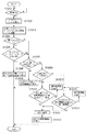
図10は、複写機1001におけるアプリケーションプログラムがワークフローを実行する処理を示すフローチャートである。図10の各ステップの処理は、複写機1001によって実行される。まず、ステップS1001では、操作モジュール801がユーザによってワークフローの実行を指示されたか否かを判定する。その結果、ワークフローの実行を指示された場合は、ワークフローの実行を制御モジュール802に指示し、ステップS1002へ処理を移行する。
FIG. 10 is a flowchart showing processing in which the application program in the copying machine 1001 executes a workflow. Processing of each step in FIG. 10 is executed by the copying machine 1001. First, in step S1001, it is determined whether the
ステップS1002では、制御モジュール802が、ユーザが指示したワークフローの入力工程を実行する。このとき、制御モジュール802は、入力工程の処理に応じて印刷データの名称と印刷データのハッシュデータを一時記憶領域804に保存し、ステップS1003へ処理を移行する。具体的には、ワークフローの入力がジョブ受信であれば、図13の操作画面を介して選択されたデータのハッシュデータを求め、印刷データの名称と共に一時記憶領域804に保存する。また、原稿読込であれば、読み込んだ原稿の画像データのハッシュデータを求め、その原稿の名称と共に一時記憶領域804に保存する。また、FAX受信、I−FAX受信であれば、受信したデータの名称とハッシュデータを一時記憶領域804に保存する。
In step S1002, the
ステップS1003では、制御モジュール802は、S1002の入力工程で入力された印刷データを特定すべく、一時記憶領域804に保存した印刷データの名称とハッシュデータをキーとしてボックス領域803の印刷データを検索する。そして、検索が終了すると、制御モジュール802はステップS1004において、ステップS1003で印刷データが見つかったか否かを判定する。その結果、印刷データが見つかった場合はステップS1005へ処理を移行するが、見つからなかった場合はステップS1007へ処理を移行する。つまり、制御モジュール802は、S1001にて実行指示されたワークフローにおいて利用可能な処理済みデータが画像形成装置の記憶部に保存されているか否かを判定する。
In step S1003, the
このステップS1005で、制御モジュール802はステップS1003で検索された印刷データがワークフローで利用可能か否かを印刷データ情報の設定情報904〜906に基づいて判定する。例えば、ボックス領域803に格納された印刷データの面付け情報904が4in1(複数の面付け)で、実行するワークフローに2in1の面付けの複写機機能が指定されている場合、更に面付けを行うことは困難であるため、利用不可と判定する。また、面付けの複写機機能が指定されている場合でも、ボックス領域803に格納された印刷データの面付け情報904が1in1であれば、利用可能と判定する。
In step S1005, the
尚、図10のフローチャートでは、S1004の判定処理において見つかったと判定された場合、S1005の処理を実行しているが、S1005の判定処理を実行しなくても良い。その場合、制御モジュール802は、S1004において見つかったデータを用いて、S1001において指定されたワークフローを実行する。
In the flowchart of FIG. 10, when it is determined in the determination process of S1004 that the process of S1005 is executed, the determination process of S1005 may not be executed. In that case, the
ステップS1005で、利用可能であると判定した場合はステップS1006へ処理を移行し、また利用不可と判断した場合はステップS1007へ処理を移行する。 If it is determined in step S1005 that the service can be used, the process proceeds to step S1006. If it is determined that the service cannot be used, the process proceeds to step S1007.
ステップS1006では、制御モジュール802はボックス領域803の印刷データを使ってワークフローを途中から最後まで実行する。即ち、ワークフローで指定されている編集(プレビューや文書結合、ページ削除)と出力(面付けや印刷、送信)を実行する。尚、この場合、ボックス領域803に保存するまでに実行したRIP処理などは行わず、保存されているデータを用いることで、処理効率を向上させる。また、制御モジュール802はS802において実効したワークフローによって生成された処理済みデータを保存することなく複数の処理について連続処理を実行する。
In step S1006, the
ステップS1007では、制御モジュール802は、実行指示されたワークフローに含まれる入力工程によって入力された入力データに従って当該ワークフローを実行することで得られた入力データに基づく処理済みデータを保存するか否かを判定する。具体的には、制御モジュール802が、S1001において実行指示されたワークフローの入力工程にて入力されたデータが印刷ジョブに基づく処理済みデータであるか、画像読み取り処理によって入力されたデータであるかを判定する。そして、制御モジュール802がワークフローの入力工程によって入力された入力データが情報処理装置から発行された印刷ジョブである場合、当該印刷ジョブに基づく処理済みデータを保存すると判定する(S1007−Yes)。
In step S1007, the
一方、制御モジュール802がワークフローの入力工程によって入力された入力データが画像読み取り処理によって入力されたデータである場合、当該入力データに基づく処理済みデータを保存しないと判定する(S1007でNo)。S1007においてYesと判定された場合、S1009の処理へと進み、S1007においてNoと判定された場合、S1008へと処理を進める。また、S1007の判定処理のその他の具体例として、入力データの発行元に基づいて判定しても良い。
On the other hand, if the input data input by the workflow input process is data input by the image reading process, the
この場合、制御モジュール802は、入力工程によって入力されたデータが所定の発行元から発行されたデータであるか否かを判定する。そして、所定の発行元から発行されたデータである場合、制御モジュールは、当該データに基づく処理済みデータを保存すると判定する(S1007でYes)。一方、所定の発行元から発行されたデータでない場合、制御モジュール802は、当該データに基づく処理済みデータを保存しないと判定する(S1007でNo)。尚、発行元ユーザを用いてS1007の判定処理を実行する場合、入力データに基づく処理済みデータを保存するための保存条件として、所定の発行元となる発行ユーザを設定する必要がある。
In this case, the
また、S1007の判定処理の更なる具体例として、入力工程の処理内容が印刷ジョブであり、かつ、ジョブの発行元が所定の発行元であると判定された場合、制御モジュール802は、S1007においてYesと判定しても良い。
As a further specific example of the determination process in S1007, when it is determined that the processing content of the input process is a print job and the job issuer is a predetermined issuer, the
ステップS1008では、制御モジュール802は、読み込んだ画像データや受信したFAXデータなどの入力印刷データを使ってワークフローの複写機機能を全て実行する。尚、ワークフローの入力が原稿読込やFAX受信の場合、入力を実行する毎に画像データが変化し、次のワークフロー実行時に流用が困難である。そのため、制御モジュール802は、S1008において、ワークフローを実行することで得られる処理済みデータを保存することなく複数の処理について連続処理を実行する
ステップS1009では、制御モジュール802は、編集の複写機機能に文書結合又はページ削除が含まれるかを判定する。ここで、文書結合又はページ削除が含まれる場合はステップS1010へ処理を移行し、また文書結合又はページ削除が含まれない場合にはステップS1014へ処理を移行する。
In step S1008, the
ステップS1010では、制御モジュール802は、実行中のワークフローにおいて、次に実行する複写機機能が文書結合又はページ削除であるかを判定する。その結果、文書結合又はページ削除でない場合はステップS1013へ処理を移行し、その複写機機能を実行し、処理内容を一時記憶領域804に保存してステップS1010に戻る。
In step S1010, the
このステップS1010で、次に実行する複写機機能が文書結合又はページ削除の場合はステップS1011へ処理を移行し、制御モジュール802は、印刷データをボックス領域803に保存する。これは、次回、ワークフローが実行された場合に、印刷データを再利用する。そのため、制御モジュール802は、S1011においてワークフローを実行することで得られる処理済みデータを画像形成装置の記憶部に保存する保存処理を含む複数の処理について連続処理を実行する。
If it is determined in step S1010 that the next copier function to be executed is document combination or page deletion, the process proceeds to step S1011 and the
このとき、出力の複写機機能に応じて印刷データの保存形式を決定する。例えば、出力が印刷の場合はJPEG形式で保存する。また、一時記憶領域804に記憶されている印刷データの名称、ハッシュデータ、及び処理内容を印刷データ情報としてボックス領域803に保存する。そして、ステップS1012へ処理を移行し、制御モジュール802は、このワークフローにおいて未実行の複写機機能を全て実行する。
At this time, the print data storage format is determined according to the output copier function. For example, if the output is printing, save it in JPEG format. In addition, the name, hash data, and processing content of the print data stored in the
ステップS1014では、制御モジュール802は、実行中のワークフローにおいて、次に実行する複写機機能が出力であるか否かを判定する。ここで、出力を実行する場合は上述のステップS1011へ処理を移行し、出力でない場合はステップS1015へ処理を移行する。
In step S1014, the
ステップS1015では、制御モジュール802は、指定されている複写機機能を実行し、ステップS1014へ処理を移行する。
In step S1015, the
尚、第1の実施形態では、利用可能な印刷データの検索を複写機1001で行っているが、印刷データの名称とハッシュデータを他の画像形成装置(例えば、複写機1002)に送信し、検索を行わせても良い。そして、利用可能な印刷データが保存されている複写機がその印刷データを用いてワークフローを実行するようにしても良い。 In the first embodiment, the search for available print data is performed by the copying machine 1001, but the print data name and hash data are transmitted to another image forming apparatus (for example, the copying machine 1002). A search may be performed. A copier in which usable print data is stored may execute a workflow using the print data.
また、図10のフローチャートでは、S1007の判定処理によってYesと判定された場合、S1009またはS1014の判定処理を行ってからS1011のBoxへの保存処理を行っている。しかしながら、これに限ることなく制御モジュールが以下のようにワークフローを実行しても良い。制御モジュール802は、S1007によって入力データに基づく処理済みデータを保存すると判定した場合、ワークフローを実行して得られる処理済みデータをBoxへ保存する処理を含む複数の処理について連続処理を実行する。一方、制御モジュールは、S1007によって入力データに基づく処理済みデータを保存しないと判定した場合、ワークフローを実行して得られる処理済みデータをBoxへ保存することなく複数の処理について連続処理を実行する。
In the flowchart of FIG. 10, when it is determined Yes in the determination process of S1007, the determination process of S1009 or S1014 is performed and then the storage process to the box of S1011 is performed. However, the present invention is not limited to this, and the control module may execute the workflow as follows. If the
第1の実施形態によれば、入力データに従って選択的に再利用可能な入力データに基づく処理済みデータが画像形成装置の記憶部に格納されるため、ユーザの無駄な処理を軽減することが可能となる。 According to the first embodiment, processed data based on input data that can be selectively reused according to the input data is stored in the storage unit of the image forming apparatus, so that it is possible to reduce unnecessary processing by the user. It becomes.
更に、第1の実施形態によれば、実行するワークフローを解析し、印刷データの最適な保存のタイミングと保存形式を判別し、印刷データを処理の途中で保存しておき、ワークフローを実行する際に保存された印刷データを使って途中から自動的に実行する。これにより、ユーザが保存データを管理するという負荷を軽減し、また、印刷に関わる処理を最初から全てやり直すといった無駄な処理を軽減することができる。 Furthermore, according to the first embodiment, when the workflow to be executed is analyzed, the optimum storage timing and storage format of the print data is determined, the print data is stored during the processing, and the workflow is executed. The print data saved in is automatically executed from the middle. As a result, it is possible to reduce the load of managing stored data by the user, and it is possible to reduce unnecessary processing such as redoing all processing related to printing from the beginning.
[第2の実施形態]
次に、図面を参照しながら本発明に係る第2の実施形態を詳細に説明する。第1の実施形態では、ワークフローの実行が開始されると、入力の複写機機能を実行して印刷データの名称やハッシュデータを解析している。しかし、印刷データの名称やハッシュデータを操作部からユーザに入力させる方法やクライアントコンピュータから受け取る方法を適用しても良い。
[Second Embodiment]
Next, a second embodiment according to the present invention will be described in detail with reference to the drawings. In the first embodiment, when execution of a workflow is started, the input copier function is executed to analyze the name of print data and hash data. However, a method of causing the user to input the name of print data and hash data from the operation unit or a method of receiving from the client computer may be applied.
図11は、印刷データの名称及びハッシュデータを入力するための画面の一例を示す図である。図11に示すように、ワークフローにおける入力の複写機機能を実行する前に、印刷データの名称やハッシュデータをユーザに入力させるか、FAX受信元やジョブ受信元から受け取ることで、入力処理を省くことができる。また、FAX受信やジョブ受信における印刷データの送受信によるネットワークトラフィックを軽減することができる。 FIG. 11 is a diagram illustrating an example of a screen for inputting the name of print data and hash data. As shown in FIG. 11, before executing the input copier function in the workflow, the input process is omitted by allowing the user to input the print data name or hash data, or by receiving it from a FAX reception source or job reception source. be able to. In addition, network traffic due to transmission / reception of print data in FAX reception or job reception can be reduced.
[第3の実施形態]
次に、図面を参照しながら本発明に係る第3の実施形態を詳細に説明する。第1の実施形態では、印刷データ及び印刷データ情報をボックス領域803に保存するタイミングは、制御モジュール802が自動的に決定している。しかし、ボックス領域803への保存のタイミングをユーザに指定させるようにしても良い。
[Third Embodiment]
Next, a third embodiment according to the present invention will be described in detail with reference to the drawings. In the first embodiment, the
図12は、ワークフローに複写機機能を登録/編集する画面でボックス領域803への保存のタイミングを指定させるための画面の一例を示す図である。図12に示すように、ユーザが保存の挿入ボタン1201を押下することにより、ワークフローのリスト705に保存1202が挿入される。
FIG. 12 is a view showing an example of a screen for designating the timing of storage in the
第3の実施形態によれば、ワークフローに複写機機能を登録/編集する画面でユーザがボックス領域803に保存するタイミングを指定することができる。
According to the third embodiment, the user can designate the timing for saving in the
尚、本発明は複数の機器(例えば、ホストコンピュータ,インターフェース機器,リーダ,プリンタなど)から構成されるシステムに適用しても、1つの機器からなる装置(例えば、複写機,ファクシミリ装置など)に適用しても良い。 Even if the present invention is applied to a system composed of a plurality of devices (for example, a host computer, an interface device, a reader, a printer, etc.), it is applied to an apparatus (for example, a copier, a facsimile machine, etc.) composed of a single device. It may be applied.
また、前述した実施形態の機能を実現するソフトウェアのプログラムコードを記録した記録媒体を、システム或いは装置に供給し、そのシステム或いは装置のコンピュータ(CPU若しくはMPU)が記録媒体に格納されたプログラムコードを読出し実行する。これによっても、本発明の目的が達成されることは言うまでもない。 In addition, a recording medium in which a program code of software for realizing the functions of the above-described embodiments is recorded is supplied to the system or apparatus, and the computer (CPU or MPU) of the system or apparatus stores the program code stored in the recording medium. Read and execute. It goes without saying that the object of the present invention can also be achieved by this.
この場合、記録媒体から読出されたプログラムコード自体が前述した実施形態の機能を実現することになり、そのプログラムコードを記憶した記録媒体は本発明を構成することになる。 In this case, the program code itself read from the recording medium realizes the functions of the above-described embodiment, and the recording medium storing the program code constitutes the present invention.
このプログラムコードを供給するための記録媒体として、例えばフレキシブルディスク,ハードディスク,光ディスク,光磁気ディスク,CD−ROM,CD−R,磁気テープ,不揮発性のメモリカード,ROMなどを用いることができる。 As a recording medium for supplying the program code, for example, a flexible disk, a hard disk, an optical disk, a magneto-optical disk, a CD-ROM, a CD-R, a magnetic tape, a nonvolatile memory card, a ROM, or the like can be used.
また、コンピュータが読出したプログラムコードを実行することにより、前述した実施形態の機能が実現されるだけでなく、次の場合も含まれることは言うまでもない。即ち、プログラムコードの指示に基づき、コンピュータ上で稼働しているOS(オペレーティングシステム)などが実際の処理の一部又は全部を行い、その処理により前述した実施形態の機能が実現される場合である。 In addition, by executing the program code read by the computer, not only the functions of the above-described embodiments are realized, but also the following cases are included. That is, based on the instruction of the program code, an OS (operating system) running on the computer performs part or all of the actual processing, and the functions of the above-described embodiments are realized by the processing. .
更に、記録媒体から読出されたプログラムコードがコンピュータに挿入された機能拡張ボードやコンピュータに接続された機能拡張ユニットに備わるメモリに書込む。その後、そのプログラムコードの指示に基づき、その機能拡張ボードや機能拡張ユニットに備わるCPUなどが実際の処理の一部又は全部を行い、その処理により前述した実施形態の機能が実現される場合も含まれることは言うまでもない。 Further, the program code read from the recording medium is written in a memory provided in a function expansion board inserted into the computer or a function expansion unit connected to the computer. After that, based on the instruction of the program code, the CPU of the function expansion board or function expansion unit performs part or all of the actual processing, and the function of the above-described embodiment is realized by the processing. Needless to say.
1001 複写機
1002 複写機
1001 copier 1002 copier
Claims (8)
前記ワークフローの実行を指示する指示手段と、
前記ワークフローに含まれる入力工程によって入力された入力データの発行元に従って、当該ワークフローによって生成された当該入力データに基づく処理済みデータを保存するか否かを判定する第1判定手段と、
前記第1判定手段によって保存すると判定された場合、前記ワークフローを実行することで得られる処理済みデータを記憶手段に保存する保存処理を含む複数の処理について連続処理を実行し、前記第1判定手段によって保存しないと判定した場合、前記ワークフローを実行することで得られる処理済みデータを保存することなく、複数の処理について連続処理を実行するワークフロー制御手段と、
を有することを特徴とする画像形成装置。 An image forming apparatus that performs the image formation according to a workflow that defines a plurality of processes that realize functions related to image formation as continuous processes,
Instruction means for instructing execution of the workflow;
First determination means for determining whether or not to store processed data based on the input data generated by the workflow according to an issuer of input data input by the input step included in the workflow;
When it is determined to be stored by the first determination unit, continuous processing is executed for a plurality of processes including a storage process for storing processed data obtained by executing the workflow in a storage unit, and the first determination unit If it is determined that the data is not saved by the workflow control means for executing continuous processing for a plurality of processes without saving processed data obtained by executing the workflow;
An image forming apparatus comprising:
前記ワークフロー制御手段は、前記第2判定手段によって当該ワークフローにおいて利用可能な処理済みデータが前記記憶手段に保存されていると判定された場合、前記ワークフローを実行することで得られる処理済みデータを保存することなく前記利用可能な処理済みデータを用いて複数の処理について連続処理を実行することを特徴とする請求項1に記載の画像形成装置。 A second determination unit that determines whether processed data usable in the workflow instructed to be executed by the instruction unit is stored in the storage unit;
The workflow control unit stores processed data obtained by executing the workflow when the second determining unit determines that processed data usable in the workflow is stored in the storage unit. The image forming apparatus according to claim 1, wherein a continuous process is executed for a plurality of processes using the available processed data without performing the process.
指示手段が、前記ワークフローの実行を指示する指示工程と、
第1判定手段が、前記ワークフローに含まれる入力工程によって入力された入力データの発行元に従って、当該ワークフローによって生成された当該入力データに基づく処理済みデータを保存するか否かを判定する第1判定工程と、
ワークフロー制御手段が、前記第1判定工程において保存すると判定された場合、前記ワークフローを実行することで得られる処理済みデータを記憶手段に保存する保存処理を含む複数の処理について連続処理を実行し、前記第1判定工程において保存しないと判定した場合、前記ワークフローを実行することで得られる処理済みデータを保存することなく、複数の処理について連続処理を実行するワークフロー制御工程と、
を有することを特徴とする画像形成装置の制御方法。 A control method of an image forming apparatus that performs the image formation according to a workflow that defines a plurality of processes that realize functions relating to image formation as continuous processes,
An instruction means for instructing execution of the workflow; and
First determination means for determining whether or not to store processed data based on the input data generated by the workflow according to an issuer of the input data input by the input step included in the workflow Process,
If the workflow control unit is determined to be stored at the first determination step, it executes a continuous process for a plurality of processes including a storage process for storing the processed data obtained by executing the workflow storage unit and, if it is determined not to store at the first determination step, without storing the processed data obtained by executing the workflow, a workflow control performing a continuous treatment for a plurality of processes,
A control method for an image forming apparatus, comprising:
Priority Applications (2)
| Application Number | Priority Date | Filing Date | Title |
|---|---|---|---|
| JP2006336382A JP4845700B2 (en) | 2006-12-13 | 2006-12-13 | Image forming apparatus and control method thereof |
| US11/950,412 US20080144092A1 (en) | 2006-12-13 | 2007-12-04 | Image forming apparatus and method of controlling same |
Applications Claiming Priority (1)
| Application Number | Priority Date | Filing Date | Title |
|---|---|---|---|
| JP2006336382A JP4845700B2 (en) | 2006-12-13 | 2006-12-13 | Image forming apparatus and control method thereof |
Publications (3)
| Publication Number | Publication Date |
|---|---|
| JP2008146606A JP2008146606A (en) | 2008-06-26 |
| JP2008146606A5 JP2008146606A5 (en) | 2010-02-04 |
| JP4845700B2 true JP4845700B2 (en) | 2011-12-28 |
Family
ID=39526795
Family Applications (1)
| Application Number | Title | Priority Date | Filing Date |
|---|---|---|---|
| JP2006336382A Expired - Fee Related JP4845700B2 (en) | 2006-12-13 | 2006-12-13 | Image forming apparatus and control method thereof |
Country Status (2)
| Country | Link |
|---|---|
| US (1) | US20080144092A1 (en) |
| JP (1) | JP4845700B2 (en) |
Families Citing this family (4)
| Publication number | Priority date | Publication date | Assignee | Title |
|---|---|---|---|---|
| JP5495629B2 (en) * | 2008-07-04 | 2014-05-21 | キヤノン株式会社 | Workflow control method, control device, and program |
| JP5471101B2 (en) * | 2009-07-15 | 2014-04-16 | 富士ゼロックス株式会社 | Information processing apparatus and program |
| KR20170024488A (en) | 2015-08-25 | 2017-03-07 | 에스프린팅솔루션 주식회사 | Method and image forming divice for generating workform of image forming job |
| JP2019009693A (en) | 2017-06-27 | 2019-01-17 | キヤノン株式会社 | Workflow generation device, workflow generation method, and program |
Family Cites Families (18)
| Publication number | Priority date | Publication date | Assignee | Title |
|---|---|---|---|---|
| JPH11249777A (en) * | 1998-02-27 | 1999-09-17 | Toshiba Corp | Document management system and its method |
| JPH11296665A (en) * | 1998-04-13 | 1999-10-29 | Minolta Co Ltd | Image processing method, its device and recording medium |
| US7151613B1 (en) * | 1999-02-18 | 2006-12-19 | Minolta Co., Ltd. | Printer |
| US7002700B1 (en) * | 2000-09-14 | 2006-02-21 | Electronics For Imaging, Inc. | Method and system for merging scan files into a color workflow |
| JP3854876B2 (en) * | 2001-03-08 | 2006-12-06 | キヤノン株式会社 | Information processing apparatus, printing control method therefor, and storage medium |
| JP2003163801A (en) * | 2001-11-26 | 2003-06-06 | Fuji Xerox Co Ltd | Apparatus, method, and program for image processing, and storage medium |
| US7408658B2 (en) * | 2001-12-04 | 2008-08-05 | Hewlett-Packard Development Company, L.P. | Generation and usage of workflows for processing data on a printing device |
| JP2003345954A (en) * | 2002-05-28 | 2003-12-05 | Murata Mach Ltd | Workflow management device |
| JP3774702B2 (en) * | 2003-02-12 | 2006-05-17 | キヤノン株式会社 | Print control program and information processing apparatus |
| EP1452956A3 (en) * | 2003-02-12 | 2010-03-17 | Canon Kabushiki Kaisha | print control system |
| US20070276823A1 (en) * | 2003-05-22 | 2007-11-29 | Bruce Borden | Data management systems and methods for distributed data storage and management using content signatures |
| EP1641237A3 (en) * | 2004-09-22 | 2006-07-26 | Sharp Kabushiki Kaisha | Image processing apparatus and image processing system |
| KR100636181B1 (en) * | 2004-10-01 | 2006-10-19 | 삼성전자주식회사 | Method and apparatus for inserting scanning document |
| US20060139671A1 (en) * | 2004-12-27 | 2006-06-29 | Kabushiki Kaisha Toshiba | Image forming apparatus and method of controlling apparatus |
| JP4429186B2 (en) * | 2005-02-10 | 2010-03-10 | 京セラミタ株式会社 | Image forming apparatus |
| JP4630751B2 (en) * | 2005-07-28 | 2011-02-09 | キヤノン株式会社 | Printing system, printing apparatus, control method therefor, and program |
| US20070030510A1 (en) * | 2005-08-08 | 2007-02-08 | Yoshimine Horiuchi | Image processing apparatus, image output method, and computer program product |
| JP4763440B2 (en) * | 2005-12-02 | 2011-08-31 | 株式会社リコー | Image forming apparatus, image forming method, and image forming program |
-
2006
- 2006-12-13 JP JP2006336382A patent/JP4845700B2/en not_active Expired - Fee Related
-
2007
- 2007-12-04 US US11/950,412 patent/US20080144092A1/en not_active Abandoned
Also Published As
| Publication number | Publication date |
|---|---|
| JP2008146606A (en) | 2008-06-26 |
| US20080144092A1 (en) | 2008-06-19 |
Similar Documents
| Publication | Publication Date | Title |
|---|---|---|
| JP4510543B2 (en) | Image processing apparatus, printing apparatus, and image processing method | |
| JP5602909B2 (en) | Image processing apparatus, processing flow execution method of image processing apparatus, and program | |
| JP4510652B2 (en) | Image processing apparatus, information processing method, program, and storage medium | |
| JP2011166748A (en) | Image processor, control method thereof, and program | |
| JP4928373B2 (en) | Image processing apparatus, image processing method, and image processing program | |
| US8730493B2 (en) | Image processing apparatus, method of controlling the same, and storage medium | |
| JP4908773B2 (en) | Image processing apparatus, control method therefor, program, and storage medium | |
| JP2011119941A (en) | Image forming apparatus, and method for controlling the same | |
| JP4748785B2 (en) | Information processing apparatus, data processing method, storage medium, and computer program | |
| JP4845700B2 (en) | Image forming apparatus and control method thereof | |
| JP2004004622A (en) | Image forming apparatus and form setting control method | |
| JP2007310468A (en) | Image forming apparatus | |
| JP2007122279A (en) | Image processor, image processing method, and program | |
| JP2000137798A (en) | Device and method for image input and output, and image processing system | |
| JP3870200B2 (en) | Job management apparatus, management method, and computer-readable storage medium | |
| JP2006019904A (en) | Image processor and processing method, storage medium storing computer readable program, and program | |
| JP4185744B2 (en) | Image processing apparatus, document management system, image processing apparatus control method, and control program | |
| JP2007118239A (en) | Image processor system | |
| JP2006205442A (en) | Image forming apparatus, information processing method, program, and memory medium | |
| JP4612775B2 (en) | Image forming apparatus and control method thereof | |
| JP2003011443A (en) | Imaging apparatus, printing control method, program and storage medium | |
| JP2004102377A (en) | Image processor, its control method and its control program | |
| JP2008269234A (en) | Image forming apparatus, control method, program and storage medium | |
| JP2005078490A (en) | Image processing device | |
| JP2007114298A (en) | Image processor |
Legal Events
| Date | Code | Title | Description |
|---|---|---|---|
| A521 | Written amendment |
Free format text: JAPANESE INTERMEDIATE CODE: A523 Effective date: 20091211 |
|
| A621 | Written request for application examination |
Free format text: JAPANESE INTERMEDIATE CODE: A621 Effective date: 20091211 |
|
| A977 | Report on retrieval |
Free format text: JAPANESE INTERMEDIATE CODE: A971007 Effective date: 20110926 |
|
| TRDD | Decision of grant or rejection written | ||
| A01 | Written decision to grant a patent or to grant a registration (utility model) |
Free format text: JAPANESE INTERMEDIATE CODE: A01 Effective date: 20111003 |
|
| A01 | Written decision to grant a patent or to grant a registration (utility model) |
Free format text: JAPANESE INTERMEDIATE CODE: A01 |
|
| A61 | First payment of annual fees (during grant procedure) |
Free format text: JAPANESE INTERMEDIATE CODE: A61 Effective date: 20111011 |
|
| FPAY | Renewal fee payment (event date is renewal date of database) |
Free format text: PAYMENT UNTIL: 20141021 Year of fee payment: 3 |
|
| FPAY | Renewal fee payment (event date is renewal date of database) |
Free format text: PAYMENT UNTIL: 20141021 Year of fee payment: 3 |
|
| LAPS | Cancellation because of no payment of annual fees |