JP4845552B2 - Isolated operation detection system for distributed power supply system and distributed power supply - Google Patents
Isolated operation detection system for distributed power supply system and distributed power supply Download PDFInfo
- Publication number
- JP4845552B2 JP4845552B2 JP2006083802A JP2006083802A JP4845552B2 JP 4845552 B2 JP4845552 B2 JP 4845552B2 JP 2006083802 A JP2006083802 A JP 2006083802A JP 2006083802 A JP2006083802 A JP 2006083802A JP 4845552 B2 JP4845552 B2 JP 4845552B2
- Authority
- JP
- Japan
- Prior art keywords
- power
- power failure
- distribution system
- failure information
- information
- Prior art date
- Legal status (The legal status is an assumption and is not a legal conclusion. Google has not performed a legal analysis and makes no representation as to the accuracy of the status listed.)
- Expired - Fee Related
Links
- 238000001514 detection method Methods 0.000 title claims description 87
- 238000004891 communication Methods 0.000 claims description 23
- 238000010248 power generation Methods 0.000 description 45
- 230000006870 function Effects 0.000 description 19
- 230000005540 biological transmission Effects 0.000 description 9
- 238000000034 method Methods 0.000 description 7
- 230000008569 process Effects 0.000 description 7
- 238000009434 installation Methods 0.000 description 5
- 238000010586 diagram Methods 0.000 description 4
- 230000008859 change Effects 0.000 description 3
- 239000002028 Biomass Substances 0.000 description 1
- 230000000903 blocking effect Effects 0.000 description 1
- 230000000694 effects Effects 0.000 description 1
- 230000007246 mechanism Effects 0.000 description 1
- 238000012986 modification Methods 0.000 description 1
- 230000004048 modification Effects 0.000 description 1
- 238000011084 recovery Methods 0.000 description 1
- 230000004044 response Effects 0.000 description 1
Images


Classifications
-
- Y—GENERAL TAGGING OF NEW TECHNOLOGICAL DEVELOPMENTS; GENERAL TAGGING OF CROSS-SECTIONAL TECHNOLOGIES SPANNING OVER SEVERAL SECTIONS OF THE IPC; TECHNICAL SUBJECTS COVERED BY FORMER USPC CROSS-REFERENCE ART COLLECTIONS [XRACs] AND DIGESTS
- Y02—TECHNOLOGIES OR APPLICATIONS FOR MITIGATION OR ADAPTATION AGAINST CLIMATE CHANGE
- Y02E—REDUCTION OF GREENHOUSE GAS [GHG] EMISSIONS, RELATED TO ENERGY GENERATION, TRANSMISSION OR DISTRIBUTION
- Y02E10/00—Energy generation through renewable energy sources
- Y02E10/70—Wind energy
- Y02E10/76—Power conversion electric or electronic aspects
Landscapes
- Supply And Distribution Of Alternating Current (AREA)
Description
本発明は、分散型電源の単独運転検出システムに関し、特に、配電系統に連系された分散型電源の単独運転を検出する分散型電源の単独運転検出システムに関する。 The present invention relates to an isolated operation detection system for a distributed power source, and more particularly to an isolated operation detection system for a distributed power source that detects an isolated operation of a distributed power source connected to a power distribution system.
近年、太陽光および風力などによる分散型電源を商用電力系統(配電系統)に連系させるとともに、その商用電力系統に連系された分散型電源の発電電力を逆潮流させることにより、電力会社に分散型電源の発電電力を売却することが可能な系統連系型分散電源が普及しつつある。そして、このような系統連系型分散電源では、商用電力系統の停電時に回復作業の安全を保つために、系統連系型分散電源を商用電力系統から分離する必要がある。すなわち、系統連系型分散電源の単独運転を防止する必要がある。 In recent years, distributed power sources such as solar and wind power have been linked to the commercial power system (distribution system), and the power generated by the distributed power source linked to the commercial power system has been reversed, allowing power companies to Grid-connected distributed power sources that can sell the power generated by distributed power sources are becoming widespread. In such a grid-connected distributed power supply, it is necessary to separate the grid-connected distributed power supply from the commercial power system in order to keep the recovery work safe in the event of a power failure in the commercial power system. That is, it is necessary to prevent the independent operation of the grid-connected distributed power source.
そこで、従来では、系統連系型分散電源の単独運転を検出する装置として、種々の単独運転検出装置が提案されている(たとえば、特許文献1参照)。 Therefore, conventionally, various isolated operation detection devices have been proposed as devices for detecting isolated operation of a grid-connected distributed power supply (see, for example, Patent Document 1).
上記特許文献1には、出力電力を一定の周期で変化させるとともに、この出力電力の変化を検出することにより、商用電力系統の停電を検出することが可能な分散型電源の単独運転検出装置が開示されている。なお、商用電力系統が正常なときには、出力電力の変化が商用電力系統により吸収されるので、出力電力の変化は検出されない。 Patent Document 1 discloses an isolated operation detection device for a distributed power source capable of detecting a power failure in a commercial power system by changing the output power at a constant cycle and detecting the change in the output power. It is disclosed. When the commercial power system is normal, the change in output power is absorbed by the commercial power system, so that the change in output power is not detected.
しかしながら、上記特許文献1に開示された分散型電源の単独運転検出装置では、分散型電源に回転機負荷などの変動する負荷が接続されている場合には、負荷消費電力が変化して、出力電力の変化を打ち消す場合があるため、出力電力の変化を検出することが困難になる場合がある。この場合には、商用電力系統(配電系統)の停電を検出することが困難になるので、上記特許文献1では、分散型電源の単独運転を確実に防止するのが困難であるという問題点がある。 However, in the distributed power supply isolated operation detection device disclosed in Patent Document 1, when a variable load such as a rotating machine load is connected to the distributed power supply, the load power consumption changes and the output Since changes in power may be canceled out, it may be difficult to detect changes in output power. In this case, since it is difficult to detect a power failure in the commercial power system (distribution system), the above-described Patent Document 1 has a problem that it is difficult to reliably prevent the independent operation of the distributed power source. is there.
この発明は、上記のような課題を解決するためになされたものであり、この発明の1つの目的は、配電系統の停電を確実に検出することができるとともに、分散型電源の単独運転を確実に防止することが可能な分散型電源の単独運転検出システムを提供することである。 The present invention has been made to solve the above-described problems, and one object of the present invention is to reliably detect a power failure in the distribution system and to ensure the independent operation of the distributed power source. It is an object of the present invention to provide an isolated operation detection system for a distributed power source that can be prevented.
上記目的を達成するために、この発明の第1の局面における分散型電源の単独運転検出システムは、配電系統に連系された分散型電源の単独運転を検出する分散型電源の単独運転検出システムであって、通信機能を有するとともに、配電系統が停電しているか否かの情報を保持し、かつ、情報を通信ネットワークを介して公開する第1停電情報公開装置と、通信機能を有するとともに、第1停電情報公開装置が保持する情報を通信ネットワークを介して取得し、かつ、第1停電情報公開装置から取得した情報に基づいて配電系統が停電していると判断した場合に、分散型電源を配電系統から分離する停電情報検知装置とを備える。 In order to achieve the above object, a distributed power supply isolated operation detection system according to a first aspect of the present invention is a distributed power supply isolated operation detection system for detecting isolated operation of a distributed power supply connected to a distribution system. In addition to having a communication function, holding information on whether or not the power distribution system has a power failure, and having a communication function, and a first power failure information disclosure device that discloses information via a communication network, When the information held by the first power outage information disclosure device is acquired via the communication network and it is determined that the power distribution system is out of power based on the information acquired from the first power outage information disclosure device, the distributed power source And a power failure information detection device for separating the power from the power distribution system.
この第1の局面による分散型電源の単独運転検出システムでは、上記のように、配電系統が停電しているか否かの情報を保持するとともに、情報を通信ネットワークを介して公開する第1停電情報公開装置と、第1停電情報公開装置が保持する情報を通信ネットワークを介して取得する停電情報検知装置とを設けることによって、停電情報検知装置により、通信ネットワーク経由で第1停電情報公開装置の情報が取得されるので、分散型電源に回転機負荷などの変動する負荷が接続されている場合にも、配電系統の停電を確実に検出することができる。また、停電情報検知装置を、第1停電情報公開装置から取得した情報に基づいて配電系統が停電していると判断した場合に、分散型電源を配電系統から分離するように構成することによって、分散型電源の単独運転を確実に防止することができる。また、停電情報検知装置を、第1停電情報公開装置が保持する配電系統が停電しているか否かの情報を通信ネットワークを介して取得するように構成することによって、配電用変電所が各分散型電源に停電信号を送信して各分散型電源を集中管理する場合と異なり、配電用変電所側が各分散型電源を管理する必要がないので、容易に、配電系統に多くの分散型電源を連系させるとができる。 In the isolated operation detection system of the distributed power source according to the first aspect, as described above, the first power failure information that holds information on whether or not the power distribution system has a power failure and discloses the information via a communication network is provided. Information of the first power failure information disclosure device via the communication network is provided by the power failure information detection device by providing the disclosure device and the power failure information detection device that acquires the information held by the first power failure information disclosure device via the communication network. Therefore, even when a variable load such as a rotating machine load is connected to the distributed power source, it is possible to reliably detect a power failure in the distribution system. Moreover, by configuring the power failure information detection device to separate the distributed power source from the power distribution system when it is determined that the power distribution system has a power failure based on the information acquired from the first power failure information disclosure device, The isolated operation of the distributed power source can be reliably prevented. In addition, by configuring the power outage information detection device so as to obtain information on whether or not the power distribution system held by the first power outage information disclosure device has a power outage, the distribution substations are each distributed. Unlike the case where a power failure signal is sent to a distributed power source and each distributed power source is centrally managed, there is no need for the distribution substation to manage each distributed power source, so many distributed power sources can be easily added to the distribution system. It can be connected.
上記構成において、好ましくは、第1停電情報公開装置は、配電系統側に配置され、停電情報検知装置は、分散型電源側に配置されている。 In the above configuration, preferably, the first power failure information disclosure device is disposed on the distribution system side, and the power failure information detection device is disposed on the distributed power source side.
上記構成において、好ましくは、配電系統よりも高圧側に配置され、配電系統よりも高圧側が停電している場合にオフ状態になる1次側遮断機と、配電系統に接続され、配電系統が停電している場合にオフ状態になる2次側遮断機と、1次側遮断機の状態の情報を保持するとともに、情報を通信ネットワークを介して公開する第2停電情報公開装置とをさらに備え、第1停電情報公開装置は、第2停電情報公開装置が保持する情報を通信ネットワークを介して取得するとともに、第2停電情報公開装置から取得した情報に基づいて1次側遮断機がオフ状態であると判断した場合に、第1停電情報公開装置が保持する情報を配電系統が停電しているという情報に更新する。 In the above configuration, the primary circuit breaker which is preferably arranged on the high voltage side of the distribution system and is turned off when the high voltage side of the distribution system is out of power, and the distribution system is connected to the power distribution system. A secondary circuit breaker that is turned off when it is in operation, and a second power failure information disclosing device that retains information on the state of the primary circuit breaker and publishes the information through the communication network, The first power failure information disclosure device acquires information held by the second power failure information disclosure device via the communication network, and the primary circuit breaker is in an off state based on the information acquired from the second power failure information disclosure device. When it is determined that there is, the information held by the first power failure information disclosure device is updated to information that the power distribution system has a power failure.
この場合、好ましくは、第1停電情報公開装置は、第2停電情報公開装置から取得した情報に基づいて1次側遮断機がオン状態であると判断し、かつ、2次側遮断機がオン状態であると判断した場合に、第1停電情報公開装置が保持する情報を配電系統が停電していないという情報に更新する。 In this case, preferably, the first power failure information disclosure device determines that the primary circuit breaker is on based on the information acquired from the second power failure information disclosure device, and the secondary power breaker is on. When it is determined that the state is the state, the information held by the first power failure information disclosure device is updated to information that the power distribution system has not failed.
上記第2停電情報公開装置を備えた構成において、好ましくは、第1停電情報公開装置は、第2停電情報公開装置が保持する情報の取得を所定の時間間隔毎に行う。 In the configuration including the second power failure information disclosure device, preferably, the first power failure information disclosure device performs acquisition of information held by the second power failure information disclosure device at predetermined time intervals.
上記構成において、好ましくは、停電情報検知装置は、第1停電情報公開装置が保持する情報の取得に失敗した場合にも、分散型電源を配電系統から分離する。 In the above configuration, preferably, the power failure information detection device separates the distributed power source from the distribution system even when acquisition of information held by the first power failure information disclosure device fails.
上記構成において、好ましくは、停電情報検知装置は、分散型電源を配電系統から分離した後、第1停電情報公開装置から取得した情報に基づいて配電系統が停電していないと判断した場合には、分散型電源を配電系統に連系する。 In the above configuration, preferably, when the power failure information detection device determines that the power distribution system is not out of power based on the information acquired from the first power failure information disclosure device after separating the distributed power source from the power distribution system. Connect the distributed power supply to the power distribution system.
上記構成において、好ましくは、停電情報検知装置は、第1停電情報公開装置が保持する情報の取得を所定の時間間隔毎に行う。 In the above configuration, preferably, the power failure information detection device acquires information held by the first power failure information disclosure device at predetermined time intervals.
この発明の第2の局面における分散型電源の単独運転検出システムは、通信機能を有するとともに、停電しているか否かの情報を保持し、かつ、情報を通信ネットワークを介して公開する第1停電情報公開装置を備える配電系統に連系された分散型電源の単独運転を検出する分散型電源の単独運転検出システムであって、通信機能を有するとともに、第1停電情報公開装置が保持する情報を通信ネットワークを介して取得し、かつ、第1停電情報公開装置から取得した情報に基づいて配電系統が停電していると判断した場合に、分散型電源を配電系統から分離する停電情報検知装置を備える、分散型電源の単独運転検出システム。 A distributed power supply isolated operation detection system according to a second aspect of the present invention has a communication function, retains information on whether or not a power failure has occurred, and releases the information via a communication network. An isolated operation detection system for a distributed power source that detects an isolated operation of a distributed power source that is connected to a power distribution system that includes an information disclosure device. The distributed operation includes a communication function and information held by the first power failure information disclosure device. A power failure information detection device that separates a distributed power source from a power distribution system when it is determined that the power distribution system is out of power based on information acquired from a communication network and acquired from the first power failure information disclosure device. A distributed power supply isolated operation detection system.
以下、本発明の実施形態を図面に基づいて説明する。 Hereinafter, embodiments of the present invention will be described with reference to the drawings.
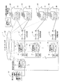
図1は、本発明の一実施形態による太陽光発電装置の単独運転検出システムの全体構成を説明するための概念図である。図2は、図1に示した一実施形態による太陽光発電装置の単独運転検出システムの全体構成を説明するためのブロック図である。まず、図1および図2を参照して、本実施形態による太陽光発電装置21の単独運転検出システム1の構成について説明する。なお、本実施形態では、分散型電源の一例である太陽光発電装置21に本発明を適用した場合について説明する。
FIG. 1 is a conceptual diagram for explaining the overall configuration of a stand-alone detection system for a photovoltaic power generator according to an embodiment of the present invention. FIG. 2 is a block diagram for explaining the overall configuration of the isolated operation detection system for the photovoltaic power generator according to the embodiment shown in FIG. 1. First, with reference to FIG. 1 and FIG. 2, the structure of the independent operation detection system 1 of the solar
本実施形態による太陽光発電装置21の単独運転検出システム1では、図1および図2に示すように、配電用変電所10と、太陽光発電装置21を含む太陽光発電装置設置住宅20と、配電用変電所10に電力を供給する高圧送電線50と、配電用変電所10から太陽光発電装置設置住宅20に電力を供給する配電系統51とを備えている。
In the independent operation detection system 1 of the solar
ここで、本実施形態では、配電用変電所10は、高圧送電線50から供給された電力の電圧を所定の電圧に下げるとともに、電力を複数の配電系統51に供給するために設けられている。この配電用変電所10は、給配電制御部11と、1次側遮断機12と、2次側遮断機13と、変圧器14と、停電情報公開サーバ15および16とを含んでいる。なお、停電情報公開サーバ15および16は、ぞれぞれ、本発明の「第2停電情報公開装置」および「第1停電情報公開装置」の一例である。給配電制御部11は、1次側遮断機12および2次側遮断機13をオン状態にして給電を開始させるために設けられている。また、1次側遮断機12は、高圧側の高圧送電線50側に配置されるとともに、高圧送電線50側において停電が発生したときにオフ状態になる機能を有している。また、複数の2次側遮断機13は、低圧側の配電系統51側に配置されるとともに、配電系統51において停電が発生したときにオフ状態になる機能を有している。また、複数の変圧器14は、高圧側の高圧送電線50から供給される電力の電圧を所定の電圧に下げて配電系統51に供給する機能を有している。また、2次側遮断機13および変圧器14は、複数の配電系統51の各々に対して1つずつ設けられている。
Here, in this embodiment, the
また、本実施形態では、1次側の停電情報公開サーバ15は、1次側遮断機12の状態の情報をインターネット網52を介して公開するために設けられている。この停電情報公開サーバ15は、制御部15aと、モデム15bと、メモリ15cと、リレー動作検知アダプタ15dとを含んでいる。なお、インターネット網52は、本発明の「通信ネットワーク」の一例である。
In the present embodiment, the primary-side power failure
また、本実施形態では、1次側の停電情報公開サーバ15の制御部15aは、停電情報公開サーバ15の動作を制御するために設けられている。この停電情報公開サーバ15の制御部15aは、リレー動作検知アダプタ15dに1次側遮断機12の状態を確認させるとともに、1次側遮断機12の状態をメモリ15cに格納する機能を有している。また、1次側の停電情報公開サーバ15の制御部15aは、インターネット網52を介して2次側停電情報公開サーバ16から1次側遮断機12の状態について問い合わせがあった場合に、メモリ15cに格納された情報を提供する機能も有している。
In the present embodiment, the
また、1次側の停電情報公開サーバ15のモデム15bは、停電情報公開サーバ15をインターネット網52に接続するために設けられている。メモリ15cには、インターネット網52内での停電情報公開サーバ15の識別番号である固定IPアドレスが記憶されている。また、メモリ15cは、1次側遮断機12の状態を格納する機能を有している。リレー動作検知アダプタ15dは、1次側遮断機12の状態を確認するために設けられている。
The modem 15 b of the primary-side power failure
また、本実施形態では、2次側の複数の停電情報公開サーバ16は、配電系統51が停電であるか否かの情報をインターネット網52を介して公開するために設けられている。この停電情報公開サーバ16は、制御部16aと、モデム16bと、メモリ16cと、リレー動作検知アダプタ16dとを含んでいる。また、停電情報公開サーバ16は、複数の配電系統51の各々に対応して1つずつ設けられている。
In the present embodiment, the plurality of secondary-side power failure
また、本実施形態では、2次側の停電情報公開サーバ16の制御部16aは、停電情報公開サーバ16の動作を制御するために設けられている。この停電情報公開サーバ16の制御部16aは、リレー動作検知アダプタ16dに2次側遮断機13の状態を確認させるとともに、インターネット網52を介して1次側の停電情報公開サーバ15に約1msec〜約1分の時間間隔でアクセスして、1次側遮断機12の状態を確認する機能を有している。また、制御部16aは、インターネット網52を介して1次側の停電情報公開サーバ15にアクセスできない場合には、1次側遮断機12がオフ状態であると判断する機能も有している。また、制御部16aは、1次側遮断機12および2次側遮断機13のうちの少なくとも一方がオフ状態の場合には、配電系統51が停電しているという情報をメモリ16cに格納するとともに、1次側遮断機12および2次側遮断機13の両方がオン状態の場合には、配電系統51が停電していないという情報をメモリ16cに格納する機能も有している。また、停電情報公開サーバ16の制御部16aは、インターネット網52を介して後述する停電情報検知クライアント23から配電系統51が停電しているか否かの問い合わせがあった場合に、メモリ16cに格納された情報を提供する機能も有している。
In the present embodiment, the
また、停電情報公開サーバ16のモデム16bは、停電情報公開サーバ16をインターネット網52に接続するために設けられている。メモリ16cには、インターネット網52内での停電情報公開サーバ16の識別番号である固定IPアドレスが記憶されている。また、メモリ16cには、インターネット網52を介して停電情報公開サーバ15にアクセスために停電情報公開サーバ15の固定IPアドレスも記憶されている。また、メモリ16cは、配電系統51が停電しているか否かの情報を格納する機能も有している。リレー動作検知アダプタ16dは、2次側遮断機13の状態を確認するために設けられている。
The
また、本実施形態では、各配電系統51には、複数の太陽光発電装置設置住宅20が連系(接続)されている。
In the present embodiment, each
また、本実施形態では、太陽光発電装置設置住宅20は、配電系統51に連系(接続)されるとともに、太陽光発電装置21の発電電力を逆潮流させることが可能なように構成されている。この太陽光発電装置設置住宅20は、太陽光により発電する太陽光発電装置21と、太陽光発電装置21と配電系統51との連系(接続)を制御するためのパワーコンディショナ22とを含んでいる。
Moreover, in this embodiment, the solar power generation
また、本実施形態では、パワーコンディショナ22は、停電情報検知クライアント23と、転送遮断ブレーカ24と、インバータ25とを含んでいる。停電情報検知クライアント23は、配電線系統51が停電している場合に、配電系統51から太陽光発電装置21を分離するために設けられている。この停電情報検知クライアント23は、制御部23aと、モデム23bと、メモリ23cと、リレー動作制御アダプタ23dとを含んでいる。なお、停電情報検知クライアント23は、本発明の「停電情報検知装置」の一例である。
In this embodiment, the
また、本実施形態では、停電情報検知クライアント23の制御部23aは、停電情報検知クライアント23の動作を制御するために設けられている。具体的には、制御部23aは、インターネット網52を介して連系(接続)する配電系統51の停電情報公開サーバ16に約1分〜約10分の時間間隔でアクセスして、配電系統51が停電しているか否かの情報を取得する機能を有している。また、制御部23aは、停電情報公開サーバ16から取得した情報に基づいて配電系統51が停電していると判断した場合には、リレー動作制御アダプタ23dにより転送遮断ブレーカ24をオフ状態にする機能も有している。また、制御部23aは、転送遮断ブレーカ24をオフ状態にした後に、停電情報公開サーバ16から取得した情報に基づいて配電系統51が停電していないと判断した場合には、停電から復旧したと判断して、リレー動作制御アダプタ23dにより転送遮断ブレーカ24をオン状態にする機能も有している。また、制御部23aは、インターネット網52を介して停電情報公開サーバ16にアクセスできない場合には、リレー動作制御アダプタ23dにより転送遮断ブレーカ24をオフ状態にする機能も有している。また、制御部23aは、太陽光発電装置21を起動および停止させる機能も有している。
In the present embodiment, the
また、停電情報検知クライアント23のモデム23bは、停電情報検知クライアント23をインターネット網52に接続するために設けられている。メモリ23cには、インターネット網52内での停電情報検知クライアント23の識別番号である動的IPアドレスが記憶されている。また、メモリ23cには、インターネット網52を介して連系(接続)する配電系統51の停電情報公開サーバ16にアクセスために停電情報公開サーバ16の固定IPアドレスも記憶されている。リレー動作制御アダプタ23dは、転送遮断ブレーカ24の状態を切り替えるために設けられている。
The
また、転送遮断ブレーカ24は、オン状態およびオフ状態を切り替えることにより、太陽光発電装置21を配電系統51に連系(接続)するとともに、配電系統51から分離するために設けられている。インバータ25は、太陽光発電装置21から逆潮流させる電流を、直流から配電系統51と同じ周波数の交流電流へと変換するために設けられている。
In addition, the
図3は、図1に示した一実施形態による太陽光発電装置の単独運転検出システムの2次側の停電情報公開サーバの動作を説明するためのフローチャートである。図2および図3を参照して、本実施形態による太陽光発電装置21の単独運転検出システム1の停電情報公開サーバ16の動作について説明する。
FIG. 3 is a flowchart for explaining the operation of the secondary-side power failure information disclosure server of the solar power generation device single operation detection system according to the embodiment shown in FIG. 1. With reference to FIG. 2 and FIG. 3, the operation | movement of the power failure
まず、図3のステップS1において、給配電制御部11により、1次側遮断機12および2次側遮断機13がオン状態にされる。これにより、給電が開始される。
First, in step S1 of FIG. 3, the power distribution control unit 11 turns on the
次に、ステップS2において、2次側の停電情報公開サーバ16の制御部16aにより、リレー動作検知アダプタ16dを介して2次側遮断機13がオン状態か否かが判断される。そして、制御部16aにより、2次側遮断機13がオフ状態であると判断された場合には、ステップS6に移行する。その一方、制御部16aにより、2次側遮断機13がオン状態であると判断された場合には、ステップS3に移行する。
Next, in step S2, the
そして、ステップS3において、2次側の停電情報公開サーバ16の制御部16aにより、1次側の停電情報公開サーバ15にアクセスする。このとき、停電情報公開サーバ15のメモリ15cに格納された1次側遮断機12の状態を取得する。次に、ステップS4において、2次側の停電情報公開サーバ16の制御部16aにより、1次側遮断機12がオン状態か否かが判断される。そして、制御部16aにより、1次側遮断機12がオフ状態であると判断された場合には、ステップS6に移行する。その一方、制御部16aにより、1次側遮断機12がオン状態であると判断された場合には、ステップS5に移行する。
In step S3, the
そして、ステップS5において、制御部16aにより、配電系統51が停電でないという情報をメモリ16cに格納してステップS7に移行する。
In step S5, the
また、ステップS6において、制御部16aにより、配電系統51が停電であるという情報をメモリ16cに格納してステップS7に移行する。
Moreover, in step S6, the
次に、ステップS7において、制御部16aにより、メモリ16cに格納されている配電系統51が停電しているか否かの情報をインターネット網52を介して公開する。このとき、2次側の停電情報公開サーバ16の制御部16aは、停電情報検知クライアント23から配電系統51が停電しているか否かの問い合わせに対して、メモリ16cに格納された情報を提供する。
Next, in step S <b> 7, the
次に、ステップS8において、制御部16aにより、約1msec〜約1分間だけ待機する。その後、ステップS2に戻る。
Next, in step S8, the
図4は、図1に示した一実施形態による太陽光発電装置の単独運転検出システムの停電情報検知クライアントの動作を説明するためのフローチャートである。図2および図4を参照して、本実施形態による太陽光発電装置21の単独運転検出システム1の停電情報検知クライアント23の動作について説明する。
FIG. 4 is a flowchart for explaining the operation of the power failure information detection client of the isolated operation detection system for the photovoltaic power generator according to the embodiment shown in FIG. With reference to FIG. 2 and FIG. 4, the operation | movement of the power failure
まず、ステップS9において、停電情報検知クライアント23の制御部23aにより、太陽光発電装置21を起動させる。次に、ステップS10において、制御部23aにより、連系する配電系統51の停電情報公開サーバ16にアクセスする。このとき、停電情報公開サーバ16のメモリ16cに格納された配電系統51が停電しているか否かの情報を取得する。
First, in step S <b> 9, the solar
次に、ステップS11において、制御部23aにより、配電系統51が停電しているか否かが判断される。そして、制御部23aにより、配電系統51が停電していると判断された場合には、ステップS13に移行する。ステップS13では、制御部23aにより、リレー動作制御アダプタ23dに転送遮断ブレーカ24をオフ状態にさせるとともに、太陽光発電装置21を停止させる。これにより、太陽光発電装置21が配電系統51から分離される。その一方、配電系統51が停電していないと判断された場合には、ステップS12に進み、約1分〜約10分間だけ待機した後、ステップS10に戻る。
Next, in step S11, the
ステップS13の処理の後、ステップS14において、制御部23aにより、約1分〜約10分間だけ待機する。
After the process of step S13, in step S14, the
その後、ステップS15において、制御部23aにより、連系する配電系統51の停電情報公開サーバ16にアクセスする。このとき、停電情報公開サーバ16のメモリ16cに格納された配電系統51が停電しているか否かの情報を取得する。
Thereafter, in step S15, the
次に、ステップS16において、制御部23aにより、配電系統51が停電しているか否かが判断される。そして、制御部23aにより、配電系統51が停電していると判断された場合には、ステップS14に戻る。その一方、配電系統51が停電していないと判断された場合には、ステップS17に移行する。そして、ステップS17において、制御部23aにより、リレー動作制御アダプタ23dに転送遮断ブレーカ24をオン状態にさせる。これにより、太陽光発電装置21が配電系統51に連系される。その後、ステップS9に戻る。
Next, in step S16, the
本実施形態では、上記のように、配電系統51が停電しているか否かの情報を保持するとともに、その情報をインターネット網52を介して公開する停電情報公開サーバ16と、停電情報公開サーバ16が保持する情報をインターネット網52を介して取得する停電情報検知クライアント23とを設けることによって、停電情報検知クライアント23により、インターネット網52経由で停電情報公開サーバ16の情報が取得されるので、太陽光発電装置21に回転機負荷などの変動する負荷が接続されている場合にも、配電系統51の停電を確実に検出することができる。また、停電情報検知クライアント23を、停電情報公開サーバ16から取得した情報に基づいて配電系統51が停電していると判断した場合に、太陽光発電装置21を配電系統51から分離するように構成することによって、太陽光発電装置21の単独運転を確実に防止することができる。また、停電情報検知クライアント23を、停電情報公開サーバ16が保持する配電系統51が停電しているか否かの情報をインターネット網52を介して取得するように構成することによって、配電用変電所が各分散型電源に停電信号を送信して各分散型電源を集中管理する場合と異なり、配電用変電所10側が太陽光発電装置21を管理する必要がないので、容易に、配電系統51に多くの太陽光発電装置21を連系させることができる。
In the present embodiment, as described above, the information on whether or not the
また、本実施形態では、1次側遮断機12の状態の情報をインターネット網52を介して公開するための1次側の停電情報公開サーバ15を設けるとともに、2次側の停電情報公開サーバ16を、1次側遮断機12の状態の情報を停電情報公開サーバ15から取得するとともに、その取得した情報に基づいて第1遮断機12がオフ状態であると判断した場合に、2次側の停電情報公開サーバ16が保持する情報を配電系統51が停電しているという情報に更新するように構成することによって、高圧送電線50側で停電が発生した場合にも、停電情報検知クライアント23が停電情報公開サーバ15にアクセスすることなく、高圧送電線50側または配電系統51が停電であると判断されるので、太陽光発電装置21の単独運転をより確実に防止することができる。
In the present embodiment, a primary-side power failure
また、本実施形態では、停電情報検知クライアント23を、インターネット網52を介して停電情報公開サーバ16にアクセスできない場合には、太陽光発電装置21を配電系統51から分離するように構成することによって、停電情報検知クライアント23が配電系統51が停電であるか否かの情報を停電情報公開サーバ16から取得できない間に、高圧送電線50側または配電系統51に停電が発生することにより太陽光発電装置21が単独運転を行うのを防止することができるので、より信頼性の高い太陽光発電装置21の単独運転検出システム1を構築することができる。
Moreover, in this embodiment, when the power failure
また、本実施形態では、2次側の停電情報公開サーバ16を、インターネット網52を介して1次側の停電情報公開サーバ15にアクセスできない場合には、1次側遮断機12がオフ状態であると判断するように構成することによって、停電情報公開サーバ16が1次側遮断機12の状態の情報を停電情報公開サーバ15から取得できない間に、高圧送電線50側に停電が発生することにより太陽光発電装置21が単独運転を行うのを防止することができるので、より信頼性の高い太陽光発電装置21の単独運転検出システム1を構築することができる。
Further, in the present embodiment, when the secondary-side power failure
また、本実施形態では、停電情報検知クライアント23を、太陽光発電装置21を配電系統51から分離した後に、停電情報公開サーバ16から取得した情報に基づいて配電系統51が停電していないと判断した場合には、停電が復旧したと判断して、太陽光発電装置21を配電系統51に連系するように構成することによって、配電系統51が停電から復旧した際に、自動的に太陽光発電装置21を配電系統51に連系することができる。
Further, in this embodiment, the power failure
また、本実施形態では、停電情報公開サーバ16を、インターネット網52を介して停電情報公開サーバ15に約1msec〜約1分の時間間隔でアクセスするように構成することによって、停電情報公開サーバ16が取得する1次側遮断機12の状態の情報を常に新しい情報に更新することができる。
In the present embodiment, the power failure
また、本実施形態では、停電情報検知クライアント23を、インターネット網52を介して停電情報公開サーバ16に約1分〜約10分の時間間隔でアクセスするように構成することによって、配線系統51が停電しているか否かの情報を連続的に取得することができる。
In this embodiment, the power failure
なお、今回開示された実施形態は、すべての点で例示であって制限的なものではないと考えられるべきである。本発明の範囲は、上記した実施形態の説明ではなく特許請求の範囲によって示され、さらに特許請求の範囲と均等の意味および範囲内でのすべての変更が含まれる。 The embodiment disclosed this time should be considered as illustrative in all points and not restrictive. The scope of the present invention is shown not by the above description of the embodiments but by the scope of claims for patent, and further includes all modifications within the meaning and scope equivalent to the scope of claims for patent.
たとえば、上記実施形態では、分散型電源の一例として太陽光発電装置21を示したが、本発明はこれに限らず、風力発電装置、水力発電装置およびバイオマス発電装置などのその他の発電装置を有する分散型電源の単独運転検出システムにも適用可能である。
For example, in the above-described embodiment, the solar
また、上記実施形態では、2次側遮断機13、変圧器14および停電情報公開サーバ16を配電用変電所10の内部に配置する例を示したが、本発明はこれに限らず、2次側遮断機、変圧器および停電情報公開サーバを配電用変電所の外部に配置するようにしてもよい。
Moreover, although the example which arrange | positions the secondary
また、上記実施形態では、各配電系統51毎に、停電情報公開サーバ16を1つずつ配置する例を示したが、本発明はこれに限らず、複数の配電系統51毎にそれらの停電情報を有する停電情報公開サーバを設けるようにしてもよい。
Moreover, in the said embodiment, although the example which arrange | positions one power failure
また、上記実施形態では、モデム15b、16bおよび23bを介してインターネット網52に接続する例を示したが、本発明はこれに限らず、ルータやターミナルアダプタを介してインターネット網に接続するようにしてもよい。
In the above embodiment, an example is shown in which the
また、上記実施形態では、通信ネットワークの一例としてインターネット網52を示したが、本発明はこれに限らず、イントラネットなどのその他の通信ネットワークであってもよい。
Moreover, in the said embodiment, although the
また、上記実施形態では、停電情報公開サーバ15および16が固定IPアドレスを有するとともに、停電情報検知クライアント23が動的IPアドレスを有する例を示したが、本発明はこれに限らず、停電情報公開サーバ15および16が固定IPアドレスを有する代わりに、停電情報公開サーバ15および16を、それぞれ、固有の機器として認証できる仕組みを備えていればよい。たとえば、ダイナミックDNSを用いて、動的IPアドレスを有する停電情報公開サーバ15および16を認証するようにしてもよい。また、停電情報公開サーバ15および16が動的IPアドレスを有するようにしてもよいし、停電情報検知クライアント23が固定IPアドレスを有するようにしてもよい。
In the above embodiment, the power failure
1 太陽光発電装置の単独運転検出システム(分散型電源の単独運転検出システム)
12 1次側遮断機
13 2次側遮断機
15 停電情報公開サーバ(第2停電情報公開装置)
16 停電情報公開サーバ(第1停電情報公開装置)
21 太陽光発電装置(分散型電源)
23 停電情報検知クライアント(停電情報検知装置)
51 配電系統
52 インターネット網(通信ネットワーク)
1 Solar power generator isolated operation detection system (distributed power supply isolated operation detection system)
12 Primary
16 Power failure information disclosure server (first power failure information disclosure device)
21 Solar power generator (distributed power supply)
23 Power failure information detection client (power failure information detection device)
51
Claims (7)
通信機能を有し、所定の時間間隔毎に通信ネットワークを介して前記停電情報公開装置にアクセスし、前記停電情報公開装置が保持する情報を取得すると共に、取得した情報に基づいて前記配電系統が停電していると判断した場合に、前記分散型電源を前記配電系統に連系するブレーカーをオフにする停電情報検知装置を備える、分散型電源の単独運転検出システム。 Single operation of a distributed power source that detects information on whether or not a distributed power source is connected to a power distribution system that includes a power failure information disclosure device that holds information on whether or not a power failure has occurred and discloses the information via a communication network A detection system,
It has a communication function, accesses the power failure information disclosure device via a communication network at predetermined time intervals , acquires information held by the power failure information disclosure device, and the distribution system based on the acquired information An isolated operation detection system for a distributed power source, comprising a power failure information detection device that turns off a breaker that links the distributed power source to the distribution system when it is determined that a power failure has occurred.
前記配電系統に接続され、前記配電系統が停電している場合にオフ状態になる2次側遮断機の状態の情報を保持し、Information on the state of the secondary circuit breaker that is connected to the power distribution system and is turned off when the power distribution system has a power failure,
前記配電系統よりも高圧側に配置され、前記配電系統よりも高圧側が停電している場合にオフ状態になる1次側遮断機の状態の情報を前記通信ネットワークを介して取得し、It is arranged on the high voltage side than the distribution system, and acquires information on the state of the primary circuit breaker that is turned off when the high voltage side is out of power than the distribution system via the communication network,
前記1次側遮断機がオフ状態であると判断した場合に、前記配電系統が停電しているという情報に更新する、請求項1乃至3のいずれかに記載の分散型電源の単独運転検出システム。The isolated operation detection system for a distributed power supply according to any one of claims 1 to 3, wherein when the primary circuit breaker is determined to be in an off state, the distribution power supply is updated to information indicating that the power distribution system has failed. .
前記1次側遮断機がオン状態であると判断し、かつ、前記2次側遮断機がオン状態であると判断した場合に、前記配電系統が停電していないという情報に更新する、請求項4に記載の分散型電源の単独運転検出システム。When it is determined that the primary circuit breaker is in an on state and the secondary circuit breaker is determined to be in an on state, the distribution system is updated with information indicating that the power distribution system has not failed. 5. The isolated operation detection system for a distributed power source according to 4.
Priority Applications (1)
| Application Number | Priority Date | Filing Date | Title |
|---|---|---|---|
| JP2006083802A JP4845552B2 (en) | 2006-03-24 | 2006-03-24 | Isolated operation detection system for distributed power supply system and distributed power supply |
Applications Claiming Priority (1)
| Application Number | Priority Date | Filing Date | Title |
|---|---|---|---|
| JP2006083802A JP4845552B2 (en) | 2006-03-24 | 2006-03-24 | Isolated operation detection system for distributed power supply system and distributed power supply |
Publications (2)
| Publication Number | Publication Date |
|---|---|
| JP2007259660A JP2007259660A (en) | 2007-10-04 |
| JP4845552B2 true JP4845552B2 (en) | 2011-12-28 |
Family
ID=38633295
Family Applications (1)
| Application Number | Title | Priority Date | Filing Date |
|---|---|---|---|
| JP2006083802A Expired - Fee Related JP4845552B2 (en) | 2006-03-24 | 2006-03-24 | Isolated operation detection system for distributed power supply system and distributed power supply |
Country Status (1)
| Country | Link |
|---|---|
| JP (1) | JP4845552B2 (en) |
Families Citing this family (2)
| Publication number | Priority date | Publication date | Assignee | Title |
|---|---|---|---|---|
| EP2448178A1 (en) | 2009-06-24 | 2012-05-02 | Mitsubishi Electric Corporation | Power conversion system and communication address setting method |
| CN108170073B (en) * | 2017-12-29 | 2020-03-31 | 青岛萨纳斯智能科技股份有限公司 | Intelligent photovoltaic cloud platform |
Family Cites Families (3)
| Publication number | Priority date | Publication date | Assignee | Title |
|---|---|---|---|---|
| JPH0993820A (en) * | 1995-09-22 | 1997-04-04 | Omron Corp | Solar power generator |
| JP2002152976A (en) * | 2000-11-13 | 2002-05-24 | Sharp Corp | Distributed power supply system |
| JP2003244843A (en) * | 2002-02-15 | 2003-08-29 | Sanyo Electric Co Ltd | Power-purchasing system |
-
2006
- 2006-03-24 JP JP2006083802A patent/JP4845552B2/en not_active Expired - Fee Related
Also Published As
| Publication number | Publication date |
|---|---|
| JP2007259660A (en) | 2007-10-04 |
Similar Documents
| Publication | Publication Date | Title |
|---|---|---|
| JP7176000B2 (en) | power grid system | |
| AU2008254814B2 (en) | Distributed inverter and intelligent gateway | |
| EP3605776B1 (en) | Method for locating phase faults in a microgrid | |
| JP4942454B2 (en) | Grid interconnection device and grid interconnection system | |
| JP6162835B2 (en) | Power distribution system and electrical system | |
| JP5376092B2 (en) | Power connection control system and method | |
| US11133675B2 (en) | Method and apparatus for synchronizing start-up of grid-forming inverters | |
| Nthontho et al. | Protection of domestic solar photovoltaic based microgrid | |
| AU2016306227A1 (en) | Power storage control system, power storage system, power storage control device, charge/discharge control device, and power storage device | |
| JP2016019430A (en) | Power generation system control method, power generation system, and power generator | |
| EP3484004A1 (en) | Control system for and method of fault location, isolation and supply restoration | |
| JP6180049B2 (en) | Standby power system and method of disconnecting the regional distribution network from the upper transmission network | |
| JP5410037B2 (en) | Grid interconnection device and grid interconnection system | |
| JP4845552B2 (en) | Isolated operation detection system for distributed power supply system and distributed power supply | |
| JP3815204B2 (en) | Distributed power supply | |
| JP2008206241A (en) | Power conditioner and single-operation prevention system of distributed power supply using same | |
| CN111799765B (en) | Microgrid distributed system protection method and device | |
| CN104242294A (en) | Self-healing method and device for smart power grid | |
| JPH06253457A (en) | Unbalance improving method in single-phase 3-wire line and power supply equipment used in the method | |
| Hassan et al. | Load shedding in smart grid: A reliable efficient Ad-Hoc broadcast algorithm for smart house | |
| JP4041825B2 (en) | Distribution line cutoff control device | |
| JP2014103813A (en) | Power system | |
| WO2015008707A1 (en) | Control device, panelboard and control method | |
| Tejaswi et al. | Protection in Smart Building: Mini Review | |
| JPH10336903A (en) | Inverter with built-in grid protection function |
Legal Events
| Date | Code | Title | Description |
|---|---|---|---|
| A621 | Written request for application examination |
Free format text: JAPANESE INTERMEDIATE CODE: A621 Effective date: 20080821 |
|
| A977 | Report on retrieval |
Free format text: JAPANESE INTERMEDIATE CODE: A971007 Effective date: 20100226 |
|
| A131 | Notification of reasons for refusal |
Free format text: JAPANESE INTERMEDIATE CODE: A131 Effective date: 20100406 |
|
| A521 | Request for written amendment filed |
Free format text: JAPANESE INTERMEDIATE CODE: A523 Effective date: 20100607 |
|
| A131 | Notification of reasons for refusal |
Free format text: JAPANESE INTERMEDIATE CODE: A131 Effective date: 20101207 |
|
| A521 | Request for written amendment filed |
Free format text: JAPANESE INTERMEDIATE CODE: A523 Effective date: 20110204 |
|
| TRDD | Decision of grant or rejection written | ||
| A01 | Written decision to grant a patent or to grant a registration (utility model) |
Free format text: JAPANESE INTERMEDIATE CODE: A01 Effective date: 20110913 |
|
| A01 | Written decision to grant a patent or to grant a registration (utility model) |
Free format text: JAPANESE INTERMEDIATE CODE: A01 |
|
| A61 | First payment of annual fees (during grant procedure) |
Free format text: JAPANESE INTERMEDIATE CODE: A61 Effective date: 20111011 |
|
| FPAY | Renewal fee payment (event date is renewal date of database) |
Free format text: PAYMENT UNTIL: 20141021 Year of fee payment: 3 |
|
| R151 | Written notification of patent or utility model registration |
Ref document number: 4845552 Country of ref document: JP Free format text: JAPANESE INTERMEDIATE CODE: R151 |
|
| FPAY | Renewal fee payment (event date is renewal date of database) |
Free format text: PAYMENT UNTIL: 20141021 Year of fee payment: 3 |
|
| LAPS | Cancellation because of no payment of annual fees |