JP4845407B2 - How to generate a reference filter - Google Patents
How to generate a reference filter Download PDFInfo
- Publication number
- JP4845407B2 JP4845407B2 JP2005099679A JP2005099679A JP4845407B2 JP 4845407 B2 JP4845407 B2 JP 4845407B2 JP 2005099679 A JP2005099679 A JP 2005099679A JP 2005099679 A JP2005099679 A JP 2005099679A JP 4845407 B2 JP4845407 B2 JP 4845407B2
- Authority
- JP
- Japan
- Prior art keywords
- filter
- sound
- dummy head
- frequency characteristic
- microphone
- Prior art date
- Legal status (The legal status is an assumption and is not a legal conclusion. Google has not performed a legal analysis and makes no representation as to the accuracy of the status listed.)
- Expired - Fee Related
Links
Images


Description
本発明は、リファレンス環境においてダミーヘッドを用いて採取した音声から生成したフィルタを補正する方法に関する。 The present invention relates to a method for correcting a filter generated from sound collected using a dummy head in a reference environment.
一般に、スピーカから出力した音声は再生環境内で複雑に反射や減衰してから、受音点に到達する。このため、フラットな特性を有する基準音(所定範囲の周波数において同等の音圧(dB)を有する音)を録音した場合であっても、周波数によって減衰の度合いが異なり、また遅れ方にも差が生じる。これは、周波数解析した場合に、音圧(dB)のピーク(山)やディップ(谷)、波形の遅れ(ずれ)として定量的に表すことができる。このような、周波数(帯域)に応じた振幅の変化や遅れの度合いを、その環境における周波数特性という。 Generally, sound output from a speaker is reflected or attenuated in a reproduction environment in a complicated manner, and then reaches a sound receiving point. For this reason, even when a reference sound having a flat characteristic (a sound having an equivalent sound pressure (dB) in a predetermined range of frequencies) is recorded, the degree of attenuation differs depending on the frequency, and the delay is also different. Occurs. This can be quantitatively expressed as a peak (crest) or dip (valley) of sound pressure (dB) or a waveform delay (shift) in the case of frequency analysis. Such a change in amplitude or delay according to the frequency (band) is referred to as a frequency characteristic in the environment.
従来からもこの周波数特性を利用して、例えばコンサートホールなどのリファレンス環境で基準音の採取を行い、その周波数特性を再現するフィルタを生成し、このフィルタを通して音源を再生することにより、家庭などでもあたかもコンサートホールで聞いているような音響効果をもたせることが行われている。以下において、このような特定の(好ましい)環境(音場)における音響をリファレンス音響と称し、その周波数特性を再現するためのフィルタをリファレンスフィルタと称することとする。 Conventionally, using this frequency characteristic, for example, a reference sound is collected in a reference environment such as a concert hall, a filter that reproduces the frequency characteristic is generated, and a sound source is reproduced through this filter. The sound effect is as if it was heard in a concert hall. Hereinafter, the sound in such a specific (preferred) environment (sound field) is referred to as a reference sound, and a filter for reproducing the frequency characteristics is referred to as a reference filter.
リファレンスフィルタとしては、古くから電子回路(ハードウェア)によるイコライザが知られている。近年発達のめざましいデジタルフィルタ(ソフトウェア)としては、再現性が高いが計算負荷も高いFIRフィルタ(Finite Impulse Response Filter) と、再現性が低いが計算負荷は軽いIIRフィルタ(Infinite -duration Impulse Response Filter)とに大別される。 As a reference filter, an equalizer using an electronic circuit (hardware) has been known for a long time. The digital filters (software) that have been remarkably developed in recent years are FIR filters (Finite Impulse Response Filter) with high reproducibility but high computational load, and IIR filters (Infinite-duration Impulse Response Filter) with low reproducibility but low computational load It is roughly divided into
ところで、人間には二つの耳があり、常時音源の位置を感知している。従って、音源までの距離感や、音の拡がり方を再現するためには、二つの耳による聞こえ方を調べる必要がある。このとき2つのマイクを用いることも考えられるが、位置による遅れ(音源から左右の耳の位置までの到達時間の差)のみでなく、両耳が外側に開いているその指向性、音が頬や鼻に当たって回り込む影響、耳たぶや頭部、外耳道の反響や伝達の影響もあわせて考慮する必要がある。そこで、特に耳部を忠実に再現したダミーヘッド(ヘッドトルソ)といわれる人形を用いて、両耳の鼓膜位置にマイクを設置し、サンプリングを行うことが一般的に行われている。 By the way, humans have two ears and always sense the position of the sound source. Therefore, in order to reproduce the sense of distance to the sound source and how the sound spreads, it is necessary to investigate how it is heard by two ears. It is possible to use two microphones at this time, but not only the delay due to the position (difference in arrival time from the sound source to the position of the left and right ears), but also the directivity and sound that both ears are open to the outside In addition, it is necessary to consider the effects of sneaking around the nose and the ear lobe, head, and ear canal. Therefore, sampling is generally performed by installing a microphone at the eardrum position of both ears using a doll called a dummy head (head torso) that faithfully reproduces the ear part.
しかし、ダミーヘッドを用いた録音データを基にリファレンスフィルタを生成すると、環境に依存する周波数特性よりも、ダミーヘッドに依存する周波数特性のほうが支配的になってしまい、試聴者によっては著しい音質の劣化を感じてしまう場合がある。ダミーヘッドにとってフラットに聞こえるように音源のフィルタを調整し、そのまま人間が試聴すると、ダミーヘッドに依存する周波数特性とその人間に依存する周波数特性とが重なり合い、フィルタがかかりすぎてしまうのである。例えばダミーヘッドでは低音の減衰が著しいと仮定して、これを補正するよう低音域を増幅したリファレンスフィルタを用いて音源を再生したとき、試聴者が低音のよく聞こえる耳を持っていたとすれば、結果的に低音が大きくなりすぎるのである。 However, when the reference filter is generated based on the recording data using the dummy head, the frequency characteristic depending on the dummy head becomes more dominant than the frequency characteristic depending on the environment. Deterioration may be felt. If the sound source filter is adjusted so that it sounds flat for the dummy head, and a person listens to it as it is, the frequency characteristic depending on the dummy head and the frequency characteristic depending on the person overlap, and the filter is applied too much. For example, if the dummy head is assumed to have significant bass attenuation, and the sound source is played back using a reference filter that amplifies the bass range to correct this, the listener will have a low-pitched ear. As a result, the bass becomes too loud.
特許文献1(特開平6−147968)には、ダミーヘッド(ヘッドトルソシミュレータ)の周波数特性回析波の逆特性を有するイコライザを準備し、ダミーヘッドから上記イコライザを介して録音し、再生側のイコライザ(フィルタ)を最適化する構成が記載されている。特許文献1では、このようにして得られた再生側のイコライザは、聴感上バランスの取れた周波数特性を得るために最適なイコライザとなると述べている。なお特許文献1は、特定環境(車両内)での音の聞こえ方をフラットにすることを目的としており、リファレンスフィルタを生成する目的ではないが、ダミーヘッド固有の影響を排するという共通の要素を有している。
上記した如く、近年はデジタルフィルタの発達が著しく、再現性の高いFIRフィルタを用いることが可能となっている。FIRフィルタを用いることにより、コンサートホールなど周波数特性の再現性も高くなり、また音質の補正の品質、自由度も極めて向上させることができる。またFIRフィルタを用いることにより、クロストークキャンセル(CTC:例えば右のスピーカから出て左の耳に入る音を、左のスピーカから逆位相の音を発して打ち消すこと)も可能となる。 As described above, the development of digital filters has been remarkable in recent years, and it is possible to use FIR filters with high reproducibility. By using the FIR filter, the reproducibility of frequency characteristics such as a concert hall can be enhanced, and the quality and the degree of freedom of sound quality correction can be greatly improved. Further, by using the FIR filter, it is possible to cancel crosstalk (CTC: for example, canceling the sound coming out of the right speaker and entering the left ear by emitting the sound in the opposite phase from the left speaker).
しかし、FIRフィルタを用いて、ダミーヘッド固有の周波数特性を回避しようと逆特性のフィルタを生成した場合、FIRフィルタの再現性が高いが故に、ダミーヘッドの影響と共に環境依存の周波数特性をも排除することとなってしまう。 However, if an FIR filter is used to generate a filter with an inverse characteristic to avoid the frequency characteristic unique to the dummy head, the FIR filter is highly reproducible, so the influence of the dummy head and the environment-dependent frequency characteristic are also eliminated. Will end up.
すなわち、FIRフィルタを用いた高い再現性の利益を享受しつつ、両耳の位置や、外側に向いた指向性、顔や頭を回り込む回折など、ダミーヘッドの外部に依存する影響は再現し、かつ、外耳道での反射、頭部内の反響や共鳴など、ダミーヘッドの内部に依存する影響は排除したい要請がある。 That is, while enjoying the benefits of high reproducibility using the FIR filter, the effects dependent on the outside of the dummy head, such as the position of both ears, the directivity facing outward, the diffraction that wraps around the face and head, are reproduced, In addition, there is a demand to eliminate influences depending on the inside of the dummy head, such as reflection in the ear canal, reflection in the head, and resonance.
なお、特許文献1においてはダミーヘッド固有の影響を排除するために、反響音或いは残響音が全くない理想的な自由音場において録音することにより、ダミーヘッドの周波数特性を取得するとしている(特許文献1の段落0009、0011)。しかしそのような理想的な環境の構築は困難であると共に、これに近い環境にホールなどの音源を再現することもまた困難である。さらに、そのような自由音場とホールなどの特定環境とでは音の伝わり方が異なるため、ダミーヘッド内から生じる影響もまた異なるはずであり、自由音場で録音した音データでは、特定環境におけるダミーヘッドの影響を排除しきれないおそれがある。
In
そこで本発明は、ダミーヘッド固有の影響を排除し、臨場感や残響感を保持したまま音質を向上させるリファレンスフィルタの生成方法を提供することを目的とする。あわせて、定位の向上、臨場感と定位の可変も行うことのできる生成方法を提供することを目的とする。 SUMMARY OF THE INVENTION An object of the present invention is to provide a method for generating a reference filter that eliminates the effects unique to a dummy head and improves sound quality while maintaining a sense of presence and reverberation. At the same time, it is an object to provide a generation method capable of improving localization, changing the sense of presence and localization.
上記課題を解決するために、本発明に係るリファレンスフィルタの生成方法の代表的な構成は、ダミーヘッドを用いて取得した音データから第1の周波数特性を算出し、前記第1の周波数特性において振幅を周波数について所定間隔で対数平均化処理を行って第2の周波数特性を算出し、前記対数平均化処理された第2の周波数特性と逆の特性を有する一時フィルタを生成し、前記一時フィルタと前記第1の周波数特性とを乗算することにより補正された第3の周波数特性を算出し、前記第3の周波数特性を基にフィルタを生成することを特徴とする。 In order to solve the above-described problem, a representative configuration of a reference filter generation method according to the present invention calculates a first frequency characteristic from sound data acquired using a dummy head, and the first frequency characteristic is A logarithmic averaging process is performed on the amplitude at a predetermined interval to calculate a second frequency characteristic, a temporary filter having a characteristic opposite to the logarithmic averaging second frequency characteristic is generated, and the temporary filter The third frequency characteristic corrected by multiplying the first frequency characteristic and the first frequency characteristic is calculated, and a filter is generated based on the third frequency characteristic.
前記フィルタは、FIRフィルタであることが好ましい。 The filter is preferably an FIR filter.
前記リファレンスフィルタは、少なくともダミーヘッドから取得した音データに基づいて生成した左側および右側のフィルタを備え、前記左側のフィルタと前記右側のフィルタとの増幅レベルを左右独立して設定することが好ましい。 Preferably, the reference filter includes left and right filters generated based on sound data acquired from at least a dummy head, and amplification levels of the left and right filters are set independently on the left and right.
前記リファレンスフィルタは、少なくともダミーヘッドから取得した音データに基づいて生成した左側および右側のフィルタを備え、前記左側のフィルタと前記右側のフィルタとの遅延時間を左右独立して設定することが好ましい。特に、左右のレベルおよび遅延時間は、一致させることが好ましい。 It is preferable that the reference filter includes left and right filters generated based on sound data acquired from at least a dummy head, and sets a delay time between the left filter and the right filter independently. In particular, the left and right levels and the delay time are preferably matched.
少なくとも左右一対の音源からそれぞれ発した音をダミーヘッドの左右の耳から取得し、左右一方側の音源から他方側の耳に到達した音データに基づいてクロストークフィルタをそれぞれ生成し、前記他方側の音源から該他方側の耳に到達した音データに基づいてフィルタをそれぞれ生成し、前記フィルタに前記クロストークフィルタを加算する際に、加算する割合を左右独立して設定可能であることが好ましい。 Sounds emitted from at least a pair of left and right sound sources are acquired from the left and right ears of the dummy head, and a crosstalk filter is generated based on sound data that has reached the other ear from the left and right sound sources, and the other side Preferably, a filter is generated based on sound data that has reached the other ear from the sound source and the crosstalk filter is added to the filter. .
本発明によれば、ダミーヘッド固有の影響を排除し、臨場感や残響感を保持したまま音質を向上させたリファレンスフィルタを得ることができる。また、左右のレベルと遅延を左右個別に設定可能とすることにより、音源の定位を安定させることができる。また、左右のクロストークのレベルを左右個別に設定することにより、臨場感と定位を可変とすることができる。 According to the present invention, it is possible to obtain a reference filter that eliminates the influence of the dummy head and improves the sound quality while maintaining a sense of presence and reverberation. Also, the localization of the sound source can be stabilized by making it possible to set the left and right levels and the delay separately. In addition, by setting the left and right crosstalk levels to the left and right separately, the presence and localization can be made variable.
本発明に係るリファレンスフィルタの生成方法の実施例について説明する。なお、本明細書及び図面において、実質的に同一の機能構成を有する構成要素については、同一の符号を付することにより重複説明を省略する。 An embodiment of a reference filter generation method according to the present invention will be described. In addition, in this specification and drawing, about the component which has the substantially same function structure, duplication description is abbreviate | omitted by attaching | subjecting the same code | symbol.
図1は、本実施例におけるリファレンスフィルタを生成するためのシステムを説明する概略構成図である。当該システムは、リファレンスフィルタを作成するための特定環境、例えばコンサートホールなどに設置されているものとする。 FIG. 1 is a schematic configuration diagram illustrating a system for generating a reference filter in the present embodiment. It is assumed that the system is installed in a specific environment for creating a reference filter, such as a concert hall.
図1(a)に示すように、音源として左スピーカLと、右スピーカRが設置されている。音源と対向する位置には、ダミーヘッド1が設置されている。ダミーヘッド1の左右の鼓膜位置にはマイク2L、2Rが取り付けられており、録音部3へと接続されている。録音部には演算部4が接続されており、さらにデータや演算結果を記録するための記録部5、これらをシートまたは画面上に出力するための出力部6、各種操作やデータ入力のための操作入力部7が備えられている。
As shown in FIG. 1A, a left speaker L and a right speaker R are installed as sound sources. A
録音(サンプリング)は、左右のスピーカL、Rのそれぞれ一方のみからパルス波を出力し、ダミーヘッド1の左右のマイク2L、2Rからそれぞれ録音する。図1(b)に示すように、左のスピーカLから出力して左のマイク2Lに入力したパターンをC11、左のスピーカLから出力して右のマイク2Rに入力したパターンをC12、右のスピーカRから出力して左のマイク2Lに入力したパターンをC21、右のスピーカRから出力して右のマイク2Rに入力したパターンをC22とする。
Recording (sampling) is performed by outputting a pulse wave from only one of the left and right speakers L and R and recording from the left and
本実施例においては、上記4パターンのサンプリングから、その特定環境の周波数特性を再現するためのリファレンスフィルタを作成する。以下の説明において、一般的なフィルタの生成方法およびクロストークフィルタの生成方法については詳細な説明は省略し、本発明の特徴となる補正の方法を中心に説明する。 In this embodiment, a reference filter for reproducing the frequency characteristics of the specific environment is created from the sampling of the four patterns. In the following description, a detailed description of a general filter generation method and a crosstalk filter generation method will be omitted, and a correction method that is a feature of the present invention will be mainly described.
[ダミーヘッドの影響を排除する補正]
まず、ダミーヘッドの影響を排除する補正について、図2を用いて説明する。本補正は上記C11、C12、C21、C22の4パターンで取得した音データについてそれぞれ行う。そこで本実施例では、図2を用いてC11のパターンの場合のみについて説明する。
[Correction to eliminate the influence of dummy head]
First, correction for eliminating the influence of the dummy head will be described with reference to FIG. This correction is performed for sound data acquired in the four patterns C11, C12, C21, and C22. Therefore, in the present embodiment, only the case of the C11 pattern will be described with reference to FIG.
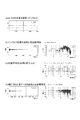
図2(a)は出力する基準音の波形を示している。基準音は周波数特性がフラットな音を短時間出力するものであって、いわゆるインパルス応答のサンプリングである。 FIG. 2A shows the waveform of the reference sound to be output. The reference sound outputs a sound having a flat frequency characteristic for a short time, and is a so-called impulse response sampling.
図2(b)はこれを録音したときの音データの例を示している。時間と振幅のグラフからは、音の伝達の様子、すなわち残響(反射)によって音が伸びて届き、また減衰していく様子が示されている。周波数と音圧(dB)のグラフは第1の周波数特性(Impulse Response)を示しており、周波数によってよく届く音(ピーク)と、減衰してしまう音(ディップ)があることがわかる。なお周波数特性は、インパルス応答の波形をフーリエ変換することによって算出することができる。 FIG. 2B shows an example of sound data when this is recorded. The graph of time and amplitude shows how the sound is transmitted, that is, how the sound reaches and extends due to reverberation (reflection) and attenuates. The graph of frequency and sound pressure (dB) shows the first frequency characteristic (Impulse Response), and it can be seen that there is a sound that reaches well with the frequency (peak) and a sound that attenuates (dip). The frequency characteristics can be calculated by Fourier transforming the impulse response waveform.
ところで、音には波長があるため、反射位置が遠い(遅延時間が長い)ときには変動が細かくなり、反射位置が近い(遅延時間が短い)ときには変動が緩やかになる。すなわち、図2(b)のうち周波数と音圧のグラフを参照すれば、細かな波と大きな波とを感じることができるが、細かな波は主として遠い壁からの反射によるもの(環境に依存するもの)であり、大きな波は主としてダミーヘッド内の影響によるものと捉えることができる。従って、細かな変動を残しつつ大きな変動を排除すれば、環境に依存する臨場感や残響感を保持したまま、ダミーヘッド固有の影響を排除することができることになる。なお、実際にはさらにスピーカやマイクの周波数特性も考慮すべきであるが、本実施例では説明の簡便のために省略する。 By the way, since the sound has a wavelength, the fluctuation becomes fine when the reflection position is far (the delay time is long), and the fluctuation becomes gentle when the reflection position is close (the delay time is short). That is, referring to the graph of frequency and sound pressure in FIG. 2B, a fine wave and a large wave can be felt, but the fine wave is mainly due to reflection from a far wall (depending on the environment). It can be understood that the large wave is mainly due to the influence in the dummy head. Therefore, if a large fluctuation is eliminated while leaving a fine fluctuation, the influence unique to the dummy head can be eliminated while maintaining the presence and reverberation depending on the environment. In practice, the frequency characteristics of speakers and microphones should be considered, but in this embodiment, they are omitted for the sake of simplicity.
そこで、図2(c)に示すように、周波数特性について所定の間隔で対数平均化処理をして、第2の周波数特性(Impulse Response Average)を算出する。対数平均とは自然対数をとった値の平均である。ここで平均は振幅のみについて行い、位相情報は残したままとする。位相情報もあわせて平均化してしまうと、波形が著しく減衰してしまうからである。 Therefore, as shown in FIG. 2C, the logarithmic averaging process is performed on the frequency characteristics at a predetermined interval to calculate a second frequency characteristic (Impulse Response Average). The logarithmic average is the average of the values obtained by taking the natural logarithm. Here, averaging is performed only on the amplitude, and the phase information remains. This is because if the phase information is also averaged, the waveform is significantly attenuated.
所定の間隔とは、適宜調整すべき値である。すなわち、間隔を広げるほどに対数平均化処理された波形は変動がゆるやかとなり、よりダミーヘッド内の影響のみに依存し、環境依存の波形を残すこととなる。しかしあまり緩やかにするとダミーヘッド内の影響をも再現することができなくなってしまい、本来の作用効果を奏しなくなってしまう。そこでシステムの感度や目的とするリファレンスフィルタの精度を鑑みて、適宜設定する必要がある。 The predetermined interval is a value to be adjusted as appropriate. That is, as the interval is increased, the logarithmically averaged waveform changes more slowly, and depends on only the influence in the dummy head, leaving an environment-dependent waveform. However, if it is too loose, the influence in the dummy head cannot be reproduced, and the original function and effect cannot be achieved. Therefore, it is necessary to set appropriately in consideration of the sensitivity of the system and the accuracy of the target reference filter.
そして、同じく図2(c)に示すように、対数平均化処理された波形(Impulse Response Average)に対し、位相を逆転させることにより逆フィルタ(Inverse Filter)(一時フィルタ)を生成する。この逆フィルタと最初に求めた第1の周波数特性とを乗算(畳み込み積分)することにより、第1の周波数特性を補正し、第3の周波数特性を生成する。 Similarly, as shown in FIG. 2C, an inverse filter (temporary filter) is generated by reversing the phase of the logarithm averaged waveform (Impulse Response Average). By multiplying (convolution integration) this inverse filter and the first frequency characteristic obtained first, the first frequency characteristic is corrected and a third frequency characteristic is generated.
図2(d)は、補正された音データの波形と周波数特性を示している。ここで周波数と音圧のグラフを参照すれば、第3の周波数特性においては大きな変動はなくなり、全体的な特性がフラットになっていることがわかる。そして、細かな変動は環境に依存する変動を示しているのである。この周波数特性をフーリエ変換したものが、時間と振幅のグラフに示されている。 FIG. 2D shows the waveform and frequency characteristics of the corrected sound data. Here, referring to the graph of frequency and sound pressure, it can be seen that there is no large variation in the third frequency characteristic, and the overall characteristic is flat. Minor fluctuations indicate fluctuations depending on the environment. A result of Fourier transform of this frequency characteristic is shown in a graph of time and amplitude.
さて、図2(a)に示したような基準音を発しようとしたときに、図2(d)の時間と振幅のグラフに示されるような音を発するように変換すれば、例えばヘッドホンで聴いているときにも、あたかもコンサートホールで聞いているような感覚を再現することができる。そこで第3の周波数特性を基に、これを再現するフィルタをFIRフィルタによって生成し、このリファレンスフィルタを介して再生することにより、上記の音響効果を得ることができる。 Now, when the reference sound as shown in FIG. 2 (a) is to be emitted and converted to emit the sound as shown in the time and amplitude graph of FIG. 2 (d), for example, with headphones. Even when listening, you can reproduce the feeling as if you were listening in a concert hall. Therefore, based on the third frequency characteristic, a filter that reproduces this is generated by an FIR filter and reproduced through this reference filter, whereby the above-described acoustic effect can be obtained.
ここで、FIRフィルタを用いることにより、極めて精緻な再現性を有するリファレンスフィルタとすることができる。そして上述した如く、FIRフィルタを生成する前処理として全体的な周波数特性をフラットにしたことにより、ダミーヘッド固有の影響を排除し、臨場感や残響感を保持したまま音質を向上させるリファレンスフィルタとすることができる。 Here, by using the FIR filter, a reference filter having extremely fine reproducibility can be obtained. As described above, by making the overall frequency characteristic flat as preprocessing for generating the FIR filter, the reference filter which eliminates the influence of the dummy head and improves the sound quality while maintaining the sense of reality and reverberation, can do.
また、上記生成方法によれば、ダミーヘッド固有の影響を排除するために、ダミーヘッドを特別な無反響空間などに設置して別途サンプリングを行う必要がなく、リファレンスフィルタを得たい特定環境に設置してサンプリングするのみで足りる。従って、サンプリング作業の労力が軽減されると共に、実際の環境でダミーヘッドに届く音を用いて影響排除することができるため、より適切にダミーヘッド固有の影響を排除することができる。 In addition, according to the above generation method, it is not necessary to perform sampling separately by installing the dummy head in a special anechoic space or the like in order to eliminate the influence unique to the dummy head, and install it in a specific environment where a reference filter is desired. And sampling. Therefore, the labor of the sampling operation is reduced and the influence can be eliminated by using the sound that reaches the dummy head in the actual environment, so that the influence specific to the dummy head can be more appropriately eliminated.
[増幅レベルと遅延時間の補正]
次に、増幅レベルと遅延時間の補正について、図3を用いて説明する。本補正は上記C11、C12、C21、C22の4パターンで取得した音データについて、それぞれの増幅レベルと遅延時間を補正するものである。
[Amplification level and delay time correction]
Next, the correction of the amplification level and the delay time will be described with reference to FIG. This correction corrects each amplification level and delay time for the sound data acquired in the four patterns C11, C12, C21, and C22.
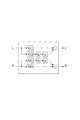
図3に示すように、リファレンスフィルタ8は、C11、C12、C21、C22にそれぞれ対応するフィルタR11、R12、R21、R22を備えている。それぞれのフィルタはFIRフィルタにて構成されている。 As shown in FIG. 3, the reference filter 8 includes filters R11, R12, R21, and R22 corresponding to C11, C12, C21, and C22, respectively. Each filter is configured by an FIR filter.
ダミーヘッド1を用いて基準音のサンプリングを行う場合、スピーカL、Rと測定位置の位置関係、壁からの反射の状況により、図3の「インパルス応答」の欄に示すように、左右のマイク2L、2Rの信号レベルと遅延時間に差が生じる場合がある。これらが均等になるまで取り直しをすることも考えられるが、サンプリング作業の負担が増大するという問題がある。
When sampling the reference sound using the
信号レベルおよび遅延時間に差が生じたままでリファレンスフィルタ8を生成すると、後にこのフィルタを用いて再生した音にも、同様の差が再現されてしまう。すると、音源の定位を試聴者の前方に設定したいところが、ずれて聞こえてしまうのである。 If the reference filter 8 is generated with a difference between the signal level and the delay time, the same difference is also reproduced in the sound reproduced later using this filter. Then, the place where the sound source localization is to be set in front of the listener is heard with a deviation.
そこで本実施例においては、振幅波形における正方向の最初のピークを第1パスと称すると、C11〜C22の全ての第1パスの増幅レベルが一致するように補正する。さらに、C11とC22の第1パスの開始時間が一致するように補正する。ここでC12のC11に対する遅延時間d1、C21のC22に対する遅延時間d2は、そのまま保持する。そして補正後のインパルス応答を基に、リファレンスフィルタ8の個々のフィルタR11〜R22を生成する。すなわち、各フィルタR11〜R22は、増幅レベルおよび遅延時間について左右独立して設定する。 Therefore, in the present embodiment, when the first peak in the positive direction in the amplitude waveform is referred to as the first path, correction is performed so that the amplification levels of all the first paths C11 to C22 coincide. Further, correction is performed so that the start times of the first pass of C11 and C22 coincide. Here, the delay time d1 of C12 with respect to C11 and the delay time d2 of C21 with respect to C22 are maintained as they are. And based on the impulse response after correction | amendment, each filter R11-R22 of the reference filter 8 is produced | generated. That is, each of the filters R11 to R22 sets the amplification level and the delay time independently on the left and right.
具体的な方法としては、例えば、取得した音データをあらかじめ補正してからフィルタR11〜R22を生成する方法が考えられる。すなわちまず振幅波形のデータを基に音データのレベルを一致させるようにゲインを調節し、また遅延を補正した上で、フィルタR11〜R22を生成する。また他の方法として、とりあえず音データのレベルと遅延はそのままに各フィルタを生成し、その後にフィルタの増幅レベルと遅延時間を補正することでもよい。 As a specific method, for example, a method of generating the filters R11 to R22 after correcting the acquired sound data in advance can be considered. That is, first, the gains are adjusted to match the sound data levels based on the amplitude waveform data, and the delays are corrected, and then the filters R11 to R22 are generated. As another method, it is possible to generate each filter without changing the level and delay of the sound data for the time being, and then correct the amplification level and delay time of the filter.
上記の如く構成したことにより、音源の定位を試聴者の前方に設定することができるため、試聴者は安定感をもって音を聞くことができる。またクロストークの遅延時間を保持するように構成したことにより、臨場感(広がり感)を保持することができる。 By configuring as described above, the sound source can be positioned in front of the listener, so that the listener can hear the sound with a sense of stability. Further, since the configuration is such that the delay time of the crosstalk is maintained, it is possible to maintain a sense of presence (a feeling of spread).
[クロストークのレベルと遅延時間の補正]
次に、クロストークのレベルと遅延時間の補正について、図4を用いて説明する。図4に示すように、それぞれのフィルタR11、R12、R21、R22のうち、左のスピーカLから出力して右のマイク2Rに入力したC12の音データから生成したフィルタR12、および右のスピーカRから出力して左のマイク2Lに入力したC21の音データから生成したフィルタR21は、クロストークフィルタである。
[Correction of crosstalk level and delay time]
Next, correction of the crosstalk level and the delay time will be described with reference to FIG. As shown in FIG. 4, among the filters R11, R12, R21, and R22, the filter R12 generated from the sound data of C12 output from the left speaker L and input to the
クロストークについて概略を説明すれば、左右一方側(例えば左)の音源から他方側(例えば右)の耳に到達する音のことをクロストークという。このクロストークに用いられるフィルタを、本実施例ではクロストークフィルタと称する。すなわち、クロストークフィルタは、対角のスピーカとマイクとの間で取得された音データを基に生成したフィルタR12、R21である。 To explain the outline of crosstalk, the sound that reaches the ear on the other side (for example, right) from the sound source on one side (for example, left) is called crosstalk. The filter used for this crosstalk is referred to as a crosstalk filter in this embodiment. That is, the crosstalk filter is filters R12 and R21 generated based on sound data acquired between a diagonal speaker and a microphone.
図3を用いた説明にあっては、クロストークフィルタR12、R21はフィルタR11、R22とレベルを同一とし、遅延時間は保持したままとした。しかし、さらにクロストークのレベルと遅延時間を変化させることにより、異なる音響効果を得ることができる。具体的には、クロストークのレベルを強くすれば臨場感が増大し、レベルを小さくすれば定位が向上する。また左右のクロストークの遅延時間を調整することにより、定位の位置を調整することができる。 In the description using FIG. 3, the levels of the crosstalk filters R12 and R21 are the same as the filters R11 and R22, and the delay time is maintained. However, different acoustic effects can be obtained by further changing the crosstalk level and the delay time. Specifically, if the level of crosstalk is increased, the sense of presence increases, and if the level is decreased, the localization is improved. Further, the position of localization can be adjusted by adjusting the delay time of the left and right crosstalk.
そこで本実施例では、クロストークフィルタを加算する際の割合レベル(ゲイン)および遅延時間について、それぞれを左右独立に設定可能としている。図4においてGのブロックはゲインの調整手段を示し、dのブロックは遅延の調整手段を示している。 Therefore, in this embodiment, the ratio level (gain) and delay time when adding the crosstalk filter can be set independently for the left and right. In FIG. 4, a block G represents gain adjusting means, and a block d represents delay adjusting means.
上記の如く構成したことにより、臨場感と定位も設定可能なリファレンスフィルタを生成することができる。なお、クロストークフィルタのレベルと遅延時間の設定は、リファレンスフィルタの生成時に行うことでもよいが、再生時に動的にパラメータを変更することが可能なように構成してもよい。 By configuring as described above, it is possible to generate a reference filter that can also set the presence and the localization. The setting of the level of the crosstalk filter and the delay time may be performed when the reference filter is generated, but may be configured so that the parameters can be dynamically changed during reproduction.
以上、添付図面を参照しながら本発明の好適な実施形態について説明したが、本発明は係る例に限定されないことはいうまでもない。当業者であれば、特許請求の範囲に記載された範疇内において、各種の変更例または修正例に想到しうることは明らかであり、それらについても当然に本発明の技術的範囲に属するものと了解される。 As mentioned above, although preferred embodiment of this invention was described referring an accompanying drawing, it cannot be overemphasized that this invention is not limited to the example which concerns. It will be apparent to those skilled in the art that various changes and modifications can be made within the scope of the claims, and these are naturally within the technical scope of the present invention. Understood.
本発明は、リファレンス環境においてダミーヘッドを用いて採取した音声からリファレンスフィルタを生成する方法として利用することができる。 The present invention can be used as a method for generating a reference filter from speech collected using a dummy head in a reference environment.
L …左スピーカ
R …右スピーカ
1 …ダミーヘッド
2 …マイク
3 …録音部
4 …演算部
5 …記録部
6 …出力部
7 …操作入力部
8 …リファレンスフィルタ
L ... Left speaker R ...
Claims (5)
前記第1の周波数特性において振幅のみを周波数について所定間隔で対数平均化処理を行って第2の周波数特性を算出し、
前記対数平均化処理された第2の周波数特性の位相を反転させることで逆の特性を有する一時フィルタを生成し、
前記一時フィルタと前記第1の周波数特性とを乗算することにより第3の周波数特性を算出し、
前記第3の周波数特性からフィルタ係数を生成することを特徴とするリファレンスフィルタの生成方法。 Obtaining sound data emitted from a sound source with a microphone provided in the dummy head , calculating a first frequency characteristic serving as a transfer characteristic from the sound source to the microphone ,
The only Oite amplitude calculating a second frequency characteristic by performing a logarithmic averaging process at predetermined intervals for the frequency to the first frequency characteristic,
Generating a temporary filter having a reverse characteristic by inverting the phase of the logarithm-averaged second frequency characteristic;
Calculating a third frequency characteristic Ri by the multiplying the said and the one o'clock filter first frequency characteristic,
A reference filter generation method, wherein a filter coefficient is generated from the third frequency characteristic.
前記左側のフィルタと前記右側のフィルタとの増幅レベルを左右独立して設定することを特徴とする請求項1記載のリファレンスフィルタの生成方法。 The reference filter is provided with a left and right filter generated based on the sound data acquired by the microphone provided in at least the dummy head,
2. The reference filter generation method according to claim 1, wherein amplification levels of the left filter and the right filter are set independently on the left and right.
前記左側のフィルタと前記右側のフィルタとの遅延時間を左右独立して設定することを特徴とする請求項1記載のリファレンスフィルタの生成方法。 The reference filter is provided with a left and right filter generated based on the sound data acquired by the microphone provided in at least the dummy head,
The reference filter generation method according to claim 1, wherein a delay time between the left filter and the right filter is set independently on the left and right.
前記他方側の音源から前記ダミーヘッドの該他方側の耳のマイクに到達した音データに基づいてフィルタをそれぞれ生成し、
前記フィルタの出力信号に前記クロストークフィルタの出力信号を加算する際に、加算する割合を左右独立して設定可能であることを特徴とする請求項1記載のリファレンスフィルタの生成方法。 At least sounds emitted from the pair of left and right sound sources are acquired by microphones provided on the left and right ears of the dummy head, and crossed based on sound data that has reached the microphones of the other ear of the dummy head from the left and right sound sources. Generate a talk filter,
A filter is generated based on sound data that has reached the microphone on the other side of the dummy head from the sound source on the other side,
Method of generating a reference filter of claim 1, wherein the output signal of the filter when adding the output signal of the crosstalk filter can be set the rate for adding the left and right independently.
Priority Applications (1)
| Application Number | Priority Date | Filing Date | Title |
|---|---|---|---|
| JP2005099679A JP4845407B2 (en) | 2005-03-30 | 2005-03-30 | How to generate a reference filter |
Applications Claiming Priority (1)
| Application Number | Priority Date | Filing Date | Title |
|---|---|---|---|
| JP2005099679A JP4845407B2 (en) | 2005-03-30 | 2005-03-30 | How to generate a reference filter |
Publications (2)
| Publication Number | Publication Date |
|---|---|
| JP2006279862A JP2006279862A (en) | 2006-10-12 |
| JP4845407B2 true JP4845407B2 (en) | 2011-12-28 |
Family
ID=37214072
Family Applications (1)
| Application Number | Title | Priority Date | Filing Date |
|---|---|---|---|
| JP2005099679A Expired - Fee Related JP4845407B2 (en) | 2005-03-30 | 2005-03-30 | How to generate a reference filter |
Country Status (1)
| Country | Link |
|---|---|
| JP (1) | JP4845407B2 (en) |
Families Citing this family (2)
| Publication number | Priority date | Publication date | Assignee | Title |
|---|---|---|---|---|
| JP5891438B2 (en) * | 2012-03-16 | 2016-03-23 | パナソニックIpマネジメント株式会社 | Sound image localization apparatus, sound image localization processing method, and sound image localization processing program |
| JP6033152B2 (en) * | 2013-03-28 | 2016-11-30 | Kddi株式会社 | Reception quality measurement method, reception quality measurement device, and program |
Family Cites Families (4)
| Publication number | Priority date | Publication date | Assignee | Title |
|---|---|---|---|---|
| JPH05153698A (en) * | 1991-11-27 | 1993-06-18 | Fujitsu Ten Ltd | Sound field enlargement controller |
| JP2755081B2 (en) * | 1992-11-30 | 1998-05-20 | 日本ビクター株式会社 | Sound image localization control method |
| JP2827777B2 (en) * | 1992-12-11 | 1998-11-25 | 日本ビクター株式会社 | Method for calculating intermediate transfer characteristics in sound image localization control and sound image localization control method and apparatus using the same |
| JP2004361573A (en) * | 2003-06-03 | 2004-12-24 | Mitsubishi Electric Corp | Acoustic signal processor |
-
2005
- 2005-03-30 JP JP2005099679A patent/JP4845407B2/en not_active Expired - Fee Related
Also Published As
| Publication number | Publication date |
|---|---|
| JP2006279862A (en) | 2006-10-12 |
Similar Documents
| Publication | Publication Date | Title |
|---|---|---|
| US10104485B2 (en) | Headphone response measurement and equalization | |
| US6909041B2 (en) | Sound field control method and sound field control system | |
| US9635484B2 (en) | Methods and devices for reproducing surround audio signals | |
| US5742688A (en) | Sound field controller and control method | |
| JP3823824B2 (en) | Electronic musical sound generator and signal processing characteristic adjustment method | |
| US9577595B2 (en) | Sound processing apparatus, sound processing method, and program | |
| KR20050060789A (en) | Apparatus and method for controlling virtual sound | |
| JP2012004668A (en) | Head transmission function generation device, head transmission function generation method, and audio signal processing apparatus | |
| JPH10247089A (en) | Playing sound filed controller | |
| US8031883B2 (en) | Crosstalk cancellation system with sound quality preservation and parameter determining method thereof | |
| JP2016524862A (en) | Spatially selective audio playback apparatus and method | |
| JPH09322299A (en) | Sound image localization controller | |
| JP2006517072A (en) | Method and apparatus for controlling playback unit using multi-channel signal | |
| JP2012509632A (en) | Converter and method for converting audio signals. | |
| JP2010157852A (en) | Sound corrector, sound measurement device, sound reproducer, sound correction method, and sound measurement method | |
| JP2006279863A (en) | Correction method of head-related transfer function | |
| JPH10304498A (en) | Stereophonic extension device and sound field extension device | |
| JP2007329631A (en) | Acoustic correction device | |
| JP4845407B2 (en) | How to generate a reference filter | |
| US20080285768A1 (en) | Method and System for Modifying and Audio Signal, and Filter System for Modifying an Electrical Signal | |
| JP2007336080A (en) | Sound compensation device | |
| JPH0833092A (en) | Design device for transfer function correction filter of stereophonic reproducing device | |
| JP2714098B2 (en) | How to correct acoustic frequency characteristics | |
| JP3579508B2 (en) | Audio equipment | |
| JPH08102999A (en) | Stereophonic sound reproducing device |
Legal Events
| Date | Code | Title | Description |
|---|---|---|---|
| A621 | Written request for application examination |
Free format text: JAPANESE INTERMEDIATE CODE: A621 Effective date: 20080318 |
|
| A131 | Notification of reasons for refusal |
Free format text: JAPANESE INTERMEDIATE CODE: A131 Effective date: 20110111 |
|
| TRDD | Decision of grant or rejection written | ||
| A01 | Written decision to grant a patent or to grant a registration (utility model) |
Free format text: JAPANESE INTERMEDIATE CODE: A01 Effective date: 20111011 |
|
| A01 | Written decision to grant a patent or to grant a registration (utility model) |
Free format text: JAPANESE INTERMEDIATE CODE: A01 |
|
| A61 | First payment of annual fees (during grant procedure) |
Free format text: JAPANESE INTERMEDIATE CODE: A61 Effective date: 20111011 |
|
| FPAY | Renewal fee payment (event date is renewal date of database) |
Free format text: PAYMENT UNTIL: 20141021 Year of fee payment: 3 |
|
| R150 | Certificate of patent or registration of utility model |
Ref document number: 4845407 Country of ref document: JP Free format text: JAPANESE INTERMEDIATE CODE: R150 Free format text: JAPANESE INTERMEDIATE CODE: R150 |
|
| R250 | Receipt of annual fees |
Free format text: JAPANESE INTERMEDIATE CODE: R250 |
|
| R250 | Receipt of annual fees |
Free format text: JAPANESE INTERMEDIATE CODE: R250 |
|
| R250 | Receipt of annual fees |
Free format text: JAPANESE INTERMEDIATE CODE: R250 |
|
| R250 | Receipt of annual fees |
Free format text: JAPANESE INTERMEDIATE CODE: R250 |
|
| R250 | Receipt of annual fees |
Free format text: JAPANESE INTERMEDIATE CODE: R250 |
|
| R250 | Receipt of annual fees |
Free format text: JAPANESE INTERMEDIATE CODE: R250 |
|
| LAPS | Cancellation because of no payment of annual fees |