JP4845307B2 - Detection array using a three-dimensional substrate - Google Patents
Detection array using a three-dimensional substrate Download PDFInfo
- Publication number
- JP4845307B2 JP4845307B2 JP2001292362A JP2001292362A JP4845307B2 JP 4845307 B2 JP4845307 B2 JP 4845307B2 JP 2001292362 A JP2001292362 A JP 2001292362A JP 2001292362 A JP2001292362 A JP 2001292362A JP 4845307 B2 JP4845307 B2 JP 4845307B2
- Authority
- JP
- Japan
- Prior art keywords
- substrate
- nucleic acid
- acid probe
- array
- reaction
- Prior art date
- Legal status (The legal status is an assumption and is not a legal conclusion. Google has not performed a legal analysis and makes no representation as to the accuracy of the status listed.)
- Expired - Fee Related
Links
Images


Description
【0001】
【発明の属する技術分野】
本発明は、生物学的試料中の被検物質を特異親和性物質を用いて検出するための検出用アレイであって、詳しくは、特異親和性物質としてのプローブを立体状基体の表面に固相化したプローブアレイに関する。
【0002】
【従来の技術】
生物学的な特異結合反応を利用する検出方法、例えば、ハイブリダイゼーションを利用する核酸の検出方法等は一般的に広く使用されている。また、そのような方法においてハイブリダイゼーションを行うための装置も数多く開発されている。
【0003】
例えば、コーニング社はDNAマイクロアレイ専用のスライドガラスとして、アミノシランコートのCMT−GAPSを提供している。このスライドガラスは、一定規格、即ち、約7.5cm×約2.5cmの平面状のスライドガラスであり、プローブアレイの基板として使用されている。使用者は、その表面に検出されるべき核酸に特異的な核酸プローブを、多種類、別々に固相化して使用する。このようなスライドガラスを用いる手段は、他の手段に比較して安価であることや、プローブの固相化が容易であること等の利点を有する反面、ハイブリダイゼーション反応での反応むらが問題となっている。
【0004】
また一方で、半導体基板上にプローブDNAを高密度で配置するジーンチップTMがアフィメトリックス社(Affymetrix)から提供されている(米国特許第5,143,854号等を参照されたい)。ジーンチップTMは、2cm×2cmの平面状の半導体基板の片面にフォトリソグラフィー技術によって高密度に多種類のプローブDNAを別々に固相した一種の核酸プローブアレイである。また、米国特許第5,843,767号には、厚さが約10μmから約500μmの半導体基板において、口径が約5μmから約2mmの貫通孔を多数形成して、プローブDNAを各貫通孔の内壁に固相することによって、表面積を増加させた核酸プローブアレイが開示されている。
【0005】
このように、従来、使用される核酸プローブアレイは、何れも平面板状の基板を使用している。しかしながら、このような従来の平板状基板では、核酸プローブアレイ作製過程およびハイブリダイゼーション反応過程において、少なくとも所要の反応時間の間は蒸発しない程度の液量となるように、多量の反応用溶液、例えば、検体、洗浄用溶液および標識ターゲットDNA等の試薬を必要とするので、多量の基板を処理するのは不向きである。
【0006】
また、平板状の基体は、基体の表面の利用部分が少なく、少なくとも片方の基板面を固相のために使用していない。また、平板状の基体は、必要な反応部分全体を検体と接触させるために余分量を要求するとともに、各反応部分における分注精度が変動し易いので、再現性が低い反応結果が得られる可能性がある。
【0007】
他方、表面積を増加する例として、特定種類の特異親和性結合試薬を含む溶液中に直径が数μmのビーズを混合して試薬を固相化し、反応容器中で検体と反応させた後に、自由な向きで浮遊または容器底面に沈降しているビーズに対して蛍光等の光出力の合計を測定するようなビーズ状の基体も公知であるが、基体表面における位置情報を得ることができないので、検査項目の結果の取り違いを生じ得る。
【0008】
更に、複数の異なる検体のそれぞれに対応して反応および/または測定すべき複数の基体を互いに区別する適切な方法が提供されていないので、検体の取り違いを生じ得る。また、同時にまたは連続的に複数の異なる検査を実行する場合に、各々の検査状況を区別して把握することが困難である。
【0009】
【発明が解決しようとする課題】
このような状況に鑑み、本発明は、各作業工程で必要とされる試薬を少量化し、且つ検出用アレイの何れの位置においても反応むらを生じることなく処理を実施でき、また、多くの数量を一度に簡便に且つ反応むらなく安定して処理できる検出用アレイを提供することを目的とする。
【0010】
【課題を解決するための手段】
発明者等は、鋭意研究の結果、従来は平板上に特異親和性物質を固相化していた平板状のチップ状アレイを、3次元的な立体状基体である球状に変更するという大胆な発想に基づいて、上記の課題を解決し目的を達成する手段を開発した。即ち、本発明は、少なくとも1個の立体状基体と、複数種類の被検物質に対して夫々特異的に結合する複数種類の特異親和性物質を該立体状基体の特定位置の表面に部分的に固相化された特異親和性プローブと、前記特異親和性プローブの前記基体表面での配置を判別するための位置検出用マーカーとを具備する検出用アレイである。
【0011】
【発明の実施の形態】
[特異親和性物質]
本発明の特異親和性物質は、例えば、遺伝子等の核酸を含む物質、抗原、抗体、アレルゲン、ホルモンおよび酵素等を含む。
【0012】
[核酸プローブアレイ]
本発明の核酸プローブアレイは、立体状基体と、該立体状基体の表面に固相化された核酸プローブとを具備する。好ましくは前記立体状基体は、粒状であり、更に好ましくは、少なくとも1部分に曲面を有し、特に、曲面体が好ましく、最も好ましくは真球である。
【0013】
[立体状基体]
本発明のプローブアレイを構成する立体状基体は、1個または複数個で、3次元的表面を構成する基体を意味する。3次元的表面は、公知の検出技術により検出可能なレベルの領域を3次元的に備えており、好ましくは、少なくとも一部が曲面体を有している。
【0014】
[粒状基体]
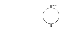
本核酸プローブアレイを構成する粒状基体は、約4.2×10⁻³mm3から約6.5×104cm3の体積を有する粒状基体である。本発明で使用される粒状基体の形態は粒状であればよく、具体的には、立方体、長方体および多面体等、並びにその一部に曲面を有する形体、例えば、球体、回転楕円体およびその他の回転体を含む。また、それらの形態は中空であってもよく、更に、それらの曲面体の2分割、3分割または4分割して得られる少なくとも一部に曲面も含む形体であってもよい。好ましい形体は真球である。しかしながら、これらに限られるものではない。ここで、上記の立方体基体、ひいては粒状基体において使用される「曲面体」の語は、真球(図1)、楕円回転体(図2)、半球(図3)、椀形(図4)、卵形、俵形、葉巻形、米形、ロケット形、円錐、円柱(細長の線維体を含む)、および流線形等の曲面で囲まれた何れの形体、並びにそれらの曲面に由来する一部曲面を有する形体を含むが、これに限られるものではない。しかし、製造工程の容易さから、真球または楕円回転体等の回転体が好ましい。
【0015】
ここで使用される「粒状」の語は、比較的小さな基体の大凡の形態を示す語であり、具体的な形状および大きさは本明細書に示す通りであり、板状である従来の基板に対比して使用され、部分的に核酸プローブが固相化され得るような曲面を少なくとも1部分に有しているものを意味する語である。
【0016】
該基体の体積は、約4.2×10⁻³mm3から約6.5×104cm3でよく、好ましくは約0.065mm3から約4.19cm3であり、より好ましくは約0.52mm3から約0.52cm3である。例えば、真球である場合、その直径は、固相化する特異親和性物質の種類の数によっては最大50cmであり得るが、実用上は、200μmから5cmでもよく、500μmから2cmが好ましく、1mmから1cmが最も好ましい。また、大きさの異なる担体を同時に同一の反応系において使用することも可能である。また、円錐や円柱等のように曲面部分と非曲面部分とを有する基体においては、例えば、断面の直径が2mm以下、特に1mm未満のような微小部分であるような基体である場合には、その長手部分を充分長く(例えば、1cmから50cm)するような組合せの細長い繊維体または棒状体を、適宜不定形もしくは螺旋状に曲げることによって、球状、円錐状、円筒状等に縮小化した3次元構造の立方体(例えば、200μmから1cmの平均直径および/または1mmから5cmの長手部分)であってもよい。
【0017】
本発明で使用される粒状基体は、ガラス、プラスチック素材、磁性体、ゼラチン、ゴム、タンパク、シリコン等を単独で、または適宜、混合、封入、積層化することによって種々の所要特性(剛性、気密性、表面粗さ、比重、光透過性、溶解度、電荷、吸水性、色相、明度)を付与して製造することが可能であるが、これに限定されるものではない。
【0018】
該粒状基体は、その材質に応じたそれ自身公知の手段により形成することが可能である。例えば、ガラスを材料とする場合には、型取りまたは研磨を行うことにより所望する形体が得られる。プラスチック素材においては、射出成形または型取りを行うことで球状に加工するが、これらの方法に限定されるものではない。また、コアセルベーションのように液相から固相を形成する方法や毛玉状若しくは円筒状に繊維性素材を巻いて固化する方法等によって造粒された球体、多角粒体、異形粒体も使用できる。基体の立方性を維持するために、骨格となる種々の硬性部材に対して、核酸を固相するのに適した素材を被覆、巻き付け、植え付け等することによって製造コストを低減するようにしてもよい。
【0019】
また、該粒状基体の表面は、核酸プローブを固相化するために適切な程度に滑らかであることが好ましい。また、該基体の表面は、核酸プローブを固相化するために適切な表面処理、例えば、ポリLリジン処理、アミノシラン処理および酸化膜処理等の表面処理を行うことが可能である。
【0020】
本発明の核酸プローブアレイの大きな特徴は、核酸プローブを固相するための基体として、少なくとも1部分に曲面を有する粒状基体を使用することである。曲面は、従来から使用される同体積の平板状の基体と比較して、その表面積が顕著に大きい。即ち、本発明において用いる粒状基体は、直径を同じとする板状基体の面積が4r2であるのと比較して、球の表面積は4πr2であるので、約3倍の表面積が得られる。従って、小さな基体上でより多数のプローブDNAを配することが可能となり、これによって実装密度の向上が図れるので省資源化が達成できる。また、後述する通り、ハイブリダイゼーション反応を行う際にも必要な試料量も低減でき、同時に、使用した全ての核酸プローブアレイにおいて等しく安定した反応を行うことが可能である。
【0021】
また、該基体に核酸プローブを固相化する際に、核酸プローブの基体表面での配置を判別するために、何らかの位置決め用のマーカーを設けるのが好ましい。このようなマーカーを施す方法は、複数の突起部や凹部または溝を設けること、核酸プローブそのものに標識すること、および基体表面への凹凸部を伴わなず、且つ光学的検出が可能な標識を行うこと等の手段を用いることが可能である。また、1つの基体に複数のマーカーを付すことも可能である。特に、3点のマーカーを付すことは、任意の同一または異なる複数個の核酸プローブに関する各固相化位置を容易に認識できることから好ましい。
【0022】
[核酸プローブ]
本発明の核酸プローブアレイにおいて固相される核酸プローブは、検出するべき核酸に対して相補的な配列を有する核酸であり、これにはDNAおよびRNA等が含まれる。また、プローブDNAとして、オリゴヌクレオチド、PCR産物等が用いられるが、これに限定されるものではない。塩基鎖の長さは、検出するべき核酸に応じて適宜決定してよい。また、核酸プローブを合成する場合、基体への固相に先駆けて予め合成しておくことも、また、基体上で合成することも可能である。
【0023】
[固相化方法]
該基体に所望する核酸プローブを固相するためのプローブ供給手段は、基体の材料によりそれ自身公知の何れかの手段を立体状基体若しくは粒状基体の曲面、特に球面に適用し得るように改良することにより行うことが可能である。例えば、曲面体に加工を施した基体上に核酸プローブを配するためには、光固相方式および点着方式の2つの手法を適宜組み合わせて用いることによって曲面の部分領域に対して定量的に核酸プローブを固相することが可能となる。更に、本発明では、プローブ供給手段と各種基体(好ましくは粒状基体、特に球状基体)とを立体面(好ましくは曲面、特に球面)に沿って相対的に移動させる手段を組み合わせることが重要である。
【0024】
光固相方式とは、フォトリソグラフ技術を応用したもので、基体を予めマスクしておき、反応部位のみを光照射して脱保護を行い、脱保護部分にのみ特異的に核酸プローブを固相する方法である。実際の固相において、複数種類の核酸プローブを固定する場合には、前記操作を繰り返す。光固相に適した粒状基体は、特に、シリコン類を用いたものが好ましく、例えば、球状シリコン基体を使用する場合、多結晶シリコンを加熱処理した後、ガラスチューブ等の内部で自然落下して冷却し、単結晶化することによって得られる(米国特許第5,955,776号を参照されたい)。
【0025】
また、光照射は、粒状基体用の連続露光装置等を用いることが可能である(特開平11-121368号を参照されたい)。この連続露光装置は、連続的に搬送される複数個の粒状基体を、基体の移動を停止することなく露光するものである。ここで、基体の曲面に沿った露光を実現するためには、基体を回転制御し得る構成で位置固定するのが好ましい。そこで、例えば、基体の粒状基体ホルダへの固定は、減圧により、または装置の環状部材の回転によって生じる遠心力によって行われる。少なくとも3つの超音波アクチュエーターを個別に動作させ、保持した球形基体を回転させることによって、粒状基体の位置調整を行うことが可能である。この装置に、更に、露光後の基体に核酸プローブを反応して結合する工程を行う部位、その後、粒状基体の洗浄および乾燥を行う部位を更に組み込むことによって、核酸プローブの光固相化装置として使用することが可能である。なお、球形基体のみならず、光源または光照射部位を回転あるいは変移させることも可能である。
【0026】
一方、点着方式は、プローブDNAを噴射するインクジェット方式または、ピンで接触することによりプローブDNAを付けるピン方式にて、該基体にプローブを固相する方法をいう。本発明のアレイを製造するために使用する点着装置は、球面を有する基体に対して、プローブDNA排出側であるインクジェットヘッドおよびピンを回転若しくは変移させること、または球状基体側を回転させまたは変移させること、およびこれらの組み合わせを行うことが可能であるものが望ましい。また、そのような装置は、1つの基体のみならず、複数個の基体の処理も連続的に行うことも可能であろう。
【0027】
また、該基体に核酸プローブを固相化する際に、基体表面における核酸プローブの配置を正確に行うため、また、検出を有利に行うために、何らかの位置決めマーカーを粒状基体に施すことが望ましい。このようなマーカーは、複数の突起部や凹部または溝を設けること、核酸プローブそのものに標識すること、および基体表面への凹凸部を伴わなず、且つ光学的検出が可能な標識を行うこと等の手段を用いることにより可能である。図5および6に突起部1を非対称または両極点に施した例を、図7に凹部2を対称および両極点に施した例を、また、図8に溝3を非対称に施した例を示すが、これに限定されるものではない。当該突起部の個数は、図に示すような1または2個に限らず、例えば、基体表面と容器内壁との接触が防止されるように十分な個数の突起部を設けてもよい。この場合、特定の突起部のみの寸法または形状を他の突起部と異ならせるようにして各核酸プローブの配置を把握し易くしてもよい。また、基体上の核酸プローブの配置の把握方法としては、突起または溝を設ける以外にも、検出用の標識とは異なる信号を発し得る信号発生手段であれば、蛍光、色素、磁気等、任意のものを使用してよく、更に、同一基体の異なる位置または異なる基体の各表面部分に対して複数種類の核酸プローブを固相化する場合には、信号発生手段を核酸プローブの種類毎に異なる信号量または信号パターンとなるように、色相、色素量、磁気量等を多様に設定するのが好ましい。かかる信号発生手段を用いれば、上記の位置検出用のマーカーを基体に設ける必要がなく、基体への固相位置を制御する必要もなくなるので、本発明の検出用アレイの製造を簡単且つ低コストにするという利点もある。
【0028】
また、核酸プローブの固相を行う際には、1つ1つの基体を固定して保持すると共に、装置との相対位置を精密に調製することが望ましい。従って、基体を回転させ、または変移させて精密な位置決めを行うと共に、調整後の位置に粒状基体を確実に保持することが必要である。このため、本発明の粒状基体は、図5から8に示すような1つまたは複数の突起部や凹部を設けることも可能である。これらを配置することにより、位置決めが容易になり、また、その部分を起点とした該基体の回転若しくは水平移動を容易に行うことが可能になる。また、ここに述べた複数個の突起部および凹部は、大きさや形状を変えることが可能である。
【0029】
本発明によれば、複数種類の特異親和性結合反応を実行するに当たり、固相工程および/または測定工程において基体と特異親和性結合試薬との位置関係を把握可能になっているので、同時にまたは連続的に複数の異なる検査を実行する場合に、各々の検査状況を区別して把握することが容易である。更に、複数の異なる検体を区別するために、複数の異なる検査用の基体(各1個以上)を別々の色、濃度、明暗の所望の組合せによって透光度、反射度、屈折度、偏光度等の光学的物性が異なるような複数種類の基体を検体毎に提供することができるので、個別の検体と基体の光学的物性とを対応付けて反応、測定、結果出力等を実行することによって、複数の異なる検体を同時または連続的に処理しても取り違いを生じ難いとうスループット、使い勝手、信頼性等の高さという画期的な利点も有する。
【0030】
[使用方法]
以下に、本発明の核酸プローブアレイの使用の例を示す。即ち、本発明の核酸プローブアレイを用いたDNAの検出方法の例を示す。
【0031】
先ず、上記の通りの方法に従って、所望するDNAプローブを該粒状基体に固相化して核酸プローブアレイを得る。この核酸プローブアレイに具備されるDNAプローブとターゲットDNAとの間でハイブリダイゼーション反応を行う。
【0032】
ここで、ターゲットDNAとして、追跡可能な標識分子、例えば、蛍光色素、発光色素等で標識されたもの、或いは該標的分子で標識されたプライマーで増幅し得るものを検体として使用することが考えられる。使用可能な標識は、Cy3、FITCおよびビオチン等であるが、これに限定されるものではない。また、非標識のターゲットDNAを用いて、ハイブリダイゼーション後の偏光性の変化を検出する方法なども使用可能である。
【0033】
好ましい使用例の1つを図9を用いて説明する。96ウェルのマイクロタイタープレートの1ウェルに本発明の核酸プローブアレイと、試薬を添加しハイブリダイゼーション反応を行う(図9)。このとき、該核酸プローブアレイは、直径6mmの真球基体と、核酸プローブとしてのDNAプローブを具備する。また、添加する試薬は約160μLである。適切な条件下でハイブリダイゼーションを行った後、プレートウォッシャーを用いて洗浄操作を行う。
【0034】
次に、もう1つの使用例を図10を用いて説明する。96ウェルのマイクロタイタープレートの1ウェルに本発明の核酸プローブアレイと試薬を添加しハイブリダイゼーション反応を行う(図10)。このとき、該核酸プローブアレイは、直径2mmの真球基体と、核酸プローブとしてのDNAプローブを具備し、1ウェル当り、約8個の核酸プローブアレイを添加する。ここで、8個の核酸プローブアレイの夫々には、互いに異なる1種または2種類以上の核酸プローブが固相化されているものとする。このように、複数個の基体に対して検出すべきターゲットDNAに対応する複数種類のDNAプローブを個別に、或いは、組み合わせて別々に固相化するようにすれば、基体1個当たりの製造コストを低減できるという利点もある。また、添加する試薬は約100μLである。適切な条件下でハイブリダイゼーションを行った後、プレートウォッシャー洗浄ノズルを用いて洗浄操作を行う。この場合、複数の基体には、標識可能な光学的または物理的標識が行われていることが望ましい。ターゲットDNAとしては1種類の標識ではなく2種類の標識以上のターゲットDNAを混合させて行うことも可能である。また、基体に磁性を持たせることにより、洗浄操作において、ウェルのある一部に多数基体を集積させることができ、それにより粒状基体が吸引されることを防止できる。このような洗浄操作後にアレイ上に残った標識物質の有無または量を、標識物質の基体上での位置または標識物質の種類毎に分類しながら適宜の計測手段およびデータ処理手段によって決定することができる。
【0035】
ハイブリダイゼーション反応および反応後の洗浄操作に適切な反応容器は、96ウェルマイクロタイタープレート等の所望の数の多穴を有するマイクロプレート、または0.2μLから1.5μLまでのマイクロチューブ等の汎用性のある容器が含まれるが、これに限られるものではない。また、反応容器として、フローセルや分注用ノズルのように管状のものでもよく、また、容器内がシリンジ等からの適当な圧力で凌駕され得る程度の毛管力を有する開口部を1箇所または複数箇所有するものであってもよい。
【0036】
また、ハイブリダイゼーション反応は、一般的に、45℃から65℃前後の恒温状態で、1時間から一晩の間、ターゲットDNAとの反応が行われるが、検出するべき核酸等の条件に応じて反応条件を変更することが可能である。
【0037】
従来は、ハイブリダイゼーション反応を試みる際、乾燥防止のためのカバーグラスを用いて静置状態で行っている。しかしながら、本発明の核酸プローブアレイを用いれば、チューブまたはウェル内にて、本アレイと試料を共存させ、振盪下または攪拌下で反応を実施できる。すなわち、容器中で、攪拌しながら該基体と検体とのハイブリダイゼーション反応を行うことが可能であるため、従来技術で問題となっている反応むらを回避することが可能であるとともに安定した反応を実施することができる。また、プローブDNAと標的DNAとの接触頻度が増加するので、ハイブリダイゼーション反応効率も上昇するという優れた効果が得られる。
【0038】
また、ハイブリダイゼーション反応および反応後の洗浄操作を、規格化されたマイクロタイタープレートにて行えば、洗浄等の操作をマイクロタイタープレート用ウォッシャー等を利用することが可能で、ハイブリダイゼーション反応から洗浄操作において自動化または半自動化が可能である。従って、本発明の核酸プローブアレイを汎用性のある容器と共に用いることによって、更に、洗浄操作における操作性の向上および洗浄時間短縮化も可能となる。
【0039】
また更に、本発明は、従来の核酸プローブアレイの同面積のものに比較して小型であるため、試薬および被検試料等の少量化が可能である。すなわち、粒状基体の直径を踏まえて、適切な反応容器を選択することによって、粒状基体を覆うのに十分なだけの少ない液量で反応及び洗浄を行うことが可能となり、試薬等の省資源化が図れる。また、1つの容器内において一度に多くの数量の核酸プローブアレイを反応に供することも可能である。また、反応容器に合わせて、粒状基体の直径を変えることも可能である。例えば、1ウェル当り1つの本核酸プローブアレイを使用する場合、96ウェルには約6から7mm、384ウェルには約3mmが好ましく使用できる。また、図10では、粒状基体の直径および個数が、ウェル内で、2層以上に積層する用に設定されているが、1層となるように設定すれば、2次元状で各基体の配置を把握できるのでより好ましい。また、大きさの異なる核酸プローブアレイを組み合わせて使用することにより、容器内のスペースを効率よく使用することが可能であり、それにより省資源化および省試薬化等を実現することが可能である。
【0040】
上述のように同一容器内での複数の基体を用いてハイブリダイゼーション反応を実施することで、1ウェル当り基体の表面積をより大きくでき、従ってより省資源化が図れる。また、大きさの異なる基体を組み合わせて使用することも可能である。このように使用することにより試薬の必要量を低減することが可能である。
【0041】
また、本発明の核酸プローブアレイを図11から14に示す容器と共に使用することも好ましい。図11に示すようにウェルまたは試験管の底をU字形にすることにより、反応溶液を少量化することが可能である。また、図12および13に示す通り、本発明の核酸プローブアレイに具備される基体に施された凹部または凸部(または突起部とも称する)に対応する凹部または凸部を容器に配することにより、球状の基体を容器中で安定して支持することが可能であり、これにより、球状、円筒状のように転がり易い形状を有する基体に関しても、該基体に具備される各核酸プローブの配置アドレスの把握も容易になると共に、基体上のDNAプローブが試験管底面と接触して隠れることなく充分な反応と洗浄を行える。また更に、図14に示す通り、該基体の特定部位に磁性14を設けることによって部分的ないし偏在的に部磁性を持たせ、且つ使用する容器の外部に磁石13を配置することによっても、同様に、該基体を一定の向きに安定に固定することが可能である。基体の特定部位に磁性体を配置させる方法としては、点着法、封入法等が挙げられる。尚、図12、13および14に示した基体の位置決めは、核酸プローブの固相処理や測定の際にも有効に利用できる。特に、図14に示した位置決め方法によれば、例えば、浅底の容器上で1個または複数個の基体を一定向きに固定した状態で固相処理や測定を同時または連続的に行える。更に、容器の下方で磁石を断続的に回転させるか、或いはU字状底面の側方へ磁石を移動させたり、側方で磁石を回転させることにより、あらゆる向きに基体を配向させることができるので、充分な表面積での固相化や測定が容易となる。
【0042】
【発明の効果】
基体を従来の平板状から、3次元的表面を有する立体状の形状として複数種類の特異親和性物質を固相化したことにより、多量のサンプル、試薬、洗浄液等の処理液を必要とせずに表面積を増加することが可能となった。それにより実装密度を向上することが可能となり、より多くのプローブを固定することが可能になった。従って、省資源化が可能である。
【0043】
さらに、特異親和性結合試薬との位置関係を把握可能になっているので、同時にまたは連続的に複数の異なる検査を実行する場合に、各々の検査状況を区別して把握することが容易である。
【図面の簡単な説明】
【図1】 真球形の球状基体を示す側面図。
【図2】 回転楕円形の球状基体を示す側面図。
【図3】 半球形の球状基体を示す側面図。
【図4】 椀形の球状基体を示す断面図。
【図5】 突起部を具備する真球形の球状基体を示す側面図。
【図6】 突起部を具備する真球形の球状基体を示す側面図。
【図7】 凹部を具備する真球形の球状基体を示す断面図。
【図8】 溝を具備する真球形の球状基体を示す側面図。
【図9】 本核酸プローブアレイの好ましい使用例を示す図。
【図10】 本核酸プローブアレイの好ましい使用例を示す図。
【図11】 本核酸プローブアレイを使用するための好ましい容器形状の例を示す図。
【図12】 本核酸プローブアレイを使用するための好ましい容器形状の例を示す図。
【図13】 本核酸プローブアレイを使用するための好ましい容器形状の例を示す図。
【図14】 本核酸プローブアレイを使用するための好ましい容器形状の例を示す図。
【符号の説明】
1.突起部 2.凹部 3.溝 4.反応容器 5.粒状基体
6.DNAプローブ 7.反応溶液 8.標識化ターゲットDNA
9.洗浄ノズル 10.磁性粒状基体
11.第1の標識化ターゲットDNA 12.第2の標識化ターゲットDNA
13.磁石 14.磁性部[0001]
BACKGROUND OF THE INVENTION
The present invention is a detection array for detecting a test substance in a biological sample using a specific affinity substance.As a specific affinity substanceProbeThree-dimensional substrateThe present invention relates to a probe array immobilized on a surface.
[0002]
[Prior art]
A detection method utilizing a biological specific binding reaction, for example, a nucleic acid detection method utilizing hybridization is generally used widely. Many apparatuses for performing hybridization in such a method have been developed.
[0003]
For example, Corning provides aminosilane-coated CMT-GAPS as a slide glass dedicated to DNA microarrays. This slide glass is a flat glass slide of a certain standard, that is, about 7.5 cm × about 2.5 cm, and is used as a substrate for a probe array. The user uses various kinds of nucleic acid probes specific to the nucleic acid to be detected on the surface thereof, separately immobilized. The means using such a glass slide has advantages such as being cheaper than other means and easy to immobilize the probe, but uneven reaction in the hybridization reaction is a problem. It has become.
[0004]
On the other hand, a gene chip that arranges probe DNAs on a semiconductor substrate at high densityTMAre provided by Affymetrix (see US Pat. No. 5,143,854, etc.). The gene chip TM is a kind of nucleic acid probe array in which many kinds of probe DNAs are separately solid-phased at high density on one side of a 2 cm × 2 cm flat semiconductor substrate by a photolithography technique. In US Pat. No. 5,843,767, a plurality of through-holes having a diameter of about 5 μm to about 2 mm are formed on a semiconductor substrate having a thickness of about 10 μm to about 500 μm, and probe DNA is attached to each through-hole. A nucleic acid probe array having an increased surface area by being solid-phased on the inner wall is disclosed.
[0005]
As described above, the conventional nucleic acid probe arrays each use a flat plate-like substrate. However, in such a conventional flat substrate, in a nucleic acid probe array preparation process and a hybridization reaction process, a large amount of reaction solution, for example, so that the amount of liquid does not evaporate at least during the required reaction time, for example, Since a reagent such as a specimen, a washing solution, and a labeled target DNA is required, it is not suitable for processing a large amount of substrates.
[0006]
Further, the flat substrate has a small portion of the surface of the substrate, and at least one substrate surface is not used for the solid phase. In addition, the flat substrate requires an extra amount to bring the entire necessary reaction part into contact with the specimen, and the dispensing accuracy in each reaction part is likely to fluctuate, so reaction results with low reproducibility can be obtained. There is sex.
[0007]
On the other hand, as an example of increasing the surface area, a bead with a diameter of several μm is mixed in a solution containing a specific type of specific affinity binding reagent to solidify the reagent and react with the sample in a reaction vessel. Also known is a bead-shaped substrate that measures the total light output, such as fluorescence, for beads that are floating or settled on the bottom of the container, but position information on the substrate surface cannot be obtained. Mistakes in the results of inspection items can occur.
[0008]
In addition, there is no provision of an appropriate method for differentiating a plurality of substrates to be reacted and / or measured corresponding to each of a plurality of different analytes, which can lead to sample mis-mixing. Also, when performing a plurality of different inspections simultaneously or successively, it is difficult to distinguish and grasp each inspection situation.
[0009]
[Problems to be solved by the invention]
In view of such circumstances, the present invention can reduce the amount of reagents required in each work step, and can carry out processing without causing reaction unevenness at any position of the detection array. An object of the present invention is to provide a detection array that can be easily and stably processed at a time without unevenness of reaction.
[0010]
[Means for Solving the Problems]
As a result of diligent research, the inventors have conventionally solidified a specific affinity substance on a flat plate.FlatChip array3D solid substrateBased on the bold idea of changing to a spherical shape, we have developed a means to solve the above problems and achieve the purpose. That is,The present inventionAt least one three-dimensional substrate and a plurality of types of specific affinity substances that specifically bind to a plurality of types of test substances are provided on the three-dimensional substrate.Specific locationOn the surfacePartiallySolid phase specific affinity probe andA position detection marker for discriminating the arrangement of the specific affinity probe on the substrate surfaceAnd an array for detection.
[0011]
DETAILED DESCRIPTION OF THE INVENTION
[Specific affinity substance]
Specific affinity substances of the present invention include, for example, substances containing nucleic acids such as genes, antigens, antibodies, allergens, hormones and enzymes.
[0012]
[Nucleic acid probe array]
The nucleic acid probe array of the present invention comprises a three-dimensional substrate and a nucleic acid probe immobilized on the surface of the three-dimensional substrate. Preferably, the three-dimensional substrate is granular, more preferably has a curved surface in at least one portion, a curved body is particularly preferable, and a true sphere is most preferable.
[0013]
[Three-dimensional substrate]
The three-dimensional substrate constituting the probe array of the present invention means one or a plurality of substrates constituting a three-dimensional surface. The three-dimensional surface has a three-dimensional region having a level that can be detected by a known detection technique, and preferably, at least a part thereof has a curved surface.
[0014]
[Granular substrate]
The granular substrate constituting the nucleic acid probe array is about 4.2 × 10⁻³mm3To about 6.5 × 104cm3A granular substrate having a volume of The form of the granular substrate used in the present invention is not particularly limited as long as it is granular, and specifically, a cube, a rectangular parallelepiped, a polyhedron, etc., and a shape having a curved surface in a part thereof, such as a sphere, a spheroid, and others Including a rotating body. Moreover, those forms may be hollow, and further, a form including a curved surface in at least a part obtained by dividing the curved body into two parts, three parts, or four parts. A preferred feature is a true sphere. However, the present invention is not limited to these. Here, the term “curved surface” used in the above-mentioned cubic base and thus granular base is a true sphere (FIG. 1), an elliptical rotator (FIG. 2), a hemisphere (FIG. 3), and a bowl (FIG. 4). , Egg-shaped, bowl-shaped, cigar-shaped, rice-shaped, rocket-shaped, conical, cylindrical (including elongated fiber bodies), and any shape surrounded by curved surfaces such as streamlines, and one derived from these curved surfaces Including, but not limited to, a shape having a partial curved surface. However, a rotating body such as a true sphere or an elliptical rotating body is preferable because of the ease of the manufacturing process.
[0015]
As used herein, the term “granular” is a word that indicates the general form of a relatively small substrate, the specific shape and size are as shown in this specification, and a conventional substrate having a plate shape. Is a term that means that a nucleic acid probe is partially solid-phased and has a curved surface in at least one part.
[0016]
The volume of the substrate is about 4.2 × 10⁻³mm3To about 6.5 × 104cm3Preferably about 0.065 mm3To about 4.19 cm3More preferably about 0.52 mm.3To about 0.52 cm3It is. For example, in the case of a true sphere, the diameter may be a maximum of 50 cm depending on the number of types of specific affinity substances to be immobilized, but in practice, it may be 200 μm to 5 cm, preferably 500 μm to 2 cm, preferably 1 mm To 1 cm is most preferred. It is also possible to simultaneously use carriers of different sizes in the same reaction system. In the case of a substrate having a curved surface portion and a non-curved surface portion such as a cone or a cylinder, for example, when the substrate has a cross-sectional diameter of 2 mm or less, particularly a minute portion such as less than 1 mm, A long and narrow fiber body or rod-like body that has a long enough length (for example, 1 to 50 cm) is reduced to a spherical shape, a conical shape, a cylindrical shape, or the like by appropriately bending it into an irregular shape or a
[0017]
The granular substrate used in the present invention can have various required properties (rigidity, airtightness) by mixing glass, plastic material, magnetic material, gelatin, rubber, protein, silicon, etc. alone, or by appropriately mixing, encapsulating, and laminating. Properties, surface roughness, specific gravity, light permeability, solubility, charge, water absorption, hue, brightness), but is not limited thereto.
[0018]
The granular substrate can be formed by means known per se according to the material. For example, when glass is used as a material, a desired shape can be obtained by molding or polishing. A plastic material is processed into a spherical shape by injection molding or molding, but is not limited to these methods. In addition, spheres, polygonal particles, and irregularly shaped particles that are granulated by a method of forming a solid phase from a liquid phase, such as coacervation, or a method of winding and solidifying a fibrous material in a pill-like or cylindrical shape can also be used. . In order to maintain the cubicity of the substrate, the manufacturing cost can be reduced by coating, winding, planting, etc., a material suitable for solid-phase nucleic acid to various rigid members as a skeleton. Good.
[0019]
Further, the surface of the granular substrate is preferably smooth to an appropriate level for immobilizing the nucleic acid probe. In addition, the surface of the substrate can be subjected to a surface treatment suitable for solidifying the nucleic acid probe, for example, a surface treatment such as poly-L-lysine treatment, aminosilane treatment, and oxide film treatment.
[0020]
A major feature of the nucleic acid probe array of the present invention is that a granular substrate having a curved surface in at least one part is used as a substrate for solid-phase nucleic acid probes. The curved surface has a remarkably large surface area compared to a flat substrate of the same volume that has been conventionally used. That is, the granular substrate used in the present invention has a plate-like substrate with the same diameter of 4r.2The surface area of the sphere is 4πr compared to2Therefore, a surface area about three times as large can be obtained. Accordingly, it becomes possible to arrange a larger number of probe DNAs on a small substrate, and this can improve the packaging density, thereby achieving resource saving. In addition, as will be described later, the amount of sample necessary for performing a hybridization reaction can be reduced, and at the same time, an equally stable reaction can be performed in all the nucleic acid probe arrays used.
[0021]
In addition, when the nucleic acid probe is immobilized on the substrate, it is preferable to provide some positioning marker in order to determine the arrangement of the nucleic acid probe on the substrate surface. The method of applying such a marker includes providing a plurality of protrusions, recesses or grooves, labeling the nucleic acid probe itself, and providing a label that is not accompanied by irregularities on the substrate surface and can be optically detected. It is possible to use means such as performing. It is also possible to attach a plurality of markers to one substrate. In particular, it is preferable to attach three markers because each immobilization position for any of the same or different nucleic acid probes can be easily recognized.
[0022]
[Nucleic acid probe]
The nucleic acid probe to be solid-phased in the nucleic acid probe array of the present invention is a nucleic acid having a sequence complementary to the nucleic acid to be detected, and includes DNA and RNA. In addition, oligonucleotides, PCR products, and the like are used as the probe DNA, but are not limited thereto. The length of the base chain may be appropriately determined according to the nucleic acid to be detected. When a nucleic acid probe is synthesized, it can be synthesized in advance prior to the solid phase on the substrate, or can be synthesized on the substrate.
[0023]
[Solidification method]
The probe supply means for immobilizing a desired nucleic acid probe on the substrate is modified so that any means known per se can be applied to the curved surface of a three-dimensional substrate or granular substrate, particularly a spherical surface, depending on the material of the substrate. Can be done. For example, in order to place a nucleic acid probe on a substrate with a curved surface processed, a combination of two methods, a photosolid phase method and a spotting method, can be used quantitatively with respect to a curved partial region. The nucleic acid probe can be solid-phased. Furthermore, in the present invention, it is important to combine a probe supply means and a means for relatively moving various substrates (preferably a granular substrate, particularly a spherical substrate) along a three-dimensional surface (preferably a curved surface, particularly a spherical surface). .
[0024]
The photo-solid phase method is an application of photolithographic technology. The substrate is masked in advance, the reaction site is irradiated with light to perform deprotection, and the nucleic acid probe is specifically immobilized only on the deprotected portion. It is a method to do. When a plurality of kinds of nucleic acid probes are immobilized on an actual solid phase, the above operation is repeated. The granular substrate suitable for the optical solid phase is particularly preferably one using silicon. For example, when a spherical silicon substrate is used, after the polycrystalline silicon is heat-treated, it is naturally dropped inside a glass tube or the like. Obtained by cooling and single crystallization (see US Pat. No. 5,955,776).
[0025]
For light irradiation, a continuous exposure apparatus for a granular substrate can be used (refer to JP-A-11-121368). This continuous exposure apparatus exposes a plurality of granular substrates that are continuously conveyed without stopping the movement of the substrates. Here, in order to realize exposure along the curved surface of the substrate, it is preferable to fix the position of the substrate so that the substrate can be rotationally controlled. Therefore, for example, the fixing of the substrate to the granular substrate holder is performed by a reduced pressure or a centrifugal force generated by the rotation of the annular member of the apparatus. It is possible to adjust the position of the granular substrate by individually operating at least three ultrasonic actuators and rotating the held spherical substrate. By further incorporating a part for performing the step of reacting and binding the nucleic acid probe to the substrate after exposure, and then a part for washing and drying the granular substrate, this apparatus can be used as an optical solid phase immobilization apparatus for the nucleic acid probe. It is possible to use. Note that it is possible to rotate or shift not only the spherical substrate but also the light source or the light irradiation site.
[0026]
On the other hand, the spotting method refers to a method in which a probe is solid-phased on the substrate by an inkjet method in which probe DNA is jetted or a pin method in which probe DNA is attached by contact with a pin. The spotting apparatus used to manufacture the array of the present invention is to rotate or shift the inkjet head and pins on the probe DNA discharge side, or rotate or change the spherical substrate side with respect to the substrate having a spherical surface. It is desirable to be able to perform these and combinations thereof. In addition, such an apparatus could continuously process not only one substrate but also a plurality of substrates.
[0027]
Further, when the nucleic acid probe is immobilized on the substrate, it is desirable to apply some positioning marker to the granular substrate in order to accurately arrange the nucleic acid probe on the surface of the substrate and to advantageously perform detection. Such markers are provided with a plurality of protrusions, recesses or grooves, labeled on the nucleic acid probe itself, and labeled with optical detection without accompanying irregularities on the substrate surface, etc. This is possible by using the following means. FIGS. 5 and 6 show an example in which the
[0028]
Further, when performing the solid phase of the nucleic acid probe, it is desirable to fix and hold each substrate and to precisely adjust the relative position with respect to the apparatus. Therefore, it is necessary to perform precise positioning by rotating or shifting the substrate, and to securely hold the granular substrate at the adjusted position. For this reason, the granular substrate of the present invention can be provided with one or a plurality of protrusions or recesses as shown in FIGS. By arranging these, positioning becomes easy, and it is possible to easily rotate or horizontally move the base body from that portion. Further, the size and shape of the plurality of protrusions and recesses described here can be changed.
[0029]
According to the present invention, when performing a plurality of types of specific affinity binding reactions, the positional relationship between the substrate and the specific affinity binding reagent can be grasped in the solid phase step and / or the measurement step. When a plurality of different inspections are continuously performed, it is easy to distinguish and grasp each inspection state. Furthermore, in order to distinguish a plurality of different specimens, a plurality of different test substrates (one or more of each) can be transmitted, reflected, refracted, or polarized by a desired combination of different colors, densities, and brightness. Since multiple types of substrates with different optical properties such as can be provided for each sample, by executing reaction, measurement, result output, etc. by associating the individual samples with the optical properties of the substrate Also, it has a revolutionary advantage of high throughput, ease of use, reliability and the like that hardly cause a difference even if a plurality of different specimens are processed simultaneously or continuously.
[0030]
[how to use]
Examples of use of the nucleic acid probe array of the present invention are shown below. That is, an example of a method for detecting DNA using the nucleic acid probe array of the present invention is shown.
[0031]
First, according to the method described above, a desired DNA probe is immobilized on the granular substrate to obtain a nucleic acid probe array. A hybridization reaction is performed between the DNA probe provided in the nucleic acid probe array and the target DNA.
[0032]
Here, as the target DNA, it is conceivable to use, as a sample, a traceable label molecule, for example, a label labeled with a fluorescent dye, a luminescent dye, or the like, or a substance that can be amplified with a primer labeled with the target molecule. . Labels that can be used include, but are not limited to, Cy3, FITC and biotin. In addition, a method of detecting a change in polarization after hybridization using an unlabeled target DNA can also be used.
[0033]
One preferred use example will be described with reference to FIG. A hybridization reaction is performed by adding the nucleic acid probe array of the present invention and a reagent to one well of a 96-well microtiter plate (FIG. 9). At this time, the nucleic acid probe array includes a true spherical substrate having a diameter of 6 mm and a DNA probe as a nucleic acid probe. The reagent to be added is about 160 μL. After hybridization under appropriate conditions, a washing operation is performed using a plate washer.
[0034]
Next, another usage example will be described with reference to FIG. The nucleic acid probe array of the present invention and a reagent are added to one well of a 96-well microtiter plate, and a hybridization reaction is performed (FIG. 10). At this time, the nucleic acid probe array includes a true spherical substrate having a diameter of 2 mm and a DNA probe as a nucleic acid probe, and about 8 nucleic acid probe arrays are added per well. Here, it is assumed that one or two or more different nucleic acid probes are immobilized on each of the eight nucleic acid probe arrays. In this way, if a plurality of types of DNA probes corresponding to target DNAs to be detected on a plurality of substrates are individually or combined and solid-phased separately, the production cost per substrate is increased. There is also an advantage that can be reduced. The reagent to be added is about 100 μL. After hybridization under appropriate conditions, a washing operation is performed using a plate washer washing nozzle. In this case, it is desirable that a plurality of substrates be provided with optically or physically labelable labels. The target DNA can be obtained by mixing not only one type of label but also two or more types of target DNA. Further, by providing magnetism to the substrate, it is possible to accumulate a large number of substrates in a part of the well in the cleaning operation, thereby preventing the granular substrate from being attracted. The presence / absence or amount of labeling substance remaining on the array after such a washing operation can be determined by appropriate measuring means and data processing means while classifying the labeling substance on the substrate or by the type of labeling substance. it can.
[0035]
Suitable reaction vessels for hybridization reactions and post-reaction washing operations are versatile, such as microplates with the desired number of multi-holes, such as 96-well microtiter plates, or microtubes from 0.2 μL to 1.5 μL. However, the present invention is not limited to this. The reaction vessel may be tubular like a flow cell or a dispensing nozzle, and has one or more openings having a capillary force that can be surpassed by appropriate pressure from a syringe or the like. You may have a place.
[0036]
The hybridization reaction is generally performed at a constant temperature of 45 ° C. to 65 ° C. for 1 hour to overnight, depending on conditions such as nucleic acid to be detected. It is possible to change the reaction conditions.
[0037]
Conventionally, when a hybridization reaction is attempted, it is performed in a stationary state using a cover glass for preventing drying. However, when the nucleic acid probe array of the present invention is used, the reaction can be carried out with shaking or stirring in the presence of the present array and sample in a tube or well.That is, since it is possible to perform a hybridization reaction between the substrate and the specimen while stirring in a container,It is possible to avoid the reaction unevenness that is a problem in the prior art.Stable reaction can be carried out. In addition, since the contact frequency between the probe DNA and the target DNA increases, an excellent effect of increasing the hybridization reaction efficiency can be obtained.
[0038]
In addition, if the hybridization reaction and the washing operation after the reaction are performed with a standardized microtiter plate, the washing operation can be performed using a washer for the microtiter plate, and the washing operation from the hybridization reaction. Can be automated or semi-automated. Therefore, by using the nucleic acid probe array of the present invention together with a versatile container, it is possible to further improve the operability and shorten the cleaning time in the cleaning operation.
[0039]
Furthermore,Since the present invention is smaller than a conventional nucleic acid probe array having the same area, the amount of reagents and test samples can be reduced. That is,By selecting an appropriate reaction vessel based on the diameter of the granular substrate, it is possible to perform the reaction and washing with a small amount of liquid sufficient to cover the granular substrate, and to save resources such as reagents. .It is also possible to subject a large number of nucleic acid probe arrays to the reaction in one container at a time.It is also possible to change the diameter of the granular substrate in accordance with the reaction vessel. For example, when one nucleic acid probe array is used per well, about 6 to 7 mm for 96 wells and about 3 mm for 384 wells can be preferably used. In FIG. 10, the diameter and the number of granular substrates are set to be laminated in two or more layers in the well. However, if they are set to be one layer, the arrangement of the substrates is two-dimensionally arranged. This is more preferable.Moreover, by using a combination of nucleic acid probe arrays of different sizes, it is possible to efficiently use the space in the container, thereby realizing resource saving and reagent saving. .
[0040]
By carrying out the hybridization reaction using a plurality of substrates in the same container as described above, the surface area of the substrate per well can be increased, and therefore resource saving can be achieved. It is also possible to use a combination of substrates having different sizes. By using in this way, it is possible to reduce the required amount of reagent.
[0041]
It is also preferable to use the nucleic acid probe array of the present invention together with the container shown in FIGS. As shown in FIG. 11, the reaction solution can be reduced in volume by making the bottom of the well or the test tube U-shaped. Further, as shown in FIGS. 12 and 13, by arranging a recess or projection corresponding to the recess or projection (or also referred to as a projection) provided on the substrate provided in the nucleic acid probe array of the present invention in the container. It is possible to stably support a spherical substrate in a container, so that the arrangement address of each nucleic acid probe included in the substrate can be obtained even for a substrate having a shape that is easy to roll, such as a spherical shape or a cylindrical shape. Can be easily grasped, and sufficient reaction and washing can be performed without the DNA probe on the substrate contacting the bottom surface of the test tube and hiding. Furthermore, as shown in FIG. 14, the same thing can be obtained by providing
[0042]
【The invention's effect】
BaseTraditionalFrom flat plateThree-dimensional surface with a three-dimensional surfaceBy immobilizing a plurality of types of specific affinity substances as shapes, it became possible to increase the surface area without requiring a large amount of processing liquid such as sample, reagent, and washing liquid. As a result, the mounting density can be improved, and more probes can be fixed. Therefore, resource saving is possible.
[0043]
Furthermore, since the positional relationship with the specific affinity binding reagent can be grasped, when a plurality of different examinations are executed simultaneously or successively, it is easy to distinguish and grasp each examination situation.
[Brief description of the drawings]
FIG. 1 is a side view showing a true spherical base.
FIG. 2 is a side view showing a spheroidal spherical substrate.
FIG. 3 is a side view showing a hemispherical spherical substrate.
FIG. 4 is a cross-sectional view showing a bowl-shaped spherical substrate.
FIG. 5 is a side view showing a true spherical spherical base body having a protrusion.
FIG. 6 is a side view showing a true spherical spherical substrate having a protrusion.
FIG. 7 is a cross-sectional view showing a true spherical spherical substrate having a recess.
FIG. 8 is a side view showing a true spherical spherical substrate having grooves.
FIG. 9 is a view showing a preferred use example of the present nucleic acid probe array.
FIG. 10 is a view showing a preferred use example of the present nucleic acid probe array.
FIG. 11 is a diagram showing an example of a preferable container shape for using the nucleic acid probe array.
FIG. 12 is a view showing an example of a preferable container shape for using the nucleic acid probe array.
FIG. 13 is a diagram showing an example of a preferable container shape for using the nucleic acid probe array.
FIG. 14 is a view showing an example of a preferable container shape for using the nucleic acid probe array.
[Explanation of symbols]
1.
6).
9.
11. First labeled
13.
Claims (5)
Priority Applications (1)
| Application Number | Priority Date | Filing Date | Title |
|---|---|---|---|
| JP2001292362A JP4845307B2 (en) | 2000-09-25 | 2001-09-25 | Detection array using a three-dimensional substrate |
Applications Claiming Priority (4)
| Application Number | Priority Date | Filing Date | Title |
|---|---|---|---|
| JP2000291306 | 2000-09-25 | ||
| JP2000291306 | 2000-09-25 | ||
| JP2000-291306 | 2000-09-25 | ||
| JP2001292362A JP4845307B2 (en) | 2000-09-25 | 2001-09-25 | Detection array using a three-dimensional substrate |
Publications (3)
| Publication Number | Publication Date |
|---|---|
| JP2002181819A JP2002181819A (en) | 2002-06-26 |
| JP2002181819A5 JP2002181819A5 (en) | 2008-11-13 |
| JP4845307B2 true JP4845307B2 (en) | 2011-12-28 |
Family
ID=26600695
Family Applications (1)
| Application Number | Title | Priority Date | Filing Date |
|---|---|---|---|
| JP2001292362A Expired - Fee Related JP4845307B2 (en) | 2000-09-25 | 2001-09-25 | Detection array using a three-dimensional substrate |
Country Status (1)
| Country | Link |
|---|---|
| JP (1) | JP4845307B2 (en) |
Families Citing this family (2)
| Publication number | Priority date | Publication date | Assignee | Title |
|---|---|---|---|---|
| JP4694952B2 (en) * | 2005-11-17 | 2011-06-08 | 旭化成株式会社 | Analytical method and analyzer using labeled reagent |
| EP3042722B1 (en) * | 2015-01-07 | 2019-11-27 | Personal Genomics Inc. | Oriented loading systems and method for orienting a particle loaded in a well |
Family Cites Families (4)
| Publication number | Priority date | Publication date | Assignee | Title |
|---|---|---|---|---|
| FR2784189B3 (en) * | 1998-10-05 | 2000-11-03 | Commissariat Energie Atomique | BIOCHIP AND DEVICE FOR READING A BIOCHIP COMPRISING A PLURALITY OF MOLECULAR RECOGNITION AREAS |
| JP3872227B2 (en) * | 1999-02-26 | 2007-01-24 | 北斗科学産業株式会社 | Novel biological chip and analytical method |
| CA2397069A1 (en) * | 2000-01-10 | 2001-07-19 | Yuling Luo | Linear probe carrier |
| JPWO2005064334A1 (en) * | 2003-12-30 | 2007-12-20 | ユニバーサル・バイオ・リサーチ株式会社 | Reaction vessel and reaction apparatus using three-dimensional particle array |
-
2001
- 2001-09-25 JP JP2001292362A patent/JP4845307B2/en not_active Expired - Fee Related
Also Published As
| Publication number | Publication date |
|---|---|
| JP2002181819A (en) | 2002-06-26 |
Similar Documents
| Publication | Publication Date | Title |
|---|---|---|
| US8999726B2 (en) | Microfluidic interface for highly parallel addressing of sensing arrays | |
| US6716629B2 (en) | Apparatus for assay, synthesis and storage, and methods of manufacture, use, and manipulation thereof | |
| Xu et al. | Protein and chemical microarrays—powerful tools for proteomics | |
| US20030064386A1 (en) | Probe array for detecting a target material using stereo-substrate | |
| CA2671866C (en) | Analysis chip and analysis method | |
| JP2000516705A (en) | Solid support for analytical measurement method, method for its preparation and use thereof | |
| JP2002542487A (en) | Polypeptide microarray | |
| US7253006B2 (en) | Device and method for manufacturing bead array, and method for detecting target substance | |
| US20210016283A1 (en) | Ultrahigh throughput protein discovery | |
| US20050106607A1 (en) | Biochip containing reaction wells and method for producing same and use thereof | |
| CA2245013C (en) | Analytical measurement method and its use | |
| EP1605264B1 (en) | An integrating analysis chip with minimized reactors and its application | |
| JP4857882B2 (en) | Sample solution agitation method | |
| JP4845307B2 (en) | Detection array using a three-dimensional substrate | |
| JP2004037453A (en) | Use of multi-pin platform as anchor device | |
| JP2007212446A (en) | Selectively bonding substance immobilizing carrier | |
| JP4262512B2 (en) | Probe-immobilized reaction array | |
| JP2007132866A (en) | Reaction array | |
| WO2005064334A1 (en) | Reaction vessel utilizing article having three-dimensionally arranged particles and reaction apparatus | |
| CA2260807C (en) | Solid supports for analytical measuring processes, a process for their preparation, and their use | |
| O'Connor et al. | Protein chips and microarrays | |
| JP2008249677A (en) | Device for introducing liquid, fixing holder, and analysis kit | |
| US20050282182A1 (en) | Reaction vessel and reaction apparatus comprising three-dimensional particle array | |
| JP2003247990A (en) | Test substrate for biochemical test and minute substrate used therefor | |
| EP1298433A1 (en) | Device and method for the generation of arrays of substance mixtures by diffusion |
Legal Events
| Date | Code | Title | Description |
|---|---|---|---|
| A521 | Written amendment |
Free format text: JAPANESE INTERMEDIATE CODE: A523 Effective date: 20080925 |
|
| A621 | Written request for application examination |
Free format text: JAPANESE INTERMEDIATE CODE: A621 Effective date: 20080925 |
|
| A521 | Written amendment |
Free format text: JAPANESE INTERMEDIATE CODE: A523 Effective date: 20080926 |
|
| A977 | Report on retrieval |
Free format text: JAPANESE INTERMEDIATE CODE: A971007 Effective date: 20100909 |
|
| A131 | Notification of reasons for refusal |
Free format text: JAPANESE INTERMEDIATE CODE: A131 Effective date: 20100914 |
|
| A521 | Written amendment |
Free format text: JAPANESE INTERMEDIATE CODE: A523 Effective date: 20101115 |
|
| A131 | Notification of reasons for refusal |
Free format text: JAPANESE INTERMEDIATE CODE: A131 Effective date: 20110208 |
|
| A521 | Written amendment |
Free format text: JAPANESE INTERMEDIATE CODE: A523 Effective date: 20110411 |
|
| TRDD | Decision of grant or rejection written | ||
| A01 | Written decision to grant a patent or to grant a registration (utility model) |
Free format text: JAPANESE INTERMEDIATE CODE: A01 Effective date: 20110927 |
|
| A01 | Written decision to grant a patent or to grant a registration (utility model) |
Free format text: JAPANESE INTERMEDIATE CODE: A01 |
|
| A61 | First payment of annual fees (during grant procedure) |
Free format text: JAPANESE INTERMEDIATE CODE: A61 Effective date: 20111011 |
|
| FPAY | Renewal fee payment (event date is renewal date of database) |
Free format text: PAYMENT UNTIL: 20141021 Year of fee payment: 3 |
|
| FPAY | Renewal fee payment (event date is renewal date of database) |
Free format text: PAYMENT UNTIL: 20141021 Year of fee payment: 3 |
|
| LAPS | Cancellation because of no payment of annual fees |