JP4843906B2 - Fuel cell system and equipment - Google Patents
Fuel cell system and equipment Download PDFInfo
- Publication number
- JP4843906B2 JP4843906B2 JP2004116791A JP2004116791A JP4843906B2 JP 4843906 B2 JP4843906 B2 JP 4843906B2 JP 2004116791 A JP2004116791 A JP 2004116791A JP 2004116791 A JP2004116791 A JP 2004116791A JP 4843906 B2 JP4843906 B2 JP 4843906B2
- Authority
- JP
- Japan
- Prior art keywords
- fuel
- fuel cell
- methanol
- water
- reaction chamber
- Prior art date
- Legal status (The legal status is an assumption and is not a legal conclusion. Google has not performed a legal analysis and makes no representation as to the accuracy of the status listed.)
- Expired - Fee Related
Links
- 239000000446 fuel Substances 0.000 title claims description 207
- OKKJLVBELUTLKV-UHFFFAOYSA-N Methanol Chemical compound OC OKKJLVBELUTLKV-UHFFFAOYSA-N 0.000 claims description 309
- XLYOFNOQVPJJNP-UHFFFAOYSA-N water Substances O XLYOFNOQVPJJNP-UHFFFAOYSA-N 0.000 claims description 181
- 238000006243 chemical reaction Methods 0.000 claims description 32
- 239000012528 membrane Substances 0.000 claims description 28
- 238000007086 side reaction Methods 0.000 claims description 28
- 238000001514 detection method Methods 0.000 claims description 24
- CURLTUGMZLYLDI-UHFFFAOYSA-N Carbon dioxide Chemical compound O=C=O CURLTUGMZLYLDI-UHFFFAOYSA-N 0.000 claims description 23
- 239000006096 absorbing agent Substances 0.000 claims description 18
- 239000007788 liquid Substances 0.000 claims description 12
- 229910002092 carbon dioxide Inorganic materials 0.000 claims description 11
- 239000001569 carbon dioxide Substances 0.000 claims description 11
- 238000004891 communication Methods 0.000 claims description 11
- 238000000926 separation method Methods 0.000 claims description 7
- 239000003792 electrolyte Substances 0.000 claims description 5
- 239000006200 vaporizer Substances 0.000 claims description 4
- 238000007865 diluting Methods 0.000 claims description 3
- 230000004044 response Effects 0.000 claims description 2
- 230000005068 transpiration Effects 0.000 description 53
- 239000000243 solution Substances 0.000 description 29
- 238000010521 absorption reaction Methods 0.000 description 21
- 229920000642 polymer Polymers 0.000 description 19
- 239000007784 solid electrolyte Substances 0.000 description 15
- 239000007864 aqueous solution Substances 0.000 description 14
- 239000003054 catalyst Substances 0.000 description 10
- 238000009792 diffusion process Methods 0.000 description 9
- 229920001343 polytetrafluoroethylene Polymers 0.000 description 8
- 239000004810 polytetrafluoroethylene Substances 0.000 description 8
- 239000000463 material Substances 0.000 description 6
- 239000005518 polymer electrolyte Substances 0.000 description 6
- OKTJSMMVPCPJKN-UHFFFAOYSA-N Carbon Chemical compound [C] OKTJSMMVPCPJKN-UHFFFAOYSA-N 0.000 description 5
- 238000001704 evaporation Methods 0.000 description 5
- 238000010438 heat treatment Methods 0.000 description 5
- 239000011347 resin Substances 0.000 description 5
- 229920005989 resin Polymers 0.000 description 5
- 239000013585 weight reducing agent Substances 0.000 description 5
- QVGXLLKOCUKJST-UHFFFAOYSA-N atomic oxygen Chemical compound [O] QVGXLLKOCUKJST-UHFFFAOYSA-N 0.000 description 4
- 229910052799 carbon Inorganic materials 0.000 description 4
- 230000008020 evaporation Effects 0.000 description 4
- 239000001301 oxygen Substances 0.000 description 4
- 229910052760 oxygen Inorganic materials 0.000 description 4
- BASFCYQUMIYNBI-UHFFFAOYSA-N platinum Chemical compound [Pt] BASFCYQUMIYNBI-UHFFFAOYSA-N 0.000 description 4
- 239000007787 solid Substances 0.000 description 4
- 238000010586 diagram Methods 0.000 description 3
- 239000007789 gas Substances 0.000 description 3
- 238000010248 power generation Methods 0.000 description 3
- UFHFLCQGNIYNRP-UHFFFAOYSA-N Hydrogen Chemical compound [H][H] UFHFLCQGNIYNRP-UHFFFAOYSA-N 0.000 description 2
- 230000002745 absorbent Effects 0.000 description 2
- 239000002250 absorbent Substances 0.000 description 2
- 239000006227 byproduct Substances 0.000 description 2
- NNBZCPXTIHJBJL-UHFFFAOYSA-N decalin Chemical compound C1CCCC2CCCCC21 NNBZCPXTIHJBJL-UHFFFAOYSA-N 0.000 description 2
- 230000000694 effects Effects 0.000 description 2
- 239000001257 hydrogen Substances 0.000 description 2
- 229910052739 hydrogen Inorganic materials 0.000 description 2
- 238000010030 laminating Methods 0.000 description 2
- BDAGIHXWWSANSR-UHFFFAOYSA-N methanoic acid Natural products OC=O BDAGIHXWWSANSR-UHFFFAOYSA-N 0.000 description 2
- 238000000034 method Methods 0.000 description 2
- 238000012986 modification Methods 0.000 description 2
- 230000004048 modification Effects 0.000 description 2
- 229910052697 platinum Inorganic materials 0.000 description 2
- -1 polytetrafluoroethylene Polymers 0.000 description 2
- 239000011148 porous material Substances 0.000 description 2
- 230000001737 promoting effect Effects 0.000 description 2
- 238000006722 reduction reaction Methods 0.000 description 2
- 230000003014 reinforcing effect Effects 0.000 description 2
- 239000002699 waste material Substances 0.000 description 2
- 238000009736 wetting Methods 0.000 description 2
- OSWFIVFLDKOXQC-UHFFFAOYSA-N 4-(3-methoxyphenyl)aniline Chemical compound COC1=CC=CC(C=2C=CC(N)=CC=2)=C1 OSWFIVFLDKOXQC-UHFFFAOYSA-N 0.000 description 1
- 239000004215 Carbon black (E152) Substances 0.000 description 1
- UGFAIRIUMAVXCW-UHFFFAOYSA-N Carbon monoxide Chemical compound [O+]#[C-] UGFAIRIUMAVXCW-UHFFFAOYSA-N 0.000 description 1
- LFQSCWFLJHTTHZ-UHFFFAOYSA-N Ethanol Chemical compound CCO LFQSCWFLJHTTHZ-UHFFFAOYSA-N 0.000 description 1
- YCKRFDGAMUMZLT-UHFFFAOYSA-N Fluorine atom Chemical compound [F] YCKRFDGAMUMZLT-UHFFFAOYSA-N 0.000 description 1
- 229920000557 Nafion® Polymers 0.000 description 1
- 229910001260 Pt alloy Inorganic materials 0.000 description 1
- 229910000929 Ru alloy Inorganic materials 0.000 description 1
- KJTLSVCANCCWHF-UHFFFAOYSA-N Ruthenium Chemical compound [Ru] KJTLSVCANCCWHF-UHFFFAOYSA-N 0.000 description 1
- 229910000831 Steel Inorganic materials 0.000 description 1
- RTAQQCXQSZGOHL-UHFFFAOYSA-N Titanium Chemical compound [Ti] RTAQQCXQSZGOHL-UHFFFAOYSA-N 0.000 description 1
- 230000001133 acceleration Effects 0.000 description 1
- 229910052782 aluminium Inorganic materials 0.000 description 1
- XAGFODPZIPBFFR-UHFFFAOYSA-N aluminium Chemical compound [Al] XAGFODPZIPBFFR-UHFFFAOYSA-N 0.000 description 1
- 229910002091 carbon monoxide Inorganic materials 0.000 description 1
- 229910002090 carbon oxide Inorganic materials 0.000 description 1
- 239000000919 ceramic Substances 0.000 description 1
- 229920001940 conductive polymer Polymers 0.000 description 1
- 238000010790 dilution Methods 0.000 description 1
- 239000012895 dilution Substances 0.000 description 1
- 238000007599 discharging Methods 0.000 description 1
- 238000003487 electrochemical reaction Methods 0.000 description 1
- 230000007613 environmental effect Effects 0.000 description 1
- 239000004744 fabric Substances 0.000 description 1
- 239000000835 fiber Substances 0.000 description 1
- 229910052731 fluorine Inorganic materials 0.000 description 1
- 239000011737 fluorine Substances 0.000 description 1
- UQSQSQZYBQSBJZ-UHFFFAOYSA-N fluorosulfonic acid Chemical compound OS(F)(=O)=O UQSQSQZYBQSBJZ-UHFFFAOYSA-N 0.000 description 1
- 235000019253 formic acid Nutrition 0.000 description 1
- 229930195733 hydrocarbon Natural products 0.000 description 1
- 150000002430 hydrocarbons Chemical class 0.000 description 1
- 238000005470 impregnation Methods 0.000 description 1
- 239000013067 intermediate product Substances 0.000 description 1
- 230000014759 maintenance of location Effects 0.000 description 1
- 239000007769 metal material Substances 0.000 description 1
- 239000006262 metallic foam Substances 0.000 description 1
- WSFSSNUMVMOOMR-NJFSPNSNSA-N methanone Chemical compound O=[14CH2] WSFSSNUMVMOOMR-NJFSPNSNSA-N 0.000 description 1
- 238000007254 oxidation reaction Methods 0.000 description 1
- 230000000149 penetrating effect Effects 0.000 description 1
- 231100000572 poisoning Toxicity 0.000 description 1
- 230000000607 poisoning effect Effects 0.000 description 1
- 239000000843 powder Substances 0.000 description 1
- 239000000047 product Substances 0.000 description 1
- 230000009467 reduction Effects 0.000 description 1
- 238000002407 reforming Methods 0.000 description 1
- 238000005549 size reduction Methods 0.000 description 1
- 229910000033 sodium borohydride Inorganic materials 0.000 description 1
- 239000012279 sodium borohydride Substances 0.000 description 1
- 239000010935 stainless steel Substances 0.000 description 1
- 229910001220 stainless steel Inorganic materials 0.000 description 1
- 239000010959 steel Substances 0.000 description 1
- 230000000638 stimulation Effects 0.000 description 1
- 239000010936 titanium Substances 0.000 description 1
- 229910052719 titanium Inorganic materials 0.000 description 1
- 239000012498 ultrapure water Substances 0.000 description 1
- 238000009423 ventilation Methods 0.000 description 1
- PXXNTAGJWPJAGM-UHFFFAOYSA-N vertaline Natural products C1C2C=3C=C(OC)C(OC)=CC=3OC(C=C3)=CC=C3CCC(=O)OC1CC1N2CCCC1 PXXNTAGJWPJAGM-UHFFFAOYSA-N 0.000 description 1
- 210000002268 wool Anatomy 0.000 description 1
Images


Classifications
-
- Y—GENERAL TAGGING OF NEW TECHNOLOGICAL DEVELOPMENTS; GENERAL TAGGING OF CROSS-SECTIONAL TECHNOLOGIES SPANNING OVER SEVERAL SECTIONS OF THE IPC; TECHNICAL SUBJECTS COVERED BY FORMER USPC CROSS-REFERENCE ART COLLECTIONS [XRACs] AND DIGESTS
- Y02—TECHNOLOGIES OR APPLICATIONS FOR MITIGATION OR ADAPTATION AGAINST CLIMATE CHANGE
- Y02E—REDUCTION OF GREENHOUSE GAS [GHG] EMISSIONS, RELATED TO ENERGY GENERATION, TRANSMISSION OR DISTRIBUTION
- Y02E60/00—Enabling technologies; Technologies with a potential or indirect contribution to GHG emissions mitigation
- Y02E60/30—Hydrogen technology
- Y02E60/50—Fuel cells
Landscapes
- Fuel Cell (AREA)
Description
本発明は、燃料電池システムおよびこの燃料電池システムを備えた機器に関する。 The present invention relates to a fuel cell system and a device including the fuel cell system.
燃料電池は、外部から連続的に供給される燃料と酸素とを電気化学的に反応させて電気エネルギを取り出すものである。燃料電池は、他の発電方式に比べて高効率で二酸化炭素の排出量が少ないため、環境問題が顕著になっている近年注目されている。
例えば高分子電解質形燃料電池(Polymer Electrolyte Fuel Cell, PEFC)は、低い温度で動作が可能で起動時間が短く、小型化も可能である。この高分子電解質形燃料電池は、高分子固体電解質膜を空気側電極と燃料側電極とで挟んだ構造のMEA(Membrane Electrode Assembly)を備え、空気側電極に空気(酸素)を供給し、燃料側電極にメタノールや改質した水素などの燃料を供給することにより、電気化学的反応が起こり電力が発生する(例えば特許文献1参照)。
A fuel cell takes out electric energy by electrochemically reacting fuel and oxygen continuously supplied from the outside. Fuel cells have been attracting attention in recent years because environmental problems have become more prominent because they are more efficient and emit less carbon dioxide than other power generation methods.
For example, a polymer electrolyte fuel cell (PEFC) can operate at a low temperature, has a short start-up time, and can be downsized. This polymer electrolyte fuel cell is equipped with a MEA (Membrane Electrode Assembly) having a structure in which a polymer solid electrolyte membrane is sandwiched between an air side electrode and a fuel side electrode, and supplies air (oxygen) to the air side electrode. When a fuel such as methanol or reformed hydrogen is supplied to the side electrode, an electrochemical reaction occurs and electric power is generated (see, for example, Patent Document 1).
このような高分子電解質形燃料電池のうち、例えば直接メタノール形燃料電池(Direct Methanol Fuel Cell, DMFC)は、燃料電池にメタノール水溶液を燃料として直接供給し電気エネルギを得るため、PEFCとは異なり水素を収納する容器や、燃料を改質して水素を取り出す改質器などが不要となる。したがって、直接メタノール形燃料電池は、長時間連続的に使用する必要がある携帯電話やノートパソコン等の携帯機器用の携帯電源として従来型の一次電池や二次電池に取って代わるものとして注目されている。
しかしながら、このような直接メタノール型燃料電池では、燃料電池にメタノール水溶液を燃料として供給するため、燃料電池で反応が終了した後の廃液を収納しなければならず、燃料電池全体の軽量化を図ることが難しい。また、廃液の収納スペースを確保する必要もあるため、燃料電池の小型化を促進することも困難となっている。
Among such polymer electrolyte fuel cells, for example, a direct methanol fuel cell (DMFC) is different from PEFC in that it directly supplies methanol aqueous solution as fuel to obtain electric energy. And a reformer for reforming the fuel and taking out hydrogen are not required. Therefore, direct methanol fuel cells are attracting attention as a replacement for conventional primary batteries and secondary batteries as portable power sources for portable devices such as mobile phones and laptop computers that need to be used continuously for a long time. ing.
However, in such a direct methanol fuel cell, since an aqueous methanol solution is supplied to the fuel cell as a fuel, it is necessary to store waste liquid after completion of the reaction in the fuel cell, thereby reducing the weight of the entire fuel cell. It is difficult. Moreover, since it is necessary to secure a storage space for the waste liquid, it is difficult to promote downsizing of the fuel cell.
本発明の目的は、小型化、軽量化を促進できる燃料電池システムおよびこの燃料電池システムを備えた機器を提供することにある。 An object of the present invention is to provide a fuel cell system capable of promoting reduction in size and weight, and a device including the fuel cell system.
本発明の燃料電池システムは、電解質膜、アノード側反応室、およびカソード側反応室を有するとともに、アノード側反応室に燃料を供給して電気エネルギを得る燃料電池と、当該燃料電池システムに供給される燃料を収納する燃料収納手段と、当該燃料電池システムに供給される水を収納する水収納手段と、アノード側反応室と水収納手段とを連通する連通配管とを備えたことを特徴とする。
この発明によれば、アノード側反応室と水収納手段とを連通する連通配管を備えているので、アノード側反応室で反応が終了して燃料が消費された溶液は、連通配管を通って水収納手段に収納される。この溶液は、水収納手段から再び燃料電池システムに供給されるので、燃料電池に供給した水の再利用が可能となり、燃料電池での反応のために確保する水の総量が最小限に抑制される。これにより、燃料電池システムの軽量化が図られるとともに、水の総量が最小限に抑制されることにより、水収納手段の小型化が促進されるので、これに伴い燃料電池システムの小型化が促進される。
The fuel cell system of the present invention has an electrolyte membrane, an anode side reaction chamber, and a cathode side reaction chamber, supplies a fuel to the anode side reaction chamber to obtain electric energy, and is supplied to the fuel cell system. The fuel storage means for storing the fuel to be stored, the water storage means for storing the water supplied to the fuel cell system, and the communication pipe for communicating the anode side reaction chamber and the water storage means. .
According to the present invention, since the communication pipe that communicates the anode side reaction chamber and the water storage means is provided, the solution in which the reaction is completed and the fuel is consumed in the anode side reaction chamber passes through the communication pipe. It is stored in the storage means. Since this solution is supplied again to the fuel cell system from the water storage means, the water supplied to the fuel cell can be reused, and the total amount of water reserved for the reaction in the fuel cell is minimized. The As a result, the weight of the fuel cell system can be reduced and the total amount of water can be minimized, so that the water storage means can be reduced in size. Accordingly, the fuel cell system can be reduced in size accordingly. Is done.
本発明では、燃料および水の供給動作を制御する供給制御手段と、水収納手段内の燃料濃度を検出する燃料濃度検出手段とを備え、供給制御手段は、燃料濃度検出手段からの燃料濃度検出信号に応じて、アノード側反応室内の燃料濃度が所定範囲内となるように燃料および水の供給量を制御する構成とされていることが望ましい。
燃料電池で反応が終了した溶液は、ほとんどが水であるものの、燃料電池の反応効率のばらつきなどによって、微量の未反応の燃料を含んでいる場合がある。このような場合には、長時間燃料電池を使用して反応後の水を水収納手段に戻すと、水収納手段内の水に燃料が混合される。
この発明によれば、燃料濃度検出手段が設けられているので、水収納手段内の水に含まれる燃料の濃度を検出し、供給制御手段が、濃度検出信号に応じて、アノード側反応室に供給する水および燃料の供給量を制御することにより、アノード側反応室内の燃料濃度を所定範囲内に制御する。したがって、水収納手段内に燃料が混合された場合でも、アノード側反応室内に安定した燃料濃度の燃料が供給される。よって、燃料電池の反応効率および発電量が安定する。
In the present invention, a supply control means for controlling the fuel and water supply operation and a fuel concentration detection means for detecting the fuel concentration in the water storage means are provided, and the supply control means detects the fuel concentration from the fuel concentration detection means. It is desirable that the supply amount of fuel and water be controlled so that the fuel concentration in the anode reaction chamber is within a predetermined range according to the signal.
The solution that has been reacted in the fuel cell is mostly water, but may contain a small amount of unreacted fuel due to variations in the reaction efficiency of the fuel cell. In such a case, when the water after reaction is returned to the water storage means using the fuel cell for a long time, the fuel is mixed with the water in the water storage means.
According to the present invention, since the fuel concentration detection means is provided, the concentration of the fuel contained in the water in the water storage means is detected, and the supply control means is provided in the anode side reaction chamber according to the concentration detection signal. By controlling the amount of water and fuel supplied, the fuel concentration in the anode reaction chamber is controlled within a predetermined range. Therefore, even when fuel is mixed in the water storage means, fuel with a stable fuel concentration is supplied into the anode reaction chamber. Therefore, the reaction efficiency and power generation amount of the fuel cell are stabilized.
本発明では、水収納手段から溢れた水を保持する保持手段が設けられていることが望ましい。
燃料電池システムでは、アノード側反応室から排出される溶液には、アノード側反応室で生成される副生成物や、未反応の燃料が含まれている場合があり、これらの溶液を連通配管を介して水収納手段に蓄積すると、水収納手段内の水の量が過剰となる場合がある。
この発明によれば、保持手段が設けられているので、水収納手段から溢れた水が外部に漏れることなく保持手段で保持されるから、燃料電池システムの取扱性が向上する。また、保持手段が設けられているので、燃料電池に供給するのに必要な水の量を収納する大きさで水収納手段を構成し、水収納手段に収納しきれない余剰分を保持手段で保持することが可能となるため、水収納手段の寸法が必要最小限に抑制され、水収納手段の小型化が促進される。
In the present invention, it is desirable that a holding means for holding water overflowing from the water storage means is provided.
In a fuel cell system, the solution discharged from the anode side reaction chamber may contain by-products generated in the anode side reaction chamber and unreacted fuel. If accumulated in the water storage means, the amount of water in the water storage means may become excessive.
According to the present invention, since the holding means is provided, the water overflowing from the water storage means is held by the holding means without leaking to the outside, so that the handleability of the fuel cell system is improved. In addition, since the holding means is provided, the water storage means is configured to have a size that can store the amount of water required to be supplied to the fuel cell, and the holding means can store the surplus that cannot be stored in the water storage means. Since it can be held, the size of the water storage means is suppressed to the minimum necessary, and the downsizing of the water storage means is promoted.
本発明では、保持手段は、水を吸収保持するゲル状吸収体を備えたことが望ましい。
この発明によれば、保持手段がゲル状吸収体を備えているので、水収納手段から溢れた水が確実にゲル状吸収体に保持される。これにより、燃料電池システムからの水漏れが確実に防止され、燃料電池システムの取扱性が向上するとともに、燃料電池システムの信頼性が良好となる。
In the present invention, it is desirable that the holding means includes a gel-like absorber that absorbs and holds water.
According to this invention, since the holding means includes the gel-like absorber, the water overflowing from the water storage means is reliably held by the gel-like absorber. Thereby, water leakage from the fuel cell system is surely prevented, the handleability of the fuel cell system is improved, and the reliability of the fuel cell system is improved.
本発明では、保持手段は、水を吸収保持する吸収体と、水の少なくとも一部を大気に蒸散させる蒸散体とを備えたことが望ましい。
この発明によれば、保持手段が吸収体と蒸散体とを備えて構成されているので、水収納手段から溢れた水が吸収体で吸収可能となることで燃料電池からの水漏れの発生が防止されるとともに、蒸散体により水の少なくとも一部が大気に蒸散されるため、燃料電池システムの軽量化が促進される。なお、この場合において、蒸散体によって水の一部を一時的に保持して大気に蒸散させるので、過剰な水が蒸散されることがなく、例えばこの燃料電池システムを携帯機器に適用した場合でも、衣服をぬらすなどの不具合が防止される。
In the present invention, it is desirable that the holding means includes an absorber that absorbs and holds water and a transpiration body that evaporates at least a part of the water into the atmosphere.
According to the present invention, since the holding means is configured to include the absorber and the transpiration body, the water overflowing from the water storage means can be absorbed by the absorber, thereby causing water leakage from the fuel cell. In addition to being prevented, at least a portion of the water is evaporated to the atmosphere by the vaporizer, thus promoting the weight reduction of the fuel cell system. In this case, since a part of the water is temporarily held by the transpiration body and is evaporated to the atmosphere, excessive water is not evaporated, and even when this fuel cell system is applied to a portable device, for example. Problems such as wetting clothes are prevented.
本発明では、燃料は、メタノールとされ、アノード側反応室外側には、メタノールと水との反応後に生成される二酸化炭素を分離する気液分離膜が設けられていることが望ましい。
この発明によれば、気液分離膜が設けられているので、アノード側反応室で反応が終了した溶液から二酸化炭素が分離される。したがって、水収納手段により純度の高い水が収納され、より一層安定した燃料供給が行われる。
また、気液分離膜が設けられているので、アノード側反応室で生成された二酸化炭素が良好に除去されることにより、アノード側反応室内に良好に燃料が充填され、燃料電池の反応効率が良好となる。
In the present invention, the fuel is methanol, and it is desirable that a gas-liquid separation membrane for separating carbon dioxide generated after the reaction between methanol and water is provided outside the anode side reaction chamber.
According to this invention, since the gas-liquid separation membrane is provided, carbon dioxide is separated from the solution that has been reacted in the anode reaction chamber. Therefore, high-purity water is stored by the water storage means, and a more stable fuel supply is performed.
In addition, since the gas-liquid separation membrane is provided, the carbon dioxide produced in the anode reaction chamber is well removed, so that the fuel is satisfactorily filled in the anode reaction chamber, and the reaction efficiency of the fuel cell is improved. It becomes good.
本発明の機器は、前述の燃料電池システムを備えたことを特徴とする。
この発明によれば、機器が前述の燃料電池システムを備えているので、前述の燃料電池システムの効果と同様の効果が得られ、燃料電池システムの軽量化、小型化が促進される。これにともない、機器の軽量化、小型化も促進される。
A device according to the present invention includes the above-described fuel cell system.
According to this invention, since the device includes the above-described fuel cell system, the same effect as that of the above-described fuel cell system can be obtained, and the weight reduction and miniaturization of the fuel cell system can be promoted. In connection with this, the weight reduction and size reduction of an apparatus are also promoted.
本発明の燃料電池システムおよび機器によれば、連通配管が設けられているので、アノード側反応室に供給された水を水収納手段に戻すことができ、燃料電池システムに確保しなければならない水の総量が最小限に抑制でき、燃料電池システムおよび機器の軽量化、小型化が促進できるという効果が得られる。 According to the fuel cell system and apparatus of the present invention, since the communication pipe is provided, the water supplied to the anode side reaction chamber can be returned to the water storage means, and the water that must be secured in the fuel cell system. As a result, it is possible to minimize the total amount of the fuel, and it is possible to reduce the weight and size of the fuel cell system and the equipment.
以下、本発明の一実施形態を図面に基づいて説明する。
図1には本実施形態の燃料電池システム100の概略図が示されている。この図1において、燃料電池システム100は、燃料電池1と、この燃料電池1に供給されるメタノール(燃料)を収納するメタノールタンク(燃料収納手段)101と、メタノールを所定の濃度に希釈して燃料電池1に供給される純水(水)を収納する純水タンク(水収納手段)102と、メタノールタンク101からメタノールを送液するメタノールポンプ103と、純水タンク102から純水を送液する純水ポンプ104と、メタノールおよび純水を混合し、この所定濃度のメタノール水溶液を燃料電池1に供給するミキサ105と、メタノールおよび純水の供給動作を制御する供給制御手段106とを備えている。
Hereinafter, an embodiment of the present invention will be described with reference to the drawings.
FIG. 1 shows a schematic diagram of a
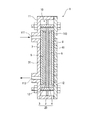
図2には燃料電池1の側断面図が示されている。燃料電池1は、直接メタノール形燃料電池(DMFC)であり、図2に示されるように、燃料電池セル10がケース11に収納されて構成されている。なお、本実施形態では、説明を簡略化するため、図2に示すように単一の燃料電池セル10で構成した燃料電池1を図示するが、もちろん燃料電池1が、この燃料電池セル10を複数枚積層したスタック構造とされていてもよい。
FIG. 2 shows a side sectional view of the fuel cell 1. The fuel cell 1 is a direct methanol fuel cell (DMFC). As shown in FIG. 2, the
燃料電池セル10は、電解質膜としての高分子固体電解質膜2と、この高分子固体電解質膜2の両面に一体的に形成されるアノード電極3およびカソード電極4と、アノード電極3側に配置される燃料拡散層5と、カソード電極4側に配置される空気拡散層6と、これら燃料拡散層5および空気拡散層6の外側にそれぞれ設けられるとともに、アノード電極3およびカソード電極4の間に発生した電気エネルギを取り出す集電体7,8とを備えている。この燃料電池セル10は、ケース11に収納され、ガスケット12によって高分子固体電解質膜2の両側から挟持されている。これにより、ケース11内部は、高分子固体電解質膜2を挟んでアノード電極3側とカソード電極4側とに封止されて分離されている。
すなわち、ケース11内壁とアノード電極3との間の領域は、液密に構成され、燃料が供給されるアノード側反応室としての燃料室31となっている。また、ケース11内壁とカソード電極4との間の領域は、空気が供給されるカソード側反応室としての空気室41となっている。なお、燃料としては、メタノール(CH3OH)水溶液が供給される。
The
That is, the region between the inner wall of the
ケース11のアノード電極3側には、燃料を燃料室31に供給するための燃料供給口111と、アノード電極3での反応が終了した燃料を外部に排出するための燃料排出口112とが形成されている。この燃料排出口112には、排出された溶液が流通する連通配管としての再循環配管108が接続されており、この再循環配管108が純水タンク102に接続されることにより、燃料室31と純水タンク102とが連通している。
ケース11のカソード電極4側には、空気を空気室41に供給するための複数の空気供給口113が形成されている。この空気供給口113は、大気に開放されることで、空気室41への空気の供給を自然吸気とする構造となっている。なお。空気室41への空気供給は、エアポンプなどによって空気室41に強制的に空気を供給する構造であってもよい。
On the
A plurality of
高分子固体電解質膜2の両面には、外縁から所定幅寸法を隔てた所定範囲内に略矩形状のアノード電極3およびカソード電極4が一体的に形成されている。高分子固体電解質膜2は、プロトン伝導性高分子で構成される高分子固体電解質樹脂が、延伸多孔質ポリテトラフルオロエチレン(Poly Tetra Fluoro Ethylene, PTFE)フィルムの多孔空隙部に含浸されることにより構成されている。高分子固体電解質樹脂としては、例えばナフィオン(デュポン社商標)等のパーフルオロスルホン酸系ポリマー、フッ素系ポリマー、炭化水素系ポリマーなどが採用できる。また場合によってはこの高分子固体電解質樹脂に、電子導電性の生じない範囲で白金などの触媒やカーボン粉末、各種セラミックス粉末などを加えてもよい。
A substantially
なお、延伸多孔質ポリテトラフルオロエチレン(PTFE)フィルムは、PTFEの塊を延伸多孔化して得られる、多数の微小結節とそれらの微小結節から延出して微小結節相互を三次元的に連結する微細繊維とからなる構造を有する多孔質PTFEフィルムであり、このフィルムには、厚み方向に貫通する多数の孔が形成される。本実施形態においてこの延伸多孔質PTFEフィルムの膜厚は、1〜100μm、好ましくは3〜30μmで、孔径は0.05〜5μm、好ましくは0.5〜2μmで、空隙率は60%〜98%、好ましくは80〜92%である。膜厚が薄すぎると短絡やガス漏れ(クロスリーク)が発生しやすくなり、厚すぎると電気抵抗が高くなる。また孔径が小さすぎると高分子固体電解質樹脂の含浸が困難となり、大きすぎると高分子固体電解質樹脂の保持力が弱くなり、また補強効果も弱くなる。そして、空隙率が小さすぎると高分子固体電解質膜としての抵抗が大きくなり、大きすぎると一般にPTFE自体の強度が弱くなり補強効果が得られない。 In addition, a stretched porous polytetrafluoroethylene (PTFE) film is obtained by stretching a porous PTFE mass to obtain a microscopic connection between a large number of micronodules and the micronodules three-dimensionally connected to each other. It is a porous PTFE film having a structure composed of fibers, and a large number of holes penetrating in the thickness direction are formed in this film. In the present embodiment, the stretched porous PTFE film has a thickness of 1 to 100 μm, preferably 3 to 30 μm, a pore diameter of 0.05 to 5 μm, preferably 0.5 to 2 μm, and a porosity of 60% to 98. %, Preferably 80 to 92%. If the film thickness is too thin, short circuits and gas leaks (cross leaks) are likely to occur, and if it is too thick, the electrical resistance increases. If the pore size is too small, impregnation of the polymer solid electrolyte resin becomes difficult, and if it is too large, the holding power of the polymer solid electrolyte resin becomes weak and the reinforcing effect becomes weak. If the porosity is too small, the resistance of the polymer solid electrolyte membrane is increased. If it is too large, the strength of PTFE itself is generally weakened and a reinforcing effect cannot be obtained.
アノード電極3およびカソード電極4は、メタノールの分解のための触媒を担持したカーボン触媒電極膜から構成される。ここで、触媒としては、例えば白金等が採用できる。なお、アノード電極3側では、メタノールと触媒との反応により発生する中間生成物である一酸化炭素COの被毒を防止するため、少なくともアノード電極3側の触媒には、白金およびルテニウムの合金等を採用することがより好ましい。
ここで、高分子固体電解質膜2、アノード電極3、およびカソード電極4は、一体的に形成されて膜電極接合体20が構成されている。
燃料拡散層5および空気拡散層6は、メッシュの金属フォーム(例えばスチールウール等)からなる多孔性膜であり、供給される燃料および酸素をそれぞれ拡散してアノード電極3およびカソード電極4に導く。なお、これら燃料拡散層5および空気拡散層6は、それぞれ、アルミニウム、ステンレス鋼等であってもよく、またスポンジチタン等の多孔性金属材料、カーボンペーパ紙にカーボンを担持したものやカーボンクロス等であってもよい。
また、集電体7,8には、それぞれ図示しないリード線が接続されており、外部の負荷に接続されている。
The
Here, the polymer
The
Further, lead wires (not shown) are connected to the
メタノールタンク101および純水タンク102は、燃料室31への流路が開閉可能なバルブ101A,102Aを備えている。これらのバルブ101A,102Aは、供給制御手段106に電気的に接続されており、供給制御手段106からの指令によりそれぞれ個別に開閉可能となっており、その開度も調整可能となっている。なお、メタノールタンク101および純水タンク102は、一体のケースの内部が仕切られて形成されている構成であることが好ましく、例えばいわゆるカートリッジ方式で、メタノールタンク101および純水タンク102が同時に簡単に交換可能な構造であることが望ましい。
図3には、メタノールタンク101および純水タンク102の概略図が示されている。この図3において、メタノールタンク101および純水タンク102は一体的に形成されており、それぞれメタノールポンプ103および純水ポンプ104に連通する配管が接続されている。また、純水タンク102には、燃料室31に連通する再循環配管108が接続されている。この再循環配管108により、燃料室31で反応が終了した溶液が純水タンク102に収納される。また、前述の図1に示されるように、純水タンク102には、純水タンク102内の水に含まれるメタノール濃度を検出する燃料濃度検出手段としてのメタノールセンサ107が設けられている。再循環配管108によって燃料室31からの溶液を純水タンク102に戻すと、溶液内に含まれる微量のメタノールが長期間の使用により蓄積し、純水タンク102内の水がある程度のメタノールを含むメタノール水溶液となる場合がある。そこで、このメタノールセンサ107は、純水タンク102内のメタノール濃度を検出し、メタノール濃度検出信号(燃料濃度検出信号)を供給制御手段106に出力する。
The
FIG. 3 shows a schematic diagram of the
純水タンク102は、メタノールタンク101内のメタノール量に対して、燃料電池1での反応に必要な量の水が収納できるだけの容量で形成されている。この純水タンク102には、純水タンク102から溢れた水を吸収保持する保持手段としての吸収パッド9が設けられている。
吸収パッド9は、蒸散体としての蒸散層91と、吸収体としての吸収層92とが積層されて一体的に構成されている。蒸散層91は、純水タンク102に隣接して、つまり純水タンク102の一側面に当接して配置されており、水分保持能力を有する任意の材料で構成される。この蒸散層91には、純水タンク102に連通する配管93が設けられており、純水タンク102から溢れた余剰分の水がこの配管93を通って蒸散層91に流れると、蒸散層91はこの水を一時的に内部に保持するとともに、一定量ずつ表面から大気に蒸散させる。したがって、この蒸散層91は大気に対向して配置されていることが望ましく、例えば燃料電池システム100全体をケースに収納する場合などでは、ケースに複数の通気口などを設け、蒸散層91を通気口に対向して配置すればよい。また、蒸散層91は、蒸散効率を高めるため、表面積が大きくなるように構成されることが望ましく、例えば蒸散層91が当接される純水タンク102側面よりも大きい面積の板状(シート状)に形成すれば、当該純水タンク102周囲に蒸散層91が突出して蒸散面積が大きくなる。
The
The absorbent pad 9 is integrally configured by laminating a
吸収層92は、例えば高分子吸収体などで構成されるゲル状吸収体で、蒸散層91で吸収蒸散しきれない水分を吸収し、内部に保持する。吸収層92の寸法は、蒸散層91と同じ面積の板状(シート状)に形成されることが望ましく、燃料室31から回収される溶液の量や、蒸散層91で蒸散できる水分量などを勘案して適宜設定されることが望ましい。
The
メタノールポンプ103および純水ポンプ104は、ミキサ105に接続されており、それぞれ所定量のメタノールおよび純水をメタノールタンク101および純水タンク102からミキサ105に送液する。これらのポンプ103,104は、供給制御手段106に電気的に接続されており、供給制御手段106からの送液指令信号によりポンプ103,104のON,OFFが制御される。
ミキサ105は、燃料供給口111に接続されており、供給制御手段106からの混合指令信号に基づいて、メタノールタンク101からのメタノールと、純水タンク102からの純水を混合し、メタノールが純水中に均一に分散されたメタノール水溶液を作成する混合手段となっている。なお、メタノールのみ、または純水のみを燃料室31に供給する場合には、ミキサ105は一種類の液体を混合するのみで、実質的にはその機能を発揮することなく液体が通過するのみとなる。
ここで、本実施形態ではメタノールタンク101、バルブ101A、およびメタノールポンプ103を備えてメタノール供給手段が構成されており、また純水タンク102、バルブ102A、および純水ポンプ104を備えて水供給手段が構成されている。
The
The
Here, in this embodiment, a methanol supply means is configured by including the
供給制御手段106は、燃料室31内のメタノール水溶液の濃度を予め設定された所定範囲内に維持するように、メタノールおよび水の供給量を制御する。つまり、供給制御手段106は、バルブ101A,102Aの開度を調整することにより、所定濃度のメタノール水溶液を供給するとともに、メタノールセンサ107からのメタノール濃度検出信号に基づいて、バルブ101A,102Aの開度を制御し、燃料室31に供給されるメタノール水溶液の濃度を所定濃度範囲内に制御する。
具体的には、供給制御手段106は、メタノールセンサ107からのメタノール濃度検出信号に基づいてバルブ101Aの開度を演算する演算手段(図示せず)を備える。演算手段には、例えばメタノール濃度検出信号に基づいて、純水タンク102内の水を所定濃度のメタノール水溶液とするのに必要なメタノールの追加量を算出し、バルブ101Aの開度を算出する演算式が記憶されている。供給制御手段106は、この演算手段の演算結果に基づいてバルブ101Aを開度を制御する。
ここで、燃料室31内におけるメタノール水溶液の濃度の所定範囲は、燃料室31内でのメタノールと触媒との反応効率が良好となり、かつ高分子固体電解質膜2のクロスオーバーが良好に防止される範囲で設定されることが好ましく、燃料電池1の容量、高分子固体電解質膜2の材質、性能などを勘案して適宜設定され、例えば3%〜5%または1mol/l〜8mol/lの範囲内で設定される。
The supply control means 106 controls the supply amounts of methanol and water so as to maintain the concentration of the aqueous methanol solution in the
Specifically, the
Here, the predetermined range of the concentration of the aqueous methanol solution in the
次に、このような燃料電池システム100の動作について説明する。
まず、燃料電池システム100の起動時には、供給制御手段106から出力される初期メタノール水溶液供給指令により、燃料室31にメタノール水溶液を充満させる。この指令信号により、バルブ101A,102Aが開き、メタノールおよび純水がそれぞれ送液される。このとき、バルブ101A,102Aの開度は、メタノール水溶液の濃度が所定範囲内となるように、あらかじめ設定されている。メタノールおよび純水は、メタノールポンプ103および純水ポンプ104によってミキサ105に送られ、ミキサ105で均一に混合された後、燃料室31に供給される。
Next, the operation of the
First, when the
燃料室31では、メタノール水溶液がアノード電極3の触媒によって下記の式(1)の酸化反応を生じ、この反応により二酸化炭素CO2とプロトンH+と電子e−とを生成する。
CH3OH+H2O→CO2+6H++6e− …(1)
プロトンH+は、高分子固体電解質膜2を透過してカソード電極4側に移動することにより、集電体7,8の両端に電圧が生じる。プロトンH+がカソード電極4側に到達すると、このプロトンH+と、外部負荷を通って仕事をした後にカソード電極4に到達した電子e−とがカソード電極4の触媒によって空気室41内の空気中の酸素O2と反応して式(2)の還元反応が生じる。
3/2O2+6H++6e−→3H2O …(2)
アノード電極3側で反応が終了した溶液は、再循環配管108を通って純水タンク102に収納される。この溶液は、純水タンク102内の純水と混合し、再び純水ポンプ104によって送液されて、メタノールを所定濃度のメタノール水溶液に希釈するのに使用される。また、カソード電極4側で生成された水は、水蒸気の状態で空気供給口113を通って大気に開放される。
In the
CH 3 OH + H 2 O → CO 2 + 6H + + 6e − (1)
Proton H + passes through the polymer
3 / 2O 2 + 6H + + 6e − → 3H 2 O (2)
The solution that has been reacted on the
再循環配管108を通って純水タンク102に収納される溶液には、燃料室31で未反応であったメタノールが少量含まれている場合がある。この場合には、燃料電池システム100を長時間使用すると、純水タンク102内にメタノールが蓄積され、純水タンク102内の水が濃度の薄いメタノール水溶液となる。
そこで、供給制御手段106は、メタノールセンサ107からのメタノール濃度検出信号を監視し、演算手段がメタノール濃度検出信号に基づいてバルブ101Aの開度を演算する。供給制御手段106は、この演算結果に基づいて随時バルブ101Aの開度を調整、制御する。
The solution stored in the
Therefore, the
燃料室31から再循環配管108を通って純水タンク102に回収される溶液には、未反応のメタノールやその他、メタノールと水との反応により生成される、例えば二酸化炭素、蟻酸、ホルムアルデヒド、一酸化炭素等の副生成物が含まれているため、燃料電池システム100を使用するにしたがい、純水タンク102内の水が増加して過剰となる場合がある。この余剰分の水は、純水タンク102から溢れると、配管93を通って吸収パッド9の蒸散層91に供給される。配管93からの水は、蒸散層91全面に拡散され、蒸散層91に一時的に保持されるとともに、蒸散層91表面から一定量ずつ大気に蒸散される。
また、蒸散層91で保持、蒸散しきれないさらなる余剰分の水は、蒸散層91から吸収層92に移動し、吸収層92に吸収、保持される。
メタノールタンク101内のメタノールがなくなった場合には、メタノールタンク101および純水タンク102にそれぞれメタノールおよび純水を追加するか、またはメタノールタンク101および純水タンク102ごと交換すればよい。
また、吸収パッド9は所定量以上の水を吸収した場合に交換すればよく、吸収パッド9がメタノールタンク101および純水タンク102と一体に設けられている場合には、メタノールタンク101および純水タンク102を交換する際に吸収パッド9もともに交換すればよい。この際、吸収パッド9の吸収能力および蒸散能力は、メタノールタンク101内のメタノール量に応じて、メタノールタンク101内のメタノールが燃料電池1で反応したときに発生する水の量を勘案して設定されることが望ましい。
The solution recovered from the
Further, a further excessive amount of water that cannot be held and evaporated in the
When the methanol in the
The absorption pad 9 may be replaced when a predetermined amount or more of water is absorbed. When the absorption pad 9 is provided integrally with the
このような本実施形態によれば、次のような効果が得られる。
(1) 再循環配管108により燃料室31と純水タンク102とを連通したので、燃料室31で反応が終了した溶液を純水タンク102に収納することができる。したがって、燃料室31に供給した水を、メタノールの希釈用に再利用できるので、純水タンク102にあらかじめ収納する水を少なくでき、純水タンク102の小型化を促進できる。よって、燃料電池システム100の小型化、軽量化を促進できる。
According to this embodiment, the following effects can be obtained.
(1) Since the
(2) 供給制御手段106が、メタノールセンサ107からのメタノール濃度検出信号に基づいてバルブ101Aの開度を制御してメタノールの供給量を調整するので、燃料室31内のメタノール水溶液の濃度を所定範囲内に制御できる。したがって、燃料室31での反応効率を安定させることができ、燃料電池1から安定した発電量が得られる。
(2) Since the supply control means 106 controls the opening amount of the
(3) 純水タンク102から溢れた余剰分の水を吸収パッド9で吸収するので、純水タンク102には、燃料電池1で使用する必要分の水のみを収納でき、純水タンク102の容量を最小限に抑制できる。これにより、純水タンク102の小型化を促進できるとともに、燃料電池システム100の小型化を促進できる。
(3) Since the excess water overflowing from the
(4) 吸収パッド9が、蒸散層91を備えているので、純水タンク102から溢れた余剰分の水の一部を大気に蒸散できる。したがって、燃料室31から回収された溶液の全量を燃料電池システム100内で保持する必要がなく、燃料電池システム100の軽量化を促進できる。この場合において、蒸散層91が水を一時的に保持し、その一部の一定量を蒸散させるので、蒸散量を調整でき、燃料電池システム100外部を濡らすなどの不具合を良好に回避できる。
また、吸収パッド9がゲル状吸収体で構成される吸収層92を備えているので、蒸散層91で保持、蒸散しきれない水分を吸収層92で吸収、保持することができる。したがって、吸収パッド9での水分の吸収をより確実にできるとともに、蒸散層91の蒸散量を過剰にすることなく適量に保持できる。
(4) Since the absorption pad 9 includes the
Moreover, since the absorption pad 9 is provided with the
なお、本発明は前述の実施形態に限定されるものではなく、本発明の目的を達成できる範囲での変形、改良等は本発明に含まれるものである。
供給制御手段は、メタノール濃度検出信号に基づいてバルブ101Aの開度を演算する演算手段を備えているものに限らず、例えば燃料濃度検出信号に対する適切な燃料供給量(前述の実施形態ではバルブ101Aの開度)をテーブルやマップとして記憶する記憶手段を備えていてもよい。この場合には、供給制御手段は、記憶手段に記憶されたテーブル等で、検出された燃料濃度検出信号に対応する燃料供給量(バルブの開度)を読み込み、燃料供給量を制御すればよい。この場合には、記憶手段に予め燃料濃度検出信号に対する燃料供給量が記憶されているので、供給制御手段で演算等する必要がなく、制御が簡略化するとともに、燃料電池システム100の省力化を促進できる。
また、燃料濃度検出手段による濃度検出は、連続的に行うものに限らず、例えば所定時間毎に検出してもよい。このように構成すれば、燃料濃度検出のために必要な電力を節約できるので、省力化を促進できる。
燃料濃度検出手段は、必ずしも設けられていなくてもよく、例えばアノード側反応室に供給される燃料のほとんど全てが反応に供される場合などでは、アノード側反応室から排出される溶液には燃料がほとんど含まれないので、水収納手段に燃料が過剰に蓄積されることがない。
It should be noted that the present invention is not limited to the above-described embodiments, and modifications, improvements, and the like within the scope that can achieve the object of the present invention are included in the present invention.
The supply control means is not limited to one provided with a calculation means for calculating the opening degree of the
Further, the concentration detection by the fuel concentration detection means is not limited to being performed continuously, but may be detected, for example, every predetermined time. With this configuration, it is possible to save electric power necessary for detecting the fuel concentration, so that labor saving can be promoted.
The fuel concentration detection means is not necessarily provided. For example, when almost all of the fuel supplied to the anode side reaction chamber is used for the reaction, the solution discharged from the anode side reaction chamber contains no fuel. Is hardly contained, so that the fuel is not excessively accumulated in the water storage means.
保持手段が、蒸散体および吸収体を積層して構成されている場合において、蒸散体は水収納手段に隣接、当接されているものに限らず、例えば吸収体が水収納手段に隣接、当接されていてもよい。この場合には、水収納手段から吸収体を挟んで反対側の蒸散体に連通する配管を設けて、水収納手段から溢れた水を蒸散体に供給するように構成すればよい。この場合でも、蒸散体を大気側に対向配置すると、蒸散体からの水分の蒸散を促進できる。また、蒸散体が水収納手段と吸収体との間に挟まれないので、大気への対向面積が大きくなるため、蒸散効率が良好となる。
保持手段は、必ずしも蒸散体が設けられていなくてもよく、例えば、保持手段として吸収体のみが設けられ、水収納手段から溢れた水の全量を吸収体で吸収、保持する構成であってもよい。
保持手段は、必ずしも必要ではなく、例えば水収納手段の収納能力を、アノード側反応室から回収される溶液の量を勘案して設定すれば、連通配管を通って溶液の全量が水収納手段に収納されて溢れることがないので、保持手段を設ける必要がない。
When the holding means is configured by laminating a transpiration body and an absorber, the transpiration body is not limited to the one adjacent to or in contact with the water storage means. For example, the absorption body is adjacent to the water storage means, It may be touched. In this case, a pipe that communicates from the water storage means to the opposite transpiration body with the absorber interposed therebetween may be provided so that water overflowing from the water storage means is supplied to the transpiration body. Even in this case, if the transpiration body is disposed opposite to the atmosphere side, the transpiration of moisture from the transpiration body can be promoted. Further, since the transpiration body is not sandwiched between the water storage means and the absorber, the facing area to the atmosphere is increased, and the transpiration efficiency is improved.
The holding means may not necessarily be provided with a transpiration body. For example, the holding means may be provided with only an absorber, and the absorber may absorb and hold the entire amount of water overflowing from the water storage means. Good.
The holding means is not necessarily required. For example, if the storage capacity of the water storage means is set in consideration of the amount of the solution recovered from the anode side reaction chamber, the entire amount of the solution passes through the communication pipe to the water storage means. Since it is stored and does not overflow, it is not necessary to provide holding means.
保持手段が蒸散体を備えている場合には、蒸散体を加熱する加熱手段を設けて、蒸散体からの水の蒸散を促進するように構成してもよい。この場合に加熱手段としては、例えば蒸散体近傍に設けられる発熱体を用いてもよいし、燃料電池の反応効率を良好に保持できる範囲内で、燃料電池における発熱量を利用してもよい。また、蒸散体の蒸散を促す蒸散促進手段としては、加熱手段を設けるものの他、例えば送風手段を設けてもよい。 When the holding means includes a transpiration body, a heating means for heating the transpiration body may be provided to promote the transpiration of water from the transpiration body. In this case, as the heating means, for example, a heating element provided in the vicinity of the vaporizer may be used, or the amount of heat generated in the fuel cell may be used within a range in which the reaction efficiency of the fuel cell can be satisfactorily maintained. Moreover, as a transpiration | evaporation acceleration | stimulation means which promotes transpiration | evaporation of a transpiration | evaporation body, you may provide a ventilation means other than what provides a heating means, for example.
燃料がメタノールである場合には、アノード側反応室外側に、メタノールと水との反応後に生成される二酸化炭素を分離する気液分離膜が設けられていてもよい。この場合には、アノード側反応室での反応によって生成された二酸化炭素が気液分離膜によって分離されて外部に排出されるので、連通配管には二酸化炭素が除去された溶液が流通する。したがって、水収納手段に収納される溶液に気体が混在せず、より純度の高い水を戻すことができるとともに、気体が混入した燃料水溶液がアノード側反応室に供給されるのを良好に防止できる。
また、気液分離膜によってアノード側反応室内の二酸化炭素が除去されるので、燃料が良好にアノード側反応室内の触媒に接触するから、燃料電池の反応効率を向上させることができる。
When the fuel is methanol, a gas-liquid separation membrane for separating carbon dioxide generated after the reaction between methanol and water may be provided outside the anode side reaction chamber. In this case, carbon dioxide produced by the reaction in the anode side reaction chamber is separated by the gas-liquid separation membrane and discharged to the outside, so that the solution from which carbon dioxide has been removed flows through the communication pipe. Therefore, gas is not mixed in the solution stored in the water storage means, water with higher purity can be returned, and the aqueous fuel solution mixed with gas can be well prevented from being supplied to the anode reaction chamber. .
In addition, since the carbon dioxide in the anode side reaction chamber is removed by the gas-liquid separation membrane, the fuel comes into good contact with the catalyst in the anode side reaction chamber, so that the reaction efficiency of the fuel cell can be improved.
連通配管で水収納手段に収納された水は、燃料電池の燃料を希釈して水溶液を作成する用途の他、例えばカソード側反応室に空気とともに少量の水を送って電解質膜を適度な湿度に保持するために用いてもよい。
または、連通配管で水収納手段に収納された水は、燃料電池に供給される燃料の水溶液を作成する用途の他、例えば燃料電池システムが改質器を有する場合では、改質器に供給される燃料の水溶液を作成する用途に用いてもよい。
燃料は、メタノールに限らず、任意の材料が採用できる。また、燃料電池システムが改質器を含む場合では、燃料はメタノールなどのアルコール系燃料の他、例えばデカリンなどの有機ハイドライド燃料や、水素化ホウ素ナトリウムなどのボロハイドライド燃料などの任意の材料が採用されている。
本発明の燃料電池システムは、軽量化、小型化を促進できるので、例えば携帯電話やノートパソコンなどの携帯機器、車、その他任意の機器に適用できる。
The water stored in the water storage means by the communication pipe is used for diluting the fuel of the fuel cell to create an aqueous solution, for example, sending a small amount of water together with air to the cathode reaction chamber to bring the electrolyte membrane to an appropriate humidity. It may be used to hold.
Alternatively, the water stored in the water storage means by the communication pipe is supplied to the reformer, for example, in the case where the fuel cell system has a reformer in addition to the use of preparing an aqueous solution of the fuel supplied to the fuel cell. You may use for the use which produces the aqueous solution of the fuel which is.
The fuel is not limited to methanol, and any material can be adopted. In addition, when the fuel cell system includes a reformer, any material such as an organic fuel such as decalin or a borohydride fuel such as sodium borohydride is used as the fuel in addition to an alcohol fuel such as methanol. Has been.
Since the fuel cell system of the present invention can promote weight reduction and downsizing, it can be applied to portable devices such as mobile phones and notebook computers, cars, and other arbitrary devices.
本発明を実施するための最良の構成、方法などは、以上の記載で開示されているが、本発明は、これに限定されるものではない。すなわち、本発明は、主に特定の実施形態に関して特に図示され、かつ、説明されているが、本発明の技術的思想および目的の範囲から逸脱することなく、以上述べた実施形態に対し、形状、材質、数量、その他の詳細な構成において、当業者が様々な変形を加えることができるものである。
したがって、上記に開示した形状、材質などを限定した記載は、本発明の理解を容易にするために例示的に記載したものであり、本発明を限定するものではないから、それらの形状、材質などの限定の一部もしくは全部の限定を外した部材の名称での記載は、本発明に含まれるものである。
The best configuration, method and the like for carrying out the present invention have been disclosed in the above description, but the present invention is not limited to this. That is, the invention has been illustrated and described primarily with respect to particular embodiments, but may be configured for the above-described embodiments without departing from the scope and spirit of the invention. Various modifications can be made by those skilled in the art in terms of materials, quantity, and other detailed configurations.
Therefore, the description limited to the shape, material, etc. disclosed above is an example for easy understanding of the present invention, and does not limit the present invention. The description by the name of the member which remove | excluded the limitation of one part or all of such restrictions is included in this invention.
1…燃料電池、2…高分子固体電解質膜(電解質膜)、3…アノード電極、4…カソード電極、9…吸収パッド(保持手段)、31…燃料室(アノード側反応室)、41…空気室(カソード側反応室)、91…蒸散層(蒸散体)、92…吸収層(吸収体)、100…燃料電池システム、101…メタノールタンク(燃料収納手段)、102…純水タンク(水収納手段)、106…供給制御手段、107…メタノールセンサ(燃料濃度検出手段)、108…再循環配管(連通配管)。 DESCRIPTION OF SYMBOLS 1 ... Fuel cell, 2 ... Polymer solid electrolyte membrane (electrolyte membrane), 3 ... Anode electrode, 4 ... Cathode electrode, 9 ... Absorption pad (holding means), 31 ... Fuel chamber (anode side reaction chamber), 41 ... Air Chamber (cathode side reaction chamber), 91 ... transpiration layer (vaporizer), 92 ... absorption layer (absorber), 100 ... fuel cell system, 101 ... methanol tank (fuel storage means), 102 ... pure water tank (water storage) Means), 106 ... Supply control means, 107 ... Methanol sensor (fuel concentration detection means), 108 ... Recirculation piping (communication piping).
Claims (5)
当該燃料電池に供給される燃料を収納する燃料収納手段と、
当該燃料電池に供給され、前記アノード側反応室内の燃料濃度を所定範囲内に希釈することに使用する水を収納する水収納手段と、
前記アノード側反応室と前記水収納手段とを連通し、前記アノード側反応室で反応が終了した溶液を前記水収納手段に流通させる連通配管と、
前記水収納手段から溢れた水を保持する保持手段と、
前記水収納手段内の燃料濃度を検出する燃料濃度検出手段と、
前記燃料濃度検出手段からの燃料濃度検出信号に応じて、前記アノード側反応室内の燃料濃度が前記所定範囲内となるように前記燃料および前記水の供給量を制御する供給制御手段と、
を備えることを特徴とする燃料電池システム。 A fuel cell having an electrolyte membrane, an anode side reaction chamber, and a cathode side reaction chamber, supplying fuel to the anode side reaction chamber to obtain electric energy;
Fuel storage means for storing fuel supplied to the fuel cell ;
Water storage means for storing water supplied to the fuel cell and used for diluting the fuel concentration in the anode reaction chamber within a predetermined range ;
A communication pipe that communicates the anode-side reaction chamber and the water storage means, and distributes the solution that has been reacted in the anode-side reaction chamber to the water storage means;
Holding means for holding water overflowing from the water storage means;
Fuel concentration detection means for detecting the fuel concentration in the water storage means;
And in response to said fuel concentration detection signal from the fuel concentration detection means, supply control means for the fuel concentration in the anode reaction chamber to control the supply amount of the fuel and the water to be within a predetermined range,
Fuel cell system comprising: a.
Priority Applications (1)
| Application Number | Priority Date | Filing Date | Title |
|---|---|---|---|
| JP2004116791A JP4843906B2 (en) | 2004-04-12 | 2004-04-12 | Fuel cell system and equipment |
Applications Claiming Priority (1)
| Application Number | Priority Date | Filing Date | Title |
|---|---|---|---|
| JP2004116791A JP4843906B2 (en) | 2004-04-12 | 2004-04-12 | Fuel cell system and equipment |
Publications (3)
| Publication Number | Publication Date |
|---|---|
| JP2005302519A JP2005302519A (en) | 2005-10-27 |
| JP2005302519A5 JP2005302519A5 (en) | 2007-06-07 |
| JP4843906B2 true JP4843906B2 (en) | 2011-12-21 |
Family
ID=35333755
Family Applications (1)
| Application Number | Title | Priority Date | Filing Date |
|---|---|---|---|
| JP2004116791A Expired - Fee Related JP4843906B2 (en) | 2004-04-12 | 2004-04-12 | Fuel cell system and equipment |
Country Status (1)
| Country | Link |
|---|---|
| JP (1) | JP4843906B2 (en) |
Family Cites Families (20)
| Publication number | Priority date | Publication date | Assignee | Title |
|---|---|---|---|---|
| JPH05283094A (en) * | 1992-03-31 | 1993-10-29 | Toshiba Corp | Fuel cell |
| JPH06188008A (en) * | 1992-04-01 | 1994-07-08 | Toshiba Corp | Fuel cell |
| JP3447875B2 (en) * | 1995-12-06 | 2003-09-16 | 本田技研工業株式会社 | Direct methanol fuel cell |
| JP3623409B2 (en) * | 1999-09-30 | 2005-02-23 | 株式会社東芝 | Fuel cell |
| JP4961626B2 (en) * | 2000-05-24 | 2012-06-27 | ソニー株式会社 | Mounting method of electric energy generator and computer incorporating electric energy generator |
| JP3893898B2 (en) * | 2001-04-20 | 2007-03-14 | 株式会社ジーエス・ユアサコーポレーション | FUEL CELL SYSTEM, FUEL CELL SYSTEM OPERATION CONTROL METHOD, AND PROGRAM FOR CONTROLLING FUEL CELL SYSTEM OPERATION |
| JP4131916B2 (en) * | 2001-05-02 | 2008-08-13 | 株式会社東芝 | Operation method of fuel cell power generator |
| US20030003341A1 (en) * | 2001-06-29 | 2003-01-02 | Kinkelaar Mark R. | Liquid fuel cell reservoir for water and/or fuel management |
| JP4599772B2 (en) * | 2001-07-19 | 2010-12-15 | カシオ計算機株式会社 | Power system |
| US6924054B2 (en) * | 2001-10-29 | 2005-08-02 | Hewlett-Packard Development Company L.P. | Fuel supply for a fuel cell |
| JP3925695B2 (en) * | 2001-10-30 | 2007-06-06 | 株式会社ジーエス・ユアサコーポレーション | Liquid fuel direct supply fuel cell |
| JP4202109B2 (en) * | 2001-12-28 | 2008-12-24 | パナソニック株式会社 | Fuel cell system |
| JP2003203668A (en) * | 2002-01-08 | 2003-07-18 | Sony Corp | Product water recovery device, product water recovery method, power generator, product water discharge device, product water discharge method, and product water recovery system |
| US6981877B2 (en) * | 2002-02-19 | 2006-01-03 | Mti Microfuel Cells Inc. | Simplified direct oxidation fuel cell system |
| JP3748417B2 (en) * | 2002-03-29 | 2006-02-22 | 株式会社東芝 | Direct liquid fuel fuel cell power generator and control method thereof |
| JP4234944B2 (en) * | 2002-04-23 | 2009-03-04 | 秀治 田中 | Fuel cell |
| JP2003331900A (en) * | 2002-05-14 | 2003-11-21 | Hitachi Ltd | Fuel cell |
| JP2003331885A (en) * | 2002-05-17 | 2003-11-21 | Daihatsu Motor Co Ltd | Fuel cell device |
| JP4278349B2 (en) * | 2002-06-28 | 2009-06-10 | 三洋電機株式会社 | Fuel cell |
| JP3878092B2 (en) * | 2002-08-30 | 2007-02-07 | ヤマハ発動機株式会社 | Direct reforming fuel cell system |
-
2004
- 2004-04-12 JP JP2004116791A patent/JP4843906B2/en not_active Expired - Fee Related
Also Published As
| Publication number | Publication date |
|---|---|
| JP2005302519A (en) | 2005-10-27 |
Similar Documents
| Publication | Publication Date | Title |
|---|---|---|
| JP5519858B2 (en) | Direct oxidation fuel cell system | |
| US20100099005A1 (en) | Vapor fed direct hydrocarbon alkaline fuel cells | |
| CN101295796B (en) | Fuel cell system | |
| JP2005235519A (en) | Fuel cell, fuel cell system, and apparatus | |
| JP2006318712A (en) | Fuel cell | |
| US8968946B2 (en) | Fuel cell systems | |
| JP2006024401A (en) | Fuel cell | |
| JP2005317436A (en) | Fuel cell system and equipment | |
| JP2008310995A (en) | Fuel cell | |
| JP4843906B2 (en) | Fuel cell system and equipment | |
| JP5127267B2 (en) | Fuel cell and fuel cell system | |
| JPWO2008068887A1 (en) | Fuel cell | |
| JPWO2008068886A1 (en) | Fuel cell | |
| JP2005302518A (en) | Fuel cell system and equipment | |
| JP4945914B2 (en) | Fuel cell | |
| US20090263688A1 (en) | Fuel cell | |
| JP2005310589A (en) | Fuel cell system and equipment | |
| JP2008218030A (en) | Fuel cell | |
| JP2011096468A (en) | Fuel cell | |
| JP2011096466A (en) | Fuel cell | |
| JP2011070852A (en) | Fuel cell | |
| TW200810195A (en) | Fuel cell container, container for electronic device having fuel cell mounted thereon and fuel cell provided with container | |
| JP2009123619A (en) | Fuel cell | |
| JP2008218049A (en) | Fuel cell and fuel cell | |
| JP2009043720A (en) | Fuel cell |
Legal Events
| Date | Code | Title | Description |
|---|---|---|---|
| RD04 | Notification of resignation of power of attorney |
Free format text: JAPANESE INTERMEDIATE CODE: A7424 Effective date: 20070403 |
|
| A521 | Written amendment |
Free format text: JAPANESE INTERMEDIATE CODE: A523 Effective date: 20070412 |
|
| A621 | Written request for application examination |
Free format text: JAPANESE INTERMEDIATE CODE: A621 Effective date: 20070412 |
|
| A977 | Report on retrieval |
Free format text: JAPANESE INTERMEDIATE CODE: A971007 Effective date: 20101119 |
|
| A131 | Notification of reasons for refusal |
Free format text: JAPANESE INTERMEDIATE CODE: A131 Effective date: 20101130 |
|
| A521 | Written amendment |
Free format text: JAPANESE INTERMEDIATE CODE: A523 Effective date: 20110125 |
|
| TRDD | Decision of grant or rejection written | ||
| A01 | Written decision to grant a patent or to grant a registration (utility model) |
Free format text: JAPANESE INTERMEDIATE CODE: A01 Effective date: 20110913 |
|
| A01 | Written decision to grant a patent or to grant a registration (utility model) |
Free format text: JAPANESE INTERMEDIATE CODE: A01 |
|
| A61 | First payment of annual fees (during grant procedure) |
Free format text: JAPANESE INTERMEDIATE CODE: A61 Effective date: 20110926 |
|
| FPAY | Renewal fee payment (event date is renewal date of database) |
Free format text: PAYMENT UNTIL: 20141021 Year of fee payment: 3 |
|
| R150 | Certificate of patent or registration of utility model |
Free format text: JAPANESE INTERMEDIATE CODE: R150 |
|
| LAPS | Cancellation because of no payment of annual fees |